Documentation of Object-Oriented Systems and Frameworks
Documentation of Object-Oriented Systems and Frameworks
Documentation of Object-Oriented Systems and Frameworks

Create successful ePaper yourself
Turn your PDF publications into a flip-book with our unique Google optimized e-Paper software.
<strong>Documentation</strong> <strong>of</strong> <strong>Object</strong>-<strong>Oriented</strong><br />
<strong>Systems</strong> <strong>and</strong> <strong>Frameworks</strong><br />
COT/2-42-V2.4<br />
C<br />
*<br />
O<br />
T<br />
Centre for <strong>Object</strong> Technology
Centre for<br />
<strong>Object</strong> Technology<br />
Revision history: V0.1 990905 First draft outline<br />
V1.1 991208 Minor changes in Chapter 2<br />
V1.2 991212 Changes after doc meeting 10.12.<br />
V1.3 991213 Changes in Chapter 10<br />
V1.4 991213 Rewrite <strong>of</strong> 6.2.3, removed 6.2.4,6.2.5<br />
V1.5 991213 Changes to tools chapter<br />
V1.6 991214 Minor updates<br />
V1.7 000330 Minor updates after internal review<br />
V1.8 000413 Language review <strong>and</strong> correction<br />
V2.0 000810 Rewrite based on review feedback<br />
V2.1 000816 Rewrite based on 0008015 meeting<br />
V2.2 001011 Rewrite based on FOH comments<br />
V2.3 001220 Rewrite based on review feedback<br />
V2.4 010110 Reformat for publication<br />
Authors:<br />
Aarhus University:<br />
Kasper Østerbye, Ole Lehrmann Madsen, Elmer S<strong>and</strong>vad<br />
Bang & Olufsen:<br />
Carsten Bjerring<br />
Danfoss Instruments:<br />
Ole Kammeyer<br />
Danfoss Drives:<br />
Stefan Helleman Skov<br />
Danish Technological Institute:<br />
Finn Overgaard Hansen, Flemming Hansen<br />
Status:<br />
Publication:<br />
Final<br />
Public publication<br />
Summary:<br />
This report discusses documentation <strong>of</strong> the design <strong>and</strong> the implementation<br />
aspect <strong>of</strong> object-oriented systems <strong>and</strong> frameworks. The targets<br />
for the produced documentation <strong>and</strong> for this report are developers <strong>of</strong><br />
object-oriented s<strong>of</strong>tware. The report divides documentation into three<br />
main categories, tutorial, rationale, <strong>and</strong> reference documentation.<br />
Each kind <strong>of</strong> documentation is discussed <strong>and</strong> recommendations are<br />
presented. Tool support for the development <strong>and</strong> maintenance <strong>of</strong><br />
documentation are addressed as well.<br />
© Copyright 2000<br />
The Centre for <strong>Object</strong> Technology (COT) is a 3-<br />
year project concerned with research, application<br />
<strong>and</strong> implementation <strong>of</strong> object technology in<br />
Danish companies. The project is financially<br />
supported by The Danish National Centre for IT-<br />
Research (CIT) <strong>and</strong> the Danish Ministry <strong>of</strong> Industry.<br />
The participants are:<br />
Maersk Line, Maersk Training Center, Bang &<br />
Olufsen, WM-data, Rambøll, Danfoss, Systematic<br />
S<strong>of</strong>tware Engineering, Odense Steel Shipyard, A.P.<br />
Møller, Aarhus University, Odense University,<br />
University <strong>of</strong> Copenhagen, Danish Technological<br />
Institute <strong>and</strong> Danish Maritime Institute.
Centre for<br />
<strong>Object</strong> Technology<br />
1. INTRODUCTION............................................................................................................................................... 3<br />
1.1 PURPOSE AND SCOPE ........................................................................................................................................3<br />
1.2 TARGET GROUP .................................................................................................................................................3<br />
1.3 O-O SOFTWARE ELEMENTS.............................................................................................................................3<br />
1.4 HOW IS DOCUMENTATION OF OO SYSTEMS DIFFERENT ............................................................................5<br />
1.5 READING GUIDE ................................................................................................................................................5<br />
2. GENERAL NOTES ON DOCUMENTATION .......................................................................................... 6<br />
2.1 REQUIREMENTS FOR DOCUMENTATION.........................................................................................................6<br />
2.2 GUIDELINES FOR ARCHITECTURE DOCUMENTATION ..................................................................................7<br />
2.3 TRACEABILITY...................................................................................................................................................7<br />
3. TYPES OF DOCUMENTATION................................................................................................................... 8<br />
4. TUTORIAL DOCUMENTATION..............................................................................................................10<br />
5. RATIONALE DOCUMENTATION ...........................................................................................................11<br />
6. REFERENCE DOCUMENTATION...........................................................................................................12<br />
6.1 ENTITY-BASED REFERENCE DOCUMENTATION ..........................................................................................12<br />
6.2 ARCHITECTURE DOCUMENTATION ...............................................................................................................14<br />
6.2.1 Documenting Configurations............................................................................................................15<br />
6.2.2 Structuring the Architecture <strong>Documentation</strong>.................................................................................16<br />
6.2.3 Hierarchical Design Descriptions...................................................................................................18<br />
7. DOCUMENTATION IN THE DEVELOPMENT PROCESS.............................................................20<br />
7.1 WATERFALL DEVELOPMENT .........................................................................................................................20<br />
7.2 ITERATIVE DEVELOPMENT ............................................................................................................................20<br />
7.2.1 <strong>Documentation</strong> Process .....................................................................................................................20<br />
7.2.2 “2+1” View Model – as Process Driver.........................................................................................21<br />
8. TOOL SUPPORT FOR DOCUMENTATION.........................................................................................22<br />
8.1 AUTOMATIC GENERATION OF THE ENTITY-BASED REFERENCE DOCUMENTATION..............................24<br />
8.2 USE OF DEVELOPMENT ARTEFACTS IN DOCUMENTATION .......................................................................25<br />
8.3 CONSISTENCY ..................................................................................................................................................26<br />
8.3.1 Consistency between Development Artefacts <strong>and</strong> <strong>Documentation</strong> ............................................26<br />
8.3.2 Consistency between <strong>Documentation</strong> Types...................................................................................26<br />
8.3.3 Consistency between Development Artefacts.................................................................................27<br />
8.4 LINKS.................................................................................................................................................................27<br />
9. USE OF VIDEOS AS DOCUMENTATION MEDIA.............................................................................28<br />
10. CONCLUSIONS AND RECOMMENDATIONS ....................................................................................29<br />
11. REFERENCES ..................................................................................................................................................31<br />
A. RATIONALE FOR ENTITY DOCUMENTATION...............................................................................33<br />
B. COMPARISON OF “2+1” WITH KRUCHTEN .....................................................................................34<br />
COT/2-42-V2.4<br />
Page 2/35
Centre for<br />
<strong>Object</strong> Technology<br />
1. Introduction<br />
1.1 Purpose <strong>and</strong> Scope<br />
This report will describe aspects <strong>of</strong> documentation <strong>of</strong> object-oriented systems <strong>and</strong><br />
frameworks. The scope <strong>of</strong> this document is to describe the documentation <strong>of</strong> s<strong>of</strong>tware<br />
intended for developers <strong>and</strong> maintainers <strong>of</strong> the source code, <strong>and</strong> how to document reusable<br />
components to facilitate their use by other s<strong>of</strong>tware developers. While requirements,<br />
domain analysis, test etc. are important aspects <strong>and</strong> need documentation in their<br />
own right; we have limited ourselves to documentation <strong>of</strong> the design <strong>and</strong> implementation<br />
aspects.<br />
We have made no assumption regarding the size <strong>of</strong> systems we document. Our recommendations<br />
include alternatives in several places that take the size <strong>and</strong> type <strong>of</strong> the system<br />
into account.<br />
This report is the result <strong>of</strong> activities in the Centre for <strong>Object</strong> Technology (COT), where<br />
a working group in the Case 2 project was set up to examine documentation <strong>of</strong> objectoriented<br />
systems <strong>and</strong> frameworks. The report is an attempt to provide a bridge between<br />
a scientific technical report, <strong>and</strong> a set <strong>of</strong> recommendations for industry to follow. This<br />
implies that the report will have many discussions as is usual for science, <strong>and</strong> it will<br />
give recommendations that are not completely argued in the report, but have been simply<br />
agreed upon by the group <strong>of</strong> authors.<br />
1.2 Target Group<br />
The target group for this report consists <strong>of</strong> developers <strong>and</strong> maintainers <strong>of</strong> OO systems<br />
<strong>and</strong> frameworks. <strong>Documentation</strong> tools are also discussed, <strong>and</strong> hence people responsible<br />
for development environments at a department or development team might find the report<br />
<strong>of</strong> interest.<br />
1.3 O-O S<strong>of</strong>tware Elements<br />
In this section, we briefly characterise OO s<strong>of</strong>tware elements in order to define the subjects<br />
to be documented. It may be useful to consider the distinction between frameworks<br />
<strong>and</strong> other s<strong>of</strong>tware elements. In OO s<strong>of</strong>tware development, a s<strong>of</strong>tware module is usually<br />
a set <strong>of</strong> classes with operations <strong>and</strong> data-items (variables). In UML terms, a s<strong>of</strong>tware<br />
module is a package.<br />
The purpose <strong>of</strong> most documentation is to document packages consisting <strong>of</strong> classes <strong>and</strong><br />
the relations between packages <strong>and</strong> classes. The volume <strong>and</strong> quality <strong>of</strong> the documentation<br />
depend on the importance <strong>of</strong> the package. A framework with many users in different<br />
organisations obviously requires substantially more documentation than a simple<br />
application-specific library package. Similarly, the complexity <strong>and</strong> importance <strong>of</strong> a<br />
package will determine the volume <strong>of</strong> required documentation.<br />
COT/2-42-V2.4<br />
Page 3/35
Centre for<br />
<strong>Object</strong> Technology<br />
Consider the following attempt to characterise various sorts <strong>of</strong> s<strong>of</strong>tware packages:<br />
• Application package<br />
An application package may be defined as a set <strong>of</strong> classes where the application is<br />
an instantiation <strong>of</strong> one or more <strong>of</strong> the classes. In addition, there is no client s<strong>of</strong>tware<br />
using this package.<br />
• Library package<br />
A library package is a set <strong>of</strong> classes providing useful objects <strong>and</strong> functionality, <strong>and</strong> a<br />
typical example would be a container package. A library package is used by one or<br />
more other packages <strong>of</strong>ten referred to as client packages. A library package may be<br />
characterized as being placed in a spectre between:<br />
• A general library package<br />
The library package is used by many other (independent) packages in different<br />
applications, etc.<br />
• An application-specific library package<br />
This package is written to support a specific application.<br />
• Framework package<br />
A characteristic feature <strong>of</strong> a framework is that it provides an architecture <strong>and</strong> basic<br />
functionality for a set <strong>of</strong> applications. In a simple case, the framework may provide<br />
a skeleton <strong>of</strong> an empty application where the user has to add the application functionality<br />
in order to make it useful. In other cases, the framework may provide default<br />
functionality <strong>and</strong> actually define a complete application. The framework user<br />
may then redefine <strong>and</strong>/or extend the functionality.<br />
Another framework dimension is the distinction between black- <strong>and</strong> white box<br />
frameworks:<br />
• Black box framework<br />
A framework in which components are reused, mostly by composing object instances.<br />
No knowledge is required <strong>of</strong> the internals <strong>of</strong> the framework to use the<br />
framework.<br />
• White box framework<br />
A framework in which components are reused mostly by inheritance from<br />
classes in the framework. The framework user may add new subclasses <strong>and</strong> redefine/extend<br />
the behaviour. Some knowledge about the internal implementation<br />
<strong>of</strong> the framework is required to use it.<br />
There is no sharp distinction between general library package, application-specific library<br />
package, black box framework, white box framework, or application package. The<br />
purpose <strong>of</strong> the above terminology illustrates the spectre <strong>of</strong> packages discussed in the<br />
report, but mostly the report does not discuss the specific documentation needs for a<br />
given type <strong>of</strong> package.<br />
A well-designed system <strong>of</strong>ten consists <strong>of</strong> a small application package, a few application-specific<br />
library packages, <strong>and</strong> the majority <strong>of</strong> the code consists <strong>of</strong> general library<br />
<strong>and</strong> framework packages. A s<strong>of</strong>tware package <strong>of</strong>ten starts as an application package or<br />
an application-specific library package.<br />
COT/2-42-V2.4<br />
Page 4/35
Centre for<br />
<strong>Object</strong> Technology<br />
During the project (or re-use phase if it exists) a package may develop into a general<br />
library package or a framework. A good strategy for s<strong>of</strong>tware development is to develop<br />
packages that implement a well-defined functionality. Each class in a package should<br />
serve a clear purpose, <strong>and</strong> the interface <strong>of</strong> the package/class should be small <strong>and</strong> definite,<br />
thus facilitating the upgrading <strong>of</strong> a package to a reusable asset. In fact, one should<br />
develop reusable packages. However, one must strike a balance between premature<br />
generalisations <strong>of</strong> the functionality <strong>of</strong> a package.<br />
1.4 How is <strong>Documentation</strong> <strong>of</strong> OO <strong>Systems</strong> Different<br />
<strong>Documentation</strong> <strong>of</strong> object-oriented systems is different from documentation <strong>of</strong> traditional<br />
non-OO systems for two reasons; the use <strong>of</strong> an object-oriented model <strong>and</strong> the fact this<br />
model pervades all development activities.<br />
The object-oriented model brings classes, inheritance, association, aggregation, object<br />
etc. in addition to the existing notions <strong>of</strong> modules <strong>and</strong> composition. These concepts are<br />
used as fundamental building elements in the design process, where these concepts are<br />
used to express <strong>and</strong> document design ideas. The model can be described diagrammatically<br />
with a st<strong>and</strong>ard notation for these OO concepts, e.g. the UML st<strong>and</strong>ard, resulting<br />
in more uniform system documentation in different projects <strong>and</strong> between different companies<br />
in the industry.<br />
The use <strong>of</strong> some <strong>of</strong> these new concepts, e.g. the use <strong>of</strong> design patterns <strong>and</strong> some advanced<br />
use <strong>of</strong> polymorphism, requires an explanatory documentation as these new concepts<br />
are more powerful but also more complicated to underst<strong>and</strong> than traditional functional<br />
concepts. However, design patterns are today so well known that they can be used<br />
to reduce the amount <strong>of</strong> documentation, as one can simply state that a certain part <strong>of</strong> the<br />
code realises e.g. the visitor pattern.<br />
The other difference emanates from the fact that OO concepts can be used in all activities<br />
starting with analysis activities, in design <strong>and</strong> finally in an actual implementation in<br />
a given programming language. The concept <strong>of</strong> a class embraces all these different activities<br />
<strong>and</strong> it can be expressed directly in an OO programming language.<br />
A s<strong>of</strong>tware system <strong>of</strong>ten includes distribution <strong>of</strong> executable between different computers<br />
as well as multitasking where several processes or tasks are executed on the same<br />
computer in parallel or as simulated threads. Such aspects must also be documented.<br />
The UML st<strong>and</strong>ard includes notation useful for describing both distribution, <strong>and</strong> for<br />
specifying mapping to executables, components etc.<br />
1.5 Reading Guide<br />
Chapter 2 presents the overall requirements for documentation <strong>of</strong> object-oriented systems.<br />
Chapter 3 presents an overview <strong>of</strong> the different document types suggested in this report.<br />
COT/2-42-V2.4<br />
Page 5/35
Centre for<br />
<strong>Object</strong> Technology<br />
Chapters 4, 5 <strong>and</strong> 6 describe in details the nature <strong>and</strong> contents together with the guidelines<br />
for the different document types.<br />
In Chapter 7, the documentation is put into perspective with development processes,<br />
both the traditional waterfall approach <strong>and</strong> the more modern iterative development approach.<br />
Chapter 7.2.2 presents guidelines for the process <strong>of</strong> writing documents.<br />
Chapter 8 presents the roles <strong>and</strong> importance <strong>of</strong> tools in relation to the documentation<br />
process.<br />
Chapter 9 presents the concept <strong>of</strong> using video recordings as an alternative <strong>and</strong> supplementary<br />
approach to the normal documentation media.<br />
Chapter 10 presents conclusions <strong>and</strong> recommendations.<br />
2. General Notes on <strong>Documentation</strong><br />
2.1 Requirements for <strong>Documentation</strong><br />
The following requirements serve as a background for most <strong>of</strong> our discussions in the<br />
report, <strong>and</strong> we will return to them in the conclusion where we presents our recommendations<br />
on how to produce documentation <strong>of</strong> object-oriented s<strong>of</strong>tware.<br />
1. The volume <strong>of</strong> system documentation should be minimal, but sufficient in order for<br />
the developer to locate the information required in order to modify <strong>and</strong> enhance the<br />
system.<br />
2. Since s<strong>of</strong>tware development tends to evolve into a more <strong>and</strong> more (geographically)<br />
distributed process, the accessibility <strong>of</strong> documentation should be considered.<br />
3. When a developer joins an ongoing project or explores a completed system in order<br />
to enhance it, he or she should be able to underst<strong>and</strong> the static <strong>and</strong> dynamic structure<br />
<strong>of</strong> the system.<br />
4. Writing the documentation should be a natural part <strong>of</strong> each iteration <strong>of</strong> the development<br />
process.<br />
5. Another important issue is to minimise redundancies, as they are possible sources<br />
<strong>of</strong> inconsistencies.<br />
6. Another topic is traceability, in the sense that it should be possible to identify how<br />
<strong>and</strong> where each requirement has influenced the design model <strong>and</strong> its implementation,<br />
<strong>and</strong> ideally it should be possible from each place in the implementation to trace<br />
back to the requirements that let to it.<br />
7. The main abstractions <strong>and</strong> general design decisions in the system should be easily<br />
recognisable.<br />
8. The documentation should be separated in sections describing different aspects <strong>of</strong><br />
the system. Important aspects are the static architecture, the dynamic behaviour, <strong>and</strong><br />
the reference documentation for all system entities.<br />
9. The documentation should include a basic description <strong>of</strong> the domain it is intended<br />
to model. This is important for providing an underst<strong>and</strong>ing <strong>of</strong> the environment in<br />
which the system will function <strong>and</strong> <strong>of</strong> the concepts introduced in the model.<br />
COT/2-42-V2.4<br />
Page 6/35
Centre for<br />
<strong>Object</strong> Technology<br />
10. A concise description <strong>of</strong> the interface (input/output) to the environment is required<br />
to define precisely what is part <strong>of</strong> the system <strong>and</strong> what is not.<br />
11. Finally, a description <strong>of</strong> how the OO system should act on the events from the environment<br />
should be included <strong>and</strong> contain a reference to the more specific documents<br />
describing the environment (HW, protocols etc.).<br />
2.2 Guidelines for Architecture <strong>Documentation</strong><br />
Besides the above general documentation requirements, it is also worth to notice the<br />
general guidelines below, which are especially targeted at documenting the architectural<br />
aspects <strong>of</strong> a system as opposed to the detailed entities. We distinguish three important<br />
sides <strong>of</strong> architectural documentation, the contents, structure <strong>and</strong> writing process.<br />
Contents:<br />
• Introduce main concepts. In general the documentation should explain/define<br />
main concepts. A document could for example contain an appendix with used<br />
concepts. In many cases a concept is also represented in the system as a class.<br />
The document should clearly state which concepts are also represented as<br />
classes. The major concepts will <strong>of</strong>ten be described in the tutorial, whereas concepts<br />
used in subsystems may be introduced in the architecture manual.<br />
• Describe functionality. The functionality <strong>of</strong> the overall system/framework<br />
should be described, for example in the form <strong>of</strong> Use Cases <strong>and</strong>/or scenarios.<br />
• Document interrelationships. The system/framework should be divided into a<br />
number <strong>of</strong> logically related entities. It is important to document these interrelationships.<br />
<strong>Documentation</strong> structure:<br />
• The architecture should be hierarchically structured. The documentation should<br />
describe the top-level structure in terms <strong>of</strong> systems <strong>and</strong> subsystems (packages/sub<br />
packages) <strong>and</strong> then move towards more <strong>and</strong> more detailed elements.<br />
• Use examples. Most people find it easier to learn from concrete examples than<br />
from abstract descriptions. In general, descriptions <strong>of</strong> framework elements<br />
should be accompanied by examples <strong>of</strong> their use. The documentation should include<br />
an example <strong>of</strong> a small, but complete system. If there are many objects, a<br />
hierarchical description should be given. Such examples belong to the tutorial<br />
documentation.<br />
Writing process:<br />
• It is a creative process to identify <strong>and</strong> document important interrelated objects.<br />
The architecture documentation is usually not a report that can be generated by<br />
pushing a button on the CASE tool. However, as we shall see in section 8.2,<br />
tools can be used to produce diagrams useful for the explanation <strong>of</strong> architectural<br />
design decisions.<br />
2.3 Traceability<br />
An important property <strong>of</strong> s<strong>of</strong>tware documentation is traceability, which can be subdivided<br />
into forward <strong>and</strong> reverse traceability. It is a complex subject, in which we do not<br />
COT/2-42-V2.4<br />
Page 7/35
Centre for<br />
<strong>Object</strong> Technology<br />
have much experience. The following should therefore be taken as a preliminary discussion<br />
<strong>of</strong> the issue.<br />
Forward traceability describes how a given requirement is realised in a given design<br />
model, how a specific design element is realised with the actual implementation language,<br />
<strong>and</strong> why (rationale) it was solved as it were.<br />
Reverse traceability describes for a given element which requirements it realises. Each<br />
element should thereby realise one or more requirements.<br />
We currently see two forms <strong>of</strong> forward traceability:<br />
1. Traceability <strong>of</strong> initial requirements.<br />
2. Traceability <strong>of</strong> new <strong>and</strong> changed requirements.<br />
The form <strong>and</strong> structure <strong>of</strong> the requirement documentation have not been considered as<br />
part <strong>of</strong> this document. For the purpose <strong>of</strong> this section, we assume the existence <strong>of</strong> a requirement<br />
document containing a list <strong>of</strong> requirements.<br />
Re. 1)<br />
We suggest that the requirement documentation should contain a list <strong>of</strong> the requirements.<br />
For each requirement, there should be links/references to the documentation <strong>of</strong><br />
the part <strong>of</strong> the s<strong>of</strong>tware implementing the requirement. A link/reference may refer to a<br />
section in the rationale discussing design decisions <strong>and</strong> alternatives to satisfy the requirement.<br />
Further links/references may then point to other places in the documentation.<br />
If each element is annotated with links to the requirements it fulfils, such a forward<br />
trace-list can normally be automatically generated by a s<strong>of</strong>tware tool, which extracts the<br />
information from a case tool. The tool scans the repository for each requirement <strong>and</strong><br />
lists the elements, which have references to the actual requirement number.<br />
Re. 2)<br />
This is an intricate issue to h<strong>and</strong>le since it may require integration with a version control<br />
system. Dedicated version control systems can normally h<strong>and</strong>le this, but it is also necessary<br />
that the version control system <strong>and</strong> the rest <strong>of</strong> the development tools be integrated<br />
to utilise this functionality. In general, the requirement documentation should be updated<br />
to reflect the new requirements. Also, the rationale should/could document<br />
changes <strong>of</strong> design decisions made necessary by new <strong>and</strong> changed requirements.<br />
Reverse traceability can be obtained with an annotation <strong>of</strong> a given element with the requirements<br />
it fulfils. Each element should thereby have at least one reference to a requirement.<br />
If the functional requirements are specified as Use Cases, reference can be<br />
made to a given Use Case name or Use Case number.<br />
3. Types <strong>of</strong> <strong>Documentation</strong><br />
<strong>Documentation</strong> can cover different aspects, ranging from introductory material for<br />
novices, to reference documentation for experienced developers. In addition, a rationale<br />
for design decisions may be included. The separation between tutorial <strong>and</strong> reference<br />
COT/2-42-V2.4<br />
Page 8/35
Centre for<br />
<strong>Object</strong> Technology<br />
documentation has been used for many years. One example is the Pascal User Manual<br />
<strong>and</strong> Report [Jensen&Wirth75]. The user manual is an introductory description <strong>of</strong> Pascal,<br />
<strong>and</strong> the Report is a concise definition <strong>of</strong> the Pascal Language. The preliminary ADA<br />
Reference Manual [Ada79a] was accompanied by an excellent example <strong>of</strong> a rationale<br />
[Ada79b]. Some <strong>of</strong> the Java libraries are presented trough trails that serve as a tutorial,<br />
<strong>and</strong> an API documentation, which corresponds to the entity documentation.<br />
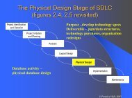
System/framework<br />
documentation<br />
Tutorial<br />
documentation<br />
Reference<br />
documentation<br />
Rationale<br />
documentation<br />
Entity-based<br />
Architecture<br />
reference<br />
documentation<br />
documentation<br />
Figure 1. Overview <strong>of</strong> documentation types<br />
With regard to documentation <strong>of</strong> OO s<strong>of</strong>tware systems <strong>and</strong> frameworks, we will distinguish<br />
between the following types <strong>of</strong> documentation:<br />
• Tutorial documentation:<br />
Introductory material for novices.<br />
• Reference documentation:<br />
Ideally, a complete description <strong>of</strong> s<strong>of</strong>tware for experienced users. The reference<br />
documentation is divided into:<br />
• Architecture documentation:<br />
Describing the overall structure <strong>and</strong> transverse relations <strong>of</strong> the system.<br />
• Entity-based reference documentation:<br />
Describing each entity in the system in its own right.<br />
• Rationale documentation:<br />
Discussions <strong>of</strong> design alternatives <strong>and</strong> decisions<br />
Each documentation type will be described in details in the subsequent sections.<br />
The main “clue” in separating the documentation into these four parts is to allow the<br />
reference sections to remain concise. This implies that it is not intended for novices to<br />
the system; hence they need a tutorial. Furthermore, the reference documentation does<br />
not contain the rationale, that is, it describes what but not why, again to make it concise.<br />
The why’s are important, especially for reasons <strong>of</strong> maintenance, <strong>and</strong> are included in the<br />
rationale documentation.<br />
The reference documentation has been split into two, to emphasise that an entity-based<br />
documentation does not suffice. The pragmatic separation between what to document in<br />
the architecture part, <strong>and</strong> the entity part is that we will recommend that the entity based<br />
reference manual is generated by extracting source-code comments, e.g. using JavaDoc.<br />
COT/2-42-V2.4<br />
Page 9/35
Centre for<br />
<strong>Object</strong> Technology<br />
We do not discuss whether the four types <strong>of</strong> documentation should be put in different<br />
sections in one document, or in separate documents. This clearly depends on the tradition<br />
<strong>of</strong> the organisations <strong>and</strong> on the size <strong>of</strong> the system or framework. We will, however,<br />
discuss the advantages that can be obtained by making all the documentation available<br />
online.<br />
Finally, we do not propose that the four types <strong>of</strong> documentation should be m<strong>and</strong>atory<br />
for all kinds <strong>of</strong> s<strong>of</strong>tware. The type <strong>of</strong> documentation required for a s<strong>of</strong>tware package<br />
clearly depends on the kind <strong>of</strong> package (cf. section 1.3) <strong>and</strong> other factors such as the<br />
number <strong>and</strong> type <strong>of</strong> users. A product used by a large number <strong>of</strong> external users clearly<br />
needs more documentation than an application-specific library package used by a small<br />
team working together.<br />
In the following sections, we will provide a detailed description <strong>of</strong> the four types <strong>of</strong><br />
documentation in the following order: tutorial-, rationale-, entity-, <strong>and</strong> architecture<br />
documentation. This order is not a matter <strong>of</strong> priority; in fact we consider the architecture<br />
documentation to be the most difficult part to write because there is no common underst<strong>and</strong>ing<br />
<strong>of</strong> how to structure the architecture documentation. By treating them in this<br />
order, it should be clearer what aspects we do not consider as part <strong>of</strong> the architecture<br />
documentation, in that we recommend that the same aspect is not described twice (at<br />
least not at the same level <strong>of</strong> detail) to minimise redundancy.<br />
4. Tutorial <strong>Documentation</strong><br />
The tutorial is the first introduction to the system. The purpose <strong>of</strong> the tutorial documentation<br />
is to provide developers with an overview <strong>of</strong> the system <strong>and</strong> to present the major<br />
parts <strong>of</strong> the system. Its purpose is not to be complete, but to provide a mental model <strong>of</strong><br />
the system, <strong>and</strong> to give an overview <strong>of</strong> the major architectural characteristics.<br />
We currently know <strong>of</strong> the following kinds <strong>of</strong> tutorial information:<br />
1. Cookbook<br />
A cookbook is a description <strong>of</strong> how to solve typical problems by using a framework<br />
or enhancing a s<strong>of</strong>tware system. An example is the Smalltalk cookbook for covering<br />
almost anything from writing a class to making graphical user interfaces. It can be<br />
seen at:<br />
http://www.objectshare.com/products/smalltalk/vworks/info/cookbook/httoc.htm<br />
2. Textbook<br />
A textbook is a detailed presentation, typically used in a course on a given subject.<br />
This is perhaps the ultimate tutorial documentation. One <strong>of</strong> the first object-oriented<br />
frameworks, the discrete simulation framework DEMOS by Birtwistle [Birtwistle79],<br />
is documented in this manner.<br />
3. Pattern language description<br />
Ralph Johnson’s paper [Johnson92] on using pattern languages to document frameworks.<br />
Only a few examples exist to illustrate the technique. Notice that a pattern<br />
language is only somewhat related to a design pattern. A pattern language is a set <strong>of</strong><br />
COT/2-42-V2.4<br />
Page 10/35
Centre for<br />
<strong>Object</strong> Technology<br />
hints on how to design a thing, <strong>and</strong> how to address problems that typically arise<br />
during the design process, <strong>and</strong> hints on how best to organise one’s work (in which<br />
order to do things) when designing.<br />
4. Concrete examples<br />
This is a collection <strong>of</strong> concrete examples <strong>of</strong> using the system/framework. The examples<br />
should be brief <strong>and</strong> easy to underst<strong>and</strong>. Each example must be annotated in a<br />
fashion that shows what it does <strong>and</strong> how it works. It is important to notice that an<br />
example in this context is not a full application but a small program focusing on illustrating<br />
a specific point.<br />
5. Guided construction tour<br />
This is a complete example <strong>of</strong> how to develop an application by using a set <strong>of</strong> s<strong>of</strong>tware<br />
packages. At the outset, it defines the requirements <strong>of</strong> the application <strong>and</strong> then<br />
proceeds to describe step by step how to develop the application. As opposed to the<br />
concrete examples, the guided tour presents the process as well as the product. Such<br />
guided tours are <strong>of</strong>ten online.<br />
6. FAQ (frequently asked questions)<br />
A FAQ is a list <strong>of</strong> questions <strong>and</strong> answers. The questions have really been asked, <strong>and</strong><br />
the questioner has received an answer that actually helped. The FAQ should be<br />
structured in a fashion that groups together the same types <strong>of</strong> questions/answers.<br />
It is neither necessary (nor recommended) to produce all <strong>of</strong> the above kinds <strong>of</strong> tutorials.<br />
Concrete recommendations will be given in Chapter 10. Conclusions <strong>and</strong> Recommendations.<br />
5. Rationale <strong>Documentation</strong><br />
This documentation contains a description <strong>of</strong> the design choices that resulted in the architecture<br />
<strong>of</strong> the s<strong>of</strong>tware, the choice <strong>of</strong> algorithms, or the selection <strong>of</strong> a 3 rd party packages<br />
to depend on. An important aspect <strong>of</strong> the document is what alternatives were considered,<br />
<strong>and</strong> why they were not chosen. Sometimes one chooses an alternative, which is<br />
not based on any current requirement but on the expectation that requirements <strong>of</strong> a<br />
given type will soon appear. At other times, the best solution for a given requirement is<br />
either not mature or too expensive. Such information should not be intermixed with the<br />
architecture documentation, which is intended to stay concise <strong>and</strong> describe the structure<br />
<strong>of</strong> the system.<br />
The rationale can be formulated as a supplement to the reference documentation, that is,<br />
it follows the structure <strong>of</strong> the reference documentation <strong>and</strong> discusses it in relation to the<br />
documentation. Or a rationale can be structured as a set <strong>of</strong> topics where the discussion<br />
<strong>of</strong> any particular topic contains references to reference sections.<br />
Typically, the rationale explanations will refer back to the requirements to the system.<br />
We believe that rationale documentation is important to maintain, but it has a long payback<br />
time. The rationale document will keep track <strong>of</strong> why a certain thing was done in<br />
one way or the other. As such, it is an interpretation <strong>of</strong> how to achieve the obligations<br />
from the requirement document. In later extensions to the system, the programmers will<br />
COT/2-42-V2.4<br />
Page 11/35
Centre for<br />
<strong>Object</strong> Technology<br />
then not try out solutions that have already been tried. The rationale documentation<br />
could also be produced as a video recording (see section 9).<br />
The rationale documentation can also play an important role in respect to traceability, as<br />
discussed earlier in section 2.3. Normally traceability can be done by references from<br />
the requirement, but a more extreme position is that the rationale is the exact joint that<br />
explicitly addresses traceability, by deliberating why a given requirement is fulfilled the<br />
way it is.<br />
6. Reference <strong>Documentation</strong><br />
The ideal reference documentation is complete, in the sense that a reader will find the<br />
answer to all structural <strong>and</strong> functional questions regarding the s<strong>of</strong>tware described here.<br />
In practice, this is not possible to achieve, as one must find a reasonable balance between<br />
the cost <strong>of</strong> producing documentation <strong>and</strong> the cost <strong>of</strong> finding answers to questions<br />
regarding the s<strong>of</strong>tware. However, the structure <strong>of</strong> the reference documentation should<br />
make it easy to locate the point where information should be available. It is important to<br />
point out that reference documentation is not intended as introductory material. Reference<br />
documentation is for developers who need answers to specific questions.<br />
6.1 Entity-based Reference <strong>Documentation</strong><br />
Entity-based documentation is documentation associated with concrete entities in the<br />
s<strong>of</strong>tware. An entity can for example be a package, a class, a procedure, a task/process,<br />
etc. In principle, entity-based documentation should be extracted from the s<strong>of</strong>tware by<br />
appropriate tools (see section 8.1). Some information is directly available from the syntactic<br />
structure <strong>of</strong> the code <strong>and</strong> other information needs to be supplied by the programmer<br />
as comments.<br />
We propose that the programmer provide the following information as comments in the<br />
source code:<br />
• Responsibility (package or class).<br />
Describes the overall purpose <strong>and</strong> rationale for the given item (package or class).<br />
A one line description, <strong>and</strong> if necessary an extended description.<br />
• Functionality (operations).<br />
Both a one line description <strong>and</strong> an extended description. The extended version includes<br />
a description <strong>of</strong> parameter usage <strong>and</strong> return values, <strong>and</strong> the conditions in<br />
which exceptions are raised.<br />
• Invariant (package <strong>and</strong> class).<br />
Aspects <strong>of</strong> the class that must always be true between calls. This is typically a relationship<br />
between its attributes.<br />
• Pre- <strong>and</strong> post conditions (operations).<br />
What does this operation expect in order to function, both in its parameters <strong>and</strong> in<br />
the state <strong>of</strong> the object in which the operation is located, <strong>and</strong> what does the operation<br />
promise to be true afterwards. Pre/Post conditions are important tools in contractbased<br />
design [Meyer97].<br />
• Type information<br />
COT/2-42-V2.4<br />
Page 12/35
Centre for<br />
<strong>Object</strong> Technology<br />
This is intentional information that may not be extracted from the source code itself,<br />
e.g. exception class, abstract class. This is only necessary for some languages, i.e.<br />
Beta unifies many mechanisms in the pattern construct, but the programmer uses the<br />
pattern as a class or procedure. Java <strong>and</strong> C++ has syntax for most types, Smalltalk<br />
does not syntactically differentiate between normal classes <strong>and</strong> abstract classes.<br />
• Extensibility requirements<br />
The extensibility requirements are specifications <strong>of</strong> how classes <strong>of</strong> a framework<br />
should be specialised. For a (white box) framework, it should be documented if a<br />
class may be specialised <strong>and</strong> to what extent a procedure may be redefined/specialised.<br />
Often this is covered by tutorial information. However, a systematic<br />
description is required. It is important to distinguish between methods that must<br />
be specialised for the application to function, <strong>and</strong> methods that may be specialised.<br />
In some languages, there are syntactic differences between these two (C++ pure<br />
virtual functions, Java abstract methods). It is also important to know if the method<br />
is intended to be called by the application code, or if it is called as the result <strong>of</strong> some<br />
internal action in the framework.<br />
Contents<br />
Packages <strong>and</strong> classes, but not attributes or methods.<br />
Package 1 “name”<br />
Responsibilities<br />
Class 1 “name”<br />
Type information<br />
Responsibilities<br />
Inherits from<br />
Implements interfaces<br />
Invariant<br />
Public interface:<br />
Attribute 1 “name”<br />
Purpose<br />
Attribute n “name” …<br />
Method 1 “name” (parameters): return value<br />
Functionality<br />
Pre/post conditions<br />
Extensibility requirements<br />
Method m “name” …<br />
Protected interface:<br />
…<br />
Private interface:<br />
…<br />
Class n “name” …<br />
Package 2 “name”<br />
…<br />
Package n “name”<br />
…<br />
Identifier index<br />
Sorted lexicographically<br />
Figure 2. Example <strong>of</strong> entity documentation<br />
This outline corresponds to what the typical tools can generate automatically, although<br />
it requires careful consideration to get the proper layout <strong>of</strong> responsibilities <strong>and</strong> other<br />
documentation. The identifier index is a very convenient aspect <strong>and</strong> must be generated<br />
automatically. A typical entry will have the structure <strong>of</strong> “name:class:package”, thereby<br />
making it easy for the user to find a specific entry, e.g. to find an update method in the<br />
right class. Similarly, the content part is necessary for large systems in order to navigate<br />
quickly to the appropriate class.<br />
COT/2-42-V2.4<br />
Page 13/35
Centre for<br />
<strong>Object</strong> Technology<br />
Please note that the inclusion <strong>of</strong> attributes in the public interface does not signify that all<br />
attributes should be public, but that sometimes it is part <strong>of</strong> the model that attributes can<br />
be accessed <strong>and</strong> manipulated directly. This corresponds to the choices in Java <strong>and</strong> C++<br />
where attributes can be declared public. The private interface is included in the outline<br />
because maintainers need it. If the outline is intended for using the class as a server,<br />
neither the protected, nor the private interface should be part <strong>of</strong> the entity documentation.<br />
The physical layout <strong>of</strong> the entity documentation will be different for paper <strong>and</strong> for a<br />
web-based version. The web-based version will have links from the content section <strong>and</strong><br />
from the index <strong>and</strong> should contain cross-references, for example, to be able to easily<br />
browse to the class defined as a return type <strong>of</strong> a given method.<br />
Appendix A. contains the background for which elements to document in the entity<br />
documentation. It is based on the IEEE st<strong>and</strong>ard on documentation [IEEE-std1016-<br />
1998], <strong>and</strong> the report [MJII-MIA-90-1].<br />
6.2 Architecture <strong>Documentation</strong><br />
In order to underst<strong>and</strong> a system or framework, it is necessary to underst<strong>and</strong> how groups<br />
<strong>of</strong> logically related entities work together. The architecture documentation describes<br />
such related sets <strong>of</strong> entities, whereas the entity documentation describes the entities in<br />
isolation. The architecture documentation should describe the following properties:<br />
• Relation between multiple entities:<br />
Classification (inheritance), composition, associations, etc.<br />
• Interaction between entities:<br />
Active objects/processes, communication <strong>and</strong> synchronization between processes,<br />
shared objects, object states, calling sequence, etc.<br />
• Physical deployment <strong>of</strong> entities on the hardware.<br />
• Organization <strong>of</strong> entities in the development environment:<br />
The static organization <strong>of</strong> the entities in terms <strong>of</strong> directories, files, etc.<br />
• Organization <strong>of</strong> entities in the target environment:<br />
How are objects <strong>and</strong> functions packed in terms <strong>of</strong> executables, link modules <strong>and</strong>/or<br />
binary components.<br />
• Architecture goals <strong>and</strong> constraints [RUP-SAD-Artefact]<br />
Requirements <strong>and</strong> objectives that have a significant impact on the architecture: use<br />
<strong>of</strong>f-the-shelf product, portability, distribution <strong>and</strong> reuse. It also captures special constraints<br />
such as: design <strong>and</strong> implementation strategy, development tools, team<br />
structure, schedule, legacy code, etc.<br />
Each <strong>of</strong> the above aspects will be further elaborated in the sections to follow.<br />
Examples <strong>of</strong> architecture documentation:<br />
• Description <strong>of</strong> a set <strong>of</strong> entities using UML such as package diagrams, class diagrams,<br />
state machines, sequence diagrams, etc., accompanied by a textual description<br />
<strong>of</strong> the relations.<br />
COT/2-42-V2.4<br />
Page 14/35
Centre for<br />
<strong>Object</strong> Technology<br />
• <strong>Documentation</strong> <strong>of</strong> the Danfoss Instruments USM II framework. Here the logically<br />
related elements <strong>of</strong> the USM II framework are grouped into so-called patterns 1 , <strong>and</strong><br />
each pattern is documented by using a number <strong>of</strong> different UML diagrams accompanied<br />
by textual descriptions.<br />
In [MJII-MIA-90-1] the term configuration covers a group <strong>of</strong> logically related entities<br />
<strong>and</strong> it is proposed to identify such configurations <strong>and</strong> to document the relations between<br />
its entities, <strong>and</strong> to document the relationship with other configurations. It is proposed to<br />
structure the architecture document as a set <strong>of</strong> hierarchically organised configurations.<br />
Section 2.2 provides some general guidelines to be considered when writing architecture<br />
documentation. Section 6.2.1 presents an approach to documenting an architecture<br />
that takes its outset in documenting the configurations <strong>of</strong> a program.<br />
In the USM II framework, the term pattern is used for the logically related entities being<br />
documented. The term pattern is, however, mainly used for well-established mini architectures<br />
that have proved their usefulness in several cases. A configuration that turns<br />
out to be reused in several contexts may evolve into a pattern.<br />
Disclaimer: The structure <strong>and</strong> contents <strong>of</strong> the architecture documentation have not yet<br />
been verified experimentally to be an effective way to describe the architecture <strong>of</strong> a<br />
system. However, it is the best recommendation that we can provide at the time <strong>of</strong><br />
writing.<br />
6.2.1 Documenting Configurations<br />
At the top level, the system may be divided into configurations that are subsystems, <strong>and</strong><br />
each subsystem may in turn be divided into further subsystems. In some situations the<br />
configurations may correspond to a subsystem division <strong>of</strong> the system/framework, in<br />
other situations it may be necessary to identify a number <strong>of</strong> configurations within the<br />
same subsystem. A class/object may play a role in more than one configuration. When a<br />
system/framework is documented using design patterns, a class/object may also appear<br />
in more than one pattern.<br />
The following means may be used in the architecture documentation:<br />
• Established patterns:<br />
It is attractive to use design patterns 2 to document configurations. A pattern <strong>and</strong> a<br />
configuration are very similar, as they both constitute a group <strong>of</strong> logically related<br />
classes/objects. When a configuration is an established pattern, or be inspired by one<br />
or more patterns, relating the configuration to this/these patterns makes the system<br />
easier to underst<strong>and</strong>.<br />
• Diagram types:<br />
• As already mentioned, diagrams are useful when documenting configurations. In<br />
general, there should be no m<strong>and</strong>atory rules for which diagrams to use since<br />
diagrams should only be used if they contribute useful information. In addition<br />
to diagrams, it may also sometimes be a good idea to use abstract algorithms. In<br />
general, any kind <strong>of</strong> picture, diagram <strong>and</strong> other notation useful for documenting<br />
1 The term pattern used in the USM II document is not always in accordance with the common use <strong>of</strong> the<br />
term design pattern.<br />
2 That is, design patterns in the form presented in [Gamma95].<br />
COT/2-42-V2.4<br />
Page 15/35
Centre for<br />
<strong>Object</strong> Technology<br />
a given configuration should be used. It is important that the description is concise<br />
<strong>and</strong> underst<strong>and</strong>able. For reasons <strong>of</strong> consistency it is <strong>of</strong> course a good idea to<br />
use a common notation as much as possible. UML is an obvious notation c<strong>and</strong>idate<br />
in most cases but may be insufficient in special situations.<br />
• Natural Language:<br />
No diagram or design pattern can st<strong>and</strong> alone, but should always be accompanied by<br />
an explanatory text. Sometimes a configuration is also <strong>of</strong> such a nature that it requires<br />
an explanation, which is not best described by a st<strong>and</strong>ard UML diagram, but<br />
through a free figure.<br />
6.2.2 Structuring the Architecture <strong>Documentation</strong><br />
The purpose <strong>of</strong> the architecture documentation is to document the structure <strong>of</strong> the system/framework.<br />
As mentioned earlier, we have not surveyed different approaches to<br />
documenting architecture in great depth. The “4+1” view proposed by [Kruchten95] <strong>and</strong><br />
later updated in [Kruchten98] has been the main inspiration for our proposal on how to<br />
structure the documentation <strong>of</strong> a configuration – that is a configuration used in the sense<br />
described above, as sets <strong>of</strong> logically interrelated entities. The main idea that we borrow<br />
from the “4+1” view is that there are multiple views from which a system should be<br />
documented, <strong>and</strong> that these views should be tied together by relating them directly to<br />
their requirement – the “+1” view.<br />
We propose a model with three main views: Requirement view, conceptual view <strong>and</strong><br />
realisation view, as these views are m<strong>and</strong>atory in all systems.<br />
Conceptual<br />
View<br />
Requirement<br />
View<br />
Realization<br />
View<br />
Figure 3. A model with three views<br />
• Requirement view:<br />
For a given configuration there is a set <strong>of</strong> requirements that motivates its existence.<br />
These requirements can be in the form <strong>of</strong> a set <strong>of</strong> Use Cases/scenarios representing<br />
all possible uses <strong>of</strong> the configuration. The description <strong>of</strong> the scenarios may be in<br />
terms <strong>of</strong> sequence diagrams <strong>and</strong>/or object diagrams. But not all configurations are<br />
motivated by customer requirements, some exist due to decisions made during design,<br />
because <strong>of</strong> lack <strong>of</strong> time for anything better, or because someone think it will<br />
improve the s<strong>of</strong>tware in some way. The requirement view can be seen as an explicit<br />
method <strong>of</strong> ensuring reverse traceability.<br />
• Conceptual View:<br />
The conceptual view presents the architecture <strong>of</strong> a configuration from a logical point<br />
<strong>of</strong> view, which includes the static properties such as classes, inheritance, associations,<br />
etc. It also includes the dynamic properties such as state machine, object in-<br />
COT/2-42-V2.4<br />
Page 16/35
Centre for<br />
<strong>Object</strong> Technology<br />
teraction <strong>and</strong> domain intrinsic concurrency. To document the conceptual view, the<br />
following aspects/sub-views may be relevant:<br />
• Package View: If many classes are present they may have to be organised in<br />
packages.<br />
• Class View: This view describes classes/objects, inheritance relations, composition,<br />
associations, etc.<br />
• State machines: For classes with a state machine, State Charts may be included<br />
to document the state dependent behaviour 3 .<br />
• Behavioural View: Concurrency in the form <strong>of</strong> active objects/processes should<br />
be documented, which may be carried out by using class or object diagrams with<br />
active classes or objects as well as UMLs sequence- or collaborations diagrams.<br />
But also non-trivial sequential behaviour, especially division <strong>of</strong> labour between<br />
a number <strong>of</strong> objects, should be documented. Again sequence- or collaboration<br />
diagrams are valuable tools.<br />
In many contexts a conceptual view is <strong>of</strong>ten referred to as a logical model, an<br />
analysis model or design model.<br />
• Realisation View:<br />
The realisation view documents various aspects <strong>of</strong> the implementation <strong>of</strong> the conceptual<br />
view/model. The following views may be relevant:<br />
• Source Code View: This view describes the static organisation <strong>of</strong> the s<strong>of</strong>tware<br />
in terms <strong>of</strong> files <strong>and</strong> directories, etc. (e.g. with a UML component diagram).<br />
• Executable View: This view describes the packaging <strong>of</strong> the s<strong>of</strong>tware elements<br />
into components delivered to the customer. The s<strong>of</strong>tware may be delivered as<br />
one or more executables, code libraries, etc. In a setting with Micros<strong>of</strong>t COM<br />
binary components, the view should describe how the elements <strong>of</strong> the conceptual<br />
model are packed onto binary components (e.g. with a UML component<br />
diagram).<br />
• Process View: This view addresses the concurrent aspects <strong>of</strong> the system at runtime<br />
i.e. tasks, threads or processes <strong>and</strong> their interactions.<br />
• Deployment View: This view describes the computers in the system <strong>and</strong> connected<br />
Hardware devices <strong>and</strong> the mapping <strong>of</strong> the conceptual model on these<br />
computers. This view can also be used to show the mapping <strong>of</strong> the concurrent<br />
processes onto nodes in a distributed system (e.g. with a UML deployment diagram).<br />
• Data View: the mapping <strong>of</strong> parts <strong>of</strong> the conceptual model onto secondary storage.<br />
This mapping may describe which objects are persistent <strong>and</strong> how they are<br />
mapped into a traditional relational database, etc.<br />
• Performance view: Sometimes a configuration must perform within critical<br />
limits, it might be time or space that it the limiting factor. The performance <strong>of</strong><br />
the entities might be critical, <strong>and</strong> one needs to document average or worst-case<br />
consumption.<br />
The realisation view is also referred to as the physical model (opposed to the logical<br />
model).<br />
3 Notice that state machines are for a single class only, <strong>and</strong> could therefore be part <strong>of</strong> the entity manual.<br />
However, we want the entity manual to be extracted from an annotated source code, <strong>and</strong> it is not clear that<br />
it is practical to specify the state machine in a source code comment.<br />
COT/2-42-V2.4<br />
Page 17/35
Centre for<br />
<strong>Object</strong> Technology<br />
One <strong>of</strong> the difficult problems in writing the reference document for the s<strong>of</strong>tware architecture<br />
is the requirement that it should be complete – complete in relation to what? One<br />
<strong>of</strong> the most attractive aspects <strong>of</strong> the “2+1” approach is that it allows us to define the<br />
completeness in relation to requirements. Each configuration addresses a number <strong>of</strong> requirements,<br />
<strong>and</strong> the architecture documentation is complete when all requirements (both<br />
customer <strong>and</strong> internal requirements) are covered.<br />
It is also worth to notice that the relevance <strong>of</strong> a view depends on the abstraction level.<br />
E.g. at a detailed level, the entire realisation view might be implicit from the hierarchical<br />
structure <strong>of</strong> the system. Our recommendation is to really have good reasons to<br />
eliminate one <strong>of</strong> the three main views, conceptual, realisation or requirement, but feel<br />
free in which <strong>of</strong> the sub-views are used. The choice <strong>of</strong> sub-views depends on both the<br />
abstraction level <strong>and</strong> on the size <strong>and</strong> complexity <strong>of</strong> the system/framework to be documented.<br />
Appendix B. contains a comparison between our “2+1” model <strong>and</strong> the original “4+1”<br />
proposed by Kruchten.<br />
6.2.3 Hierarchical Design Descriptions<br />
The configurations should be organised hierarchically, which should be reflected in the<br />
documentation. The top-level configuration should give an overview <strong>of</strong> the architecture.<br />
More detailed descriptions should be given for each sub-configuration, <strong>and</strong> subconfigurations<br />
should then be organised into new sub-configurations, etc. At present, it<br />
is difficult to advice on this part, since we have only little experience.<br />
Figure 4 shows a proposal for concrete document types <strong>and</strong> their relations based on the<br />
information presented in the previous sections. The figure shows also an example <strong>of</strong><br />
how a concrete documentation may be organized. Solid lines represent hierarchical decomposition,<br />
with the lower nodes being subordinate to the higher nodes. In this concrete<br />
example, the s<strong>of</strong>tware consists <strong>of</strong> five classes in two packages, each class with one<br />
attribute <strong>and</strong> two methods. The architecture documentation consists <strong>of</strong> three top-level<br />
configurations, <strong>of</strong> which the middle configuration consists <strong>of</strong> two configurations etc.<br />
(Please note that it is unrealistic to have this many configurations for so few s<strong>of</strong>tware<br />
entities). The special symbol within each configuration indicates that the configuration<br />
is documented by using the “2+1” principle discussed in the previous section.<br />
COT/2-42-V2.4<br />
Page 18/35
Centre for<br />
<strong>Object</strong> Technology<br />
Reference document<br />
Entity document<br />
Architecture document<br />
Package<br />
Package<br />
Config<br />
Config<br />
Config<br />
System<br />
Architecture<br />
<strong>Documentation</strong><br />
Attribute<br />
Class<br />
Method<br />
Attribute<br />
Class<br />
Method<br />
Config<br />
Config<br />
Method<br />
Method<br />
Class<br />
Class<br />
Attribute<br />
Method<br />
Attribute<br />
Method<br />
Config Config Config Config<br />
Method<br />
Method<br />
Class<br />
Config<br />
Config<br />
Component<br />
Design<br />
<strong>Documentation</strong><br />
Attribute<br />
Method<br />
Method<br />
Config<br />
Config<br />
Config<br />
Config<br />
Figure 4. <strong>Documentation</strong> example<br />
Figure 4 also illustrates the possible cross-references between the configuration documentation<br />
<strong>and</strong> the entity documentation. A given configuration can refer to several sections<br />
in the entity documentation, for instance to avoid repetition <strong>of</strong> parameters, preconditions<br />
etc. A given entity can play several configuration roles, thus relieving the<br />
entity-documenter <strong>of</strong> explaining those aspects in detail.<br />
In the working group we have at numerous occasions discussed the difference or similarity<br />
between, what is sometimes referred to as system architecture documentation <strong>and</strong><br />
component design documentation. The argument for a distinction is that there are important<br />
decisions to document for the entire system, <strong>and</strong> it is advisable to locate them<br />
explicitly in a top-level architecture document. Arguments to the contrary are that, at<br />
any level <strong>of</strong> a system, there will be important design decisions to be made for the entire<br />
subsystem. Hence there are no structural difference between the kind <strong>of</strong> documentation<br />
required for a full system <strong>and</strong> that required for a subsystem. The compromise represented<br />
in the figure is that some <strong>of</strong> the top-level configuration descriptions are referred<br />
to as system architecture documentation, while the rest are referred to as component design<br />
documentation. In our opinion it is a fruitful distinction, but we also find that it is<br />
difficult to set up precise rules as to when a configuration is part <strong>of</strong> the system architecture<br />
<strong>and</strong> when it is part <strong>of</strong> the component design.<br />
COT/2-42-V2.4<br />
Page 19/35
Centre for<br />
<strong>Object</strong> Technology<br />
7. <strong>Documentation</strong> in the Development Process<br />
It is an overall goal for system documentation that it should be useful for both s<strong>of</strong>tware<br />
developers <strong>and</strong> maintainers <strong>of</strong> s<strong>of</strong>tware systems.<br />
7.1 Waterfall Development<br />
The traditional waterfall development process is usually document-driven, <strong>and</strong> the milestone<br />
<strong>of</strong> each development phase has normally been a reviewed <strong>and</strong> approved document<br />
for a particular phase. Document examples are requirement specification documents,<br />
system design documents etc. Another characteristic would be that the output <strong>of</strong> each<br />
development phase has been used as input for the next phase. The waterfall model approach<br />
has the advantage that the documentation is produced during the development<br />
process because it is required for finalising a given milestone <strong>and</strong> used as input to the<br />
following phase. Verification is normally done through a more or less formal review or<br />
inspection <strong>of</strong> the document.<br />
The st<strong>and</strong>ard critique against the waterfall model is that all phases are executed sequentially,<br />
feedback comes very late before the implementation <strong>and</strong> integration test prove, or<br />
more normally find, flaws, errors <strong>and</strong> inefficiencies in the design. When feedback occurs,<br />
the design should be revised <strong>and</strong> all the documents should be updated, <strong>and</strong> it may<br />
then be necessary to carry out a new review. As these deficiencies are detected very late<br />
in the development process (if the method is followed strictly), corrections are made in<br />
the code only, without the corresponding document updates (because it becomes too<br />
expensive to return to earlier phases <strong>of</strong> the development). As a consequence, the documentation<br />
cannot be used for maintenance, as it does not correspond to the running code<br />
any more. It should be noted that in practice the waterfall model is not strictly followed<br />
because <strong>of</strong> these reasons.<br />
7.2 Iterative Development<br />
Modern development methods suggest an iterative <strong>and</strong> incremental development process.<br />
An example here<strong>of</strong> is the Unified S<strong>of</strong>tware Development Process [Jacobson99] in<br />
which iterations are planned <strong>and</strong> driven by the identified Use Cases. This approach has<br />
been tested in the COT/Case 2 pilot projects where it was an effective <strong>and</strong> more flexible<br />
way <strong>of</strong> developing s<strong>of</strong>tware compared to the traditional waterfall model.<br />
7.2.1 <strong>Documentation</strong> Process<br />
The question is how the documentation is produced in an iterative development process<br />
<strong>and</strong> how this process changes the way <strong>of</strong> working with documentation.<br />
The documentation structure for the project must be defined before starting development–because<br />
documentation plays a very active role in the process. The documentation<br />
structure must be supported with concrete document templates for the different artefacts–this<br />
could be st<strong>and</strong>ard templates or templates adjusted for the specific project.<br />
COT/2-42-V2.4<br />
Page 20/35
Centre for<br />
<strong>Object</strong> Technology<br />
However, the documentation structure is also part <strong>of</strong> the iterative development, hence<br />
the structure <strong>of</strong> the documentation can also be made subject for redesign.<br />
If the requirement specification is specified with the Use Case technique [Jacobson99]<br />
these Use Cases are used as the basis for planning the iterations. Detailed guidelines for<br />
planning this iteration are described in [Jacobson99].<br />
The Use Cases selected for the first iteration must cover some <strong>of</strong> the architectural significant<br />
Use Cases or the main scenarios here<strong>of</strong>. <strong>Object</strong>-oriented analysis <strong>and</strong> design<br />
models are developed for these Use Cases <strong>and</strong> the different document templates are<br />
filled with the information required to describe the state <strong>of</strong> the project. An (informal)<br />
review could verify the architectural ideas before implementing the actual iteration.<br />
The different documents are only partly finished with the documentation for a given iteration<br />
<strong>and</strong> subsequently enhanced with information from following iterations. This<br />
produces a very dynamic document, which is updated after the completion <strong>of</strong> each iteration.<br />
In this way a given document plays a very active role in the development process<br />
as it is updated on an ongoing basis to correspond exactly to the running code.<br />
In this iterative process, the important milestones are designed <strong>and</strong> implemented parts <strong>of</strong><br />
the system where the errors have been corrected. The approval <strong>of</strong> a milestone can include<br />
the updating <strong>of</strong> documentation, which could be either formally or informally reviewed<br />
in a normal review process.<br />
In the next iteration, the documents are enlarged by the introduction <strong>of</strong> new development<br />
information for the corresponding Use Cases for this iteration.<br />
7.2.2 “2+1” View Model – as Process Driver<br />
The concept behind the “2+1” view model with different development views can also be<br />
used as a driver in the process for developing the system architecture.<br />
One <strong>of</strong> the first tasks in a project is to select the number <strong>of</strong> relevant views for the given<br />
project. As an example, a project specified to run on one computer will not have a deployment<br />
view, <strong>and</strong> a sequential programme will not have a process view. The next task<br />
is to define or adjust the document structure <strong>and</strong> the corresponding document templates<br />
to the needs <strong>of</strong> the actual project.<br />
After selecting one or more Use Cases for the actual iteration, the corresponding objectoriented<br />
models are developed <strong>and</strong> documented in the logical view.<br />
The next step is to develop the first version <strong>of</strong> the other views based on the information<br />
in the logical view. The executable- <strong>and</strong> source code view is developed for defining a<br />
layered model <strong>of</strong> source code components. The deployment view is developed for defining<br />
the actual computers/processors <strong>and</strong> hardware devices. If the system can be installed<br />
in different configurations this is taken into account <strong>and</strong> documented. If the Use<br />
Cases have concurrent aspects a first cut <strong>of</strong> the process view is developed.<br />
COT/2-42-V2.4<br />
Page 21/35
Centre for<br />
<strong>Object</strong> Technology<br />
The logical view can in many situations be adjusted or updated based on the knowledge<br />
gained by looking at the other views with the advantage <strong>of</strong> an easier traceability from<br />
the conceptual view to the other views.<br />
By looking at the different aspects <strong>of</strong> each view, the architecture <strong>of</strong> the programme will<br />
be formed stepwise as well as the corresponding achitecture documentation. The actual<br />
development iteration can now be designed in detail, implemented <strong>and</strong> tested.<br />
The next iteration will proceed in the same way with selection <strong>of</strong> some new Use Cases<br />
<strong>and</strong> developing or updating the different views based on these new requirements. By<br />
carefully selection <strong>of</strong> the Use Cases for the first number <strong>of</strong> iterations the architecture <strong>of</strong><br />
the programme will begin to stabilise.<br />
The template for an architecture document could have sections corresponding to the different<br />
views as each <strong>of</strong> these views have different stakeholders. In this way a step in the<br />
development process could be to develop a given view <strong>and</strong> fill out the corresponding<br />
section in the architecture document template.<br />
8. Tool Support for <strong>Documentation</strong><br />
A number <strong>of</strong> artefacts are produced in the development process. They may be textual,<br />
e.g. natural language descriptions or source-code or graphical descriptions like Use<br />
Cases, class diagrams, sequence diagrams, state-transition diagrams but they are not<br />
necessarily limited to texts <strong>and</strong> diagrams. In the pilot projects we have also used white<br />
board snapshots, i.e. photographic pictures <strong>of</strong> the white board, to capture more or less<br />
informal information. Descriptions are produced using different tools, e.g. a CASE tool<br />
for producing diagrams, <strong>and</strong> text editors for producing source code. The source code<br />
may be generated from the models in the CASE tool, or the diagrams may be generated<br />
from the source code or a mixture <strong>of</strong> both. Initially the primary purpose <strong>of</strong> producing<br />
the development artefacts was to support the analysis, design <strong>and</strong> implementation processes.<br />
However, many <strong>of</strong> the same artefacts are also used in the system documentation. This<br />
chapter discusses tool support for producing the kind <strong>of</strong> documentation discussed so far<br />
in the report.<br />
In an iterative <strong>and</strong> incremental development process, not only the final system but also<br />
the intermediate states <strong>of</strong> the system needs to be documented. Tools should support the<br />
documentation needs in these intermediate states as well as the final documentation.<br />
COT/2-42-V2.4<br />
Page 22/35
Centre for<br />
<strong>Object</strong> Technology<br />
Reference documentation<br />
Tutorial<br />
document a tion<br />
Entity-based<br />
reference<br />
docume n tation<br />
Architecture<br />
documentation<br />
Rationale<br />
document a tion<br />
Development artefacts<br />
Source<br />
code<br />
Di a grams<br />
Model<br />
i n formation<br />
Whiteboard<br />
snapshots<br />
Automatic generation<br />
Insertion (copy or link)<br />
Figure 5. <strong>Documentation</strong> types <strong>and</strong> examples <strong>of</strong> development artefacts<br />
In Figure 5, the types <strong>of</strong> documentation (that this report focuses on) are illustrated in the<br />
upper part <strong>of</strong> the diagram: tutorial documentation, reference documentation <strong>and</strong> rationale<br />
documentation. The lower part <strong>of</strong> the diagram illustrates some <strong>of</strong> the development<br />
artefacts: source code, diagrams, model information, <strong>and</strong> whiteboard snapshots. Model<br />
information refers to the model representation in a tool, typically a CASE tool. This information<br />
may be redundant, but it can also be information, which is not contained in<br />
the source code or the diagrams. One example is the Use Case descriptions produced in<br />
a CASE tool or in a word processor. Depending on the tools used, the model information<br />
may be non-existent. In the pilot projects, two different approaches were used for<br />
the responsibility descriptions. In some cases they were entered in the CASE tool <strong>and</strong> in<br />
other cases directly in the source code.<br />
The arrows indicate the possible relationships between the documentation types <strong>and</strong> the<br />
development artefacts:<br />
• Automatic generation <strong>of</strong> the entity-based reference documentation.<br />
• Insertion (copy or link). Use <strong>of</strong> development artefacts in the documentation.<br />
The two types <strong>of</strong> relationships will be discussed below.<br />
COT/2-42-V2.4<br />
Page 23/35
Centre for<br />
<strong>Object</strong> Technology<br />
8.1 Automatic Generation <strong>of</strong> the Entity-based Reference<br />
<strong>Documentation</strong><br />
The entity-based reference documentation can be (<strong>and</strong> should be) tool generated, based<br />
on the annotations within the source code <strong>of</strong> the program. The documentation generator<br />
will <strong>of</strong>ten be able to analyse the overall aspects <strong>of</strong> the programming language <strong>and</strong> provide<br />
appropriate information on inheritance, types <strong>of</strong> parameters etc., thus avoiding that<br />
it is written twice (i.e. in the program <strong>and</strong> in the documentation comments).<br />
Figure 6. A screen dump from George<br />
Tools like [JavaDoc] for Java, [George] <strong>and</strong> [BumbleBee] for C++ can generate the entity-based<br />
documentation. These tools are based on the proximity principle, which<br />
means that the code <strong>and</strong> its documentation are so closely connected that the programmer<br />
is likely to update the documentation when the program is changed. When the source<br />
code is changed, the entity-based reference documentation can automatically be regenerated.<br />
Proximity does not solve the problem <strong>of</strong> consistency, but experience shows that<br />
it helps in keeping the entity-based documentation consistent with the implementation.<br />
A screen dump from George is shown in Figure 6. In the example, the constructors <strong>and</strong><br />
member functions <strong>and</strong> their responsibilities are shown for a class called 'Car'. In addi-<br />
COT/2-42-V2.4<br />
Page 24/35
Centre for<br />
<strong>Object</strong> Technology<br />
tion there are links to an overview description <strong>of</strong> the 'Car' <strong>and</strong> to two related classes:<br />
'Person' <strong>and</strong> 'Vehicle'.<br />
8.2 Use <strong>of</strong> Development Artefacts in <strong>Documentation</strong><br />
<strong>Documentation</strong><br />
Diagrams<br />
Model<br />
information<br />
Source<br />
code<br />
Figure 7. Use <strong>of</strong> development artefacts in the documentation<br />
Parts <strong>of</strong> the different development artefacts are likely to be used in the tutorial, the architecture<br />
documentation <strong>and</strong> the rationale. Tool support for automatic insertion <strong>of</strong> these<br />
descriptions in the documents is desirable for at least two reasons:<br />
• It facilitates the collection <strong>of</strong> all the different descriptions into one or more complete<br />
documents,<br />
• New versions <strong>of</strong> documentation have to be produced repeatedly in the development<br />
process, especially in an iterative development process. Automatically inserting<br />
updated information in the documents makes it easier to spot inconsistent<br />
explanations during review.<br />
Some CASE tools provide report generators, which allow the users to produce userdefined<br />
documents that combine textual descriptions with development artefacts. Examples<br />
are model information, diagrams <strong>and</strong> source code. After the report structure has<br />
been defined, the collection <strong>of</strong> relevant development artefacts is simply a matter <strong>of</strong><br />
pressing a button. However, it is important to control the report generation in detail with<br />
regard to what kind <strong>of</strong> information should be included.<br />
In the pilot projects, the best example <strong>of</strong> a report generator that used development artefacts<br />
in the documentation was [QualiWare]. However, the word processor used in<br />
QualiWare is an internal tool <strong>and</strong> the report is therefore not easily integrated with other<br />
documents. HTML generation is another possibility but we have no experience with this<br />
facility.<br />
Rational SoDA (S<strong>of</strong>tware <strong>Documentation</strong> Automation) [SoDA] is a tool that adds<br />
document generation to Micros<strong>of</strong>t Word or Adobe FrameMaker+SGML, <strong>and</strong> enables<br />
information to be extracted from multiple information sources such as Rational Rose.<br />
We have no experience with SoDA, but it could be interesting to investigate further.<br />
COT/2-42-V2.4<br />
Page 25/35
Centre for<br />
<strong>Object</strong> Technology<br />
There are other ways <strong>of</strong> integrating text documentation with information from the<br />
CASE tool or development system. Modern document architecture technologies like<br />
[Micros<strong>of</strong>t COM] enables documents, or parts <strong>of</strong> documents, to be embedded in the<br />
document from other applications. If, for example, the word processor <strong>and</strong> the CASE<br />
tool support [ActiveX], the diagrams or the part <strong>of</strong> the source code could be embedded<br />
in the text document. If the documentation is written in HTML, different scripting languages<br />
like SGI scripts or JavaScript could be used to insert diagrams or parts <strong>of</strong> the<br />
source code. In both instances, additional tool support is desirable.<br />
In general, the optimal solution would be to write documents in a st<strong>and</strong>ard word processor<br />
with inclusion links to diagrams, model information <strong>and</strong> code. Inclusion links are to<br />
be understood as hypertext links where the destination is inserted in the document. By<br />
doing so, the documents could be updated automatically when e.g. the code or the diagrams<br />
are changed. Another challenge would be to support the editing <strong>of</strong> inserted descriptions,<br />
which would then be followed by automatic updating at the source.<br />
Experimenting with all these aspects could be interesting. One experiment could be to<br />
use the Devise hypermedia, which is an open hypermedia system to integrate a word<br />
processor like Word with a CASE tool or other tools <strong>of</strong> a development system.<br />
8.3 Consistency<br />
Above we have seen examples <strong>of</strong> how diagrams, model information <strong>and</strong> source code<br />
can be inserted in the different documents. It is important that the inserted descriptions<br />
are consistent, both mutually <strong>and</strong> with the enclosing text.<br />
8.3.1 Consistency between Development Artefacts <strong>and</strong><br />
<strong>Documentation</strong><br />
The documents may need to be updated when one <strong>of</strong> the development artefacts is<br />
changed. Manual updating, e.g. using copy-paste, should be avoided because it is a error-prone<br />
process where one easily forget to copy exactly what is needed. As described<br />
above, automated updating <strong>of</strong> documents may be carried out differently, but it is important<br />
that the writers <strong>of</strong> the documents are aware <strong>of</strong> the changes, since the explanatory<br />
text may also need to be updated. Such inconsistencies are easier to spot though, than<br />
inconsistencies between an explanation <strong>and</strong> an external (to the document) artefact. The<br />
dependencies between the descriptions must therefore be explicit <strong>and</strong> tool-supported.<br />
For example if a class diagram is changed, the writers <strong>of</strong> the documents, using this diagram<br />
should be notified. The writing the documentation will sometimes result in<br />
changes to the code <strong>and</strong> related descriptions.<br />
8.3.2 Consistency between <strong>Documentation</strong> Types<br />
Neither the architecture documentation nor the tutorial has the same proximity to the<br />
implementation as the entity-based reference documentation. As a result, they are inherently<br />
more prone to inconsistency. Since we also want to avoid redundant descriptions,<br />
it is particularly important to avoid repetition <strong>of</strong> what is described in the entity-based<br />
reference documentation. A tool that allows easy cross-referencing to the entity manual<br />
COT/2-42-V2.4<br />
Page 26/35
Centre for<br />
<strong>Object</strong> Technology<br />
is useful, as it makes it easier for the documenter to avoid redundancies. Currently we<br />
have no recommendations on how best to address this inconsistency problem.<br />
8.3.3 Consistency between Development Artefacts<br />
An important requirement for the CASE tool employed is to ensure mutual consistency<br />
between the inserted descriptions. In the pilot projects we have good experience with<br />
reverse engineering using [Rhapsody] <strong>and</strong> [WithClass]. Reverse engineering <strong>of</strong> the<br />
source code produces class diagrams that are consistent with the code. Class diagrams<br />
illustrate the static properties <strong>of</strong> the system. Sequence diagrams are an example <strong>of</strong> diagrams<br />
that illustrate the dynamic aspects <strong>of</strong> a system. In the COT pilot projects, a tool<br />
[COT/2-27] has been developed for automatic generation <strong>of</strong> sequence diagrams for Java<br />
<strong>and</strong> C++. The sequence diagrams are produced during execution <strong>of</strong> the application <strong>and</strong><br />
this has been a valuable tool in the documentation, verification <strong>and</strong> testing processes.<br />
We have experienced one consistency problem in the COT pilot projects with regard to<br />
responsibility descriptions: Not all CASE tools preserve the annotations in the reverse<br />
engineering process. When using round-trip engineering tools, it is important that all<br />
aspects <strong>of</strong> each representation (i.e. in both CASE tool, <strong>and</strong> in source code) are preserved<br />
when transforming from one representation to the other.<br />
8.4 Links<br />
In general we recommend that documentation is online. Online documentation can provide<br />
much richer navigation facilities that make it easier to home in on the relevant aspect,<br />
especially in large bodies <strong>of</strong> documentation. However, some prefer to read documentation<br />
on paper, especially those aspects <strong>of</strong> the documentation that are not reference<br />
documentation, e.g. the tutorial. We do acknowledge that paper based documents can<br />
contain cross references, but if they are used extensively, the reader soon find them tedious.<br />
But there are advantages in an online tutorial, namely that it can provide links to the reference<br />
documentation. This saves the tutorial writer from repeating what is already in<br />
the reference documentation <strong>and</strong> at the same time teaches the programmer how to use<br />
the reference documentation. If the tutorial is online, the advanced descriptions can also<br />
be moved from the entity-based reference documentation into the tutorial, <strong>and</strong> have<br />
links from the entity based documentation to the tutorial (all the HTML generating<br />
document extractors, we have seen, allow the annotation comments to be full HTML,<br />
including anchors).<br />
The same advantages <strong>and</strong> possibilities for writing tutorials apply to the architecture part<br />
<strong>of</strong> the reference documentation. Descriptions <strong>of</strong> the architecture documentation can<br />
make references to the entity-based reference documentation <strong>and</strong> the entity-based part<br />
can have reference to the architecture part where appropriate, thus avoiding redundancy.<br />
Finally, links in both directions between all the documentation <strong>and</strong> the development artefacts<br />
could be very useful. It will not only help in reading the documentation, but also<br />
in underst<strong>and</strong>ing the implementation <strong>and</strong> in the maintenance <strong>of</strong> the system.<br />
COT/2-42-V2.4<br />
Page 27/35
Centre for<br />
<strong>Object</strong> Technology<br />
If the documentation is written in HTML, the linking facilities <strong>of</strong> HTML can be used.<br />
Many word processors also support hypertext links to some extent. The open hypermedia<br />
system Webwise provides an alternative.<br />
9. Use <strong>of</strong> Videos as <strong>Documentation</strong> Media<br />
In this chapter we will present a general introduction to the use <strong>of</strong> videos as documentation<br />
together with concrete experiences from Danfoss Drives A/S.<br />
An article <strong>of</strong> Tom DeMarco [DeMarco90], who made some experiments in a fast<br />
growing company, inspired the concept <strong>of</strong> using video recordings as documentation<br />
media. The idea was to give new employees a chance to increase productivity by using<br />
video recordings in replacement <strong>of</strong> text-based system documentation. The motivation in<br />
this company to write documents on a working system was low; therefore a quick <strong>and</strong><br />
inexpensive solution was to introduce video recordings. The result was very positively<br />
received, both among the “old” designers telling about the main architecture <strong>and</strong> the<br />
new employees acquiring the knowledge.<br />
Another inspirational source was a lecture held by Alistair Cockburn at a COT seminar<br />
where he compared efficiencies among different communication forms. He claims that<br />
communicating through paper is the slowest <strong>and</strong> least effective medium, whereas video<br />
is the highest achievable communication medium.<br />
Based on these positions, Danfoss Drives decided to proceed with their own experiments,<br />
the situation being that a prototype (non-documented SW) was adopted into a<br />
real project with a strict schedule.<br />
Four video session attempts have been made so far–where a session lasts from 10 minutes<br />
to 1 hour. The experiment had 3 purposes:<br />
1. To inform/teach team colleagues who were not part <strong>of</strong> the pilot project.<br />
2. To archive this information in order to facilitate a subsequent transfer into relevant<br />
documents.<br />
3. The maintainer or reuser could use it later when a speedy introduction to the s<strong>of</strong>tware<br />
is required (tutorial).<br />
Although based on limited experience, some practical conclusions can be made–first <strong>of</strong><br />
all, when presenting a topic it is important to use the whiteboard as much as possible<br />
<strong>and</strong> to minimize the use <strong>of</strong> overhead projectors. An audience should be present during<br />
the session <strong>and</strong> play the role <strong>of</strong> “error filter” <strong>and</strong> partly as a “question generator”. The<br />
tapes should be stored in some sort <strong>of</strong> library after the session <strong>and</strong>, in order to maintain<br />
this library, a person responsible for the video recordings should be assigned.<br />
In order to make the video recordings generally available even for a foreign colleague, it<br />
should be digitised/transferred to a server or at least a CD-ROM. This digitising the<br />
video makes it more useable, as most people will not spend hours in a meeting room<br />
with TV <strong>and</strong> video. In order to make it generally available a video grabber is required<br />
that can store onto a server or a CD-ROM/DVD. However, since this process will re-<br />
COT/2-42-V2.4<br />
Page 28/35
Centre for<br />
<strong>Object</strong> Technology<br />
duce picture quality, it requires that the sessions have large illustrative drawings/texts or<br />
alternatively that detailed drawings can be printed out separately. Whether the present<br />
technology is suitable is still unclear at this point–maybe we have to wait until better<br />
technology like DVD is more mature. It is worth to notice that there are currently a<br />
plethora <strong>of</strong> different file formats <strong>and</strong> video formats, <strong>and</strong> what is best technology today is<br />
hopeless tomorrow.<br />
In general, we believe that video is a good medium to inform about dynamic behaviour<br />
<strong>and</strong> design choices, since these aspects usually are difficult to write in a document. Another<br />
guideline is to use video recordings to capture the original architecture design decisions<br />
made by the leading architect.<br />
We see video primarily as a supplementary technique to produce tutorials <strong>and</strong> rationale.<br />
10. Conclusions <strong>and</strong> Recommendations<br />
The purpose <strong>of</strong> this document has been to provide guidelines for writing documentation<br />
<strong>of</strong> OO s<strong>of</strong>tware. We recommend the following overall guidelines for h<strong>and</strong>ling documentation:<br />
Recommendations regarding the development process:<br />
We assume an iterative strategy where each iteration consists <strong>of</strong> analysis, design,<br />
implementation <strong>and</strong> evaluation. At the end <strong>of</strong> an iteration, the evaluation phase<br />
evaluates the requirements for the iteration <strong>and</strong> new requirements for the next iteration<br />
are defined or selected. These recommendations are similar to those for testing<br />
OO systems [COT-2-43].<br />
• <strong>Documentation</strong> should be an integrated part <strong>of</strong> the development process.<br />
• The architecture <strong>of</strong> the s<strong>of</strong>tware should be reflected in the architecture documentation.<br />
• The structure <strong>of</strong> the architecture <strong>and</strong> architecture documentation should be developed<br />
as part <strong>of</strong> the s<strong>of</strong>tware development process.<br />
• The requirements for the next iteration should specify the parts <strong>of</strong> the architecture<br />
documentation to be delivered.<br />
• Most (all) design documents (class diagrams, state diagrams, etc.) produced<br />
during the development process should be included in the architecture documentation.<br />
• Pictures <strong>of</strong> whiteboard drawings etc. produced during the initial phases are also<br />
c<strong>and</strong>idates be included in the architecture <strong>and</strong> rationale documentation.<br />
Recommendations regarding the form <strong>of</strong> the documentation:<br />
The documentation should be separated into:<br />
• Tutorial documentation.<br />
• Rationale documentation.<br />
• Reference documentation.<br />
• Entity-based reference documentation.<br />
• Architecture documentation.<br />
COT/2-42-V2.4<br />
Page 29/35
Centre for<br />
<strong>Object</strong> Technology<br />
Recommendations regarding tools <strong>and</strong> media:<br />
• Proper tools should be selected in order to provide consistency between the<br />
various parts <strong>of</strong> the documentation <strong>and</strong> to ease construction <strong>and</strong> maintenance.<br />
• The documentation should be generally available.<br />
• To ease availability, online documentation via the Web should be considered.<br />
• Use <strong>of</strong> audio <strong>and</strong> video should be considered. This includes the use <strong>of</strong> multimedia<br />
documents.<br />
Recommendations regarding tutorial documentation:<br />
It is not possible to state absolute requirements since the volume <strong>of</strong> tutorial documentation<br />
required depends on the importance, complexity <strong>and</strong> number <strong>of</strong> s<strong>of</strong>tware<br />
users (i.e. developers)<br />
• Concrete examples are in most cases m<strong>and</strong>atory.<br />
• A FAQ is in most cases m<strong>and</strong>atory.<br />
• In the case <strong>of</strong> s<strong>of</strong>tware frameworks, one <strong>of</strong> 1) Cookbook, 2) Textbook or 3)<br />
Pattern language description is m<strong>and</strong>atory in most cases.<br />
• A guided construction tour is optional but <strong>of</strong>ten a good idea.<br />
Recommendations regarding the rationale:<br />
As for the tutorial documentation it is not possible to state absolute requirements<br />
about the volume <strong>and</strong> content <strong>of</strong> rationale documentation.<br />
• It should be considered to write a rationale for central <strong>and</strong> critical s<strong>of</strong>tware elements.<br />
• The rationale may be used to document design decisions <strong>and</strong> trace original <strong>and</strong><br />
new requirements.<br />
Recommendations regarding the architecture documentation:<br />
As stated previously, architecture documentation is probably the most difficult <strong>and</strong><br />
complicated part <strong>of</strong> the documentation to underst<strong>and</strong>. Again it is difficult to state<br />
absolute requirements for the architecture documentation.<br />
• Architecture documentation may not be required for simple library packages.<br />
• Architecture documentation is required for central <strong>and</strong> complex frameworks, application<br />
packages <strong>and</strong> applications.<br />
• The ideas in the "2+1" view architecture model are recommended, with the main<br />
views as proposed in Figure 3 (i.e. Conceptual, Realisation <strong>and</strong> Use Case<br />
view).<br />
Recommendations regarding the entity-based reference documentation:<br />
• Entity-based documentation is a must.<br />
• Entity-based documentation should be extracted from the (source) code.<br />
The above recommendations are based on experience documented in the literature <strong>and</strong><br />
the authors’ experience from previous projects, including COT. We are, however, not<br />
aware <strong>of</strong> any project that has followed the guidelines exactly as described above. We<br />
hope to be able to test the above guidelines in forthcoming projects.<br />
COT/2-42-V2.4<br />
Page 30/35
Centre for<br />
<strong>Object</strong> Technology<br />
11. References<br />
[ActiveX]<br />
http://www.micros<strong>of</strong>t.com/<br />
[Ada79a]<br />
Preliminary ADA Reference Manual, Sigplan Notices, Vol. 14, No. 6, June<br />
1979, Part A.<br />
[Ada79b]<br />
Rationale for the Design <strong>of</strong> the ADA Programming Language, Sigplan Notices,<br />
Vol. 14, No. 6, June 1979, Part B.<br />
[Bell & Schmidt99]<br />
A.E. Bell, R. W. Schmidt: UMLoquent Expression <strong>of</strong> AWACS S<strong>of</strong>tware Design,<br />
Comm. <strong>of</strong> the ACM, Oct. 1999, Vol. 42, No. 10, (55-61).<br />
[Birtwistle, 1979]<br />
G. M. Birtwistle. A System for Discrete Event Modelling in Simula. Macmillian<br />
Press, 1979.<br />
[BumbleBee]<br />
http://www.bbees<strong>of</strong>t.com<br />
[COT/2-27]<br />
C.J. Andersen: Automatic Generation <strong>of</strong> UML Sequence Diagrams from Java<br />
<strong>and</strong> C++ code. Is planned to be a public COT document later in year 2000.<br />
[COT/2-43]<br />
M.Caspersens, Ole Lehrmann Madsen og Stefan Helleman Skov<br />
Testing <strong>of</strong> object-oriented systems.<br />
[Gamma95]<br />
E.Gamma, R.Helms, R.Johnson, J.Vlissides, Design Patterns – Elements <strong>of</strong> Reusable<br />
<strong>Object</strong>-<strong>Oriented</strong> S<strong>of</strong>tware, Addison-Wesley 1995.<br />
[George]<br />
http://www.k2.co.uk<br />
[IEEE std 1016-1998]<br />
IEEE Recommended Practice for S<strong>of</strong>tware Design Descriptions (SDD). IEEE<br />
st<strong>and</strong>ard 1016-1998<br />
[Jaaksi99]<br />
A.Jaaksi, JM.Aalto, A.Aalto, K.Vättö, Tried & True <strong>Object</strong> Development Industry-Proven<br />
Approaches with UML, Cambridge University Press1999<br />
[Jacobson99]<br />
I.Jacobson, G.Booch, J.Rumbaugh, The Unified S<strong>of</strong>tware Development Process,<br />
Addison-Wesley 1999<br />
[JavaDoc]<br />
http://java.sun.com/products/jdk/javadoc/<br />
[Jensen & Wirth75]<br />
K. Jensen, N. Wirth: Pascal User Manual <strong>and</strong> Report – Second edition,<br />
Springer-Verlag, 1975.<br />
[Johnson92]<br />
R. E. Johnson. Documenting <strong>Frameworks</strong> using Patterns. In OOPSLA'92 Proceedings,<br />
1992.<br />
COT/2-42-V2.4<br />
Page 31/35
Centre for<br />
<strong>Object</strong> Technology<br />
[Kruchten95]<br />
P. Kruchten: The 4+1 View <strong>of</strong> Architecture. IEEE S<strong>of</strong>tware 12,6 (Nov. 1995),<br />
45-50.<br />
[Kruchten98]<br />
P. Kruchten: The Rational Unified Process, Addison Wesley 1998, p83-85.<br />
[Meyer97]<br />
Bertr<strong>and</strong> Meyer: <strong>Object</strong>-<strong>Oriented</strong> S<strong>of</strong>tware Construction, second edition<br />
Prentice Hall, 1997.<br />
[Micros<strong>of</strong>t Com]<br />
http://www.micros<strong>of</strong>t.com/com/<br />
[MjII-MIA-90-1]<br />
J. L. Knudsen et al: Documenting <strong>Object</strong>-<strong>Oriented</strong> <strong>Systems</strong>. Mjølner project II<br />
report, Mjølner Informatics, 1990.<br />
[Rhapsody]<br />
http://www.ilogix.com<br />
[RUP-SAD-artefact]<br />
Rational Unified Process Tool: Artefact for a S<strong>of</strong>tware Architecture Document.<br />
[SoDA]<br />
http://www.rational.com/products/soda<br />
[T.DeMarco90]<br />
Tom DeMarco, Curt Geertgens,<br />
Use <strong>of</strong> Video for Programme <strong>Documentation</strong> (experience report), ICSE 1990, p.<br />
126-128.<br />
[QualiWare]<br />
http://www.qualiware.dk/<br />
[UML97]<br />
Unified Modelling Language, Ver. 1.3 OMG st<strong>and</strong>ard nov. 1997.<br />
http://www.omg.org <strong>and</strong> http://www.rational.com<br />
[WithClass]<br />
http://www.microgold.com<br />
COT/2-42-V2.4<br />
Page 32/35
Centre for<br />
<strong>Object</strong> Technology<br />
A. Rationale for entity documentation<br />
This section describes some <strong>of</strong> the sources used for establishing the recommendations<br />
<strong>and</strong> the document layout described in section 6.1. To read this appendix one must have<br />
read the IEEE st<strong>and</strong>ard on documentation [IEEE-std1016-1998], <strong>and</strong> the report [MJII-<br />
MIA-90-1]. The section contains background information but can be skipped without<br />
loss <strong>of</strong> underst<strong>and</strong>ing the remainder <strong>of</strong> the document.<br />
The list <strong>of</strong> information aspects that the programmer must add in the source code as<br />
documentation is based on an analysis <strong>of</strong> what have been proposed in the IEEE st<strong>and</strong>ard<br />
on documentation [IEEE-std1016-1998], <strong>and</strong> on the experiences in documentation in<br />
the Mjølner project [MJII-MIA-90-1].<br />
19 different categories have been proposed in the above mentioned literature, <strong>and</strong> when<br />
we add the category “responsibility” we have a total <strong>of</strong> 20. Not all categories need to go<br />
into the source code, <strong>and</strong> we categorize these 20 as follows:<br />
Aspects to be extracted from the source code itself by a tool:<br />
We believe that a tool can extract the information below from the source code itself,<br />
<strong>and</strong> hence the programmer need not repeat this information in the documentation.<br />
• Identity [IEEE std 1016-1998]<br />
• Operations: Partly BETA specific [MJII-MIA-90-1]<br />
• Structural information [MJII-MIA-90-1] – language specific<br />
• Type [IEEE std 1016-1998]<br />
Aspects to be extracted from programmer-provided comments in the source code:<br />
We believe that the best place for the programmer to provide this documentation is<br />
to write it in-lined in the code, <strong>and</strong> then have a tool (probably the same tool as mentioned<br />
above) extract the comments that produce the documentation outlined in the<br />
previous section in Figure 2.<br />
• Description: extended <strong>and</strong> one line [MJII-MIA-90-1].<br />
• Categorization: Type from IEEE [MJII-MIA-90-1] Same as IEEE type<br />
• Usage: more type e.g. abstract class [MJII-MIA-90-1] Same as IEEE type<br />
• Intentions: frameworks only [MJII-MIA-90-1]<br />
• Assertions: pre/post conditions, invariants [MJII-MIA-90-1]<br />
• Purpose: why [IEEE std 1016-1998]<br />
• Function: what [IEEE std 1016-1998]<br />
• Type [IEEE std 1016-1998]<br />
• Responsibility<br />
Aspects belonging to the architecture documentation:<br />
These aspects <strong>of</strong> documentation do not belong in the entity-based documentation,<br />
but in what we refer to as architecture documentation.<br />
• Configuration: relationship between objects [MJII-MIA-90-1]<br />
• Resources: dependency <strong>of</strong> externals [IEEE std 1016-1998]<br />
• Subordinates: parts [IEEE std 1016-1998]<br />
COT/2-42-V2.4<br />
Page 33/35
Centre for<br />
<strong>Object</strong> Technology<br />
• Dependencies [IEEE std 1016-1998]<br />
Aspect belonging to the tutorial documentation:<br />
In order to avoid redundancy, we categorize the following aspect as something that<br />
should be put into the tutorial.<br />
• Terminology: short list <strong>of</strong> concepts [MJII-MIA-90-1]<br />
Aspect not relevant for object-oriented systems:<br />
In the IEEE st<strong>and</strong>ard, some <strong>of</strong> the aspects mentioned are not relevant in objectoriented<br />
programs. They will be described elsewhere due to the different structure <strong>of</strong><br />
object-oriented programs.<br />
• Processing: how [IEEE std 1016-1998]<br />
• Data: how [IEEE std 1016-1998]<br />
• Interface: [IEEE std 1016-1998] – Because the entity manual is the interface<br />
description <strong>of</strong> the entity!<br />
B. Comparison <strong>of</strong> “2+1” with Kruchten<br />
In this appendix, the recommendations described in the previous sections are compared<br />
to the original “4+1” model proposal by Kruchten in [Kruchten95] <strong>and</strong> [Kruchten98].<br />
Below it will be an advantage if the reader is familiar with [Kruchten95] <strong>and</strong>/or the experience<br />
report in [Bell&Schmidt99]. As mentioned, the main rationale behind the<br />
“4+1” view is that a configuration should be documented by means <strong>of</strong> different views.<br />
Logical<br />
View<br />
Process<br />
View<br />
Implementation<br />
View<br />
Use-Case<br />
View<br />
Deployment<br />
View<br />
Figure 8. The “4+1” view model<br />
Phillipe Kruchten proposes in [Kruchten98] the following 4 views:<br />
• Logical View:<br />
It basically corresponds to the conceptual view described in “2+1”<br />
• Process View:<br />
It basically corresponds to the realization view described in “2+1”. According to<br />
Kruchten this view addresses the concurrent aspects <strong>of</strong> the system at runtime i.e.<br />
tasks, threads or processes <strong>and</strong> their interactions. According to this the process view<br />
COT/2-42-V2.4<br />
Page 34/35
Centre for<br />
<strong>Object</strong> Technology<br />
is more an implementation view than a modelling view as it in addition to logical<br />
processes also contains implementation processes or tasks.<br />
Information about active objects can also be documented in the logical view with<br />
the UML stereotype mechanism.<br />
• Implementation View.<br />
It seems to correspond to the source code <strong>and</strong> executable views described in “2+1”.<br />
This view describes the organisation <strong>of</strong> static s<strong>of</strong>tware packages in the development<br />
environment in terms <strong>of</strong> packaging <strong>and</strong> SW layers <strong>and</strong> in terms <strong>of</strong> configuration<br />
management. Examples <strong>of</strong> information concerning this view would be source code<br />
files, data files, components <strong>and</strong> executables. UML’s component diagrams are used<br />
in this view by employing symbols for components <strong>and</strong> optional packages.<br />
• Deployment View:<br />
The deployment view <strong>of</strong> Kruchten seems to correspond to the deployment view described<br />
in “2+1”. Kruchten also mentions the need for a data view.<br />
In addition there is the “+1” view:<br />
• Use Case View:<br />
There is some variation in whether the “+1” view is referred to as Use Case view or<br />
scenario view. This view contains a few key scenarios or Use Cases. These scenarios<br />
act as an illustration <strong>of</strong> how the other view works.<br />
As mentioned, Kruchten has split the conceptual view into a logical view <strong>and</strong> a process<br />
view. At this point we are uncertain about whether or not it is useful to distinguish between<br />
the two views in this context. There is, however, no doubt that both aspects<br />
should be described. In the end it is mainly a matter <strong>of</strong> organisation.<br />
The main differences between our “2+1” model <strong>and</strong> “4+1” is that we view Kruchtens<br />
views as sub-views <strong>of</strong> two more general views, conceptual <strong>and</strong> realisation view. Also,<br />
where Kruchten addresses views primarily for systems, we propose to apply the idea<br />
uniformly to all configurations in the system. Hence, where Kruchten proposes that the<br />
views to include in the documentation is decided on a per project basis, we propose to<br />
select sub-views on a per configuration basis. Primarily because configurations are used<br />
on several abstraction levels.<br />
Another source <strong>of</strong> inspiration is [Jaksi99] which operatates with a “3+1” view mode:<br />
logical view, development view, run-time view <strong>and</strong> th “+1” scenario view. The run-time<br />
view corresponds in this model to a combination <strong>of</strong> Kruchtens proces <strong>and</strong> deployment<br />
view.<br />
COT/2-42-V2.4<br />
Page 35/35