Installation - SDC Security Door Controls
Installation - SDC Security Door Controls
Installation - SDC Security Door Controls

You also want an ePaper? Increase the reach of your titles
YUMPU automatically turns print PDFs into web optimized ePapers that Google loves.
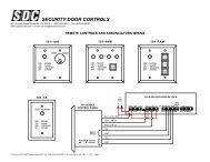
SECURITY DOOR CONTROLS<br />
801 Avenida Acaso, Camarillo, Ca. 93012 • (805) 494-0622 • Fax: (805) 494-8861<br />
www.sdcsecurity.com • E-mail: service@sdcsecurity.com<br />
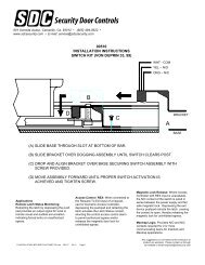
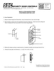
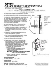
INSTALLATION INSTRUCTIONS<br />
MICRO SHEAR EMLOCKS 1561 & 1562 MAX. HOLDING FORCE 2000 LBS.<br />
REFER TO THE PROPER TEMPLATE ACCORDING TO THE TYPE OF DOOR AND FRAME APPLICATION.<br />
READ THESE INSTRUCTIONS AND STUDY THE TEMPLATE THOROUGHLY BEFORE BEGINNING THE INSTALLATION.<br />
IMPORTANT NOTES:<br />
Although electromagnetic shear locks provide the utmost in aesthetics for fail-safe applications, they are less forgiving than electric<br />
bolt locks and direct pull magnetic locks where alignment problems exist. Therefore, great care must be taken during preparation<br />
and installation of the frame, door hardware and the shear Emlock to attain proper alignment and ensure positive lock operation.<br />
Unbalanced air conditioning (stack pressure) can hinder door alignment and must be corrected to help ensure positive locking.<br />
Use only the highest quality door closer.<br />
POSITIVE CENTERING DOOR CLOSERS ONLY should be used on double acting doors to help attain consistent dead center<br />
alignment.<br />
<strong>Door</strong> latching problems must be corrected prior to installation.<br />
The maximum locking strength of the 1561/1562 Hi/Shear Emlock is 2000 lbs.<br />
INSTALLATION:<br />
1. Make sure the clearance between the door top rail and frame header is 1/8”. Make adjustments to the door as required.<br />
2. Adjust single acting door and door closer to ensure the door settles immediately and is fully closed and at rest against the<br />
stop allowing for mutes, smoke seals or weather stripping where applicable.<br />
Adjust double acting door and POSITIVE CENTERING DOOR CLOSER to ensure the door settles immediately and is fully closed<br />
and at rest in the dead center of the frame.<br />
3. Locate the vertical centerline of the Emlock and armature as close as possible to the leading door edge.<br />
CAUTION: Wood door applications require the armature back box to be located and ample distance from the door<br />
edge vertical grains, to avoid splitting from wood screws.<br />
4. Determine the horizontal centerline of the door top rail thickness. The armature centerline will be the same.<br />
Mark the door per the template.<br />
5. Before determining the frame header centerline, single acting doors must be fully closed and at rest against the stop allowing for<br />
mutes, smoke or weather stripping where applicable. Double acting doors must be fully closed and at rest in the dead center of<br />
the frame.<br />
6. Mark the frame header per the template.<br />
7. Prepare the door and frame per the template.<br />
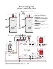
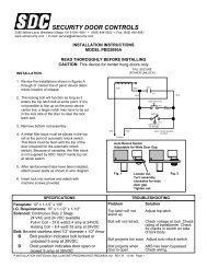
8. An auto relock time delay (built-in with 1561) is recommended for all installations to delay relocking 1 to 6 seconds after initial<br />
door closure. This will help ensure the door is fully closed and at rest to obtain optimum alignment before the Emlock is energized.<br />
Consult Figure 7A or 7B according to material supplied.<br />
With the power off, make all wire connections to a properly fused power source.<br />
P:\INSTALLATION INST\ELECTROMAGNETIC LOCKS\INST-SHEAR 61-62\INST-SHEAR 61-62.vsd REV F 01-13 Page 1<br />
Any suggestions or comments to this instruction or<br />
product are welcome. Please contact us through<br />
our website or email engineer@sdcsecurity.com
9. When installing 1562 model use Figure 7B, make the timer adjustment as required and test the TDA time delay prior to<br />
mounting in the frame. The TDA timer is field adjustable for 1 to 6 seconds and is factory set at approximately 3 seconds.<br />
turn clockwise to increase and counter clockwise to decrease the delay time.<br />
10. Install the Emlock and armature with the auto relock switch assembly towards the leading edge of the door.<br />
The 1561 timer adjustment can be made after the Emlock is installed through the small hole in the face of the magnet. Using a<br />
small flat blade screwdriver, turn clockwise to increase time, counter clockwise to decrease time.<br />
11. For proper operation, the armature must be adjusted upward as close as possible and parallel to the Emlock without interfering<br />
with opening and closing of the door. Proper operation cannot be expected with more than 1/8” clearance between the armature<br />
and the Emlock. If you find the clearance to be more than 1/8”, shim the assembly with the shims provided.<br />
12. With the door closed, turn the lock power on. Check the lateral alignment. The armature shear stops should be centered<br />
between each pair of magnet shear stops.<br />
13. If the clearance between the shear stops is sufficient, open and close the door a few times to ensure the Emlock will lock and<br />
unlock positively.<br />
14. Adjust the auto relock switch magnet to avoid early activation and help ensure positive locking on door closure. Adjust inward to<br />
delay Emlock activation. Do not adjust higher than the armature rest position.<br />
15. If the shear stops are too close or binding, double check the templating and door alignment, and make corrections as required.<br />
16. If positive locking cannot be attained due to misalignment after the previous adjustments, the armature shear stops can be<br />
reversed with the wide clearance shear stops.<br />
CAUTION: The use of armature offset shear stops may correct misalignment but should not be used when proper door<br />
latching is inhibited.<br />
17. Repeat steps 11 through 15 as necessary following shear stop replacement.<br />
18. Cycle the door and Emlock several times after the completion of installation.<br />
MODEL #<br />
LOCK DIMENSION<br />
L W D<br />
HOLDING<br />
FORCE<br />
POWER<br />
CONSUPTION<br />
12VDC 24VDC<br />
MODEL #<br />
ARMATURE DIMENSION<br />
L W D<br />
1561<br />
8" 1-1/2” 1-5/8”<br />
2000<br />
650mA<br />
350mA<br />
ITCM<br />
8-7/16" 1-1/2”<br />
7/8”<br />
1562<br />
8" 1-1/2” 1-1/4”<br />
2000<br />
650mA<br />
350mA<br />
FTCM<br />
8-7/16"<br />
1-1/2”<br />
7/8”<br />
HTCM<br />
8-7/16"<br />
1-1/2” 7/8”<br />
P:\INSTALLATION INST\ELECTROMAGNETIC LOCKS\INST-SHEAR 61-62\INST-SHEAR 61-62.vsd REV F 01-13 Page 2
FIGURE 1<br />
LEADING EDGE<br />
OF DOOR<br />
MPM<br />
MPA<br />
MIDPOINT IDENTIFICATION<br />
MPM – MIDPOINT MAGNET<br />
MPA – MIDPOINT ARMATURE<br />
THE MOST IMPORTANT ELEMENTS FOR THE PROPER<br />
INSTALLATION OF THE HI/SHEAR MAGNET ASSEMBLY<br />
ARE THAT THE MIDPOINT OF THE ARMATURE AND<br />
THE MIDPOINT OF THE MAGNET MUST LINE UP EXACTLY.<br />
ALL CENTERLINES OF THE ARMATURE MUST LINE UP<br />
WITH THE RESPECTIVE CENTERLINES OF THE MAGNET<br />
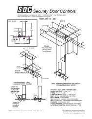
FIGURE 2<br />
13/16<br />
3/4<br />
REINFORCEMENT TAB<br />
<strong>SDC</strong> PART # 006-007-10<br />
1-5/8 1-5/8<br />
7-15/16<br />
8-7/16<br />
C L<br />
7/16<br />
7/8 1-1/2<br />
13/16<br />
MPA<br />
C L<br />
4-9/32 4-9/32<br />
4-23/32 4-23/32 13/16<br />
CAPPED TOP DOOR HOLLOW METAL DOOR TEMPLATE<br />
8 HOLES 3/16 DIA<br />
5/16 x 82 DEG CSK<br />
FOR #8-32 SCREWS<br />
FIGURE 3<br />
7/8<br />
To<br />
1-1/8<br />
C L<br />
DOOR<br />
1-5/8<br />
31/32<br />
4 HOLES #1/4-20 UNC-2B<br />
2-11/32<br />
MPA<br />
C L<br />
1-5/8<br />
1/2” DIA 2 PLCS<br />
1-3/4 3/4<br />
3/8<br />
.450<br />
1-5/8<br />
2-11/32<br />
31/32<br />
1-5/8<br />
METAL DOOR TEMPLATE 7/8" TO 1-1/8" DEPTH CHANNEL<br />
P:\INSTALLATION INST\ELECTROMAGNETIC LOCKS\INST-SHEAR 61-62\INST-SHEAR 61-62.vsd REV F 01-13 Page 3
FIGURE 4<br />
13/16<br />
METAL FRAME TEMPLATE<br />
7/16<br />
25/32<br />
7/8<br />
1-9/16<br />
C L OF<br />
MAGNET<br />
MPM 4.0"<br />
7/16 C L OF MAGNET 8 HOLES 3/16 DIA<br />
CSK 5/16 x 82 DEG<br />
REINFORCEMENT TAB<br />
8.0"<br />
1-5/8<br />
<strong>SDC</strong> PART# 006-007-10<br />
3/4<br />
13/16<br />
FOR 1561<br />
1/8 A<br />
4-7/16<br />
10-1/2<br />
4-7/16<br />
REINFORCEMENT TAB REVERSED<br />
FOR HOLLOW METAL FRAME<br />
DETAIL A<br />
16 GAUGE<br />
1/4 to 3/4<br />
SHIM IN 1/8" INCREMENTS<br />
AS REQUIRED<br />
<strong>SDC</strong> PART# 006-001-14<br />
1-3/4 7/8 7/16<br />
4 HOLES #8-32 UNF-2B<br />
1-5/8 1-5/8<br />
7-15/16<br />
3-31/32 3-31/32<br />
1-1/2<br />
MPA<br />
3-7/16 3-7/16<br />
6-7/8<br />
DOOR<br />
1/8<br />
7/8<br />
1-1/16<br />
FOR 1561<br />
METAL DOOR<br />
TEMPLATE<br />
1/4” TO 3/4”<br />
CHANNEL DEPTH<br />
FIGURE 5<br />
C L<br />
31/32<br />
1-15/16<br />
7/8<br />
1.0<br />
DOOR<br />
SHIM REQUIRED OPTIONAL<br />
<strong>SDC</strong> PART# 006-001-11<br />
1-5/8<br />
2-11/32 1-5/8<br />
2-11/32 31/32<br />
1-3/4<br />
3/8<br />
3/4 1-1/4<br />
C L<br />
MPA C L<br />
5/8 5/8<br />
SHIM, <strong>SDC</strong> PART # 006-001-11<br />
HERCULITE DOOR TEMPLATE<br />
FIGURE 6<br />
1-1/16<br />
5/32<br />
C L<br />
4X #10 x 1-1/2”<br />
WOOD SCREWS<br />
4 HOLES FOR<br />
#10 x 1-1/2”<br />
WOOD SCREWS<br />
1-5/8 1-5/8<br />
2X 1/2 DIA<br />
OPTIONAL DOOR<br />
REINFORCEMENT HOUSING<br />
<strong>SDC</strong> PART # WDRBM<br />
1-1/2<br />
7/8<br />
1/2<br />
3-17/32<br />
3-31/32<br />
4-9/32<br />
1-5/8 1-5/8<br />
3-17/32<br />
3-31/32<br />
4-9/32<br />
C L WOOD DOOR TEMPLATE<br />
P:\INSTALLATION INST\ELECTROMAGNETIC LOCKS\INST-SHEAR 61-62\INST-SHEAR 61-62.vsd REV F 01-13 Page 4
FIGURE 7<br />
Figure A<br />
LOCK<br />
Model 1561 – With built in<br />
Auto Relock Switch Auto<br />
Relock Delay Timer<br />
red/blk<br />
wht/blk<br />
ACCESS<br />
CONTROL<br />
+<br />
-<br />
To Fused 12V or 24V<br />
DC Power Source<br />
DPS OPTION<br />
YEL = N/O<br />
GRY = COM<br />
ORG = N/C<br />
BAS OPTION<br />
WHT = N/O<br />
BLK = COM<br />
RED = N/C<br />
Figure B<br />
red/blk<br />
ACCESS<br />
CONTROL<br />
LOCK<br />
TDA<br />
Model 1562 – With built in<br />
Auto Relock Switch and<br />
Auxiliary Auto Relock Delay<br />
Timer Board<br />
wht/blk<br />
- +<br />
To Fused 12V or 24V<br />
DC Power Source<br />
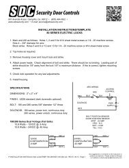
FIGURE 8<br />
Please note the drawing in<br />
Fig. 1. It show two different<br />
alignments off center of the<br />
shear tab.<br />
.343<br />
wide<br />
For normal single acting and<br />
double acting door alignment<br />
see Fig. 2.<br />
.312<br />
Fig. 2<br />
006-001-04A<br />
For slightly warped single<br />
acting doors see Fig. 4.<br />
This also works well for quick<br />
release, when switch bars<br />
are used.<br />
Fig. 1<br />
006-001-04A<br />
Fig. 4<br />
006-001-04A<br />
The offset shear tab cannot<br />
be used on shear locks with<br />
bond sensors.<br />
wide<br />
Fig. 3<br />
006-001-04A<br />
Offset shear tabs<br />
ARMATURE TOP VIEW<br />
ARMATURE SHEAR TAB<br />
INSTALLATION<br />
P:\INSTALLATION INST\ELECTROMAGNETIC LOCKS\INST-SHEAR 61-62\INST-SHEAR 61-62.vsd REV F 01-13 Page 5
MAINTENANCE INSTRUCTIONS<br />
The electromagnet and the armature should be handled carefully. Any damage to<br />
the surface such as paint, burrs, dirt and rust may hinder bonding of the surface<br />
and reduce holding power.<br />
IF THE SURFACE PLATING BECOMES DAMAGED<br />
1. Do not touch lock face with your hands.<br />
2. Use a soft clean dry cloth or abrasive cloth (i.e., Scotch-Brite by 3M) to clean the<br />
lock face. Do not use sand paper.<br />
3. A rust inhibitor, such as M1 manufactured by Starret, or LPS3 manufactured by<br />
LPS Laboratories (available in most hardware stores) can then be applied to the<br />
lock face.<br />
4. Apply a coat of rust inhibitor to the armature face also.<br />
P:\INSTALLATION INST\ELECTROMAGNETIC LOCKS\INST-SHEAR 61-62\INST-SHEAR 61-62.vsd REV F 01-13 Page 6