Installation - SDC Security Door Controls
Installation - SDC Security Door Controls
Installation - SDC Security Door Controls

You also want an ePaper? Increase the reach of your titles
YUMPU automatically turns print PDFs into web optimized ePapers that Google loves.
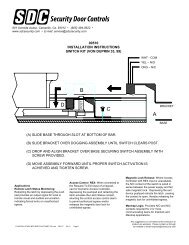
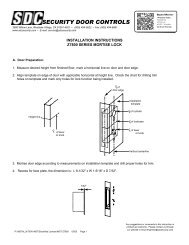
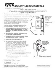
801 Avenida Acaso, Camarillo, Ca. 93012• (805) 494-0622 • www.sdcsecurity.comE-mail: service@sdcsecurity.comINSTALLATION INSTRUCTIONS30-4 ELECTRIC STRIKEThe following instructions cover all models of the 30-4 Electric Strike.INSTALLATION:1. For proper installation of the 30-4 Electric Strike, refer to the appropriate templatedrawing. The centerline of the latch bolt must be aligned with the centerline of the strike.NOTE: Not compatible with <strong>SDC</strong> 6000 Series Rim Devices. Check manufacturers exitdevice template for compatibility.2. Prior to installation, make the necessary wire connections per the appropriate wiring diagram.3. Proper operating voltage must be supplied to the strike if it is to function correctly. Voltageat the strike must be within +/-10% of the required voltage listed on the strike label.4. To install the strike into the frame opening:A) Position the wiring either down, up or toward the back of the hollow metal frame,making sure that it stays completely out of the way of the strike to avoid being pinchedduring installation.B) Mount the strike using the screws supplied.5. After installation, check the horizontal alignment. Be certain that the centerline of the latchbolt is aligned with the centerline of the strike.6. In case of misalignment, there is a 3/16" horizontal adjustment between the strikemechanism and the face plate. To adjust:A) Remove mounting screws.B) Remove strike from frame.C) Loosen the two (2) #12-24 x 3/8” hex washer head cap screws.D) Reposition strike and re-tighten cap screws.OPERATION:The <strong>SDC</strong> 30-4 Electric Strike is a solenoid operated device.1. NON-FAIL SAFEWhen power is applied the solenoid pulls the locking cam into the unlocked positionallowing the door to be opened. If power fails the strike will remain locked.NOTE: Non-fail safe strikes for use in fire rated doors can only be operated by momentarycontact switching (energized only when the push button is held depressed) and can notbe held in the unlocked position.2. FAIL SAFE:When the power is applied the solenoid pushes the locking cam into the locked positionand the door can not be opened. If power fails the strike will unlock.OPERATION NOTE: This product may be provided fail safe or non-fail safe. Fail safe versionsallow exit in the event of a power failure. Fail secure version do not.Consult with the local authority having jurisdiction concerning theinstallation of this type of product and whether listed panic hardware isrequired to allow emergency exit from the secured area.P:\INSTALLATION INST\ELECTRIC STRIKES\INST-30 Series\INST-30-4.vsd Rev - 12/10 Page 1
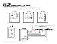
INSTALLATION INSTRUCTIONS 30-4 ELECTRIC STRIKEOPTIONAL FEATURES;1. LBM SWITCH (Latch Bolt Monitor) – A switch operated by the switch tripper that signalswhether or not the latch bolt is extended into the strike.2. LCM SWITCH (Locking Cam Monitor) – A switch operated by the roll pin on the locking camthat monitors the position of the locking cam and signals that the strike is either locked orunlocked.3. LCBM SWITCH (Locking Cam and Latch Bolt Monitor) – A switch operated by the LCMswitch tripper and the LBM switch tripper that signals that the strike is locked and thelatch bolt is engaged.4. LCBMA SWITCH (Locking Cam and Latch Bolt Monitor, wired separately) – This is the sameas the LCBM with an additional switch operated by the LBM switch tripper.5. KEEPERS – There is a standard type for each model 300 strike. Optional keepers areavailable for some models.6. SOLENOID VOLTAGE – 24VDC is standard. Optional voltages available are: 12 or 115VDC,6, 12, 24, 48 or 115VAC. NOTE: UL requires that a junction box be use with 48 and 120 voltstrikes if they are not installed in a back box.7. SILENT OPERATION (SO) – Silent operation is recommended for AC non-fail safe strikesthat are to be energized for extended periods of time. All silent operation strikes are operatedby DC solenoids. When control power source is AC, the strike is supplied with an externallyattached bridge rectifier.8. FAIL SAFE – The strike is locked when energized. This feature should be used forapplications that require automatic unlocking in case of power failure. All fail safe strikes areoperated by DC solenoids and are silent operation.CAUTION: Fail safe is not permitted with the UL Fire <strong>Door</strong> Accessory label.9. MOUNTING TAB – The mounting tab is designed to be used with the 30 series electricstrikes when mounting in metal frames.10. ASTRAGAL - A lock guard designed to prevent tampering with the strike keeper and thelatch bolt.P:\INSTALLATION INST\ELECTRIC STRIKE\INST-30-4.vsd Rev - 01/11 Page 2
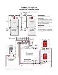
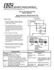
30-4 SERIES ELECTRIC STRIKE WIRING DIAGRAMSAttachment of New RectifierDC solenoidYellowYellowBridgeRectifierRating:2 Amps at ANYSolenoid Voltage(Required when supplying AC powerto a unit with a DC solenoid)-Black/YellowTracerBlack/YellowBrownBrownY*TerminalStripAttachment of Old RectifierDC solenoidRed YellowBridgeRectifierRating:2 Amps at ANYSolenoid Voltage(Required when supplying AC powerto a unit with a DC solenoid)Black/YellowTracerBlackYellowYellowY*TerminalStripSolenoidLock Cam/BoltMonitor Switch(Long Arm)N/ON/CDotted Lines RepresentField wires by othersControlPower+ - GNDIndicationPowerTypical ControlSchematic forReference only30-4 Series LCBMWiring DiagramCBlackRedBlueYellow*9 3 6 1 4+ - R B Y*PushButtonRGN/CN/OTerminalStripUnlocked When EnergizedSolenoidLock Cam/BoltMonitor SwitchN/O(Long Arm)N/CBROWN7Auxiliary ORANGE5SwitchN/O(LBM)PURPLE N/C8Dotted Lines RepresentField wires by othersControlPower+ - GND30-4 Series LCBMAWiring DiagramIndicationPowerTypical ControlSchematic forReference onlyCCBlackRedBlueYellow*9 3 6 1 4+ - R B Y*PushButtonRGN/CN/OTerminalStripUnlocked When EnergizedElectrical Ratings forVOLTAGEALL 30-4ACDCElectric Strike Solenoids 12 24 120 6 12 24 48 120Resistance in OHMS +/- 10% 6.2 23.5 500 6.2 23.5 96.0 380 1200Watts Seated 5.4 5.8 6.3 5.8 6.1 6.0 6.1 6.3Amps Seated .45 .24 .06 .97 .51 .25 .13 .06Amps Inrush 1.33 .69 .16 N/A N/A N/A N/A N/ANotice:Wiring subject to change withoutprior notice. Not responsible forcontrols furnished by others.Push Button Switch ConditionsN/C N/CLockUnlockN/O N/OP:\INSTALLATION INST\ELECTRIC STRIKE\INST-30-4.vsd Rev - 01/11 Page 3
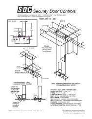
30-4 ELECTRIC STRIKE WIRING DIAGRAMS30-4 LBM wiring diagram30-4 LCM wiring diagramSolenoidLatch BoltMonitor SwitchN/ON/CDotted Lines RepresentField wires by othersControlPower+ - GND*BrownBLKIndicationPowerTypical ControlSchematic forReference onlyCOrangePurpleYellow*7 5 8 1 4+ - R B Y*PushButtonRGN/CN/OUnlocked When EnergizedTerminalStripLatch BoltMonitor SwitchOptional 9-Pin Field Wiring Conn.GRY orBRNStrike Wires7 5 8 9 3 6 2 1*7 5 8 9 3 6 2 1 4ORGPURREDAux ContactsBLUYELYELWHTSolenoidNOTES:1) = Wires color code6 thru 120 VDC Yellow/Black Tracer12 & 24 VAC-Grey120 VAC-White2) Unused wires to be individually isolated with a wire nut or equal.3) Numbered field connections refer to pin location in field receptacle.N/ON/CDotted Lines RepresentField wires by othersControlPower+ - GNDTypical ControlSchematic forReference onlyPin #2Not UsedFieldConnectorBlackIndicationPowerCRedBlueYellow*9 3 6 1 4+ - R B Y*PushButtonRGN/CN/OUnlocked When EnergizedTerminalStripControlPower+ - GNDFail Safe <strong>Controls</strong>IndicationPowerTypical ControlSchematic forReference only75AuxiliaryContacts8FieldReceptacle+ - R B Y*GreyOrangePurplePushButtonRGN/CN/OTerminalStripLocked When Energized(Fail Safe) all 300 StrikesOptional DBS Switch(not available with LCBMA)<strong>Door</strong> shown closed and locked.Dead Bolt Extended into Face Plate1236 5 49 8 7PinLocation<strong>Installation</strong> Must Be Properly GroundedPer National Electrical Code Article 250P:\INSTALLATION INST\ELECTRIC STRIKE\INST-30-4.vsd Rev - 01/11 Page 4
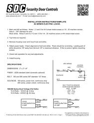
MAINTENANCE AND LUBRICATION INSTRUCTIONSUnder normal usage the 30-4 Electric Strike should be cleaned and lubricated once a year to maintain it’s reliability.In applications with high usage or dirty conditions more frequent service may be necessary. Lubrication points are identified inthe illustration. When servicing the 30-4 Electric Strike, inspect the internal parts for excess wear or breakage and lightlylubricate per instructions below. Lubricate with lightening grease available from <strong>SDC</strong>. Never lubricate any strike with oil!Such lubrication collects dirt and forms an abrasive and sticky compound that may affect the function of the strike.TO INSPECT AND LUBRICATE THE STRIKE;1. Remove the strike from the face plate (held on by (2) #12-24 X 3/8” Hex Washer Head Cap SCREWS).2. Remove the upper cover held on by (2) #4-40 X 3/16” PHMS. Removal of the upper cover should be done slowly becausethe locking cam spring may snap out of place. Also, care should be taken to insure that the locking cam spacer andlocking lever spacer are not lost.3. Remove the cam spring spacer, cam spring and locking lever spacer.4. Loosen the (2) #6-32 X 1/8” SSSC holding the solenoid, then remove the solenoid and locking cam.5. Remove the locking lever spring and locking lever. In some versions of the strike, there is a recess in the locking lever andthe case for this spring. In cases with the recess, the locking lever spring must be compressed into the lever before it canbe removed.6. Lubricate the area in the case where the locking lever and locking cam rest (be careful not to get any lubricant on thesolenoid or switches). Lubricate the cam pin and lever pin.7. Check the locking angle of the keeper and locking lever for wear. Replace the keeper and/or lever if worn (if the keeperis disassembled for replacement or adding of a switch, lubricate the keeper pin).8. Reinstall the locking lever and a new locking lever spring. CAUTION: Make sure the locking lever is placed back into therecesses of the locking lever and the case.9. Check the solenoid, plunger and plunger guide for excess wear, dirt, grime or oil. If present, wipe clean.FAIL SAFE: Remove the retaining ring for inspection of the plunger guide. Reassemble the solenoid and plunger witha new retaining ring.NON-FAIL SAFE: Lubricate the bottom edge of the locking cam (contact point of the solenoid plunger).10. NON-FAIL SAFE: Lubricate the slot in the locking camFAIL SAFE: Lubricate the bottom edge of the locking cam (contact point of the solenoid plunger).Lightening greasehubs where theycontact keeperLightening greasekeeper pinbefore assemblyLightening greasepins and bottomof caseLightening greasecam slot and bothcam surfacesbetween plungerLightening greasesides of keeperbefore assemblyLightening greasebottom of camand plunger pinRear view shownwith LCBM switchFront ViewNon Fail SafeShown UnlockedP:\INSTALLATION INST\ELECTRIC STRIKE\INST-30-4.vsd Rev - 01/11 Page 5Front viewFail SafeShown Locked
MAINTENANCE AND LUBRICATION INSTRUCTIONS11. <strong>Installation</strong> and positioning of the solenoid.NON-FAIL SAFE1) Install the solenoid and locking cam assembly2) Install the locking cam spring (with the long leg of the spring on the locking cam and the short leg in thegroove on the case).3) Before tightening the set screws, energize the solenoid and check the position of the locking cam and locking lever.4) Adjust the solenoid position to where the locking lever will clear the locking cam and tighten set screws.FAIL SAFE1) Install the solenoid and locking cam.2) Install the locking cam spring (with the long leg of the spring on the locking cam and the short leg in thegroove on the case).3) Before tightening the set screws, energize the solenoid and check the position of the locking cam.4) Adjust the position of the solenoid to where it pushes the locking cam into the fully locked position (be careful not toposition the solenoid too high or the solenoid plunger will not seat).5) De-energize and make sure the locking cam falls to a level to be unlocked. Tighten set screws.12. Check all screws, tighten if necessary. CAUTION: Do not over tighten the switch screws. Over tightening could damagethe switch.13. Reinstall the cam spring spacer and the locking lever spacer.14. Reinstall the upper cover.15. Reassemble the strike to the face plate.Locked PositionLoosen set screwsto position solenoid.Tighten after positionis set.Unlocked PositionFront ViewFail SafeShown LockedFront ViewNon Fail SafeShown UnlockedP:\INSTALLATION INST\ELECTRIC STRIKE\INST-30-4.vsd Rev - 01/11 Page 6