Installation - SDC Security Door Controls
Installation - SDC Security Door Controls
Installation - SDC Security Door Controls

You also want an ePaper? Increase the reach of your titles
YUMPU automatically turns print PDFs into web optimized ePapers that Google loves.
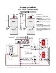
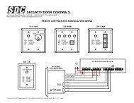
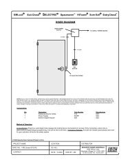
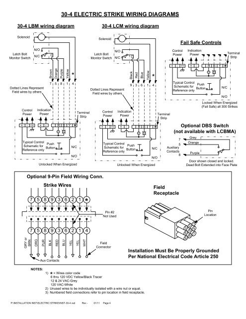
30-4 ELECTRIC STRIKE WIRING DIAGRAMS30-4 LBM wiring diagram30-4 LCM wiring diagramSolenoidLatch BoltMonitor SwitchN/ON/CDotted Lines RepresentField wires by othersControlPower+ - GND*BrownBLKIndicationPowerTypical ControlSchematic forReference onlyCOrangePurpleYellow*7 5 8 1 4+ - R B Y*PushButtonRGN/CN/OUnlocked When EnergizedTerminalStripLatch BoltMonitor SwitchOptional 9-Pin Field Wiring Conn.GRY orBRNStrike Wires7 5 8 9 3 6 2 1*7 5 8 9 3 6 2 1 4ORGPURREDAux ContactsBLUYELYELWHTSolenoidNOTES:1) = Wires color code6 thru 120 VDC Yellow/Black Tracer12 & 24 VAC-Grey120 VAC-White2) Unused wires to be individually isolated with a wire nut or equal.3) Numbered field connections refer to pin location in field receptacle.N/ON/CDotted Lines RepresentField wires by othersControlPower+ - GNDTypical ControlSchematic forReference onlyPin #2Not UsedFieldConnectorBlackIndicationPowerCRedBlueYellow*9 3 6 1 4+ - R B Y*PushButtonRGN/CN/OUnlocked When EnergizedTerminalStripControlPower+ - GNDFail Safe <strong>Controls</strong>IndicationPowerTypical ControlSchematic forReference only75AuxiliaryContacts8FieldReceptacle+ - R B Y*GreyOrangePurplePushButtonRGN/CN/OTerminalStripLocked When Energized(Fail Safe) all 300 StrikesOptional DBS Switch(not available with LCBMA)<strong>Door</strong> shown closed and locked.Dead Bolt Extended into Face Plate1236 5 49 8 7PinLocation<strong>Installation</strong> Must Be Properly GroundedPer National Electrical Code Article 250P:\INSTALLATION INST\ELECTRIC STRIKE\INST-30-4.vsd Rev - 01/11 Page 4