Installation - SDC Security Door Controls
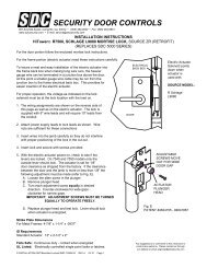
Installation - SDC Security Door Controls
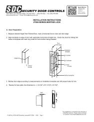
Installation - SDC Security Door Controls

Create successful ePaper yourself
Turn your PDF publications into a flip-book with our unique Google optimized e-Paper software.
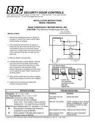
MAINTENANCE AND LUBRICATION INSTRUCTIONSUnder normal usage the 30-4 Electric Strike should be cleaned and lubricated once a year to maintain it’s reliability.In applications with high usage or dirty conditions more frequent service may be necessary. Lubrication points are identified inthe illustration. When servicing the 30-4 Electric Strike, inspect the internal parts for excess wear or breakage and lightlylubricate per instructions below. Lubricate with lightening grease available from <strong>SDC</strong>. Never lubricate any strike with oil!Such lubrication collects dirt and forms an abrasive and sticky compound that may affect the function of the strike.TO INSPECT AND LUBRICATE THE STRIKE;1. Remove the strike from the face plate (held on by (2) #12-24 X 3/8” Hex Washer Head Cap SCREWS).2. Remove the upper cover held on by (2) #4-40 X 3/16” PHMS. Removal of the upper cover should be done slowly becausethe locking cam spring may snap out of place. Also, care should be taken to insure that the locking cam spacer andlocking lever spacer are not lost.3. Remove the cam spring spacer, cam spring and locking lever spacer.4. Loosen the (2) #6-32 X 1/8” SSSC holding the solenoid, then remove the solenoid and locking cam.5. Remove the locking lever spring and locking lever. In some versions of the strike, there is a recess in the locking lever andthe case for this spring. In cases with the recess, the locking lever spring must be compressed into the lever before it canbe removed.6. Lubricate the area in the case where the locking lever and locking cam rest (be careful not to get any lubricant on thesolenoid or switches). Lubricate the cam pin and lever pin.7. Check the locking angle of the keeper and locking lever for wear. Replace the keeper and/or lever if worn (if the keeperis disassembled for replacement or adding of a switch, lubricate the keeper pin).8. Reinstall the locking lever and a new locking lever spring. CAUTION: Make sure the locking lever is placed back into therecesses of the locking lever and the case.9. Check the solenoid, plunger and plunger guide for excess wear, dirt, grime or oil. If present, wipe clean.FAIL SAFE: Remove the retaining ring for inspection of the plunger guide. Reassemble the solenoid and plunger witha new retaining ring.NON-FAIL SAFE: Lubricate the bottom edge of the locking cam (contact point of the solenoid plunger).10. NON-FAIL SAFE: Lubricate the slot in the locking camFAIL SAFE: Lubricate the bottom edge of the locking cam (contact point of the solenoid plunger).Lightening greasehubs where theycontact keeperLightening greasekeeper pinbefore assemblyLightening greasepins and bottomof caseLightening greasecam slot and bothcam surfacesbetween plungerLightening greasesides of keeperbefore assemblyLightening greasebottom of camand plunger pinRear view shownwith LCBM switchFront ViewNon Fail SafeShown UnlockedP:\INSTALLATION INST\ELECTRIC STRIKE\INST-30-4.vsd Rev - 01/11 Page 5Front viewFail SafeShown Locked