Create successful ePaper yourself
Turn your PDF publications into a flip-book with our unique Google optimized e-Paper software.
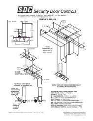
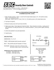
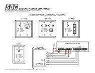
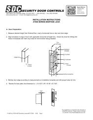
SECURITY DOOR CONTROLS801 Avenida Acaso, Camarillo, Ca. 93012 • (805) 494-0622 • Fax: (805) 494-8861www.sdcsecurity.com • E-mail: service@sdcsecurity.comINSTALLATION INSTRUCTIONSHiTower ® R7500, SCHLAGE L9080 MORTISE LOCK, SOURCE ZR (RETROFIT)(REPLACES <strong>SDC</strong> 5000 SERIES)For the door portion follow the enclosed mortise lock instructions.For the frame portion (electric actuator) read these instructions carefully.To insure a neat and easy installation of the electric actuator intothe frame back box when making long wire runs, the heaviergauge wire can be terminated in a junction box above the door.At this point a smaller gauge wire cable may be run from thejunction box to the frame electrical back box. This provides foreasier insertion of the electric actuator.For proper operation, the voltage as indicated on the locksolenoid must be at the lock location with the load on.1. The wiring assignments are shown on the reverse side ofthis page as well as on the electric actuator. The lock issupplied with 6" wire leads and will require 10" leads fromthe conduit.DOORELECTRICALBACK BOXElectric ActuatorSolenoid pointsdown whenactuator isused with:SOURCE MODEL:R SchlageL90802. Attach power supply leads to lock leads as shown. Wirenuts are sufficient for these connectionsFRAME3. Insert wires into the jamb carefully so they do not interferewith proper positioning of the lock in the cut-out.4. Insert lock and secure with screws provided.5. With the electric actuator power on, check to see if thelevers are locked. On 7540 and 7550 models only theoutside lever should lock. The actuator is set for 1/8”door clearance as shipped from the factory. If the clearancebetween the door and the jamb is more or less than 1/8” thefollowing adjustment must be made (refer to Fig. E).A. Loosen the allen screw in the plunger.B. Remove plunger head.C. Turn each adjustment screw equally in desireddirection. Counter-clockwise for wide gaps -clockwise for narrow gaps.IMPORTANT: ADJUSTMENT SCREWS MUST BE TURNEDEQUALLY TO OPERATE FREELY.D. Replace plunger head and test lock. Lever should lockwhen actuator is energized.ADJUSTABLESCREWS MOVEOUT FOR WIDEDOOR GAPACTUATORPLUNGERHEADFig. EPATENT #4634155 - #4641867Strike Plate DimensionsFor Metal Frames: 4-7/8” x 1-1/4” x .0937"ID RequirementsStandard Actuator: 12" x 2-1/2” x 2"Fails Safe: Continuous duty – locked when energizedUL Listed: Electrically controlled single point locks or latches.P:\INSTALLATION INST\Electrified Lockset\INST-7500HI-R REV A 02-10 Page 1Any suggestions or comments to this instruction orproduct are welcome. Please contact us throughour website or email engineer@sdcsecurity.com
+-REDWHITEVoltage and current rating stamped on solenoidGround screw is provided on 115VAC locksCN/CN/OBLU/BLK Common BLU/BLK CommonORG/BLK Indicates door open ORG Indicates door unlockedYEL/BLK Indicates door latch YEL Indicates door secure*LSOptional 9A Latch Position SensorSPDT 5 Amps @ 125VACWiring assignments for the optional SC-10 cable with socket connectors are the sameVOLTAGE 24VDC 24VAC 115VACRESISTANCE INOHMS 5%47.6 13.6 .20AMPS+ -.45 .5 .20FUNCTIONSLLSOptional 69A Secure SensorSPDT 5 Amps @ 125VACImportant Note: Because of design,field OHM tests of AC solenoids mayproduce erratic readings and cannotbe used to determine the solenoidscondition.7510 Mortise lock is unlocked by remote switch.Suggested: storerooms, records, utility,tool cribs, man trap7520 Mortise lock is unlocked by remote switchor outside keySuggested: storerooms, records, utility,tool cribs, man trap7530 Mortise lock is unlocked by remote switch, orby a key from either side.Suggested: communicating locks, man trap7540 Mortise lock is unlocked by remote switch, orby rotating the inside lever which retracts themortise latch bolt and the auxiliary latchSuggested: stair tower doors, control centersvaults, man trap7550 Mortise lock is unlocked by remote switch,or by an outside key or by rotating the insideleverSuggested: stair tower doors, classrooms,laboratories, offices, man trapTROUBLE SHOOTING HiTOWER ® 7500 SERIESThe 7500 Series is a (PL) Electric Power to Lock Unit which is failsafe in that it unlocks when power is removed. The mostcommonly used function is the 7540 and 7550 models which are locked when energized on the outside and free on theinside for egress. Models 7510, 7520 and 7530 lock on both sides when energized.PROBLEM CAUSE SOLUTIONS(1) Power on controller plungerdoes not throw(2) Latch bolt throws only part wayLock chatters or buzzes.(3) Inside lever is locked, outside is free(4) Latch position switch does not signalproperly.1A Insufficient voltage1B Binding caused by uneven plungeradjustment1C Electric portion wired wrong2A <strong>Door</strong> alignment does not permit latchbolt to enter strike.3A Incorrect handing4A 9A adjustment is off.1A Check voltage with a meter at the lockfarthest from source with all locks energized.Meter should indicated the same voltagestamped on the solenoid body. If voltage islow either too small of a wire gauge wasused or there is too great of a load on the line.1B Adjust plunger evenly.1C Review wiring diagram on side of lock &instruction sheet.2A Proper alignment must be achieved bycorrectly hanging the door in a properlyinstalled frame, modifying the lock andstrike will not remedy the problem.Modification will only void UL listing andwarranty.3A Remove Mortise lock & reverse hand.4A Adjust sensor. See Step 1 of instructionsP:\INSTALLATION INST\Electrified Lockset\INST-7500HI-R REV A 02-10 Page 2