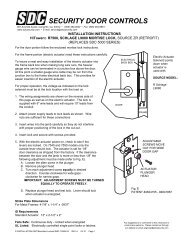
Installation - SDC Security Door Controls
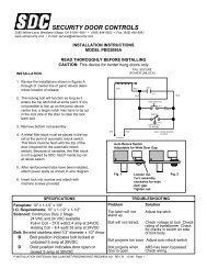
Installation - SDC Security Door Controls
Installation - SDC Security Door Controls

You also want an ePaper? Increase the reach of your titles
YUMPU automatically turns print PDFs into web optimized ePapers that Google loves.
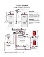
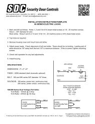
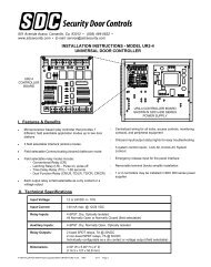
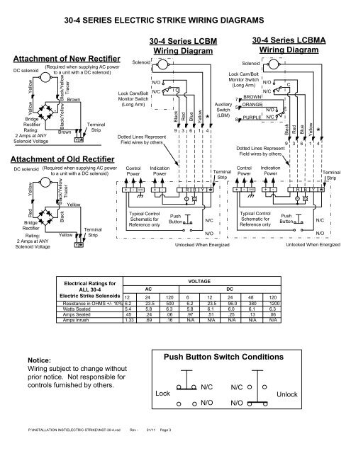
30-4 SERIES ELECTRIC STRIKE WIRING DIAGRAMSAttachment of New RectifierDC solenoidYellowYellowBridgeRectifierRating:2 Amps at ANYSolenoid Voltage(Required when supplying AC powerto a unit with a DC solenoid)-Black/YellowTracerBlack/YellowBrownBrownY*TerminalStripAttachment of Old RectifierDC solenoidRed YellowBridgeRectifierRating:2 Amps at ANYSolenoid Voltage(Required when supplying AC powerto a unit with a DC solenoid)Black/YellowTracerBlackYellowYellowY*TerminalStripSolenoidLock Cam/BoltMonitor Switch(Long Arm)N/ON/CDotted Lines RepresentField wires by othersControlPower+ - GNDIndicationPowerTypical ControlSchematic forReference only30-4 Series LCBMWiring DiagramCBlackRedBlueYellow*9 3 6 1 4+ - R B Y*PushButtonRGN/CN/OTerminalStripUnlocked When EnergizedSolenoidLock Cam/BoltMonitor SwitchN/O(Long Arm)N/CBROWN7Auxiliary ORANGE5SwitchN/O(LBM)PURPLE N/C8Dotted Lines RepresentField wires by othersControlPower+ - GND30-4 Series LCBMAWiring DiagramIndicationPowerTypical ControlSchematic forReference onlyCCBlackRedBlueYellow*9 3 6 1 4+ - R B Y*PushButtonRGN/CN/OTerminalStripUnlocked When EnergizedElectrical Ratings forVOLTAGEALL 30-4ACDCElectric Strike Solenoids 12 24 120 6 12 24 48 120Resistance in OHMS +/- 10% 6.2 23.5 500 6.2 23.5 96.0 380 1200Watts Seated 5.4 5.8 6.3 5.8 6.1 6.0 6.1 6.3Amps Seated .45 .24 .06 .97 .51 .25 .13 .06Amps Inrush 1.33 .69 .16 N/A N/A N/A N/A N/ANotice:Wiring subject to change withoutprior notice. Not responsible forcontrols furnished by others.Push Button Switch ConditionsN/C N/CLockUnlockN/O N/OP:\INSTALLATION INST\ELECTRIC STRIKE\INST-30-4.vsd Rev - 01/11 Page 3