SW7 Inlets - City of Fort Wayne
SW7 Inlets - City of Fort Wayne
SW7 Inlets - City of Fort Wayne

Create successful ePaper yourself
Turn your PDF publications into a flip-book with our unique Google optimized e-Paper software.
<strong>City</strong> Utilities Design Standards Manual Chapter 7<br />
Stormwater Design<br />
<strong>Inlets</strong><br />
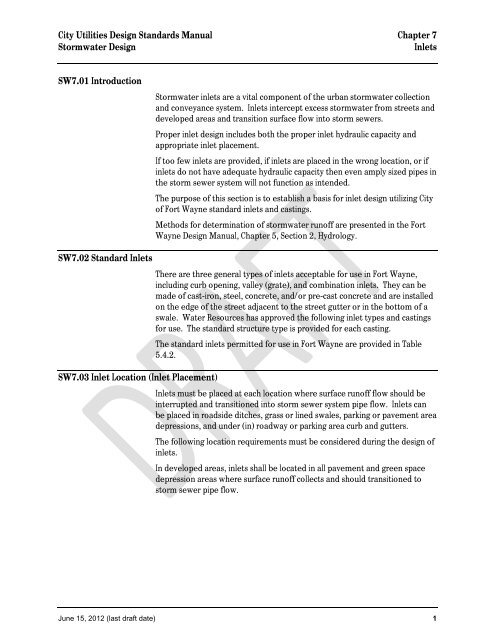
<strong>SW7</strong>.01 Introduction<br />
Stormwater inlets are a vital component <strong>of</strong> the urban stormwater collection<br />
and conveyance system. <strong>Inlets</strong> intercept excess stormwater from streets and<br />
developed areas and transition surface flow into storm sewers.<br />
Proper inlet design includes both the proper inlet hydraulic capacity and<br />
appropriate inlet placement.<br />
If too few inlets are provided, if inlets are placed in the wrong location, or if<br />
inlets do not have adequate hydraulic capacity then even amply sized pipes in<br />
the storm sewer system will not function as intended.<br />
The purpose <strong>of</strong> this section is to establish a basis for inlet design utilizing <strong>City</strong><br />
<strong>of</strong> <strong>Fort</strong> <strong>Wayne</strong> standard inlets and castings.<br />
Methods for determination <strong>of</strong> stormwater run<strong>of</strong>f are presented in the <strong>Fort</strong><br />
<strong>Wayne</strong> Design Manual, Chapter 5, Section 2, Hydrology.<br />
<strong>SW7</strong>.02 Standard <strong>Inlets</strong><br />
<strong>SW7</strong>.03 Inlet Location (Inlet Placement)<br />
There are three general types <strong>of</strong> inlets acceptable for use in <strong>Fort</strong> <strong>Wayne</strong>,<br />
including curb opening, valley (grate), and combination inlets. They can be<br />
made <strong>of</strong> cast-iron, steel, concrete, and/or pre-cast concrete and are installed<br />
on the edge <strong>of</strong> the street adjacent to the street gutter or in the bottom <strong>of</strong> a<br />
swale. Water Resources has approved the following inlet types and castings<br />
for use. The standard structure type is provided for each casting.<br />
The standard inlets permitted for use in <strong>Fort</strong> <strong>Wayne</strong> are provided in Table<br />
5.4.2.<br />
<strong>Inlets</strong> must be placed at each location where surface run<strong>of</strong>f flow should be<br />
interrupted and transitioned into storm sewer system pipe flow. <strong>Inlets</strong> can<br />
be placed in roadside ditches, grass or lined swales, parking or pavement area<br />
depressions, and under (in) roadway or parking area curb and gutters.<br />
The following location requirements must be considered during the design <strong>of</strong><br />
inlets.<br />
In developed areas, inlets shall be located in all pavement and green space<br />
depression areas where surface run<strong>of</strong>f collects and should transitioned to<br />
storm sewer pipe flow.<br />
June 15, 2012 (last draft date) 1
<strong>City</strong> Utilities Design Standards Manual Chapter 7<br />
Stormwater Design<br />
<strong>Inlets</strong><br />
TABLE 5.4.2 STANDARD INLETS<br />
APPLICABLE<br />
SETTING<br />
INLET TYPE<br />
DRAWING<br />
NO. CASTING AutoCAD File Name<br />
30" x 30" Beehive Grate<br />
Neenah R-4215 with grate C C8-1<br />
East Jordan 6610 with grate O C8-2<br />
2'x2' Curb and Gutter Casting<br />
Neenah R-3010 with grate A, R, or S C10-1, C10-3, C10-5<br />
Swale or Channel 30" Round Inlet East Jordan 7010ZM1T1 with grate M1, M5, or M3 C10-2, C10-4, C10-6<br />
Green space Precast 30" Round Inlet STR 26 2'x2' Alley Casting<br />
Pavement Field Created 30" Round Inlet STR 27 Neenah R-3036-B with grate S C9-1<br />
East Jordan 5100ZM1 with grate M1 5105 C9-2<br />
Neenah R-3036-B or East Jordan 5105 C-11<br />
33" Round Curb & Gutter Casting<br />
East Jordan 7020Z with grate M1 or M2 C12-1, C12-2<br />
Neenah R-3159 with grate S C12-3<br />
33" Round Inlet 33" Round Curb & Gutter Casting<br />
Swale or Channel Precast 33" Round Inlet STR 28 East Jordan 7020Z with grate M1 or M2 C12-1, C12-2<br />
Field Created 33" Round Inlet STR 29 Neenah R-3159 with grate S C12-3<br />
24" Beehive Casting<br />
Swale or Channel Neenah R-1772 with grate R-4351-D C7-1<br />
Green space 24" Inlet STR 30 East Jordan 1022Z1 with grate 6509-0 C10<br />
Pavement<br />
24" Storm Manhole Casting<br />
Neenah R-2502 with grate D C6-1<br />
East Jordan 1022Z1 with grate M1 C6-1<br />
2'x2' Curb and Gutter Grate<br />
Neenah-3010 or East Jordan 7010 C-12<br />
2'x2' Curb and Gutter Casting<br />
Neenah R-3010 with grate A, R, or S C10-1, C10-3, C10-5<br />
Curb 2' x 2' Inlet STR 31 East Jordan 7010ZM1T1 with grate M1, M5, or M3 C10-2, C10-4, C10-6<br />
Pavement<br />
2'x2' Alley Casting<br />
Neenah R-3036-B with grate S C9-1<br />
East Jordan 5100ZM1 with grate M1 5105 C9-2<br />
Neenah R-3036-B or East Jordan 5105 C-11<br />
2'x3' Curb and Gutter Casting<br />
Curb 2' x 3' Inlet STR 32 Neenah R-3067 with grate C or R C11-1, C11-3<br />
East Jordan 7030Z1 with grate M2, M3, or M5 C11-2, C11-4, C11-5<br />
Neenah R-3067 or East Jordan 7030 M5<br />
C13<br />
30" x 30" Beehive Grate<br />
Neenah R-4215-C<br />
C14<br />
Swale or Channel 30" x 30" Inlet STR 33 East Jordan 6610 C14<br />
Neenah R-4215 with grate C C8-1<br />
East Jordan 6610 with grate O C8-2<br />
24" Beehive Casting<br />
Neenah R-1772 with grate R-4351-D C7-1<br />
East Jordan 1022Z1 with grate 6509-0<br />
C10<br />
24" Storm Manhole Casting<br />
Neenah R-2502 with grate D C6-1<br />
East Jordan 1022Z1 with grate M1 C6-1<br />
30" x 30" Beehive Grate<br />
Neenah R-4215 with grate C C8-1<br />
Swale or Channel East Jordan 6610 with grate O C8-2<br />
Green space Standard 48" Manhole STR1, STR1a2'x2' Curb and Gutter Casting<br />
Pavement Neenah R-3010 with grate A, R, or S C10-1, C10-3, C10-5<br />
East Jordan 7010ZM1T1 with grate M1, M5, or M3 C10-2, C10-4, C10-6<br />
2'x2' Alley Casting<br />
Neenah R-3036-B with grate S C9-1<br />
East Jordan 5100ZM1 with grate M1 5105 C9-2<br />
Neenah R-3036-B or East Jordan 5105 C-11<br />
33" Round Curb & Gutter Casting<br />
East Jordan 7020Z with grate M1 or M2 C12-1, C12-2<br />
Neenah R-3159 with grate S C12-3<br />
Swale or Channel Trash Rack<br />
Pavement<br />
Trench Drain<br />
Type I<br />
Type II<br />
STR35<br />
STR36<br />
Nyloplast Drain Basin<br />
Pedestrian Area, (or approved equal)<br />
Swale or Channel, 8" Drain Basin ?? 8"-10" Grate Assembly<br />
Green space 10" Drain Basin ?? Standard Grate ??<br />
(not allowed in 12" Drain Basin ?? Dome Grate ??<br />
traffic areas) 15" Drain Basin ?? 12"-30" Grate Assembly<br />
18" Drain Basin ?? Standard Grate ??<br />
24" Drain Basin ?? Dome Grate ??<br />
30" Drain Basin ?? Pedestrian Grate ??<br />
June 15, 2012 (last draft date) 2
<strong>City</strong> Utilities Design Standards Manual Chapter 7<br />
Stormwater Design<br />
<strong>Inlets</strong><br />
1. <strong>Inlets</strong> shall be placed in grass or lined swales and open channels where<br />
concentrated flow must be transitioned to storm sewer pipe flow.<br />
2. Inlet grate capacities shall be designed to adequately pass the design 10-<br />
year storm event flow with 50% <strong>of</strong> the inlet grate areas clogged.<br />
3. <strong>Inlets</strong> shall be placed in all streets and roadway sags. For the 10-year<br />
design storm, the depth <strong>of</strong> ponded water at the inlet shall not exceed the<br />
valves shown in Table 5.4.3.1 (Allowable Use <strong>of</strong> Streets for Minor Storm<br />
Run<strong>of</strong>f). For the 100-year design storm, the depth <strong>of</strong> ponded water at<br />
the inlet shall not exceed the valves shown in Table 5.4.3.2 (Allowable<br />
Use <strong>of</strong> Streets for Major Storm Run<strong>of</strong>f).<br />
4. An emergency overland flow path shall be included at street and<br />
roadway sags in the event that the inlet or storm sewer is not<br />
functioning. The depth <strong>of</strong> ponded water at the inlet shall not exceed<br />
twelve inches (12”).<br />
5. Depth <strong>of</strong> ponded water shall not exceed eight inches (8”) in private<br />
development parking areas, except in areas used as detention.<br />
6. Depth <strong>of</strong> ponded water shall not exceed twenty-four inches (24”) in<br />
green space areas, except in areas used as detention.<br />
7. In streets and roadways, inlets shall be placed immediately upstream <strong>of</strong><br />
intersections, pedestrian walkways, and handicap ramps. Required inlets<br />
shall be placed not closer than two feet (2') from the upstream edge <strong>of</strong><br />
walkways and handicap ramps. See Figure 5.4.3.1 Inlet Placement at<br />
Intersections<br />
8. In streets or roadways where opposing lanes are separated by a grass<br />
median or concrete center curb, inlets shall be placed upstream <strong>of</strong> a<br />
crossover.<br />
9. On continuous roadway or street grades, inlet spacing is determined by<br />
limiting maximum width <strong>of</strong> gutter flow (Tmax). <strong>Inlets</strong> shall be spaced to<br />
collect a minimum <strong>of</strong> 75 percent (75%) <strong>of</strong> watershed design flow. Bypass<br />
flow, flow not intercepted by an individual inlet, shall not exceed 25<br />
percent (25%). Bypass flow shall be considered when determining the<br />
location <strong>of</strong> the next downstream inlet. General inlet spacing on<br />
continuous grades is 300 feet to 600 feet (300' to 600') provided the<br />
Tmax criteria are not exceeded. Exact spacing shall be computed by the<br />
designer. See the Section 5.4.5 Gutter Flow for more information on<br />
Tmax design.<br />
10. Uniform inlet and casting types should be used on individual street and<br />
roadway projects. Uniformity limits confusion and misplacement <strong>of</strong><br />
proper inlet types during construction.<br />
June 15, 2012 (last draft date) 3
<strong>City</strong> Utilities Design Standards Manual Chapter 7<br />
Stormwater Design<br />
<strong>Inlets</strong><br />
Street<br />
Classification<br />
Local<br />
Table 5.4.3.1<br />
Allowable Use <strong>of</strong> Streets for Minor Storm Run<strong>of</strong>f<br />
Maximum Street<br />
Encroachment<br />
No curb overtopping.<br />
Flow may spread to crown<br />
<strong>of</strong> street<br />
Street Width<br />
Face <strong>of</strong> Curb to<br />
Face <strong>of</strong> Curb,<br />
(ft)<br />
Maximum Top<br />
Width from<br />
Gutter, T max<br />
(ft)<br />
Maximum<br />
Depth in<br />
Gutter Flow,<br />
d (ft)<br />
30 15 0.30<br />
32 16 0.32<br />
Collector<br />
Arterial<br />
No curb overtopping.<br />
Flow spread must leave at<br />
least one lane free <strong>of</strong><br />
water with 5-feet on<br />
either side <strong>of</strong> the street<br />
crown.<br />
No curb overtopping.<br />
Flow spread must leave at<br />
least two 10-foot lanes<br />
free <strong>of</strong> water with 10 feet<br />
on each side <strong>of</strong> the street<br />
crown.<br />
36 18 0.36<br />
36 13 0.26<br />
40 15 0.30<br />
44 17 0.34<br />
Coordinate Allowable Use with agency having<br />
jurisdictional authority on roadway.<br />
Table 5.4.3.2<br />
Allowable use <strong>of</strong> Streets for Major Storm Run<strong>of</strong>f<br />
Maximum Depth and Inundated Area<br />
Street Classification<br />
The maximum Depth <strong>of</strong> water:<br />
Local and Collector<br />
1. shall not exceed 12-inches above the gutter flowline and,<br />
2. shall not reduce the localized Flood Protection Grade to<br />
less than 12-inches.<br />
(Whichever is more restrictive)<br />
The maximum Depth <strong>of</strong> water:<br />
Arterial<br />
1. shall not exceed 12-inches above the gutter flowline and,<br />
2. shall not reduce the localized Flood Protection Grade to<br />
less than 12-inches and,<br />
3. shall not exceed the street crown (to allow for emergency<br />
vehicles)<br />
(Whichever is most restrictive)<br />
June 15, 2012 (last draft date) 4
<strong>City</strong> Utilities Design Standards Manual Chapter 7<br />
Stormwater Design<br />
<strong>Inlets</strong><br />
June 15, 2012 (last draft date) 5
<strong>City</strong> Utilities Design Standards Manual Chapter 7<br />
Stormwater Design<br />
<strong>Inlets</strong><br />
<strong>SW7</strong>.04 Inlet Hydraulic Capacity<br />
1. Introduction<br />
All the stormwater run<strong>of</strong>f that enters a sump or gutter must pass<br />
through an inlet to enter the storm sewer system. In most situations<br />
stormwater is laden with debris and the inlet will be susceptible to<br />
clogging. Therefore, the capacity <strong>of</strong> inlets must account for this clogging<br />
potential.<br />
Design <strong>of</strong> Inlet hydraulic capacity is separated into either a sump or<br />
continuous grade situation. The follow section includes design<br />
considerations and tables for inlet capacity for those two situations.<br />
2. Sump Condition<br />
<strong>Inlets</strong> in depressions or sumps function like weirs for shallow flow, but<br />
as the depth <strong>of</strong> stormwater increases inlets begin to function like an<br />
orifice. Following are tables showing the allowable inlet capacities in a<br />
sump conditions.<br />
Table assumptions:<br />
Weir flow assumed for water depths below 2”<br />
Weir Equation:<br />
Q =3.30 x P x d 1.5<br />
Q 1= Rate <strong>of</strong> flow into the inlet, cfs<br />
P= perimeter <strong>of</strong> grate, ft<br />
d = depth <strong>of</strong> water surface above inlet, ft<br />
Orifice flow assumed for water depths above 4”<br />
Orifice Equation:<br />
Q =4.81 x A x d 0.5<br />
Q 1= Rate <strong>of</strong> flow into the inlet, cfs<br />
A= net open area <strong>of</strong> grate, ft<br />
d = depth <strong>of</strong> water surface above inlet, ft<br />
Transition flows assumed between 2” and 4” water depth<br />
Clogging reduces weir length by 50%<br />
Clogging reduces free open area by 50%<br />
3. Continuous Grade Condition<br />
Inlet Hydraulic Capacity on a continuous grade is designed as a function<br />
<strong>of</strong> depth <strong>of</strong> water flow in the street gutter and the inlet grate constant.<br />
The grate constant is determined empirically by the inlet manufacturer.<br />
Note that inlets shall be spaced so that allowable inlet capacity<br />
intercepts at least 75 percent (75%) <strong>of</strong> the gutter flow during the 10-<br />
year rain event.<br />
Following are tables showing the allowable inlet capacities in continuous<br />
grade conditions:<br />
June 15, 2012 (last draft date) 6
<strong>City</strong> Utilities Design Standards Manual Chapter 7<br />
Stormwater Design<br />
<strong>Inlets</strong><br />
16.00<br />
Allowable Inlet Capacity, Q (cfs.)<br />
Green Space Area - Depression Conditions<br />
Neenah R-1772, With Type 'D' Beehive Grate<br />
14.00<br />
East Jordan 1022Z1, With 6509-O Beehive Grate<br />
Neenah R-4215-C<br />
12.00<br />
East Jordan 6610<br />
Inlet Capacity, Q (cfs)<br />
10.00<br />
8.00<br />
6.00<br />
4.00<br />
2.00<br />
0.00<br />
0.0<br />
0.5<br />
1.0<br />
1.5<br />
2.0<br />
2.5<br />
3.0<br />
3.5<br />
4.0<br />
4.5<br />
5.0<br />
5.5<br />
6.0<br />
6.5<br />
7.0<br />
7.5<br />
8.0<br />
8.5<br />
9.0<br />
9.5<br />
10.0<br />
10.5<br />
11.0<br />
11.5<br />
12.0<br />
12.5<br />
13.0<br />
13.5<br />
14.0<br />
14.5<br />
15.0<br />
15.5<br />
16.0<br />
16.5<br />
17.0<br />
17.5<br />
18.0<br />
18.5<br />
19.0<br />
19.5<br />
20.0<br />
20.5<br />
21.0<br />
21.5<br />
22.0<br />
22.5<br />
23.0<br />
23.5<br />
24.0<br />
Water Depth, D (inches)<br />
8.00<br />
Allowable Inlet Capacity, Q (cfs.)<br />
Pavement Area - Depression Conditions<br />
7.00<br />
Neenah R-2502, With Type 'D' Grate<br />
East Jordan 1022Z1M1<br />
Neenah R-2580-C, With Type 'G' Grate<br />
6.00<br />
East Jordan 1585, With M Open Grate<br />
Inlet Capacity, Q (cfs)<br />
5.00<br />
4.00<br />
3.00<br />
Neenah R-3036-B, With Type 'S' Grate<br />
East Jordan 5100ZM1<br />
2.00<br />
1.00<br />
0.00<br />
0.0 0.5 1.0 1.5 2.0 2.5 3.0 3.5 4.0 4.5 5.0 5.5 6.0 6.5 7.0 7.5 8.0 8.5 9.0 9.5 10.0 10.5 11.0 11.5 12.0<br />
Water Depth, D (inches)<br />
June 15, 2012 (last draft date) 7
<strong>City</strong> Utilities Design Standards Manual Chapter 7<br />
Stormwater Design<br />
<strong>Inlets</strong><br />
6.00<br />
Allowable Inlet Capacity, Q (cfs.)<br />
Sag Condition - Curb and Gutter<br />
Neenah Foundry Castings<br />
5.00<br />
Neenah R-3010, With Type 'A' (Rectangle Grate)<br />
Neenah R-3010, With Type 'R' (Diagonal Grate)<br />
Neenah R-3010, With Type 'S' (Sinusoidal Grate)<br />
Neenah R-3159-A, With Type 'A'(Rectangle Grate)<br />
Neenah R-3067, With Type 'C' (Rectangle Grate)<br />
Neenah R-3067, With Type 'R' (Diagonal Grate)<br />
4.00<br />
Inlet Capacity, Q (cfs)<br />
3.00<br />
2.00<br />
1.00<br />
0.00<br />
0.0 0.5 1.0 1.5 2.0 2.5 3.0 3.5 4.0 4.5 5.0 5.5 6.0 6.5 7.0 7.5 8.0 8.5 9.0 9.5 10.0 10.5 11.0 11.5 12.0<br />
Water Depth, D (inches)<br />
Inlet Capacity, Q (cfs)<br />
6.00<br />
5.00<br />
4.00<br />
3.00<br />
2.00<br />
East Jordan 7010ZM1T1, (Rectangle Grate)<br />
East Jordan 7010ZM5T1, (Diagonal Grate)<br />
East Jordan 7010ZM3T1, (Sinusoidal Grate)<br />
East Jordan 7020Z, With Type 'M1' (Rectangle Grate)<br />
East Jordan 7020Z With Type 'M2' (Sinusoidal Grate)<br />
East Jordan 7030Z1, With Grate Type M2 (Rectangle Grate)<br />
East Jordan 7030Z1, With Grate Type M3 (Diagonal Grate)<br />
East Jordan 7030Z1, With Grate Type M5 (Diagonal Grate)<br />
Allowable Inlet Capacity, Q (cfs.)<br />
Sag Condition - Curb and Gutter<br />
East Jordan Foundry Castings<br />
1.00<br />
0.00<br />
0.0 0.5 1.0 1.5 2.0 2.5 3.0 3.5 4.0 4.5 5.0 5.5 6.0 6.5 7.0 7.5 8.0 8.5 9.0 9.5 10.0 10.5 11.0 11.5 12.0<br />
Water Depth, D (inches)<br />
June 15, 2012 (last draft date) 8
<strong>City</strong> Utilities Design Standards Manual Chapter 7<br />
Stormwater Design<br />
<strong>Inlets</strong><br />
Allowable Inlet Capacity, Q (cfs.) - Continuous Grade Condition<br />
2' x 2' Curb and Gutter Combination Casting<br />
Neenah R-3010, Type 'A', 'R' and 'S' Grates<br />
East Jordan 7010Z, Type M1T1, M5T1 and M3T1 Grates<br />
Longitudinal Slope, SL = 0.50%<br />
Longitudinal Slope, SL = 1.0%<br />
Longitudinal Slope, SL = 2.0%<br />
Longitudinal Slope, SL = 3.0%<br />
Inlet Capacity, Q (cfs)<br />
Longitudinal Slope, SL = 4.0%<br />
Longitudinal Slope, SL = 5.0%<br />
Longitudinal Slope, SL = 6.0%<br />
Water Depth, D (inches)<br />
Allowable Inlet Capacity, Q (cfs.) - Continuous Grade Condition<br />
33" Round Curb and Gutter Combination Casting<br />
Neenah R-3159-A, Type 'S' Grate<br />
East Jordan 7020Z, Type M1 and M2 Grates<br />
Inlet Capacity, Q (cfs)<br />
Longitudinal Slope, SL = 0.50%<br />
Longitudinal Slope, SL = 1.0%<br />
Longitudinal Slope, SL = 2.0%<br />
Longitudinal Slope, SL = 3.0%<br />
Longitudinal Slope, SL = 4.0%<br />
Longitudinal Slope, SL = 5.0%<br />
Longitudinal Slope, SL = 6.0%<br />
Water Depth, D (inches)<br />
June 15, 2012 (last draft date) 9
<strong>City</strong> Utilities Design Standards Manual Chapter 7<br />
Stormwater Design<br />
<strong>Inlets</strong><br />
Allowable Inlet Capacity, Q (cfs.) - Continuous Grade Condition<br />
2' x 3' Curb and Gutter Combination Casting<br />
Neenah R-3067, Type 'C' and 'R' Grates<br />
East Jordan 7030Z1, Type M2, M3 and M5 Grates<br />
Inlet Capacity, Q (cfs)<br />
Longitudinal Slope, SL = 0.50%<br />
Longitudinal Slope, SL = 1.0%<br />
Longitudinal Slope, SL = 2.0%<br />
Longitudinal Slope, SL = 3.0%<br />
Longitudinal Slope, SL = 4.0%<br />
Longitudinal Slope, SL = 5.0%<br />
Longitudinal Slope, SL = 6.0%<br />
Water Depth, D (inches)<br />
Continuous Grade Condition Table assumptions:<br />
Inlet Capacity on a continuous grade Equation:<br />
Qi = K x d5/3<br />
Qi =<br />
K =<br />
d =<br />
Rate <strong>of</strong> flow into the inlet, cfs<br />
Inlet grate constant based on grade geometry and<br />
longitudinal and transverse slopes (provided by<br />
manufacturer)<br />
(Neenah inlet constants are utilized for comparable East<br />
Jordan grates)<br />
maximum depth <strong>of</strong> water surface above inlet, ft<br />
Casting capacity reduced by 50% for clogging.<br />
Continuous grade capacity curves only apply when street flow is at the<br />
maximum allowable depth. For lower gutter depths, the inlet<br />
interception rate will decrease.<br />
<strong>SW7</strong>.05 Gutter Flow<br />
1. Introduction<br />
The capacity <strong>of</strong> gutter flow in curbed pavement helps determine proper<br />
inlet casting and inlet spacing designs. Many factors affect the flow<br />
capacity <strong>of</strong> gutters. These factors work together to provide a safe limit<br />
on stormwater encroachment into driving lanes and parking areas.<br />
June 15, 2012 (last draft date) 10
<strong>City</strong> Utilities Design Standards Manual Chapter 7<br />
Stormwater Design<br />
<strong>Inlets</strong><br />
Longitudinal Gutter<br />
Slope, S L (%)<br />
2. Allowable Use <strong>of</strong> Streets for Stormwater Flows<br />
See Table 5.4.3.1 and Table 5.4.3.2 for a description <strong>of</strong> the allowable<br />
encroachment into driving lanes for various street types and widths.<br />
The minor and major storm events are to be defined and calculated per<br />
the methods described in Chapter 5, Section 2, Hydrology.<br />
3. Gutter Flow Capacity<br />
Following is the table for Allowable Gutter Capacity. This table may be<br />
used in lieu <strong>of</strong> separate calculations unless the actual street design is<br />
not represented by the assumptions listed below the table.<br />
Gutter Flow Equation (Modified Manning’s Equations)<br />
Top Width <strong>of</strong><br />
Gutter Flow, T<br />
(ft)<br />
Depth <strong>of</strong> Gutter<br />
Flow, d (ft)<br />
Q = 0.56 (S x 1.67 S L 0.50 T 2.67 )/n,<br />
Where:<br />
Q = Flow, cfs<br />
S x = pavement cross slope, (ft/ft)<br />
S L = average longitudinal slope <strong>of</strong> gutter, (ft/ft)<br />
T = top width <strong>of</strong> flow extending from face <strong>of</strong> curb to street, ft<br />
n = Manning’s roughness coefficient<br />
Table 5.4.5.3.1<br />
Allowable Gutter Capacity<br />
GUTTER CAPACITY, Q (cfs)<br />
5.0 7.5 10.0 12.5 15.0 17.5 20.0 22.5 25.0<br />
0.10 0.15 0.20 0.25 0.30 0.35 0.40 0.45 0.50<br />
0.50 0.3 0.8 1.7 3.1 5.0 7.5 10.0 10.0 10.0<br />
0.75 0.3 1.0 2.1 3.7 6.1 9.2 10.0 10.0 10.0<br />
1.0 0.4 1.1 2.4 4.3 7.0 10.0 10.0 10.0 10.0<br />
1.5 0.5 1.4 2.9 5.3 8.6 10.0 10.0 10.0 10.0<br />
2.0 0.5 1.6 3.4 6.1 9.9 10.0 10.0 10.0 10.0<br />
2.5 0.6 1.7 3.8 6.8 10.0 10.0 10.0 10.0 10.0<br />
3.0 0.6 1.9 4.1 7.5 10.0 10.0 10.0 10.0 10.0<br />
3.5 0.7 2.1 4.5 8.1 10.0 10.0 10.0 10.0 10.0<br />
4.0 0.7 2.2 4.8 8.6 10.0 10.0 10.0 10.0 10.0<br />
4.5 0.8 2.3 5.1 9.2 10.0 10.0 10.0 10.0 10.0<br />
5.0 0.8 2.5 5.3 9.7 10.0 10.0 10.0 10.0 10.0<br />
Gutter Capacity Table Notes and Assumptions:<br />
Sx = 2.0% or 0.020 ft/ft<br />
N = 0.016<br />
A minimum o f 75% <strong>of</strong> design flow shall be intercepted by inlet<br />
Gutter width 1.5 feet<br />
Maximum allowable gutter flow for minor storm event 10 cfs<br />
June 15, 2012 (last draft date) 11
<strong>City</strong> Utilities Design Standards Manual Chapter 7<br />
Stormwater Design<br />
<strong>Inlets</strong><br />
5.4.7 Standard Drawings Create Links to Detail Pages<br />
STRUCTURES:<br />
Manhole Structure<br />
STR-1 Standard 48” Manhole (Page 1)<br />
STR-1a Standard 48” Manhole (Page 2)<br />
Stormwater Specific<br />
STR-26 Precast 30” Round Inlet<br />
STR-27 Field Created 30” Round Inlet<br />
STR-28 Precast 30” Round Inlet<br />
STR-29 Field Created 30” Round Inlet<br />
STR-30 24” Inlet<br />
STR-31 2’ x 2’ Inlet<br />
STR-32 2’ x 3’ Inlet<br />
STR-33 30” x 30” Inlet<br />
STR-35 Trench Drain Type I<br />
STR-36 Trench Drain Type II<br />
?? 8” – 30” Nyloplast Drain Basin<br />
CASTINGS:<br />
Stormwater Specific<br />
C 6-1 24” Storm Manhole Casting<br />
C 7-1 24” Beehive Casting<br />
C 8-1 30” x 30” Beehive Grate<br />
C 8-2 30” x 30” Beehive Grate<br />
C 9-1 2’ x 2’ Alley Casting<br />
C 9-2 2’ x 2’ Alley Casting<br />
C 10<br />
24” Beehive Casting<br />
C 10-1 2’ x 2’ Curb and Gutter Casting<br />
C 10-2 2’ x 2’ Curb and Gutter Casting<br />
C 10-3 2’ x 2’ Curb and Gutter Casting<br />
C 10-4 2’ x 2’ Curb and Gutter Casting<br />
C 10-5 2’ x 2’ Curb and Gutter Casting<br />
C 10-6 2’ x 2’ Curb and Gutter Casting<br />
C 11<br />
2’ x 2’ Alley Casting<br />
C 11-1 2’ x 3’ Curb and Gutter Casting<br />
C 11-2 2’ x 3’ Curb and Gutter Casting<br />
C 11-3 2’ x 3’ Curb and Gutter Casting<br />
C 11-4 2’ x 3’ Curb and Gutter Casting<br />
C 11-5 2’ x 3’ Curb and Gutter Casting<br />
C 12<br />
2’ x 2’ Curb and Gutter Grate<br />
C 12-1 33” Round Curb & Gutter Casting<br />
C 12-2 33” Round Curb & Gutter Casting<br />
C 12-3 33” Round Curb & Gutter Casting<br />
C 13<br />
2’ x 3’ Curb and Gutter Casting<br />
C 14<br />
30” x 30” Beehive Grate<br />
?? 8” – 10” Grade Assembly<br />
?? 12” – 30” Grade Assembly<br />
June 15, 2012 (last draft date) 12