Unit III - Sanitary Sewer Design Standards - City of Fort Wayne
Unit III - Sanitary Sewer Design Standards - City of Fort Wayne
Unit III - Sanitary Sewer Design Standards - City of Fort Wayne

You also want an ePaper? Increase the reach of your titles
YUMPU automatically turns print PDFs into web optimized ePapers that Google loves.
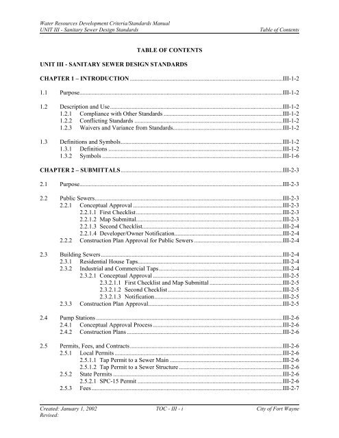
Water Resources Development Criteria/<strong>Standards</strong> ManualUNIT <strong>III</strong> - <strong>Sanitary</strong> <strong>Sewer</strong> <strong>Design</strong> <strong>Standards</strong>Table <strong>of</strong> ContentsTABLE OF CONTENTSUNIT <strong>III</strong> - SANITARY SEWER DESIGN STANDARDSCHAPTER 1 – INTRODUCTION ....................................................................................................<strong>III</strong>-1-21.1 Purpose.....................................................................................................................................<strong>III</strong>-1-21.2 Description and Use.................................................................................................................<strong>III</strong>-1-21.2.1 Compliance with Other <strong>Standards</strong> ..............................................................................<strong>III</strong>-1-21.2.2 Conflicting <strong>Standards</strong> .................................................................................................<strong>III</strong>-1-21.2.3 Waivers and Variance from <strong>Standards</strong>........................................................................<strong>III</strong>-1-21.3 Definitions and Symbols..........................................................................................................<strong>III</strong>-1-21.3.1 Definitions ..................................................................................................................<strong>III</strong>-1-21.3.2 Symbols ......................................................................................................................<strong>III</strong>-1-6CHAPTER 2 – SUBMITTALS..........................................................................................................<strong>III</strong>-2-32.1 Purpose.....................................................................................................................................<strong>III</strong>-2-32.2 Public <strong>Sewer</strong>s...........................................................................................................................<strong>III</strong>-2-32.2.1 Conceptual Approval ..................................................................................................<strong>III</strong>-2-32.2.1.1 First Checklist................................................................................................<strong>III</strong>-2-32.2.1.2 Map Submittal................................................................................................<strong>III</strong>-2-32.2.1.3 Second Checklist............................................................................................<strong>III</strong>-2-42.2.1.4 Developer/Owner Notification.......................................................................<strong>III</strong>-2-42.2.2 Construction Plan Approval for Public <strong>Sewer</strong>s ..........................................................<strong>III</strong>-2-42.3 Building <strong>Sewer</strong>s.......................................................................................................................<strong>III</strong>-2-42.3.1 Residential House Taps...............................................................................................<strong>III</strong>-2-42.3.2 Industrial and Commercial Taps.................................................................................<strong>III</strong>-2-42.3.2.1 Conceptual Approval .....................................................................................<strong>III</strong>-2-52.3.2.1.1 First Checklist and Map Submittal ................................................<strong>III</strong>-2-52.3.2.1.2 Second Checklist ...........................................................................<strong>III</strong>-2-52.3.2.1.3 Notification....................................................................................<strong>III</strong>-2-52.3.3 Construction Plan Approval........................................................................................<strong>III</strong>-2-52.4 Pump Stations ..........................................................................................................................<strong>III</strong>-2-62.4.1 Conceptual Approval Process.....................................................................................<strong>III</strong>-2-62.4.2 Construction Plans ......................................................................................................<strong>III</strong>-2-62.5 Permits, Fees, and Contracts....................................................................................................<strong>III</strong>-2-62.5.1 Local Permits ..............................................................................................................<strong>III</strong>-2-62.5.1.1 Tap Permit to a <strong>Sewer</strong> Main ..........................................................................<strong>III</strong>-2-62.5.1.2 Tap Permit to a <strong>Sewer</strong> Structure ....................................................................<strong>III</strong>-2-62.5.2 State Permits ...............................................................................................................<strong>III</strong>-2-62.5.2.1 SPC-15 Permit ...............................................................................................<strong>III</strong>-2-62.5.3 Fees .............................................................................................................................<strong>III</strong>-2-7Created: January 1, 2002 TOC - <strong>III</strong> - i <strong>City</strong> <strong>of</strong> <strong>Fort</strong> <strong>Wayne</strong>Revised:
Water Resources Development Criteria/<strong>Standards</strong> ManualUNIT <strong>III</strong> - <strong>Sanitary</strong> <strong>Sewer</strong> <strong>Design</strong> <strong>Standards</strong>Table <strong>of</strong> Contents2.5.3.1 Permit Application Fees for Local Permits....................................................<strong>III</strong>-2-72.5.3.2 Permit Application Fees for State Permits.....................................................<strong>III</strong>-2-72.5.3.3 Additional Fees..............................................................................................<strong>III</strong>-2-72.5.4 Contracts .....................................................................................................................<strong>III</strong>-2-8CHAPTER 3 – PUBLIC SEWERS ...................................................................................................<strong>III</strong>-3-33.1 Purpose.....................................................................................................................................<strong>III</strong>-3-33.2 General Improvement Location Criteria ..................................................................................<strong>III</strong>-3-33.3 Horizontal Alignment Criteria .................................................................................................<strong>III</strong>-3-33.3.1 General........................................................................................................................<strong>III</strong>-3-33.3.2 Placement in Existing Rights-<strong>of</strong>-Way and Easements................................................<strong>III</strong>-3-33.3.3 Stationing....................................................................................................................<strong>III</strong>-3-43.3.4 Minimum Horizontal Separation from Water Lines ...................................................<strong>III</strong>-3-43.3.5 Rear Lot Alignment ....................................................................................................<strong>III</strong>-3-43.3.6 Minimum Distance from Additional Utilities.............................................................<strong>III</strong>-3-43.3.7 Location in Relation to Streams and Waterways........................................................<strong>III</strong>-3-53.4 Vertical Alignment Criteria .....................................................................................................<strong>III</strong>-3-53.4.1 <strong>Sewer</strong> Depths ..............................................................................................................<strong>III</strong>-3-53.4.2 Minimum Vertical Separation from Water Lines .......................................................<strong>III</strong>-3-53.4.3 Stream and Waterway Crossings ................................................................................<strong>III</strong>-3-63.4.4 <strong>Sewer</strong> Elevations.........................................................................................................<strong>III</strong>-3-63.4.5 Flooding and Ponding Areas.......................................................................................<strong>III</strong>-3-63.5 General Procedures ..................................................................................................................<strong>III</strong>-3-63.6 <strong>Sanitary</strong> <strong>Sewer</strong> Service Area Map ...........................................................................................<strong>III</strong>-3-73.7 <strong>Design</strong> Flow.............................................................................................................................<strong>III</strong>-3-83.7.1 General........................................................................................................................<strong>III</strong>-3-83.7.2 Collector <strong>Sewer</strong>s .........................................................................................................<strong>III</strong>-3-83.7.3 Interceptor <strong>Sewer</strong>s ......................................................................................................<strong>III</strong>-3-83.7.4 Average Daily Flow (ADF) ........................................................................................<strong>III</strong>-3-83.7.4.1 Development Flows .......................................................................................<strong>III</strong>-3-83.7.4.2 Undeveloped Land for Future Flows .............................................................<strong>III</strong>-3-83.7.5 Peak <strong>Design</strong> Flow (PDF) ............................................................................................<strong>III</strong>-3-93.7.6 Flow Metering.............................................................................................................<strong>III</strong>-3-93.8 Hydraulic <strong>Design</strong> Criteria........................................................................................................<strong>III</strong>-3-93.8.1 General........................................................................................................................<strong>III</strong>-3-93.8.2 Hydraulic Grade Line .................................................................................................<strong>III</strong>-3-93.8.3 Velocity.....................................................................................................................<strong>III</strong>-3-103.8.4 Slopes........................................................................................................................<strong>III</strong>-3-103.8.4.1 Slope Between Manholes .........................................................................<strong>III</strong>-3-103.8.5 Changes in <strong>Sewer</strong> Size..............................................................................................<strong>III</strong>-3-103.8.6 Minimization <strong>of</strong> Solids Deposition...........................................................................<strong>III</strong>-3-11Created: January 1, 2002 TOC - <strong>III</strong> - ii <strong>City</strong> <strong>of</strong> <strong>Fort</strong> <strong>Wayne</strong>Revised:
Water Resources Development Criteria/<strong>Standards</strong> ManualUNIT <strong>III</strong> - <strong>Sanitary</strong> <strong>Sewer</strong> <strong>Design</strong> <strong>Standards</strong>Table <strong>of</strong> Contents3.9 Hydraulic Computations ........................................................................................................<strong>III</strong>-3-113.10 <strong>Sewer</strong> Pipe .............................................................................................................................<strong>III</strong>-3-113.11 Manholes................................................................................................................................<strong>III</strong>-3-123.11.1 General......................................................................................................................<strong>III</strong>-3-123.11.2 Manhole Locations ...................................................................................................<strong>III</strong>-3-123.11.3 Manhole Spacing ......................................................................................................<strong>III</strong>-3-123.11.4 Manhole Diameter ....................................................................................................<strong>III</strong>-3-123.11.5 Flow Channel............................................................................................................<strong>III</strong>-3-133.11.6 Bench ........................................................................................................................<strong>III</strong>-3-133.11.7 Watertight Bolt-Down Construction.........................................................................<strong>III</strong>-3-143.11.8 External Drop Inlets..................................................................................................<strong>III</strong>-3-143.11.9 Adjustment Rings .....................................................................................................<strong>III</strong>-3-143.12 Stubs.......................................................................................................................................<strong>III</strong>-3-143.13 Siphons...................................................................................................................................<strong>III</strong>-3-143.14 Floatation ...............................................................................................................................<strong>III</strong>-3-143.15 Anchors..................................................................................................................................<strong>III</strong>-3-143.16 Concrete Encasements ...........................................................................................................<strong>III</strong>-3-153.17 Railroad Crossings.................................................................................................................<strong>III</strong>-3-153.17.1 Criteria ......................................................................................................................<strong>III</strong>-3-153.17.2 Railroad Conflict Drawings ......................................................................................<strong>III</strong>-3-163.18 Highway Crossings ................................................................................................................<strong>III</strong>-3-163.19 Casing Pipe and Tunnel Liners..............................................................................................<strong>III</strong>-3-173.19.1 Tunnel Liners............................................................................................................<strong>III</strong>-3-173.19.2 Pipe Casing ...............................................................................................................<strong>III</strong>-3-17CHAPTER 4 – BUILDING SEWERS ..............................................................................................<strong>III</strong>-4-24.1 Purpose.....................................................................................................................................<strong>III</strong>-4-24.2 Prohibition Against Clear Water Discharges...........................................................................<strong>III</strong>-4-24.3 Buildings Served.....................................................................................................................<strong>III</strong>-4-24.3.1 Maximum Number <strong>of</strong> Buildings Served.................................................................<strong>III</strong>-4-24.3.2 Gravity <strong>Sewer</strong> Service............................................................................................<strong>III</strong>-4-24.3.3 Non-Gravity <strong>Sewer</strong> Service....................................................................................<strong>III</strong>-4-24.4 Connection Permits and Building <strong>Sewer</strong> Inspection...............................................................<strong>III</strong>-4-34.4.1 Connection Permits.................................................................................................<strong>III</strong>-4-3Created: January 1, 2002 TOC - <strong>III</strong> - iii <strong>City</strong> <strong>of</strong> <strong>Fort</strong> <strong>Wayne</strong>Revised:
Water Resources Development Criteria/<strong>Standards</strong> ManualUNIT <strong>III</strong> - <strong>Sanitary</strong> <strong>Sewer</strong> <strong>Design</strong> <strong>Standards</strong>Table <strong>of</strong> Contents4.4.2 Building <strong>Sewer</strong> Inspection......................................................................................<strong>III</strong>-4-34.5 Building <strong>Sewer</strong> Responsibility ...............................................................................................<strong>III</strong>-4-34.6 Hydraulic <strong>Design</strong> Criteria.......................................................................................................<strong>III</strong>-4-44.6.1 Plumbing Codes......................................................................................................<strong>III</strong>-4-44.6.2 Minimum Slopes......................................................................................................<strong>III</strong>-4-44.7 Building <strong>Sewer</strong> Connection to Public <strong>Sewer</strong>...........................................................................<strong>III</strong>-4-44.8 Building <strong>Sewer</strong> Structures .......................................................................................................<strong>III</strong>-4-44.8.1 Cleanouts .................................................................................................................<strong>III</strong>-4-44.8.2 Grease and Sand Traps ............................................................................................<strong>III</strong>-4-44.8.3 Inspection Manholes................................................................................................<strong>III</strong>-4-54.9 Building <strong>Sewer</strong> Pipe ................................................................................................................<strong>III</strong>-4-5CHAPTER 5 – PUMP STATIONS ...................................................................................................<strong>III</strong>-5-35.1 Purpose.....................................................................................................................................<strong>III</strong>-5-35.2 Submittal Requirements...........................................................................................................<strong>III</strong>-5-35.2.1 Conceptual Approval Process.....................................................................................<strong>III</strong>-5-35.2.1.1 Concept <strong>Design</strong> Plan......................................................................................<strong>III</strong>-5-35.2.1.2 Engineering Report........................................................................................<strong>III</strong>-5-45.2.2 Final <strong>Design</strong> Requirements.........................................................................................<strong>III</strong>-5-55.3 <strong>Design</strong> Approach .....................................................................................................................<strong>III</strong>-5-75.3.1 Approvals....................................................................................................................<strong>III</strong>-5-75.3.2 Service Level ..............................................................................................................<strong>III</strong>-5-75.3.3 Justification.................................................................................................................<strong>III</strong>-5-85.4 <strong>Design</strong> Criteria .......................................................................................................................<strong>III</strong>-5-85.4.1 General .......................................................................................................................<strong>III</strong>-5-85.4.1.1 Protection Against Flooding ..........................................................................<strong>III</strong>-5-85.4.1.2 Parking Requirements....................................................................................<strong>III</strong>-5-85.4.1.3 Compliance with OSHA Safety Requirements..............................................<strong>III</strong>-5-85.4.2 Process .......................................................................................................................<strong>III</strong>-5-95.4.2.1 Wet Well........................................................................................................<strong>III</strong>-5-95.4.2.2 Valves and Valve Vaults................................................................................<strong>III</strong>-5-95.4.2.3 Force Mains .................................................................................................<strong>III</strong>-5-105.4.2.3.1 General ........................................................................................<strong>III</strong>-5-105.4.2.3.2 Air and Vacuum Relief Valves....................................................<strong>III</strong>-5-105.4.2.3.3 Friction Losses in Force Mains ...................................................<strong>III</strong>-5-105.4.2.4 System Head Curve .....................................................................................<strong>III</strong>-5-115.4.2.5 Buoyancy .....................................................................................................<strong>III</strong>-5-115.4.2.6 Force Main Pressure and Water Hammer....................................................<strong>III</strong>-5-115.4.2.7 Odor Control................................................................................................<strong>III</strong>-5-11Created: January 1, 2002 TOC - <strong>III</strong> - iv <strong>City</strong> <strong>of</strong> <strong>Fort</strong> <strong>Wayne</strong>Revised:
Water Resources Development Criteria/<strong>Standards</strong> ManualUNIT <strong>III</strong> - <strong>Sanitary</strong> <strong>Sewer</strong> <strong>Design</strong> <strong>Standards</strong>Table <strong>of</strong> Contents5.5 Pumps.....................................................................................................................................<strong>III</strong>-5-125.5.1 General......................................................................................................................<strong>III</strong>-5-125.5.2 Pump Openings.........................................................................................................<strong>III</strong>-5-125.5.3 Intake ........................................................................................................................<strong>III</strong>-5-125.5.4 Pump Guide Rail System..........................................................................................<strong>III</strong>-5-125.5.5 Required Pump Information .....................................................................................<strong>III</strong>-5-125.6 Electrical ................................................................................................................................<strong>III</strong>-5-135.6.1 General......................................................................................................................<strong>III</strong>-5-135.6.2 Applicable <strong>Standards</strong> and Codes ..............................................................................<strong>III</strong>-5-145.6.3 Pump Control............................................................................................................<strong>III</strong>-5-155.6.3.1 Automatic Sequence Operation ...................................................................<strong>III</strong>-5-155.6.3.2 Pump Control Panel.....................................................................................<strong>III</strong>-5-155.6.3.3 Control Settings ...........................................................................................<strong>III</strong>-5-165.6.3.4 Level Detection............................................................................................<strong>III</strong>-5-175.6.3.5 Operator Interface........................................................................................<strong>III</strong>-5-175.6.3.6 Pump Interlock.............................................................................................<strong>III</strong>-5-185.6.4 Alarm System ...........................................................................................................<strong>III</strong>-5-185.6.4.1 Local Alarms................................................................................................<strong>III</strong>-5-185.6.4.2 Telemetry Alarms ........................................................................................<strong>III</strong>-5-195.6.5 Emergency Power .....................................................................................................<strong>III</strong>-5-195.7 Metering and Sample Points ..................................................................................................<strong>III</strong>-5-19LIST OF EXHIBITS<strong>III</strong>-2-1 First Checklist<strong>III</strong>-2-2 Area Map<strong>III</strong>-2-3 <strong>Sanitary</strong> <strong>Sewer</strong> Service Area Map<strong>III</strong>-2-4 Second Checklist<strong>III</strong>-2-5 <strong>Sanitary</strong> <strong>Sewer</strong> Facilities Review Checklist<strong>III</strong>-2-6 Minimum Construction Plan Requirements Checklist<strong>III</strong>-2-7 IDEM Local Permitting Forms<strong>III</strong>-3-1 Wastewater Flows<strong>III</strong>-3-2 Peaking Factors<strong>III</strong>-3-3 Minimum Allowable SlopesCreated: January 1, 2002 TOC - <strong>III</strong> - v <strong>City</strong> <strong>of</strong> <strong>Fort</strong> <strong>Wayne</strong>Revised:
Water Resources Development Criteria/<strong>Standards</strong> Manual Chapter 1UNIT <strong>III</strong> - <strong>Sanitary</strong> <strong>Sewer</strong> <strong>Design</strong> <strong>Standards</strong>IntroductionTABLE OF CONTENTSCHAPTER 1 – INTRODUCTION .......................................................................................................<strong>III</strong>-1-21.1 Purpose.....................................................................................................................................<strong>III</strong>-1-21.2 Description and Use.................................................................................................................<strong>III</strong>-1-21.2.1 Compliance with Other <strong>Standards</strong> ..............................................................................<strong>III</strong>-1-21.2.2 Conflicting <strong>Standards</strong> .................................................................................................<strong>III</strong>-1-21.2.3 Waivers and Variance from <strong>Standards</strong>........................................................................<strong>III</strong>-1-21.3 Definitions and Symbols..........................................................................................................<strong>III</strong>-1-21.3.1 Definitions ..................................................................................................................<strong>III</strong>-1-21.3.2 Symbols ......................................................................................................................<strong>III</strong>-1-6Created: January 1, 2002 <strong>III</strong> - 1 - 1 <strong>City</strong> <strong>of</strong> <strong>Fort</strong> <strong>Wayne</strong>Revised:
Water Resources Development Criteria/<strong>Standards</strong> Manual Chapter 1UNIT <strong>III</strong> - <strong>Sanitary</strong> <strong>Sewer</strong> <strong>Design</strong> <strong>Standards</strong>Introduction1.1 PurposeCHAPTER 1 - INTRODUCTIONThe purpose <strong>of</strong> these design standards is to provide guidance for the design <strong>of</strong> sanitary sewersystems and pump stations. These standards set forth minimum criteria for the design andconstruction <strong>of</strong> all such facilities within the jurisdiction <strong>of</strong> the <strong>City</strong> <strong>of</strong> <strong>Fort</strong> <strong>Wayne</strong>. The Chapters<strong>of</strong> this <strong>Unit</strong> outline the general requirements necessary for design. This <strong>Unit</strong> <strong>III</strong> shall be used inconjunction with <strong>Unit</strong> <strong>III</strong> <strong>of</strong> the <strong>Design</strong> Manual. The <strong>Design</strong> Manual further details designprocedures and methods, provides more comprehensive design guidelines and methodology, andcontains computation worksheets to assist in sanitary sewer design.1.2 Description and Use1.2.1 Compliance with Other <strong>Standards</strong>Compliance with this standard does not eliminate the need to comply with otherapplicable <strong>City</strong>, County, State and Federal ordinances and regulations. This includes, butis not limited to, the submission and approval <strong>of</strong> preliminary and final subdivision plats,IDEM permits (IDEM or <strong>City</strong> issued) for sanitary facilities construction, building andzoning permits, construction inspections, appeals, and similar matters.1.2.2 Conflicting <strong>Standards</strong>The provisions <strong>of</strong> this document shall be deemed as additional requirements to minimumstandards required by other applicable ordinances and standards. In the case <strong>of</strong>conflicting requirements, the most restrictive shall apply.1.2.3 Waivers and Variance from <strong>Standards</strong>Alternative sanitary sewer methods and materials on occasion may be warranted, and avariance from these standards may be permitted. A written request for variance must bemade to Water Resources. The request must be based upon sound engineering practiceand judgement, and must be supported by adequate justification and data. If a variance isgranted, it will apply only to the specific project for which approval is sought. Variancesand waivers granted by the Department <strong>of</strong> Water Resources shall apply only to thesanitary sewer design standards. Variance from other <strong>City</strong>, State and Federal regulationsand standards can not be granted by Water Resources.1.3 Definitions and Symbols1.3.1 DefinitionsThe following are definitions and symbols commonly used in the design <strong>of</strong> sanitarysewers and pump stations.Adjustment Ring – A cylindrical ring, usually comprised <strong>of</strong> concrete, secured on top <strong>of</strong> amanhole upon which the frame will rest.Created: January 1, 2002 <strong>III</strong> - 1 - 2 <strong>City</strong> <strong>of</strong> <strong>Fort</strong> <strong>Wayne</strong>Revised:
Water Resources Development Criteria/<strong>Standards</strong> Manual Chapter 1UNIT <strong>III</strong> - <strong>Sanitary</strong> <strong>Sewer</strong> <strong>Design</strong> <strong>Standards</strong>IntroductionAdministering Authority – The designated unit <strong>of</strong> government given the authority toissue permitsAverage Daily Flow – Average 24-hour dry weather flow, including a nominal amount <strong>of</strong>infiltration, within a sewer.Backfill – Earth and/or other material used to replace material removed from trenches orother excavations during construction activities. The backfill lies above the pipebedding.Bedding – The portion <strong>of</strong> backfill which encases the sewer pipe to a minimum depthabove and below the barrel <strong>of</strong> the pipe. The bedding serves as the pipe support.Board – The Board <strong>of</strong> Public Works for the <strong>City</strong> <strong>of</strong> <strong>Fort</strong> <strong>Wayne</strong> and any subordinateemployee to whom the Board shall specifically delegate the responsibility authorized bythese standards.Building <strong>Sewer</strong> – Private sewers which connect building plumbing to public sewers.Building sewers normally begin outside the building foundation.Buoyancy – The act <strong>of</strong> supporting a floating body, including the tendency to float anempty pipe by exterior hydraulic pressure.Capacity <strong>of</strong> Gravity <strong>Sanitary</strong> <strong>Sewer</strong> Facility – The maximum flow that can be conveyedor stored in a sanitary sewer or conduit without surcharging.<strong>City</strong> Utility <strong>Design</strong>ed Project – Project designed by <strong>Fort</strong> <strong>Wayne</strong> in-house staff.Cleanout – A pipe or some other opening through which a device may be run to unplug asewer.Collar – A monolithic concrete encasement for support <strong>of</strong> a conduitCollector <strong>Sewer</strong> – <strong>Sewer</strong> which is primarily installed to receive wastewater directly fromproperty service connections and convey the wastewater to an interceptor line.Crown <strong>of</strong> Pipe – The highest inside part <strong>of</strong> a pipe or conduit.Development – Any man-made change to improved or unimproved real estate, includingbut not limited to, buildings, or other structures, mining, dredging, filling, grading,paving, excavation, substantial improvements, placement <strong>of</strong> mobile homes, subdivision<strong>of</strong> land, in-fill or drilling operations.Effluent – Water or wastewater that flows from a facility such as a pump station ortreatment process.Encasement – The enclosing or surrounding <strong>of</strong> a conduit with concrete or other suitablematerial.Created: January 1, 2002 <strong>III</strong> - 1 - 3 <strong>City</strong> <strong>of</strong> <strong>Fort</strong> <strong>Wayne</strong>Revised:
Water Resources Development Criteria/<strong>Standards</strong> Manual Chapter 1UNIT <strong>III</strong> - <strong>Sanitary</strong> <strong>Sewer</strong> <strong>Design</strong> <strong>Standards</strong>IntroductionForce Main – A pipe under internal pressure created by forces on the discharge side <strong>of</strong> apump.Grade – The inclination or slope <strong>of</strong> a conduit or natural ground surface usually expressedin terms <strong>of</strong> the percentage the vertical rise (or fall) bears to the corresponding horizontaldistance.Grease Trap – Device which collects organic substances including fats, vegetable andmineral oils, waxes, fatty acids from soaps, and other hydrocarbons before they enter thesewer system thus reducing the risk <strong>of</strong> adhesion problems in sewers.Hydraulic Grade Line – Measure <strong>of</strong> pressure head available at specific points within asewer system. The hydraulic grade line is a line connecting the points to which the liquidwould rise at various places along any pipe if piezometer tubes were inserted in theliquid.IDEM – Indiana Department <strong>of</strong> Environmental Management.IDNR – Indiana Department <strong>of</strong> Natural Resources.INDOT – Indiana Department <strong>of</strong> Transportation.Infiltration – Groundwater that enters the sewer system via such means as pipe cracks,joints, connections, or defects in manhole structures.Inflow – Surface water which enters the sanitary sewer system via an illegal drainconnection (foundation drain, ro<strong>of</strong> drain, yard drain, inlet structure, storm sewer crossconnection, or sump pump) or from sources such as leaks around manhole covers.Interceptor <strong>Sewer</strong> – Principal sewer to which collector sewers are tributary. Interceptorsewers convey the wastewater to treatment or other disposal facilities.Invert – The bottom or lowest elevation <strong>of</strong> the internal cross-section <strong>of</strong> a conduit orsewer.Inverted Siphon – A sewer line which drops below the hydraulic gradient.Land Disturbing Activity – Any man-made changes <strong>of</strong> the land surface including, but notlimited to, removing vegetative cover, excavating, filling, transporting and grading <strong>of</strong>soils, sediment or rock. Agricultural land disturbing activities are excluded.Lateral – Alternate term for building sewer.Lift Station – Any arrangement <strong>of</strong> pumps, piping, valves, and controls which conveywastewater to or over a higher elevation.Manhole – <strong>Sanitary</strong> sewer structure through which a person may enter to gain access toan underground sanitary sewer or enclosed structure.Created: January 1, 2002 <strong>III</strong> - 1 - 4 <strong>City</strong> <strong>of</strong> <strong>Fort</strong> <strong>Wayne</strong>Revised:
Water Resources Development Criteria/<strong>Standards</strong> Manual Chapter 1UNIT <strong>III</strong> - <strong>Sanitary</strong> <strong>Sewer</strong> <strong>Design</strong> <strong>Standards</strong>IntroductionMonolithic – Cast-in-place as one unit.Non-<strong>City</strong> Utility <strong>Design</strong>ed Project – Project designed by outside consultant, engineer,developer, etc.Off-site – Everything not on-site.On-site – The entire area included in the legal description <strong>of</strong> the land on which thedevelopment or land disturbing activities take place.Peak Hourly Flow – The largest volume <strong>of</strong> flow to be received during a continous 24-hour period.Permanent Easement – A permanent right-<strong>of</strong>-way to use a described parcel <strong>of</strong> land forthe purposes to construct, operate, control, maintain, reconstruct, or remove a sewer lineand appurtenances along, under, and across said easement.Permit – Written permission to do something from agency with authority to controloperation.Plans – Official drawings or reproductions <strong>of</strong> drawings pertaining to the work associatedwith specific project.Population, Equivalent – A hypothetical number <strong>of</strong> persons for which flow contributionsare calculated.Population, Saturation – The actual (equivalent) population that exists or would existwhen an area is fully developed.Precast – An item which is formed or molded and distributed by the manufacturer as acomplete unit.Private <strong>Sewer</strong> – <strong>Sewer</strong> owned and maintained by a private person or company.Public <strong>Sewer</strong> – <strong>Sewer</strong> to the use <strong>of</strong> which all owners <strong>of</strong> abutting property have equalrights to and is controlled and maintained by the <strong>City</strong> <strong>of</strong> <strong>Fort</strong> <strong>Wayne</strong> or other publicauthority.<strong>Sanitary</strong> <strong>Sewer</strong> – A pipe or conduit designed to convey wastewater. Storm, surface, andground waters together with unpolluted industrial wastewaters are not permitted withinsanitary sewers.Service Area – A geographical area served by a public utility or sewage collectionsystem.Springline <strong>of</strong> Pipe – The horizontal midpoint <strong>of</strong> a sewer pipe.Submersible Pump – A pump capable <strong>of</strong> being fully placed beneath a water surface.Created: January 1, 2002 <strong>III</strong> - 1 - 5 <strong>City</strong> <strong>of</strong> <strong>Fort</strong> <strong>Wayne</strong>Revised:
Water Resources Development Criteria/<strong>Standards</strong> Manual Chapter 1UNIT <strong>III</strong> - <strong>Sanitary</strong> <strong>Sewer</strong> <strong>Design</strong> <strong>Standards</strong>IntroductionSurcharge – A condition in which a sewer or conduit does not possess enough capacityto convey the total amount <strong>of</strong> flow within the system. The amount <strong>of</strong> surcharge ismeasured by the volume or rate <strong>of</strong> excess flow or by the height <strong>of</strong> the elevated hydraulicgrade line.Stub – Short length <strong>of</strong> sewer segment tapped into existing system allowing for futureconnection.Ten State <strong>Standards</strong> – “Recommended <strong>Standards</strong> for Wastewater Facilities <strong>of</strong> the GreatLakes-Upper Mississippi River Board <strong>of</strong> State and Provincial Public Health andEnvironmental Managers.” 1997 Edition.Temporary Easement – The temporary use <strong>of</strong> land for the purposes <strong>of</strong> constructing andplacing in operation a sewer and its appurtenances. The temporary sewer easement shallexpire a minimum <strong>of</strong> one year from the date <strong>of</strong> adoption by the Board <strong>of</strong> Public Worksand Safety, or on the date specified in the easement instrument.Wastewater – The water supply <strong>of</strong> a <strong>City</strong> after is has been fouled by a variety <strong>of</strong> uses.From the standpoint <strong>of</strong> sources <strong>of</strong> generation, wastewater may be defined as acombination <strong>of</strong> the liquid- or water-carried wastes removed from residences, institutions,and commercial and industrial establishments.Wet Well – A short-term storage tank containing a pump or pump entrance into whichraw wastewater is conveyed.1.3.2 SymbolsSymbols used throughout these standards include:Symbols Definition <strong>Unit</strong>A cross sectional area ft 2cfs cubic feet per second cfsd or D inside diameter <strong>of</strong> pipe ftft/s feet per second ft/sg acceleration due to gravity (32.2) ft/s 2gpd gallons per day gpdgpm gallons per minute gpmL flow length ftMGD million gallons per day MGDn Manning’s Roughness Coefficient -Created: January 1, 2002 <strong>III</strong> - 1 - 6 <strong>City</strong> <strong>of</strong> <strong>Fort</strong> <strong>Wayne</strong>Revised:
Water Resources Development Criteria/<strong>Standards</strong> Manual Chapter 1UNIT <strong>III</strong> - <strong>Sanitary</strong> <strong>Sewer</strong> <strong>Design</strong> <strong>Standards</strong>Introductionpsi pounds per square inch psiQ flow within sanitary sewer or conduit ft 3 /s, MGD, gpmr radius <strong>of</strong> pipe ftr H hydraulic radius (area/wetted perimeter) fts slope ft/ftV or v velocity ft/sEND CHAPTER 1Created: January 1, 2002 <strong>III</strong> - 1 - 7 <strong>City</strong> <strong>of</strong> <strong>Fort</strong> <strong>Wayne</strong>Revised:
Water Resources Development Criteria/<strong>Standards</strong> Manual Chapter 2UNIT <strong>III</strong> - <strong>Sanitary</strong> <strong>Sewer</strong> <strong>Design</strong> <strong>Standards</strong>SubmittalsCHAPTER 2 – SUBMITTALSTABLE OF CONTENTS2.1 Purpose...................................................................................................................................<strong>III</strong>-2-32.2 Public <strong>Sewer</strong>s.........................................................................................................................<strong>III</strong>-2-32.2.1 Conceptual Approval ................................................................................................<strong>III</strong>-2-32.2.1.1 First Checklist..............................................................................................<strong>III</strong>-2-32.2.1.2 Map Submittal..............................................................................................<strong>III</strong>-2-32.2.1.3 Second Checklist..........................................................................................<strong>III</strong>-2-42.2.1.4 Developer/Owner Notification.....................................................................<strong>III</strong>-2-42.2.2 Construction Plan Approval for Public <strong>Sewer</strong>s ........................................................<strong>III</strong>-2-42.3 Building <strong>Sewer</strong>s.....................................................................................................................<strong>III</strong>-2-42.3.1 Residential House Taps.............................................................................................<strong>III</strong>-2-42.3.2 Industrial and Commercial Taps...............................................................................<strong>III</strong>-2-42.3.2.1 Conceptual Approval ...................................................................................<strong>III</strong>-2-52.3.2.1.1 First Checklist and Map Submittal ..............................................<strong>III</strong>-2-52.3.2.1.2 Second Checklist .........................................................................<strong>III</strong>-2-52.3.2.1.3 Notification..................................................................................<strong>III</strong>-2-52.3.3 Construction Plan Approval for Building <strong>Sewer</strong>s ....................................................<strong>III</strong>-2-52.4 Pump Stations ........................................................................................................................<strong>III</strong>-2-62.4.1 Conceptual Approval Process...................................................................................<strong>III</strong>-2-62.4.2 Construction Plans ....................................................................................................<strong>III</strong>-2-62.5 Permits, Fees, and Contracts..................................................................................................<strong>III</strong>-2-62.5.1 Local Permits ............................................................................................................<strong>III</strong>-2-62.5.1.1 Tap Permit to a <strong>Sewer</strong> Main ........................................................................<strong>III</strong>-2-62.5.1.2 Tap Permit to a <strong>Sewer</strong> Structure ..................................................................<strong>III</strong>-2-62.5.2 State Permits .............................................................................................................<strong>III</strong>-2-62.5.2.1 SPC-15 Permit .............................................................................................<strong>III</strong>-2-62.5.3 Fees ...........................................................................................................................<strong>III</strong>-2-72.5.3.1 Permit Application Fees for Local Permits..................................................<strong>III</strong>-2-72.5.3.2 Permit Application Fees for State Permits...................................................<strong>III</strong>-2-72.5.3.3 Additional Fees............................................................................................<strong>III</strong>-2-72.5.4 Contracts ...................................................................................................................<strong>III</strong>-2-8EXHIBITS<strong>III</strong>-2-1 First Checklist<strong>III</strong>-2-2 Area Map<strong>III</strong>-2-3 <strong>Sanitary</strong> <strong>Sewer</strong> Service Area Map<strong>III</strong>-2-4 Second ChecklistCreated: January 1, 2002 <strong>III</strong> - 2 - 1 <strong>City</strong> <strong>of</strong> <strong>Fort</strong> <strong>Wayne</strong>Revised:
Water Resources Development Criteria/<strong>Standards</strong> Manual Chapter 2UNIT <strong>III</strong> - <strong>Sanitary</strong> <strong>Sewer</strong> <strong>Design</strong> <strong>Standards</strong>Submittals<strong>III</strong>-2-5 <strong>Sanitary</strong> <strong>Sewer</strong> Facilities Review Checklist<strong>III</strong>-2-6 Minimum Construction Plan Requirements Checklist<strong>III</strong>-2-7 IDEM Local Permitting FormsCreated: January 1, 2002 <strong>III</strong> - 2 - 2 <strong>City</strong> <strong>of</strong> <strong>Fort</strong> <strong>Wayne</strong>Revised:
Water Resources Development Criteria/<strong>Standards</strong> Manual Chapter 2UNIT <strong>III</strong> - <strong>Sanitary</strong> <strong>Sewer</strong> <strong>Design</strong> <strong>Standards</strong>Submittals2.1 PurposeCHAPTER 2 – SUBMITTALSThe purpose <strong>of</strong> this chapter is to outline the minimum requirements for the submittal <strong>of</strong> plans forproposed sanitary sewer improvements. The requirements for public sewers, building sewers,and pump stations are all discussed. These submittal requirements are intended to supplement the<strong>Design</strong> Manual and Chapter 51 <strong>of</strong> the <strong>Fort</strong> <strong>Wayne</strong> Code <strong>of</strong> Ordinances and the <strong>Fort</strong> <strong>Wayne</strong> WaterPollution Control Utility Rules and Regulations.Submittal requirements shall be discussed with the staff <strong>of</strong> Water Resources during thepreliminary planning phase for all projects. The size and type <strong>of</strong> submittal typically varies withthe size and type <strong>of</strong> the project and details will be developed with the project manager designatedby Water Resources.Preparation <strong>of</strong> all project submittals shall be the responsibility <strong>of</strong> the project designer.2.2 Public <strong>Sewer</strong>s2.2.1 Conceptual Approval2.2.1.1 First ChecklistConceptual approval will begin with completion <strong>of</strong> the First Checklist found inExhibit <strong>III</strong>-2-1. This checklist addresses planning issues and submittalrequirements. The form shall be completed and submitted to Water Resourceswith an Area Map or Drainage Map, whichever is deemed necessary by the firstChecklist.2.2.1.2 Map SubmittalTwo (2) copies a general Area Map or <strong>Sanitary</strong> <strong>Sewer</strong> Service Area Map will berequired. A general Area Map shall generally include the following:a. Boundaries <strong>of</strong> the proposed developmentb. Point <strong>of</strong> connection to existing sewer facilitiesc. Intended land used. Estimate flow to be generated by the developmentAn example Area Map is included as Exhibit <strong>III</strong>-2-2. <strong>Sanitary</strong> <strong>Sewer</strong> ServiceArea Maps, an example <strong>of</strong> which is found in Exhibit <strong>III</strong>-2-3, shall be prepared inaccordance with Section 3.6. It should be noted that although an Area Map maybe acceptable for conceptual approval, a more comprehensive <strong>Sanitary</strong> <strong>Sewer</strong>Service Area Map will be required for the actual project design. Accompanyingthe request for Conceptual Approval and map submittal, shall be a statement <strong>of</strong>anticipated project start and completion dates.Created: January 1, 2002 <strong>III</strong> - 2 - 3 <strong>City</strong> <strong>of</strong> <strong>Fort</strong> <strong>Wayne</strong>Revised:
Water Resources Development Criteria/<strong>Standards</strong> Manual Chapter 2UNIT <strong>III</strong> - <strong>Sanitary</strong> <strong>Sewer</strong> <strong>Design</strong> <strong>Standards</strong>Submittals2.2.1.3 Second ChecklistDevelopment Services will review the submittal and address capacity issues andcost <strong>of</strong> service concerns using the Second Checklist found in Exhibit <strong>III</strong>-2-4.Additional Water Resources' Departments and The Board <strong>of</strong> Public Works willbe consulted on an as-needed basis.2.2.1.4 Developer/Owner NotificationUpon review <strong>of</strong> the submittal, Development Services will issue a statementaddressing the existing system’s ability to receive the proposed flow. Thestatement will include an item expressing the <strong>City</strong>’s acceptance or denial <strong>of</strong>service to the proposed development and, if relevant, an explanation for the basis<strong>of</strong> denial.2.2.2 Construction Plan Approval for Public <strong>Sewer</strong>s2.3 Building <strong>Sewer</strong>sUpon granting <strong>of</strong> Conceptual Approval, the design engineer or developer shall completeconstruction plans and specifications for the sanitary sewer project in accordance with allguidelines outlined in this Manual and additional provisions as found in the <strong>Design</strong>Manual. The checklist found in Exhibit <strong>III</strong>-2-5 shall serve as the guideline for thesubmittal <strong>of</strong> construction plans. The items called for in the Exhibit shall be submitted inorder for Development Services to review the plans. The checklist found as Exhibit <strong>III</strong>-2-6 will be utilized to assess the completeness <strong>of</strong> the construction plans.Development Services will review the construction plans and issue written comments onthe submittal. Comments received from Development Services shall be addressed by thedesign engineer or developer and plans shall be appropriately updated. Upon completion<strong>of</strong> all Water Resource requirements, an approval letter shall be issued.2.3.1 Residential House Taps<strong>Sewer</strong> taps for residential connections will require sewer tap permits. Permitrequirements shall be in accordance with Section 2.5.1. A fee will be assessed based onservice size and connection point. Section 2.5.3 addresses fee requirements.2.3.2 Industrial and Commercial TapsIn general, the requirements for industrial and commercial taps shall be as described inthe following sections. Adherence to all Federal, State, and local regulations, codes, andstatutes is also required.In addition, all requirements <strong>of</strong> Chapter 51 <strong>of</strong> the <strong>Fort</strong> <strong>Wayne</strong> Code <strong>of</strong> Ordinances,Sections 51.030 through 51.041, are hereby incorporated into the design standards forcommercial and industrial wastes. All submittals shall be transmitted to Water Resourcesas part <strong>of</strong> the First Checklist.Created: January 1, 2002 <strong>III</strong> - 2 - 4 <strong>City</strong> <strong>of</strong> <strong>Fort</strong> <strong>Wayne</strong>Revised:
Water Resources Development Criteria/<strong>Standards</strong> Manual Chapter 2UNIT <strong>III</strong> - <strong>Sanitary</strong> <strong>Sewer</strong> <strong>Design</strong> <strong>Standards</strong>Submittals2.3.2.1 Conceptual ApprovalThe need for conceptual approval will be based on the complexity <strong>of</strong> theparticular building sewer connection. It is recommended that DevelopmentServices be contacted to discuss specific building sewer submittal requirementson a case-by-case basis. The following sections outline the general, formalsubmittal process.2.3.2.1.1 First Checklist and Map SubmittalConceptual approval will begin with completion <strong>of</strong> the FirstChecklist found in Exhibit <strong>III</strong>-2-1. The checklist addresses planningissues and submittal requirements. The form shall be completed andsubmitted to Water Resources with an Area Map. Two copies <strong>of</strong> themap will be required. The Area Map should be created inaccordance with the previous Section 2.2.1.2. Accompanying therequest for Conceptual Approval and map submittal, shall be astatement <strong>of</strong> anticipated project start and completion dates.2.3.2.1.2 Second ChecklistWater Resources will review the submittal and address capacityissues and cost <strong>of</strong> service concerns. Water Resources will utilize theSecond Checklist found in Exhibit <strong>III</strong>-2-2 to address relevant issues.Additional Water Resources' Departments and the Board <strong>of</strong> PublicWorks will be consulted on an as-needed basis.2.3.2.1.3 NotificationUpon review <strong>of</strong> the submittal, Development Services will issue astatement addressing the existing system’s ability to receive theproposed flow. The statement will include an item expressing the<strong>City</strong>’s acceptance or denial <strong>of</strong> service to the proposed commercial orindustrial development.2.3.3 Construction Plan Approval for Building <strong>Sewer</strong>sFormal construction plans are not required for typical house taps. For all other instances,upon granting <strong>of</strong> Conceptual Approval, the designer representing the commercial orindustrial facility shall complete construction plans and specifications for the buildingsewer in accordance with all guidelines outlined in <strong>Unit</strong> I <strong>of</strong> this manual and all relevantplumbing codes. The checklist found in Exhibit <strong>III</strong>-2-5 shall serve as the guideline for thesubmittal <strong>of</strong> construction plans. All items called for in the Exhibit as well as thecompleted checklist shall be submitted in order for Water Resources to review the plans.The checklist found as Exhibit <strong>III</strong>-2-6 shall also accompany the construction plans. Thischecklist is designed to assess the completeness <strong>of</strong> the plans.Created: January 1, 2002 <strong>III</strong> - 2 - 5 <strong>City</strong> <strong>of</strong> <strong>Fort</strong> <strong>Wayne</strong>Revised:
Water Resources Development Criteria/<strong>Standards</strong> Manual Chapter 2UNIT <strong>III</strong> - <strong>Sanitary</strong> <strong>Sewer</strong> <strong>Design</strong> <strong>Standards</strong>SubmittalsDevelopment Services will review the construction plans and issue written comments onthe submittal. The designer shall address comments received from Water Resources andplans shall be appropriately updated. Upon completion <strong>of</strong> all Water Resourcerequirements, an approval letter shall be issued.2.4 Pump Stations2.4.1 Conceptual Approval ProcessA conceptual design approval process will be required for pump stations. Includedwithin this process is a Concept <strong>Design</strong> Plan. <strong>Unit</strong> <strong>III</strong>, Chapter 5, Sections 5.2.1 and5.2.1.1 should be referenced for a detailed description <strong>of</strong> the process and requirements.An Engineering Report shall also accompany the Conceptual <strong>Design</strong> Plan. TheEngineering Report shall be prepared in accordance with <strong>Unit</strong> <strong>III</strong>, Chapter 5, Section5.2.1.2.2.4.2 Construction PlansUpon approval <strong>of</strong> the pump station Concept <strong>Design</strong> Plan and Engineering Report byWater Resources, construction plans shall be prepared and submitted in accordance with<strong>Unit</strong> <strong>III</strong>, Chapter 5, Section 5.2.2. This section shall be referenced for specificrequirements.2.5 Permits, Fees, and Contracts2.5.1 Local PermitsThe local tap permits shall be obtained from the <strong>City</strong>’s New Water and <strong>Sewer</strong> PermitOffice in the <strong>City</strong> County Building. The said permit shall only be issued to licensedsewer tap contractors. A fee will be assessed based on service size and connection point.2.5.1.1 Tap Permit to a <strong>Sewer</strong> MainA standard tap permit shall be obtained for all connections to a sewer main. Tappermits for new sewers will only be issued when the new sewer main has beenaccepted by the <strong>City</strong> or for which prime contractor releases have been granted.2.5.1.2 Tap Permit to a <strong>Sewer</strong> Structure2.5.2 State PermitsA special permit shall be obtained for any sewer tap connection to a sewerstructure other than a pipe. This applies to manholes, junction chambers, etc.Approval from Water Resources will be necessary before permit issuance.2.5.2.1 SPC-15 PermitAn IDEM construction permit must be obtained from IDEM prior tocommencement <strong>of</strong> sanitary sewer or lift station construction. The permit is inCreated: January 1, 2002 <strong>III</strong> - 2 - 6 <strong>City</strong> <strong>of</strong> <strong>Fort</strong> <strong>Wayne</strong>Revised:
Water Resources Development Criteria/<strong>Standards</strong> Manual Chapter 2UNIT <strong>III</strong> - <strong>Sanitary</strong> <strong>Sewer</strong> <strong>Design</strong> <strong>Standards</strong>Submittals2.5.3 Feesaccordance with 327 IAC Article 3. Permit applications may be obtained fromthe following address:Facility Construction SectionIndiana Department <strong>of</strong> Environmental Management100 North Senate AvenueP.O. Box 6015Indianapolis, IN 46206-6015website: www.in.gov/idem/water/permitsThe IDEM permit may be issued by Water Resources using “Local PermittingAuthority” in accordance with 327 IAC 8-3-3.1. Standard forms utilized byWater Resources for the local review process are found in Exhibit <strong>III</strong>-2-7. WaterResources may be consulted for more information regarding the appropriateness,requirements and procedures <strong>of</strong> using “Local Permitting Authority” with aparticular project.When formal IDEM submittal is chosen as the review route, the permitapplication and all necessary attachments and plans shall be completed andsubmitted to Water Resources. Water Resources will attach the requiredwasteload allocation acceptance letter and forward the application to IDEM.2.5.3.1 Permit Application Fees for Local PermitsFor the following, fees shall be assessed at the time <strong>of</strong> application for a sewer tappermit:• Six-inch (6”) tap to a sewer main.• Six-inch (6”) tap such as connection into a sewer structure as opposed todirect connection to a sewer line.• Service tap larger than six inches (6”).The last two permits will require approval from Water Resources before permitissuance. The cost <strong>of</strong> all permits shall be per most recent <strong>City</strong> ordinance.2.5.3.2 Permit Application Fees for State PermitsPermit application fees for state permits shall be determined by the respectivestate agency at the time <strong>of</strong> permit application.2.5.3.3 Additional FeesArea connection fees and inspection fees may be assessed by the Board <strong>of</strong> PublicWorks. These fees will be determined in the sewer contract issued for theCreated: January 1, 2002 <strong>III</strong> - 2 - 7 <strong>City</strong> <strong>of</strong> <strong>Fort</strong> <strong>Wayne</strong>Revised:
Water Resources Development Criteria/<strong>Standards</strong> Manual Chapter 2UNIT <strong>III</strong> - <strong>Sanitary</strong> <strong>Sewer</strong> <strong>Design</strong> <strong>Standards</strong>Submittalsspecific project. In addition, local connection reimbursements as detailed in theproject sewer contract may apply on a case-by-case basis.Unusually long building sewers and private sewer systems are subject toadditional inspection fees. These fees will be determined at the time <strong>of</strong> permitissuance.2.5.4 ContractsWhenever a developer extends a public sewer system, he/she will be required to enterinto a sewer contract with the <strong>City</strong> <strong>of</strong> <strong>Fort</strong> <strong>Wayne</strong>. A copy <strong>of</strong> a standard contract isavailable from Development Services upon request.END CHAPTER 2Created: January 1, 2002 <strong>III</strong> - 2 - 8 <strong>City</strong> <strong>of</strong> <strong>Fort</strong> <strong>Wayne</strong>Revised:
Water Resources Development Criteria/<strong>Standards</strong> Manual Chapter 3UNIT <strong>III</strong> – <strong>Sanitary</strong> <strong>Sewer</strong> <strong>Design</strong> <strong>Standards</strong>Public <strong>Sewer</strong>sCHAPTER 3 – PUBLIC SEWERSTABLE OF CONTENTS3.1 Purpose.....................................................................................................................................<strong>III</strong>-3-33.2 General Improvement Location Criteria ..................................................................................<strong>III</strong>-3-33.3 Horizontal Alignment Criteria .................................................................................................<strong>III</strong>-3-33.3.1 General........................................................................................................................<strong>III</strong>-3-33.3.2 Placement in Existing Rights-<strong>of</strong>-Way and Easements................................................<strong>III</strong>-3-33.3.3 Stationing....................................................................................................................<strong>III</strong>-3-43.3.4 Minimum Horizontal Separation from Water Lines ...................................................<strong>III</strong>-3-43.3.5 Rear Lot Alignment ....................................................................................................<strong>III</strong>-3-43.3.6 Minimum Distance from Additional Utilities.............................................................<strong>III</strong>-3-43.3.7 Location in Relation to Streams and Waterways........................................................<strong>III</strong>-3-53.4 Vertical Alignment Criteria .....................................................................................................<strong>III</strong>-3-53.4.1 <strong>Sewer</strong> Depths ..............................................................................................................<strong>III</strong>-3-53.4.2 Minimum Vertical Separation from Water Lines .......................................................<strong>III</strong>-3-53.4.3 Stream and Waterway Crossings ................................................................................<strong>III</strong>-3-63.4.4 <strong>Sewer</strong> Elevations.........................................................................................................<strong>III</strong>-3-63.4.5 Flooding and Ponding Areas.......................................................................................<strong>III</strong>-3-63.5 General Procedures ..................................................................................................................<strong>III</strong>-3-63.6 <strong>Sanitary</strong> <strong>Sewer</strong> Service Area Map ...........................................................................................<strong>III</strong>-3-73.7 <strong>Design</strong> Flow.............................................................................................................................<strong>III</strong>-3-83.7.1 General........................................................................................................................<strong>III</strong>-3-83.7.2 Collector <strong>Sewer</strong>s .........................................................................................................<strong>III</strong>-3-83.7.3 Interceptor <strong>Sewer</strong>s ......................................................................................................<strong>III</strong>-3-83.7.4 Average Daily Flow (ADF) ........................................................................................<strong>III</strong>-3-83.7.4.1 Development Flows .......................................................................................<strong>III</strong>-3-83.7.4.2 Undeveloped Land for Future Flows .............................................................<strong>III</strong>-3-83.7.5 Peak <strong>Design</strong> Flow (PDF) ............................................................................................<strong>III</strong>-3-93.7.6 Flow Metering.............................................................................................................<strong>III</strong>-3-93.8 Hydraulic <strong>Design</strong> Criteria........................................................................................................<strong>III</strong>-3-93.8.1 General........................................................................................................................<strong>III</strong>-3-93.8.2 Hydraulic Grade Line .................................................................................................<strong>III</strong>-3-93.8.3 Velocity.....................................................................................................................<strong>III</strong>-3-103.8.4 Slopes........................................................................................................................<strong>III</strong>-3-103.8.4.1 Slope Between Manholes .........................................................................<strong>III</strong>-3-103.8.5 Changes in <strong>Sewer</strong> Size..............................................................................................<strong>III</strong>-3-103.8.6 Minimization <strong>of</strong> Solids Deposition...........................................................................<strong>III</strong>-3-113.9 Hydraulic Computations ........................................................................................................<strong>III</strong>-3-11Created: January 1, 2002 <strong>III</strong> - 3 - 1 <strong>City</strong> <strong>of</strong> <strong>Fort</strong> <strong>Wayne</strong>Revised:
Water Resources Development Criteria/<strong>Standards</strong> Manual Chapter 3UNIT <strong>III</strong> – <strong>Sanitary</strong> <strong>Sewer</strong> <strong>Design</strong> <strong>Standards</strong>Public <strong>Sewer</strong>s3.10 <strong>Sewer</strong> Pipe .............................................................................................................................<strong>III</strong>-3-113.11 Manholes................................................................................................................................<strong>III</strong>-3-123.11.1 General......................................................................................................................<strong>III</strong>-3-123.11.2 Manhole Locations ...................................................................................................<strong>III</strong>-3-123.11.3 Manhole Spacing ......................................................................................................<strong>III</strong>-3-123.11.4 Manhole Diameter ....................................................................................................<strong>III</strong>-3-123.11.5 Flow Channel............................................................................................................<strong>III</strong>-3-133.11.6 Bench ........................................................................................................................<strong>III</strong>-3-133.11.7 Watertight Bolt-Down Construction.........................................................................<strong>III</strong>-3-143.11.8 External Drop Inlets..................................................................................................<strong>III</strong>-3-143.11.9 Adjustment Rings .....................................................................................................<strong>III</strong>-3-143.12 Stubs.......................................................................................................................................<strong>III</strong>-3-143.13 Siphons...................................................................................................................................<strong>III</strong>-3-143.14 Floatation ...............................................................................................................................<strong>III</strong>-3-143.15 Anchors..................................................................................................................................<strong>III</strong>-3-143.16 Concrete Encasements ...........................................................................................................<strong>III</strong>-3-153.17 Railroad Crossings.................................................................................................................<strong>III</strong>-3-153.17.1 Criteria ......................................................................................................................<strong>III</strong>-3-153.17.2 Railroad Conflict Drawings ......................................................................................<strong>III</strong>-3-163.18 Highway Crossings ................................................................................................................<strong>III</strong>-3-163.19 Casing Pipe and Tunnel Liners..............................................................................................<strong>III</strong>-3-173.19.1 Tunnel Liners............................................................................................................<strong>III</strong>-3-173.19.2 Pipe Casing ...............................................................................................................<strong>III</strong>-3-17EXHIBITS<strong>III</strong>-3-1 Wastewater Flows<strong>III</strong>-3-2 Peaking Factors<strong>III</strong>-3-3 Minimum Allowable SlopesCreated: January 1, 2002 <strong>III</strong> - 3 - 2 <strong>City</strong> <strong>of</strong> <strong>Fort</strong> <strong>Wayne</strong>Revised:
Water Resources Development Criteria/<strong>Standards</strong> Manual Chapter 3UNIT <strong>III</strong> – <strong>Sanitary</strong> <strong>Sewer</strong> <strong>Design</strong> <strong>Standards</strong>Public <strong>Sewer</strong>s3.1 PurposeCHAPTER 3 – PUBLIC SEWERSThis chapter focuses on the design elements and basic hydraulic criteria necessary for the properdesign <strong>of</strong> sanitary sewer systems. This chapter establishes the minimum standards and technicaldesign criteria for all sanitary sewer systems within the <strong>City</strong> <strong>of</strong> <strong>Fort</strong> <strong>Wayne</strong> service area. Knownvariances from these design standards must be approved by Water Resources prior tocommencement <strong>of</strong> design. <strong>Unit</strong> <strong>III</strong> <strong>of</strong> the <strong>Design</strong> Manual shall be referenced for additionaldesign detail and methodology.3.2 General Improvement Location CriteriaSound engineering judgement shall be utilized when determining locations for sanitary sewers.Existing easements and rights-<strong>of</strong>-way shall be utilized if at all possible. Service needs <strong>of</strong> both thepresent service area and future service areas should be thoroughly evaluated.3.3 Horizontal Alignment Criteria3.3.1 GeneralAll sanitary sewers shall be constructed with a straight alignment between manholes.Where sewer depth is ten feet (10') or less, sewer lines and manholes shall be located aminimum <strong>of</strong> ten feet (10') horizontally from any part <strong>of</strong> a building structure or itsfoundation. For sewer depths greater than ten feet (10'), this minimum distance shall befifteen feet (15').3.3.2 Placement in Existing Rights-<strong>of</strong>-Way and EasementsFor sanitary sewers located within existing or proposed street right or way, the preferredplacement should be as generally defined on the Standard drawings for RecommendedUtility Placement as found in the Separations and Backfill section <strong>of</strong> <strong>Unit</strong> VI - StandardDrawings. Three drawings, Recommended Utility Placement in Public Right-<strong>of</strong>-Way,Recommended Utility Placement in Back to Back Easement, and Recommended UtilityPlacement in Existing Perimeter Easement are presented. These utility locations areapplicable to existing right-<strong>of</strong>-way and easements. In isolated situations, sanitary sewerscan be placed in separate easements outside <strong>of</strong> the existing rights-<strong>of</strong>-way or easements.Consideration for allowances for future curb and gutter shall be taken into account whenconsidering the sewer location. In areas with concrete pavement, consideration shall begiven to placing the sewer in a location such that one edge <strong>of</strong> the pavement to beremoved would coincide with existing construction joints. This procedure would allowfor the sawing and removal <strong>of</strong> only one side <strong>of</strong> the pavement. Manhole structures shallbe either completely outside the pavement or completely inside the pavement. Theexistence <strong>of</strong> curbs or proposals for future curb and gutter shall be taken into accountwhen evaluating the benefit <strong>of</strong> reducing the number <strong>of</strong> manholes in curved streets.Created: January 1, 2002 <strong>III</strong> - 3 - 3 <strong>City</strong> <strong>of</strong> <strong>Fort</strong> <strong>Wayne</strong>Revised:
Water Resources Development Criteria/<strong>Standards</strong> Manual Chapter 3UNIT <strong>III</strong> – <strong>Sanitary</strong> <strong>Sewer</strong> <strong>Design</strong> <strong>Standards</strong>Public <strong>Sewer</strong>s3.3.3 StationingAll sewer stations shall increase upstream. Stationing on manhole structures shall be atthe structure centerline. Every effort shall be made to begin the stationing <strong>of</strong> a sewerwith Station 0+00.00 at the downstream end. For sewers not requiring curved sections,the PI stations and deflection angles or interior angles shall be shown on the plans at allchanges in alignment.3.3.4 Minimum Horizontal Separation from Water Lines<strong>Sanitary</strong> sewer shall be laid at least ten feet (10’) horizontally from any existing orproposed water main. The distance shall be measured edge to edge. In instances where itis not possible to maintain a ten foot (10’) separation, the authorized agency may allowdeviation on a case-by-case basis. This deviation may allow installation <strong>of</strong> the sanitarysewer closer to the water main, provided that the water main is in a separate trench or onan undisturbed earth shelf located on one side <strong>of</strong> the sewer and at an elevation so thebottom <strong>of</strong> the water main is at least 18 inches (18”) above the top <strong>of</strong> the sanitary sewer.If it is impossible to maintain proper separation as described above, both the water mainand sanitary sewer must be constructed <strong>of</strong> slip-on mechanical joint pipe complying withthe water supply standards outlined in <strong>Unit</strong> IV <strong>of</strong> this Manual and be pressure tested to150 psi to assure watertightness before backfilling. In all instances when separationcannot be maintained, Water Resources shall be consulted for guidance and approval.All sewers shall be constructed with a straight alignment between manholes. Wheresewer depth is ten feet (10') or less, sewer lines and manholes shall be located a minimum<strong>of</strong> ten feet (10') horizontally from any part <strong>of</strong> a building structure or its foundation. Forsewer depths greater than ten feet (10'), this minimum distance shall be 15 feet (15').3.3.5 Rear Lot AlignmentIn certain limited situations, rear lot sewer alignment shall be considered. Writtenapproval from Water Resources for such an alignment will be required. When rear lotalignment is utilized, an exclusive sewer easement shall be required and the sewer shallnot be located within drainage swales.3.3.6 Minimum Distance from Additional UtilitiesAll plans shall show the location <strong>of</strong> both underground and overhead utilities. Thelocation <strong>of</strong> the utilities shall be derived from the best information available. Each <strong>of</strong> theutilities shall receive a set <strong>of</strong> plans prior to final submittal on which they may notechanges or additions to utility information. The adequacy <strong>of</strong> the separation <strong>of</strong> thesanitary sewer line and other utility shall be determined by both the appropriate utilitycompany and the design engineer. Any necessary relocations shall be closelycoordinated with the respective utility company.Created: January 1, 2002 <strong>III</strong> - 3 - 4 <strong>City</strong> <strong>of</strong> <strong>Fort</strong> <strong>Wayne</strong>Revised:
Water Resources Development Criteria/<strong>Standards</strong> Manual Chapter 3UNIT <strong>III</strong> – <strong>Sanitary</strong> <strong>Sewer</strong> <strong>Design</strong> <strong>Standards</strong>Public <strong>Sewer</strong>s3.3.7 Location in Relation to Streams and Waterways<strong>Sewer</strong>s located along streams and waterways shall be located outside <strong>of</strong> stream beds andsufficiently removed therefrom to allow for future possible stream widening and toprevent pollution by siltation during construction.3.4 Vertical Alignment Criteria3.4.1 <strong>Sewer</strong> Depths<strong>Sanitary</strong> sewers shall have a minimum cover <strong>of</strong> four feet (4’) as measured from the top <strong>of</strong>pipe. Exceptions to this requirement will be addressed by Water Resources on a case-bycasebasis.Basement elevations shall also be taken into account. In instances where only a limitednumber <strong>of</strong> houses on the sanitary sewer have existing basement facilities, the overallimpact on the entire system shall be considered prior to providing gravity basementservice. In areas where the lowest building level to be served by gravity sanitary sewerservice is less than one foot (1’) above the top <strong>of</strong> the manhole casting elevation <strong>of</strong> thefirst upstream manhole on the public sewer to which the connection is made, the <strong>Design</strong>Engineer shall design for backflow prevention devices to prevent sanitary sewer backups.The sanitary sewer elevation necessary to serve the entire tributary area shall beconsidered when designing a sanitary sewer line. This design shall include areas beyondthe boundary <strong>of</strong> a design section.In areas where excessive depths are encountered in the sanitary interceptor sewer, aseparate parallel sanitary sewer collector line constructed at a higher elevation shall beconsidered. The parallel line would end in a drop manhole structure as opposed toindividual property service connections to the interceptor line. Approval <strong>of</strong> a parallelinterceptor line must be granted by Water Resources.3.4.2 Minimum Vertical Separation from Water LinesA minimum vertical separation <strong>of</strong> 18 inches (18”) between the outside <strong>of</strong> water main andthe outside <strong>of</strong> the sanitary sewer shall be maintained. The distance shall be measurededge to edge. The crossing shall be arranged such that sewer joints shall be as far aspossible from water main joints. Every effort shall be made to construct the sewer belowthe water main. Where a water main crosses beneath a sewer, structural support andexfiltration testing shall be provided to ensure the integrity <strong>of</strong> the water main. Ininstances where it is not possible to maintain an 18-inch (18”) vertical separation, theauthorized agency may allow deviation on a case-by-case basis. This deviation mayallow installation <strong>of</strong> the sewer closer to the water main, provided that the water main is ina separate trench or on an undisturbed earth shelf located on one side <strong>of</strong> the sewer and ata horizontal separation <strong>of</strong> at least ten feet (10’) as measured edge to edge.Created: January 1, 2002 <strong>III</strong> - 3 - 5 <strong>City</strong> <strong>of</strong> <strong>Fort</strong> <strong>Wayne</strong>Revised:
Water Resources Development Criteria/<strong>Standards</strong> Manual Chapter 3UNIT <strong>III</strong> – <strong>Sanitary</strong> <strong>Sewer</strong> <strong>Design</strong> <strong>Standards</strong>Public <strong>Sewer</strong>sIf it is impossible to maintain proper separation as described above, both the water mainand sewer must be constructed <strong>of</strong> slip-on mechanical joint pipe complying with the watersupply standards outlined in <strong>Unit</strong> IV <strong>of</strong> this Manual and be pressure tested to 150 psi toassure watertightness before backfilling. In all instances when separation cannot bemaintained, Water Resources shall be consulted for guidance and approval.3.4.3 Stream and Waterway CrossingsIn instances where a sanitary sewer enters or crosses a stream or other waterway,watertight pipe shall be used for the crossing. A sufficient depth <strong>of</strong> cover below thenatural bottom <strong>of</strong> the streambed shall be maintained to protect the sewer. In general thefollowing cover requirements must be met:• One foot (1’) <strong>of</strong> cover where the sewer is embedded in rock.• Three feet (3’) <strong>of</strong> cover where any other bedding material is encountered.• In paved stream channels, the top <strong>of</strong> the sewer line shall be placed below thebottom <strong>of</strong> the channel pavement.3.4.4 <strong>Sewer</strong> ElevationsAll sanitary sewer elevations shall be referenced to US national datum. When connectingto or extending existing sewer facilities that were constructed using a datum other thanUSGS, an elevation equation shall be shown on the plans.3.4.5 Flooding and Ponding Areas3.5 General ProceduresThe top <strong>of</strong> sanitary manholes shall be a minimum <strong>of</strong> two feet (2’) above existing,proposed, or projected 100-year flood elevations. In instances in which this minimumelevation causes the manhole to be above natural ground creating an obstruction, the top<strong>of</strong> the manhole may be lowered to the natural ground elevation and a watertight manholelid and frame shall be specified. Approval from Water Resources is required prior to thelowering <strong>of</strong> any manhole below the 100-year flood elevations.The design flow for each sewer segment within the system shall be determined as follows:a. Prepare a <strong>Sanitary</strong> <strong>Sewer</strong> Service Area Map that defines the areas tributary to eachelement <strong>of</strong> the sewer. A <strong>Sanitary</strong> <strong>Sewer</strong> Service Area Map will be required for ALLprojects unless waived by Water Resources.b. Examine each tributary area to determine existing population and future potential landuse and equivalent population.c. Determine the average daily flow based on existing population and future equivalentpopulation.Created: January 1, 2002 <strong>III</strong> - 3 - 6 <strong>City</strong> <strong>of</strong> <strong>Fort</strong> <strong>Wayne</strong>Revised:
Water Resources Development Criteria/<strong>Standards</strong> Manual Chapter 3UNIT <strong>III</strong> – <strong>Sanitary</strong> <strong>Sewer</strong> <strong>Design</strong> <strong>Standards</strong>Public <strong>Sewer</strong>sd. Determine the design peak flow based on average daily flow and the appropriate peakingfactor.The following sections discuss in detail the procedures outlined in this section.3.6 <strong>Sanitary</strong> <strong>Sewer</strong> Service Area MapA <strong>Sanitary</strong> <strong>Sewer</strong> Service Area Map shall be prepared to thoroughly describe the project.Information to be clearly shown on the map includes actual area to be served by the project, thelocation <strong>of</strong> the sewers, portions <strong>of</strong> the area tributary to each sewer segment, and any connectionsor points <strong>of</strong> inflow from adjacent areas. Adjacent future contributing areas shall also be shown inentirety on the <strong>Sanitary</strong> <strong>Sewer</strong> Service Area Map.A sample <strong>Sanitary</strong> <strong>Sewer</strong> Service Area Map is included as Exhibit <strong>III</strong>-2-3 in the previousChapter. The purpose <strong>of</strong> the <strong>Sanitary</strong> <strong>Sewer</strong> Service Area Map is to graphically depict the basisfor the design flow calculations. Information which must be present on the map includes, but isnot limited to:a. A general location map showing all areas which contribute flow to the proposed sanitarysystem. Major streets shall be referenced.b. A general layout <strong>of</strong> the proposed system with the drainage areas tributary to each majorelement <strong>of</strong> the system clearly defined.c. The basis for determining both the number <strong>of</strong> existing and future users together with theequivalent population for each area. For example, the number <strong>of</strong> single-family and multifamilyresidential units or the type and size <strong>of</strong> all industrial, commercial, and institutionalfacilities should be clearly stated.d. A use designation such as residential, commercial, or industrial, for each drainage area.e. A designation for each sewer segment.f. A designation for manholes. This designation shall be carried through to computationsheets.g. All proposed sewer sizes.h. All proposed sewer slopes.i. The location <strong>of</strong> estimated or actual flow entering the system for outside areas. Theseareas shall include the same information required for the proposed service area.j. An adequate number <strong>of</strong> spot elevations and/or contours in undeveloped areas to depictthe natural drainage <strong>of</strong> the area.k. The connection point <strong>of</strong> the proposed sewer system to an existing system.When required, the <strong>Sanitary</strong> <strong>Sewer</strong> Service Area Map and design calculations shall be submittedfor review during Conceptual Approval. It should be noted that Area Maps are acceptable incertain situations.Created: January 1, 2002 <strong>III</strong> - 3 - 7 <strong>City</strong> <strong>of</strong> <strong>Fort</strong> <strong>Wayne</strong>Revised:
Water Resources Development Criteria/<strong>Standards</strong> Manual Chapter 3UNIT <strong>III</strong> – <strong>Sanitary</strong> <strong>Sewer</strong> <strong>Design</strong> <strong>Standards</strong>Public <strong>Sewer</strong>s3.7 <strong>Design</strong> Flow3.7.1 GeneralIn general, sewers shall be designed to accommodate the peak hourly flow within thesewer system.3.7.2 Collector <strong>Sewer</strong>sCollector sewers are primarily constructed to receive wastewater directly from propertyservice connections. Due to changes in land use within a tributary area which maysignificantly affect a collector system’s ability to transport flow, the collector sewer shallbe designed to transport (flowing full) the peak hourly flow for saturation (build out)development which may reasonably be expected during the service life <strong>of</strong> the sewer.Near term flows, those flows anticipated before the sewer reaches its intended designflow (i.e. flows during project phasing which would not allow the sewer to experienceadequate cleansing velocities, etc.), expected within the collector lines shall beinvestigated to address maintenance concerns during periods <strong>of</strong> low flow.3.7.3 Interceptor <strong>Sewer</strong>sAn interceptor sewer is a principal sewer to which collector sewers are tributary. Allinterceptor lines shall be designed (flowing full) to transport the peak hourly flow forsaturation development unless specific permission is granted by Water Resources.3.7.4 Average Daily Flow (ADF)The design <strong>of</strong> all sanitary sewer facilities shall take into account both existing andprojected future developments.3.7.4.1 Development FlowsSingle Family Residential: The average design flow for single family dwellingsshall be 100 gallons per person per day. A single-family residence shall beassumed to contain 3.1 persons.Commercial/Industrial/Institutional: The Indiana State Board <strong>of</strong> Health BulletinS.E. 13 (1988 or most recent version) should be referenced for detailed flowestimations for commercial, industrial, and institutional facilities. The Bulletinshall be used as a general guideline in determining average flows anticipated fora development. Exhibit <strong>III</strong>-3-1 contains excerpts from the State Bulletin andpresents flows for common developments. The Exhibit should be referenced tocompute average daily flows. The number <strong>of</strong> defined units shall be multiplied bythe average gallons/unit/day to obtain the average daily flow.3.7.4.2 Undeveloped Land For Future FlowsExhibit <strong>III</strong>-3-1 also contains land use categories for currently undeveloped landwith a flow per acre given. Projected land uses shall be utilized to computesaturation flow within the design areas.Created: January 1, 2002 <strong>III</strong> - 3 - 8 <strong>City</strong> <strong>of</strong> <strong>Fort</strong> <strong>Wayne</strong>Revised:
Water Resources Development Criteria/<strong>Standards</strong> Manual Chapter 3UNIT <strong>III</strong> – <strong>Sanitary</strong> <strong>Sewer</strong> <strong>Design</strong> <strong>Standards</strong>Public <strong>Sewer</strong>s3.7.5 Peak <strong>Design</strong> Flow (PDF)The peak hourly design flow shall be computed by multiplying the average daily flow bya peaking factor. The peaking factor may be taken directly from Exhibit <strong>III</strong>-3-2. Toobtain the equivalent population required for the graph, commercial, industrial, andinstitutional flows and undeveloped area anticipated flows should be divided by 100gallons/person/day to obtain an equivalent population figure. This equivalent populationfigure shall be combined with the population figure for single family residential to obtainthe total population required for peaking factor computation. The peaking factor mayalso be computed using the following formula:Where P = population in thousands3.7.6 Flow MeteringPeaking Factor = (18 + (P) 1/2 ) / (4 + (P) 1/2 )When actual flow metering data is available, the monitored flows shall be utilized fordesign purposes.3.8 Hydraulic <strong>Design</strong> Criteria3.8.1 GeneralManning’s Equation shall be utilized to determine the required pipe size and slope.Manning’s equation is as follows:Q = 1.49 (A) (r H ) 2/3 /S 1/2n<strong>Design</strong> shall be for full flow at saturation conditions with the following characteristics:a. Roughness coefficient, n = 0.013b. Minimum velocity, v = 2.0 ft/secc. Minimum pipe size, D = eight inches (8”)d. Minimum allowable slopes – See Exhibit <strong>III</strong>-3-3.3.8.2 Hydraulic Grade LineThe hydraulic grade line for peak flows shall not rise above the crown <strong>of</strong> the pipe. Ifvelocity entering a manhole is above critical, the hydraulic grade line must be computedto ensure that service connections will not experience surcharging that causes back-ups.In critical instances or when requested by Water Resources, the hydraulic grade line shallbe computed to show its elevation at manholes, transition structures, and junction points.The calculations shall provide for losses at structures and elevation differences. Whennecessary, the pipe exiting the manhole must be adjusted in elevation to ensure that theenergy gradient remains constant across the manhole.Created: January 1, 2002 <strong>III</strong> - 3 - 9 <strong>City</strong> <strong>of</strong> <strong>Fort</strong> <strong>Wayne</strong>Revised:
Water Resources Development Criteria/<strong>Standards</strong> Manual Chapter 3UNIT <strong>III</strong> – <strong>Sanitary</strong> <strong>Sewer</strong> <strong>Design</strong> <strong>Standards</strong>Public <strong>Sewer</strong>sWater Resources shall be consulted when either hydraulic grade line or energy grade linecalculations are required.3.8.3 Velocity3.8.4 SlopesThe minimum velocity allowed in sanitary sewer pipes under design flow conditions shallbe two (2.0) ft/sec. The maximum allowable velocity shall be 15 ft/sec.In instances where severe topographic constraints or other unusual conditions result in adesign velocity which must be greater than 15 ft/sec, Water Resources must be consultedduring design. Special provisions shall be made to protect against displacement byerosion and impact. Specific, written approval will be required for the special provisionsas well as for hydraulic design and the pipe material selection.Exhibit <strong>III</strong>-3-3 defines the minimum allowable slopes for various pipe sizes. Theseminimum slopes shall be required during design. As-built sewers with slopes less thanthose defined which result in velocity <strong>of</strong> flow being less than two (2.0) ft/sec may not beaccepted by the <strong>City</strong> <strong>of</strong> <strong>Fort</strong> <strong>Wayne</strong>.3.9.4.1 Slope Between Manholes<strong>Sewer</strong>s shall be laid with uniform slope between manholes or other junctionstructures.3.8.5 Changes in <strong>Sewer</strong> Size<strong>Sewer</strong> size changes are only allowed at manholes and junction chamber structures. Theenergy gradient must be maintained at these changes. An approximate method forachieving this is to place the 0.8 depth point <strong>of</strong> both sewers at the same elevation.Another alternate method utilized involves matching <strong>of</strong> pipe crown elevations.Additional general criteria used in <strong>Fort</strong> <strong>Wayne</strong> is as follows:a. Pipes Less than or Equal to 24-inch (24”) Diameter1. When increasing pipe diameter by six inches (6”) or less, crownelevations at the centerline <strong>of</strong> the manhole shall match.2. When increasing pipe diameter by more than six inches (6”), thespringlines <strong>of</strong> the pipes at the centerline <strong>of</strong> the manhole shall match.b. Pipes Greater than 27-inch (27”) DiameterThe junction shall first be designed by matching crowns at the centerline <strong>of</strong> thejunction chamber. The energy grade line shall then be evaluated in both theupstream and downstream segments. The grade line shall not increase in thedownstream segment. If the energy grade line <strong>of</strong> the downstream segment liesbelow the energy grade line <strong>of</strong> the upstream segment, the downstream sewer mayCreated: January 1, 2002 <strong>III</strong> - 3 - 10 <strong>City</strong> <strong>of</strong> <strong>Fort</strong> <strong>Wayne</strong>Revised:
Water Resources Development Criteria/<strong>Standards</strong> Manual Chapter 3UNIT <strong>III</strong> – <strong>Sanitary</strong> <strong>Sewer</strong> <strong>Design</strong> <strong>Standards</strong>Public <strong>Sewer</strong>sbe raised by two-thirds <strong>of</strong> the difference between the upstream and downstreamgrade lines.3.8.6 Minimization <strong>of</strong> Solids DepositionThe pipe diameter and slope shall be selected to obtain the greatest practical flowvelocities to minimize settling problems. <strong>Sewer</strong>s shall not be oversized to allow forconstruction on a flatter slope. If the proposed slope is less than the minimum slope <strong>of</strong>the smallest pipe which can properly accommodate the peak hourly design flow, theactual depths and velocities at minimum, average, and design maximum day and peakhourly flow for each design section <strong>of</strong> sewer shall be calculated and submitted to WaterResources for review.3.9 Hydraulic Computations(Exhibit II-3-5 <strong>of</strong> the <strong>Design</strong> Manual contains a spreadsheet for completing hydrauliccalculations associated with sanitary sewer design.)All hydraulic calculations shall be submitted to Development Services for review during projectdesign. In general, the calculations shall include, but not be limited to, the following:• Service area designation• Average daily flow• Peak daily flow• Identification <strong>of</strong> any intermediate flows• <strong>Sewer</strong> sizing and slope calculations• <strong>Sewer</strong> velocity calculations3.10 <strong>Sewer</strong> Pipea. The minimum allowable inside diameter for sewer pipe, with the exception <strong>of</strong> buildingsewer connections, shall be eight inches (8”). All building sewer connections shall havea minimum inside diameter <strong>of</strong> six inches (6”). Commercial and industrial connectionsshall be discussed on a case-by-case basis.b. Pipe materials shall be in accordance with Water Resource standards.c. Pipe testing and bedding requirements shall be in accordance with Water Resourcesstandards unless special circumstances warrant otherwise. Exceptions may be approvedby Water Resources.d. Backfill classifications, materials, and methods <strong>of</strong> compaction shall be in accordance withWater Resource standards unless special circumstances warrant otherwise. Exceptionsmay be approved by Water Resources.e. All sanitary sewers shall be designed to prevent damage from applied loads both duringand after construction. Load allowance shall be based upon trench width and depth. Ininstances in which standard strength pipe is not sufficient, extra strength pipe or specialCreated: January 1, 2002 <strong>III</strong> - 3 - 11 <strong>City</strong> <strong>of</strong> <strong>Fort</strong> <strong>Wayne</strong>Revised:
Water Resources Development Criteria/<strong>Standards</strong> Manual Chapter 3UNIT <strong>III</strong> – <strong>Sanitary</strong> <strong>Sewer</strong> <strong>Design</strong> <strong>Standards</strong>Public <strong>Sewer</strong>sconstruction methods shall be specified. In these special circumstances, calculationsaddressing both live and dead loads shall be submitted to Water Resources for review.All loading requirements must be taken into account when considering material selectionand installation methods.f. <strong>Sewer</strong>s sixty inches (60”) in diameter and larger shall be designed using the “D” loadingmethod as specified in the latest edition <strong>of</strong> the “Concrete <strong>Design</strong> Manual” published bythe American Concrete Pipe Association. The “D” load design shall be limited toincrements <strong>of</strong> 200 feet or more and shall not vary between manholes unless permission isgranted from Water Resources. The “D” load design shall be based on a trench widthapproved by Water Resource prior to design.3.11 Manholes3.11.1 GeneralNo sewer laterals or building sewer connections shall be allowed to be connected directlyto a manhole structure.3.11.2 Manhole LocationsManholes shall be located at the following locations:• Changes in sewer grades or alignment.• <strong>Sewer</strong> junctions.• Pipe diameter changes.• Material changes.• Where spacing requirements justify placement.3.11.3 Manhole SpacingManholes shall be placed at the following intervals:Maximum DistancePipe Diameter Between Manholes8” to 15” 400’18” to 30” 500’33” and greater 600’Under special circumstances, manhole spacing may be increased. Water Resources willreview such instances on a case-by-case basis.3.11.4 Manhole DiameterThe following table provides general criteria for the maximum pipe size that can connectto a specific diameter manhole structure. The designer shall use this table as a guideline.Existing conditions may dictate variance. The table assumes the following:Created: January 1, 2002 <strong>III</strong> - 3 - 12 <strong>City</strong> <strong>of</strong> <strong>Fort</strong> <strong>Wayne</strong>Revised:
Water Resources Development Criteria/<strong>Standards</strong> Manual Chapter 3UNIT <strong>III</strong> – <strong>Sanitary</strong> <strong>Sewer</strong> <strong>Design</strong> <strong>Standards</strong>Public <strong>Sewer</strong>s• For pipe sizes less than 30 inches (30”), a compression connector or resilientconnector per ASTM C923 is installed.• For pipe sizes 30 inches (30”) and larger, seep ring and non-shrink grout is installed.MinimumManholeDiameterMaximum Pipe SizeStraight Through and upto 45 o angleMaximum Pipe Size45 o to 90 o angleRCP HDPE PVC RCP HDPE PVC48” 18” 18” 24” 18” 18” 24”60” 36” 36” 36” 24” 24” 27”72” 42” 42” 48” 36” 36” 42”84” 54” 54” 60” 42” 42” 48”96” 60” 60” 66” 48” 48” 54”Changes in direction <strong>of</strong> flow (internal angles between pipes) at manhole junctions <strong>of</strong> lessthan 90 degrees (90 o ) are not recommended due to hydraulic losses.A minimum access diameter <strong>of</strong> 24 inches (24”) shall be provided. All manholes musthave sufficient wall between pipe openings to meet the following criteria:• For circular structures, the minimum distance allowed between precast holes shall besix inches (6”).• For rectangular structures such as junction chambers, where pipe is to be installed inadjacent walls, a minimum <strong>of</strong> six inches (6”) <strong>of</strong> wall as measured from the interiorcorner is required on each side <strong>of</strong> the pipe beyond the precast opening for the pipe.This rule is not applicable for structures which have pipe installed in opposite wallsor where one outlet pipe is utilized.3.11.5 Flow Channel3.11.6 BenchFor all manholes with equal diameter influent and effluent pipes, a minimum 0.10 foot(0.10’) drop between the inverts <strong>of</strong> the influent and effluent pipes shall be maintained to<strong>of</strong>fset losses experienced at manhole structures.The flow channel through a manhole shall be made to conform in shape, and slope to that<strong>of</strong> connecting sewers. The channel walls shall be shaped or formed to the full height <strong>of</strong>the springline <strong>of</strong> the outlet sewer so that maintenance, inspection, and flow in themanhole are not obstructed.A bench shall be provided on each side <strong>of</strong> any manhole channel when the pipediameter(s) are less than the manhole diameter. The bench shall be sloped no less thanone-half (½) inch per foot (four percent).Created: January 1, 2002 <strong>III</strong> - 3 - 13 <strong>City</strong> <strong>of</strong> <strong>Fort</strong> <strong>Wayne</strong>Revised:
Water Resources Development Criteria/<strong>Standards</strong> Manual Chapter 3UNIT <strong>III</strong> - <strong>Sanitary</strong> <strong>Sewer</strong> <strong>Design</strong> <strong>Standards</strong>Public <strong>Sewer</strong>s3.12 Stubs3.11.7 Watertight Bolt-Down ConstructionWatertight manholes and covers shall be used in all areas where flooding by street run<strong>of</strong>for anticipated high water levels are expected.3.11.8 External Drop InletsAn external vertical drop shall be provided for any pipe invert entering a manhole at anelevation greater than two feet (2’) above the pipe invert exiting the manhole.3.11.9 Adjustment RingsIn general, acceptable adjustment ring sizes are two, four, and six-inch (2”, 4”and 6”). Asix-inch (6”) adjustment ring shall be used when lowering <strong>of</strong> a manhole rim is notanticipated. If future lowering is a possibility, a 12 inch (12”) ring shall be specified.Stubs may be provided at the end <strong>of</strong> all sewers. When provided, stubs shall be one foot (1’) longas measured from outside <strong>of</strong> the manhole barrel for PVC or PE pipe or one foot (1’) pipe lengthfor concrete.3.13 Siphons<strong>Design</strong> and construction <strong>of</strong> siphon structures requires written approval from Water Resourcesprior to commencement <strong>of</strong> the design process.Siphon structures shall have a minimum <strong>of</strong> two (2) barrels. Minimum allowable barrel diametershall be six inches (6”). <strong>Design</strong> <strong>of</strong> the structure shall provide sufficient head and appropriate pipesizes to secure a minimum velocity <strong>of</strong> 3.0 ft/sec for average design flows. The structure’s inletand outlet shall be designed such that the average design flow is diverted to one siphon barreltherefore allowing for either barrel to be taken out <strong>of</strong> service for cleaning and/or repair.3.14 FlotationAll sewers and sewer structures to be constructed shall be protected against flotation andexcessive pipe flexing in areas where high groundwater conditions exist or flooding <strong>of</strong> the trenchis anticipated.3.15 Anchors<strong>Sewer</strong>s constructed on 20 percent slopes or greater shall be anchored securely with concrete orother acceptable material. Anchors shall be spaced as follows:• A maximum <strong>of</strong> 36 feet (36’) center to center for grades <strong>of</strong> 20 percent up to 35 percent.• A maximum <strong>of</strong> 24 feet (24’) center to center for grades <strong>of</strong> 35 percent up to 50 percent.• A maximum <strong>of</strong> 16 feet (16’) center to center on grades <strong>of</strong> 50 percent and greater.All design methods for anchors shall be approved by Water Resources prior to construction.Created: January 1, 2002 <strong>III</strong> - 3 - 14 <strong>City</strong> <strong>of</strong> <strong>Fort</strong> <strong>Wayne</strong>Revised:
Water Resources Development Criteria/<strong>Standards</strong> Manual Chapter 3UNIT <strong>III</strong> - <strong>Sanitary</strong> <strong>Sewer</strong> <strong>Design</strong> <strong>Standards</strong>Public <strong>Sewer</strong>s3.16 Concrete EncasementsConcrete encasements may be utilized in the following instances:• When it is necessary to prevent flotation.• When crossing streams, ditches, or existing storm drains.• Where soil conditions indicate the possibility <strong>of</strong> heavy erosion.• In areas where less than the desired cover is provided.The concrete encasement shall extend a minimum length <strong>of</strong> two feet (2’) beyond the point wherea four foot (4’) depth <strong>of</strong> cover is reached or to a point five feet (5’) beyond the tops <strong>of</strong> bankswhen crossing a ditch or stream.The encasement <strong>of</strong> flexible pipes shall not be allowed except when the encasement is completedfrom structure to structure.3.17 Railroad CrossingsWhen any railroad is crossed, the specifications and precautionary measures required by therespective railroad <strong>of</strong>ficials shall be followed. The developer shall supply Water Resources witha copy <strong>of</strong> the railroad crossing application and pro<strong>of</strong> <strong>of</strong> approval from the respective railroadentity. In the absence <strong>of</strong> specific railroad requirements, the following general criteria shall apply.3.17.1 CriteriaThe following criteria shall apply to instances in which sanitary sewer constructionaffects railroad rights-<strong>of</strong>-way and facilities. In those instances, the more stringentstandard shall be utilized.a. <strong>Sanitary</strong> sewers shall cross tracks at an angle as close as possible to 90 degrees(90 o ). The crossing angle shall never be less than 45 degrees (45 o ).b. <strong>Sanitary</strong> sewer lines crossing beneath railroad tracks shall be constructed in fourflangeliner plate tunnels or bored and jacked casings.c. Tunnels or casing pipe under railroad tracks and across railroad rights-<strong>of</strong>-wayshall extend to a point a minimum distance <strong>of</strong> 25 feet (25’) from the centerline <strong>of</strong>the outside track or to right-<strong>of</strong>-way line, whichever occurs first and a minimum<strong>of</strong> five feet (5’) beyond the top <strong>of</strong> ditch bank within the railroad right-<strong>of</strong>-way.d. Tunnel liner plates and bored and jacked crossings shall have grout holes at aminimum <strong>of</strong> ten feet (10’) on center. The grout holes shall be staggered on eachside <strong>of</strong> the centerline <strong>of</strong> the sanitary sewer.e. <strong>Sanitary</strong> sewer lines laid longitudinally along railroad rights-<strong>of</strong>-way shall belocated as far as practical from the tracks. If the sewer is located within 25 feetCreated: January 1, 2002 <strong>III</strong> - 3 - 15 <strong>City</strong> <strong>of</strong> <strong>Fort</strong> <strong>Wayne</strong>Revised:
Water Resources Development Criteria/<strong>Standards</strong> Manual Chapter 3UNIT <strong>III</strong> - <strong>Sanitary</strong> <strong>Sewer</strong> <strong>Design</strong> <strong>Standards</strong>Public <strong>Sewer</strong>s(25’) <strong>of</strong> the centerline <strong>of</strong> any track, the sewer shall be encased or shall be <strong>of</strong> aspecial design as approved by Water Resources.f. A minimum depth <strong>of</strong> cover <strong>of</strong> four feet (4’) shall be provided for any sanitarysewer within a railroad right-<strong>of</strong>-way.g. A minimum depth <strong>of</strong> cover <strong>of</strong> three feet (3’) shall be maintained between allditch flowline surface elevations and the top <strong>of</strong> tunnel linings or casings.h. Tunnels or casings under tracks and across railroad rights-<strong>of</strong>-way shall be aminimum <strong>of</strong> four feet (4’) deep as measured from the bottom <strong>of</strong> the track rail tothe top <strong>of</strong> the tunnel liner or casing pipe.3.17.2 Railroad Conflict Drawings(Exhibit <strong>III</strong>-3-7 <strong>of</strong> the <strong>Design</strong> Manual shall be referenced for an example RailroadConflict Drawing.)A railroad conflict drawing shall be prepared and address the following:a. Both a plan and pr<strong>of</strong>ile view shall be provided.b. The following items shall be included on the drawing: relationship between theproposed sewer and the railroad, angle <strong>of</strong> crossing, location <strong>of</strong> utilities, originalsurvey station <strong>of</strong> the railroad (when available), right-<strong>of</strong>-way lines, limits <strong>of</strong>tunnel boring or casing liner, topography, and general layout. The pr<strong>of</strong>ile shallclearly show the sewer in relation to both the tracks and existing groundelevations. Boring or tunneling limits by station, sewer line soundings andborings, and other pertinent information shall be included on the drawings.c. The conflict drawing and project plans shall be submitted to both WaterResources and the appropriate railroad company for review and approval.In certain instances, the requirements <strong>of</strong> specific railroad companies may be more stringent thanthese standards. In those instances, the more stringent standard shall be utilized.3.18 Highway CrossingsWhen any highway is crossed, the specifications and precautionary measures required by therespective highway <strong>of</strong>ficials shall be followed. The developer shall supply Water Resources witha copy <strong>of</strong> the highway crossing application and pro<strong>of</strong> <strong>of</strong> approval from the respective highwayentity. In the absence <strong>of</strong> specific highway requirements, the following general criteria shallapply.a. <strong>Sanitary</strong> sewers shall cross the roadway at an angle as close as possible to 90 degrees(90 o ). The crossing angle shall never be less than 45 degrees (45 o ).b. <strong>Sewer</strong>s shall not be placed under roadway bridges where the possibility <strong>of</strong> restricting therequired waterway area or where a possibility <strong>of</strong> compromising the structural integrity <strong>of</strong>bridge foundations exists.Created: January 1, 2002 <strong>III</strong> - 3 - 16 <strong>City</strong> <strong>of</strong> <strong>Fort</strong> <strong>Wayne</strong>Revised:
Water Resources Development Criteria/<strong>Standards</strong> Manual Chapter 3UNIT <strong>III</strong> - <strong>Sanitary</strong> <strong>Sewer</strong> <strong>Design</strong> <strong>Standards</strong>Public <strong>Sewer</strong>sc. Tunnels crossing beneath roadway shall be four-flanged liner plates or equal.d. Tunnels or borings under roadways shall have a minimum depth <strong>of</strong> cover <strong>of</strong> three feet(3’) as measured from the surface elevation to the top <strong>of</strong> the tunnel or boring. The top <strong>of</strong>the tunnel lining shall not be above the invert <strong>of</strong> existing or proposed ditches.e. Tunnels or borings under roadways shall extend a minimum <strong>of</strong> ten feet (10’) (measuredperpendicularly) outside the outer edge <strong>of</strong> existing pavement or to the toe <strong>of</strong> slope whenthe roadway is on fill and the toe <strong>of</strong> slope exceeds the ten foot (10’) outside <strong>of</strong> pavementrequirement.f. <strong>Sanitary</strong> sewer lines laid longitudinally along highway rights-<strong>of</strong>-way shall be located asufficient distance outside <strong>of</strong> the edge <strong>of</strong> pavement to ensure worker and motorist safetyduring construction.g. <strong>Sanitary</strong> sewer lines laid outside <strong>of</strong> pavement but inside <strong>of</strong> roadway right-<strong>of</strong>-way shallhave a minimum depth <strong>of</strong> cover <strong>of</strong> four feet (4’).3.19 Casing Pipe and Tunnel Liners3.19.1 Tunnel LinersTunnel liners shall adhere to the following criteria.a. In tunnel excavation, the tunnel liner shall have a minimum outside diameter <strong>of</strong>48 inches. The carrier pipe for all gravity installations shall rest on a four inch(4”) pad <strong>of</strong> Class B concrete. A minimum distance <strong>of</strong> eight inches (8”) shall bemaintained between the top <strong>of</strong> the carrier pipe and the bottom <strong>of</strong> the tunnel liner.For pressurized pipes, appropriate restraining blocks shall be designed. Allcalculations shall be submitted to Water Resources for approval.b. Tunnel liner plates and joints shall be watertight and capable <strong>of</strong> withstanding E80loading for railroads and H25 loading for roadways.c. Liner plates shall have a minimum yield strength <strong>of</strong> 28,000 psi.3.19.2 Pipe CasingPipe casing shall adhere to the following criteria:a. Steel casing pipe for pipe diameters less than 30 inches (30”) in diameter shallhave a casing diameter 12 inches (12”) larger than the outside diameter <strong>of</strong> thecarrier pipe. The casing pipe shall have a minimum yield strength <strong>of</strong> 35,000 psi.Exceptions may be approved by Water Resources on a case by case basis.b. Steel casing pipe for pipe diameters equal to or greater than 30 inches (30”) indiameter shall have a casing diameter six inches (6”) larger than the outsidediameter <strong>of</strong> the carrier pipe. The casing pipe shall have a minimum yield strength<strong>of</strong> 35,000 psi. Exceptions may be approved by Water Resources on a case bycase basis.Created: January 1, 2002 <strong>III</strong> - 3 - 17 <strong>City</strong> <strong>of</strong> <strong>Fort</strong> <strong>Wayne</strong>Revised:
Water Resources Development Criteria/<strong>Standards</strong> Manual Chapter 3UNIT <strong>III</strong> - <strong>Sanitary</strong> <strong>Sewer</strong> <strong>Design</strong> <strong>Standards</strong>Public <strong>Sewer</strong>sc. In boring excavation, the carrier pipe shall be encased in a ductile steel casingpipe <strong>of</strong> sufficient size to provide clearance for installation <strong>of</strong> the sewer pipe. Theinside diameter <strong>of</strong> the casing pipe shall be a minimum <strong>of</strong> twelve inches (12”)larger than the largest outside diameter <strong>of</strong> the carrier pipe, joints, or couplings,thus providing a minimum <strong>of</strong> eight inches (8”) between the carrier pipe and thecasing pipe.END CHAPTER 3Created: January 1, 2002 <strong>III</strong> - 3 - 18 <strong>City</strong> <strong>of</strong> <strong>Fort</strong> <strong>Wayne</strong>Revised:
Water Resources Development Criteria/<strong>Standards</strong> Manual Chapter 4UNIT <strong>III</strong> - <strong>Sanitary</strong> <strong>Sewer</strong> <strong>Design</strong> <strong>Standards</strong>Building <strong>Sewer</strong>sCHAPTER 4 – BUILDING SEWERSTABLE OF CONTENTS4.1 Purpose....................................................................................................................................<strong>III</strong>-4-24.2 Prohibition Against Clear Water Discharges..........................................................................<strong>III</strong>-4-24.3 Buildings Served.....................................................................................................................<strong>III</strong>-4-24.3.1 Maximum Number <strong>of</strong> Buildings Served.................................................................<strong>III</strong>-4-24.3.2 Gravity <strong>Sewer</strong> Service............................................................................................<strong>III</strong>-4-24.3.3 Non-Gravity <strong>Sewer</strong> Service....................................................................................<strong>III</strong>-4-24.4 Connection Permits and Building <strong>Sewer</strong> Inspection...............................................................<strong>III</strong>-4-34.4.1 Connection Permits.................................................................................................<strong>III</strong>-4-34.4.2 Building <strong>Sewer</strong> Inspection......................................................................................<strong>III</strong>-4-34.5 Building <strong>Sewer</strong> Responsibility ...............................................................................................<strong>III</strong>-4-34.6 Hydraulic <strong>Design</strong> Criteria.......................................................................................................<strong>III</strong>-4-44.6.1 Plumbing Codes......................................................................................................<strong>III</strong>-4-44.6.2 Minimum Slopes.....................................................................................................<strong>III</strong>-4-44.7 Building <strong>Sewer</strong> Connection to Public <strong>Sewer</strong>..........................................................................<strong>III</strong>-4-44.8 Building <strong>Sewer</strong> Structures ......................................................................................................<strong>III</strong>-4-44.8.1 Cleanouts ................................................................................................................<strong>III</strong>-4-44.8.2 Grease and Sand Traps ...........................................................................................<strong>III</strong>-4-44.8.3 Inspection Manholes...............................................................................................<strong>III</strong>-4-54.9 Building <strong>Sewer</strong> Pipe ...............................................................................................................<strong>III</strong>-4-5Created: January 1, 2002 <strong>III</strong> - 4 - 1 <strong>City</strong> <strong>of</strong> <strong>Fort</strong> <strong>Wayne</strong>Revised:
Water Resources Development Criteria/<strong>Standards</strong> Manual Chapter 4UNIT <strong>III</strong> - <strong>Sanitary</strong> <strong>Sewer</strong> <strong>Design</strong> <strong>Standards</strong>Building <strong>Sewer</strong>s4.1 PurposeCHAPTER 4 – BUILDING SEWERSThe purpose <strong>of</strong> this chapter is to outline the requirements for building sewers. This chapterestablishes the technical design criteria for all building sewers within the <strong>City</strong> <strong>of</strong> <strong>Fort</strong> <strong>Wayne</strong>jurisdiction. Any variances from these standards must be approved by Water Resources.4.2 Prohibition Against Clear Water DischargesNo building sewer with any <strong>of</strong> the following sources <strong>of</strong> clear water connected to it shall beconnected to the <strong>City</strong>’s sewer system:• Foundation or footing drains. • Ro<strong>of</strong> drains / downspouts• Yard drains • Sump pump discharges• Heat pump discharges • Cooling water discharges• Storm drain connections • Any other sources <strong>of</strong> surface run<strong>of</strong>f orgroundwater4.3 Buildings Served4.3.1 Maximum Number <strong>of</strong> Buildings ServedA separate and independent building sewer shall be provided for every building, exceptwhere one building stands at the rear <strong>of</strong> another on an interior lot and where no privatesewer is available or can be constructed to the rear building through an adjoining alley,courtyard, or driveway. The building sewer from the front building may be extended tothe rear building and the whole considered as one building sewer. Calculationssupporting sizing must be provided to Water Resources. Prior permission for suchconfiguration and sizing must be granted by Water Resources.4.3.2 Gravity <strong>Sewer</strong> ServiceIt is recommended that gravity building sewer connections only be constructed for homesor buildings where the lowest elevation to have sanitary services is one foot (1’) or moreabove the top <strong>of</strong> the manhole casting elevation <strong>of</strong> the first upstream manhole on thepublic sewer to which the connection is proposed to be made. In instances where this onefoot distance is not achievable and in areas susceptible to back-ups, proper backflowprevention shall be designed. If the first upstream manhole is at a higher elevation due tothe natural topography <strong>of</strong> the area, an alternate method may be selected by WaterResources for the purpose <strong>of</strong> determining the feasibility <strong>of</strong> gravity connection.4.3.3 Non-Gravity <strong>Sewer</strong> ServiceA gravity building sewer connection will NOT be allowed for homes or buildings wherethe lowest elevation to have gravity sanitary services is less than one foot (1’) above thetop <strong>of</strong> the manhole casting elevation <strong>of</strong> the first upstream manhole on the public sewer toCreated: January 1, 2002 <strong>III</strong> - 4 - 2 <strong>City</strong> <strong>of</strong> <strong>Fort</strong> <strong>Wayne</strong>Revised:
Water Resources Development Criteria/<strong>Standards</strong> Manual Chapter 4UNIT <strong>III</strong> - <strong>Sanitary</strong> <strong>Sewer</strong> <strong>Design</strong> <strong>Standards</strong>Building <strong>Sewer</strong>swhich the connection is proposed to be made. If the first upstream manhole is at a higherelevation due to the natural topography <strong>of</strong> the area, an alternate method may be selectedby Water Resources for the purpose <strong>of</strong> determining the feasibility <strong>of</strong> gravity connection.In instances in which gravity flow is not permitted, sanitary sewage carried by buildingsewers shall be lifted by an approved means (i.e. grinder pumps) and subsequentlydischarged to the public sewer.4.4 Connection Permits and Building <strong>Sewer</strong> Inspection4.4.1 Connection PermitsNo unauthorized person shall uncover, make any connection with or opening into, use,alter, or disturb any public sewer or appurtenance there<strong>of</strong> without first obtaining a writtenpermit from the New Water and <strong>Sewer</strong> Permit Office in the <strong>City</strong>–County Building. Theowner must satisfy all obligations to pay all assessments, reimbursements, and pro ratashares <strong>of</strong> sewer extension costs laid against that property for public sewers which serve it.A sewer tap permit given in error shall not operate to nullify any such obligation that hasbeen duly recorded nor stop the <strong>City</strong> from charging and collecting such costs at anysubsequent time. Chapter 2 <strong>of</strong> this <strong>Unit</strong> details permit and fee requirements, respectively.4.4.2 Building <strong>Sewer</strong> InspectionAfter making each sewer tap and building sewer installation, the tap contractor orproperty owner shall notify the New Water and <strong>Sewer</strong> Permit Office at (219) 427-1161 <strong>of</strong>such connections so that an inspection may be made by the <strong>City</strong> prior to backfilling thesaid sewer installation. Inspections will be conducted during normal business hours. Aminimum three (3) hour notice will be required in order for the New Water and <strong>Sewer</strong>Permit Office to arrange the inspection. No calls for inspection will be accepted after3:00 p.m.No person shall make use <strong>of</strong> a sewer tap or backfill or otherwise conceal a sewerinstallation unless and until the same has been inspected and approved by WaterResources. In addition to other measures, Water Resources may call for the excavationand exposure <strong>of</strong> the sewer installation, may terminate the connection, and may require theowner to reimburse the <strong>City</strong> for its costs and expenses in such excavation, exposure,termination, reconnection, and restoration. Such costs and expenses shall be consideredcharges for sewerage treatment services and may be collected in accordance with theprovisions <strong>of</strong> Indiana Code 36-9-23-31 through 36-9-23-34 and Chapter 51.4.5 Building <strong>Sewer</strong> ResponsibilityAll costs and expenses incidental to the installation and connection <strong>of</strong> the building sewer and allnecessary appurtenances shall be borne by the owner. In addition, the continued maintenance andupkeep <strong>of</strong> the building sewer system to continue proper operation shall be the sole responsibility<strong>of</strong> the owner. The owner shall indemnify the <strong>City</strong> for any loss or damage directly or indirectlyoccasioned by the installation <strong>of</strong> the building sewer, including backwater damages from thepublic sewer.Created: January 1, 2002 <strong>III</strong> - 4 - 3 <strong>City</strong> <strong>of</strong> <strong>Fort</strong> <strong>Wayne</strong>Revised:
Water Resources Development Criteria/<strong>Standards</strong> Manual Chapter 4UNIT <strong>III</strong> - <strong>Sanitary</strong> <strong>Sewer</strong> <strong>Design</strong> <strong>Standards</strong>Building <strong>Sewer</strong>s4.6 Hydraulic <strong>Design</strong> Criteria4.6.1 Plumbing CodesBuilding sewers shall conform to the latest adopted version <strong>of</strong> the Uniform PlumbingCode. As an alternative to plumbing codes, an engineer licensed in the state <strong>of</strong> Indianamay design a building sewer.4.6.2 Minimum SlopesBuilding sewers shall be laid on a minimum slope <strong>of</strong> 2.08% (1/4” per foot). Anyexception to this must be approved by Water Resources.4.7 Building <strong>Sewer</strong> Connection to Public <strong>Sewer</strong>The building sewer shall connect to the public sewer at a mainline fitting. The building sewershall not protrude into the main line.Connections to manholes must receive prior approval from Water Resources. Inside dropconnections to the manhole will not be permitted. When connections are made to manholestructures, rubber water stop joints or mortared rubber gaskets (boots) poured in place shall bespecified for water tightness between the pipe and the manhole. When new holes into manholesare required, core drilling <strong>of</strong> the new hole shall be specified.Building sewer installed for future connections shall be terminated at the street right-<strong>of</strong>- way oreasement and shall be properly plugged with a manufactured plug to ensure a watertight seal. Aone-half inch ferrous locator rod or a magnetic locator tape shall be installed at the plugged lineto within one foot (1’) <strong>of</strong> the finished grade.4.8 Building <strong>Sewer</strong> Structures4.8.1 CleanoutsA cleanout shall be provided adjacent to all building structures. The maximum distancebetween the exterior building wall and the cleanout wye shall be seven feet (7’).4.8.2 Grease and Sand TrapsAny building sewer which will have or has the potential <strong>of</strong> discharging waste containinggrease, oil, sand, or similar substances, having quantity and characteristics above that <strong>of</strong> anormal single family residence waste, shall have a grease and/or sand trap installed in amanner to provide, at all times, the effective removal <strong>of</strong> grease, oil, sand, and/or similarsubstances before discharge to the public sewer.Installation <strong>of</strong> a grease and/or sand trap will be required within a building sewer whenany one <strong>of</strong> the following conditions exist:• Abnormal maintenance <strong>of</strong> the sewer has been required to prevent the occurrence <strong>of</strong>blockages, back-ups, etc., resulting in property damage; and evidence indicates thatCreated: January 1, 2002 <strong>III</strong> - 4 - 4 <strong>City</strong> <strong>of</strong> <strong>Fort</strong> <strong>Wayne</strong>Revised:
Water Resources Development Criteria/<strong>Standards</strong> Manual Chapter 4UNIT <strong>III</strong> - <strong>Sanitary</strong> <strong>Sewer</strong> <strong>Design</strong> <strong>Standards</strong>Building <strong>Sewer</strong>sthe cause <strong>of</strong> this abnormal maintenance is the result <strong>of</strong> the discharge <strong>of</strong> prohibitedwastes and/or wastes in excess <strong>of</strong> limitations set out in the <strong>Fort</strong> <strong>Wayne</strong> MunicipalCode.• There exists a concentration <strong>of</strong> persons discharging prohibited wastes into a publicsewer without the benefit <strong>of</strong> any grease and/or sand trap.• The results <strong>of</strong> laboratory analysis have demonstrated that the strength <strong>of</strong> wastesbeing discharged into the public sewer are in excess <strong>of</strong> the limitations set out by the<strong>Fort</strong> <strong>Wayne</strong> Municipal Code.Water Resources will notify, in writing, any person who has been identified to be inviolation <strong>of</strong> any <strong>of</strong> the above-mentioned conditions and shall require such person orpersons to install a grease and/or sand trap. The grease and/or sand trap must be installedwithin one hundred and twenty (120) days <strong>of</strong> written notification. Sole responsibility andcost <strong>of</strong> installation shall lie with the property owner or utility user.4.8.3 Inspection Manholes4.9 Building <strong>Sewer</strong> PipeWhen required by Water Resources, an inspection manhole shall be included in thebuilding sewer design. Inspection manholes will be considered on a case-by-case basis.a. The minimum allowable inside diameter for building sewers shall be six inches (6”).Commercial and industrial connections shall be discussed on a case-by-case basis.b. Pipe materials shall be in accordance with Water Resource standards.c. Pipe testing and bedding requirements shall be in accordance with Water Resourcesstandards unless special circumstances warrant otherwise. Exceptions may be approvedby Water Resources.d. Backfill classifications, materials, and methods <strong>of</strong> compaction shall be in accordance withWater Resource standards unless special circumstances warrant otherwise. Exceptionsmay be approved by Water Resources.e. All sewers shall be designed to prevent damage from applied loads both during and afterconstruction. Load allowance shall be based upon trench width and depth. In instancesin which standard strength pipe is not sufficient, extra strength pipe or specialconstruction methods shall be specified. All loading requirements must be taken intoaccount when considering material selection and installation methods.END CHAPTER 4Created: January 1, 2002 <strong>III</strong> - 4 - 5 <strong>City</strong> <strong>of</strong> <strong>Fort</strong> <strong>Wayne</strong>Revised:
Water Resources Development Criteria/<strong>Standards</strong> Manual Chapter 5UNIT <strong>III</strong> - <strong>Sanitary</strong> <strong>Sewer</strong> <strong>Design</strong> <strong>Standards</strong>Pump StationsCHAPTER 5 – PUMP STATIONSTABLE OF CONTENTS5.1 Purpose.....................................................................................................................................<strong>III</strong>-5-35.2 Submittal Requirements...........................................................................................................<strong>III</strong>-5-35.2.1 Conceptual Approval Process.....................................................................................<strong>III</strong>-5-35.2.1.1 Concept <strong>Design</strong> Plan......................................................................................<strong>III</strong>-5-35.2.1.2 Engineering Report........................................................................................<strong>III</strong>-5-45.2.2 Final <strong>Design</strong> Requirements.........................................................................................<strong>III</strong>-5-55.3 <strong>Design</strong> Approach .....................................................................................................................<strong>III</strong>-5-75.3.1 Approvals....................................................................................................................<strong>III</strong>-5-75.3.2 Service Level ..............................................................................................................<strong>III</strong>-5-75.3.3 Justification.................................................................................................................<strong>III</strong>-5-85.4 <strong>Design</strong> Criteria .......................................................................................................................<strong>III</strong>-5-85.4.1 General .......................................................................................................................<strong>III</strong>-5-85.4.1.1 Protection Against Flooding ..........................................................................<strong>III</strong>-5-85.4.1.2 Parking Requirements....................................................................................<strong>III</strong>-5-85.4.1.3 Compliance with OSHA Safety Requirements..............................................<strong>III</strong>-5-85.4.2 Process .......................................................................................................................<strong>III</strong>-5-95.4.2.1 Wet Well........................................................................................................<strong>III</strong>-5-95.4.2.2 Valves and Valve Vaults................................................................................<strong>III</strong>-5-95.4.2.3 Force Mains .................................................................................................<strong>III</strong>-5-105.4.2.3.1 General ........................................................................................<strong>III</strong>-5-105.4.2.3.2 Air and Vacuum Relief Valves....................................................<strong>III</strong>-5-105.4.2.3.3 Friction Losses in Force Mains ...................................................<strong>III</strong>-5-105.4.2.4 System Head Curve .....................................................................................<strong>III</strong>-5-115.4.2.5 Buoyancy .....................................................................................................<strong>III</strong>-5-115.4.2.6 Force Main Pressure and Water Hammer....................................................<strong>III</strong>-5-115.4.2.7 Odor Control................................................................................................<strong>III</strong>-5-115.5 Pumps.....................................................................................................................................<strong>III</strong>-5-125.5.1 General......................................................................................................................<strong>III</strong>-5-125.5.2 Pump Openings.........................................................................................................<strong>III</strong>-5-125.5.3 Intake ........................................................................................................................<strong>III</strong>-5-125.5.4 Pump Guide Rail System..........................................................................................<strong>III</strong>-5-125.5.5 Required Pump Information .....................................................................................<strong>III</strong>-5-125.6 Electrical ................................................................................................................................<strong>III</strong>-5-135.6.1 General......................................................................................................................<strong>III</strong>-5-135.6.2 Applicable <strong>Standards</strong> and Codes ..............................................................................<strong>III</strong>-5-145.6.3 Pump Control............................................................................................................<strong>III</strong>-5-155.6.3.1 Automatic Sequence Operation ...................................................................<strong>III</strong>-5-155.6.3.2 Pump Control Panel.....................................................................................<strong>III</strong>-5-155.6.3.3 Control Settings ...........................................................................................<strong>III</strong>-5-165.6.3.4 Level Detection............................................................................................<strong>III</strong>-5-17Created: January 1, 2002 <strong>III</strong> - 5 - 1 <strong>City</strong> <strong>of</strong> <strong>Fort</strong> <strong>Wayne</strong>Revised:
Water Resources Development Criteria/<strong>Standards</strong> Manual Chapter 5UNIT <strong>III</strong> - <strong>Sanitary</strong> <strong>Sewer</strong> <strong>Design</strong> <strong>Standards</strong>Pump Stations5.6.3.5 Operator Interface........................................................................................<strong>III</strong>-5-175.6.3.6 Pump Interlock.............................................................................................<strong>III</strong>-5-185.6.4 Alarm System ...........................................................................................................<strong>III</strong>-5-185.6.4.1 Local Alarms................................................................................................<strong>III</strong>-5-185.6.4.2 Telemetry Alarms ........................................................................................<strong>III</strong>-5-195.6.5 Emergency Power .....................................................................................................<strong>III</strong>-5-195.7 Metering and Sample Points ..................................................................................................<strong>III</strong>-5-19Created: January 1, 2002 <strong>III</strong> - 5 - 2 <strong>City</strong> <strong>of</strong> <strong>Fort</strong> <strong>Wayne</strong>Revised:
Water Resources Development Criteria/<strong>Standards</strong> Manual Chapter 5UNIT <strong>III</strong> - <strong>Sanitary</strong> <strong>Sewer</strong> <strong>Design</strong> <strong>Standards</strong>Pump Stations5.1 PurposeCHAPTER 5 – PUMP STATIONSThis chapter discusses the requirements for the design and construction <strong>of</strong> small wastewaterpumping stations. More specifically, the chapter:• Outlines submittal requirements as defined by the Department <strong>of</strong> Water Resources• Identifies the planning and design approach to be used for pump stations• Defines specific criteria by which pump stations will be designed• Discusses life cycle cost analysisThe chapter is designed to give general guidelines to be adhered to during pump station design.Water Resources shall be consulted before actual design to discuss features that may be requiredon a case-by-case basis.5.2 Submittal RequirementsSubmittals for pump stations shall consist <strong>of</strong> a Concept <strong>Design</strong> Plan, an Engineering Report, andFinal <strong>Design</strong> Plans. Approval by Water Resources will be required prior to authorization <strong>of</strong> anysucceeding design phase.5.2.1 Conceptual Approval ProcessThe Conceptual Approval process shall consist <strong>of</strong> Concept <strong>Design</strong> Plan and EngineeringReport formulation. The following sections outline specific requirements.5.2.1.1 Concept <strong>Design</strong> PlanThe purpose <strong>of</strong> a Concept <strong>Design</strong> Plan is to provide Water Resources withpreliminary design data for proposed pump stations and related appurtenancessuch as force mains. The preliminary data will allow Water Resources todetermine compatibility with existing systems and will provide the foundation forjustification <strong>of</strong> a pump station alternative.The Concept <strong>Design</strong> Plan shall include the following:A. A location plan which clearly shows the following information:• Ultimate tributary area with corresponding land use categories as definedby the <strong>City</strong>• Municipal boundaries• Phase boundariesCreated: January 1, 2002 <strong>III</strong> - 5 - 3 <strong>City</strong> <strong>of</strong> <strong>Fort</strong> <strong>Wayne</strong>Revised:
Water Resources Development Criteria/<strong>Standards</strong> Manual Chapter 5UNIT <strong>III</strong> - <strong>Sanitary</strong> <strong>Sewer</strong> <strong>Design</strong> <strong>Standards</strong>Pump Stations• Preliminary pump station location• Preliminary force main location• Pertinent flood elevationsThe location plan may be hand drawn on existing <strong>City</strong> topographic maps orUSGS maps.Three (3) copies <strong>of</strong> all <strong>of</strong> the information required for the Concept <strong>Design</strong> Planshall be submitted to Water Resources for review and approval.5.2.1.2 Engineering ReportAccompanying the Concept <strong>Design</strong> Plan, will be an Engineering Report. Thereport shall follow the following format:A. Data Collection and Review• Discuss proposed development phasing (flows, timing, etc.)• Obtain and review existing mapping, utility information, and otheravailable data• Conduct a field reconnaissance <strong>of</strong> the area• Conduct a preliminary design field survey for verification <strong>of</strong> criticalelevations, if neededB. Analysis and Solutions1. Compute design flow calculations which include:• Finalized flow projections• A chart or table showing development phase and phase completiondate• Projected cumulative average and peak flows for each phase <strong>of</strong>development• Estimate total dynamic head (TDH)• A system head loss versus flow rate chart, typically graphical, withproposed manufacturer’s pump curves for the selected pumpssuperimposed over the chart• A chart showing the minimum and maximum cycle times for eachphase <strong>of</strong> development; The maximum time between cycles shall bebased on average daily flows.Created: January 1, 2002 <strong>III</strong> - 5 - 4 <strong>City</strong> <strong>of</strong> <strong>Fort</strong> <strong>Wayne</strong>Revised:
Water Resources Development Criteria/<strong>Standards</strong> Manual Chapter 5UNIT <strong>III</strong> - <strong>Sanitary</strong> <strong>Sewer</strong> <strong>Design</strong> <strong>Standards</strong>Pump Stations• A chart showing the minimum and maximum number <strong>of</strong>cycles/pump/hour for each phase. The maximum number <strong>of</strong> startsper hour shall be based on peak flows2. Determine the ultimate peak flow’s impact on the existing collectionsystem. Water Resources shall be consulted for this information.3. Determine preliminary development and location <strong>of</strong> the pumping stationand force main system. The development shall be broken down by phaseand shall be completed for saturation development.4. Determine alarm needs as defined by Water Resources.5. Outline provisions for operation <strong>of</strong> the pump station during poweroutages.6. Outline provisions for protection <strong>of</strong> the pump station facility againstflooding.7. Discuss access to the pump station during adverse conditions.8. Discuss protection <strong>of</strong> personnel while working on electrical componentsduring adverse conditions.9. Determine pump station lighting needs as required by Water Resources.C. Recommendations and Report• Briefly describe all alternatives explored. The possibility <strong>of</strong> gravityservice must be addressed.• Recommend a specific solution.• Complete a life cycle cost effective analysis.• Prepare a brief Engineering Report documenting the analysis andrecommendations.• Discuss how the lift station could be modified as future phases develop.Three (3) copies <strong>of</strong> the Engineering Report shall be submitted to WaterResources for review and approval.5.2.2 Final <strong>Design</strong> Requirements<strong>Unit</strong> <strong>III</strong>, Chapter 5, Section 5.5.2 shall be referenced for additional requirements whendesigning pump stations for <strong>Fort</strong> <strong>Wayne</strong> Utility projects.)Upon completion <strong>of</strong> the Conceptual Approval process, Final <strong>Design</strong> Documents shall beprepared. The following paragraphs outline requirements <strong>of</strong> the Final <strong>Design</strong> phase.Created: January 1, 2002 <strong>III</strong> - 5 - 5 <strong>City</strong> <strong>of</strong> <strong>Fort</strong> <strong>Wayne</strong>Revised:
Water Resources Development Criteria/<strong>Standards</strong> Manual Chapter 5UNIT <strong>III</strong> - <strong>Sanitary</strong> <strong>Sewer</strong> <strong>Design</strong> <strong>Standards</strong>Pump StationsA. Field Survey and Subsurface InvestigationB. <strong>Design</strong>• Complete final design field survey as required to define topography andsurface features, tie station to the centerline <strong>of</strong> nearby roadways, locateabove and below ground utilities, and tie the proposed project alignmentinto existing monumentation <strong>of</strong> record.• Reduce field survey information and provide existing condition drawingsand electronic files, if available.• Complete subsurface investigation as needed to identify the geotechnicalproperties and subsurface conditions.• Complete hydraulic, structural and other computations to define the finalpump station improvements.• Complete wet well calculations.• Complete force main calculations.• Compute pump curve/system curve in feet <strong>of</strong> total dynamic head versusflow in gallons per minute with the following labels: Pump Curve; SinglePump Operation Curve; Two-Pump Operating Curve; Three-PumpOperating Curve (if applicable); <strong>Design</strong> Point(s); Operation Points; andOperating Envelope.• Determine total dynamic efficiency at the operating point(s).• Determine pump cycle time.• Determine valve configuration.• Complete float setting calculations.• Complete buoyancy calculations.• Determine force main pressure and, for larger stations, complete waterhammer calculations.• Determine need for air-release and/or combination air/vacuum releasevalves.• Complete odor control calculations or make and document assumptions.• Complete electrical calculations and/or power requirements.Created: January 1, 2002 <strong>III</strong> - 5 - 6 <strong>City</strong> <strong>of</strong> <strong>Fort</strong> <strong>Wayne</strong>Revised:
Water Resources Development Criteria/<strong>Standards</strong> Manual Chapter 5UNIT <strong>III</strong> - <strong>Sanitary</strong> <strong>Sewer</strong> <strong>Design</strong> <strong>Standards</strong>Pump Stations5.3 <strong>Design</strong> Approach• Complete materials and product selections in accordance with <strong>City</strong> designstandards.• Determine the location <strong>of</strong> the proposed improvements and temporary orpermanent right-<strong>of</strong>-way needs.C. Prepare Preliminary Construction Documents• Develop plan and pr<strong>of</strong>ile drawings for the project. The drawings should bedeveloped in accordance with all provisions <strong>of</strong> <strong>Unit</strong> I – GeneralRequirements.• Conduct a field review <strong>of</strong> the proposed layout to identify any constraintsnot readily identified during surveying.• Meet with <strong>City</strong> staff to discuss and review comments.Three (3) copies <strong>of</strong> the Final <strong>Design</strong> Plans and Documentation shall be submitted toWater Resources.5.3.1 ApprovalsPrior to construction or expansion <strong>of</strong> any sanitary pump stations, the design documentsmust be approved by both Water Resources and IDEM or the local IDEM review entities.IDEM may be contacted directly at the following address to determine requiredsubmittals and associated fees:Facility Construction SectionIndiana Department <strong>of</strong> Environmental Management100 North Senate AvenueP.O. Box 6015Indianapolis, IN 46206-6015website: www.in.gov/idem/water/permitsAll submittals must be signed and sealed by a Pr<strong>of</strong>essional Engineer registered in theState <strong>of</strong> Indiana.5.3.2 Service LevelGuidelines presented in this Manual shall govern the planning and design <strong>of</strong> small pumpstations with maximum peak flow not exceeding 700 gallons per minute and/or totaldynamic head not exceeding 80 feet (80’).For proposed construction or expansion <strong>of</strong> pump stations exceeding the above-mentionedranges, Water Resources shall be consulted for additional design requirements.Created: January 1, 2002 <strong>III</strong> - 5 - 7 <strong>City</strong> <strong>of</strong> <strong>Fort</strong> <strong>Wayne</strong>Revised:
Water Resources Development Criteria/<strong>Standards</strong> Manual Chapter 5UNIT <strong>III</strong> - <strong>Sanitary</strong> <strong>Sewer</strong> <strong>Design</strong> <strong>Standards</strong>Pump Stations5.3.3 Justification(<strong>Unit</strong> <strong>III</strong>, Chapter 5, Section 5.3.3.1 <strong>of</strong> the <strong>Design</strong> Manual shall be referenced for costeffective analysis computations.)The need for a sanitary pump station must be justified according to one or more <strong>of</strong> thefollowing criteria:a. The pump station is recommended by Water Resources.b. The elevation <strong>of</strong> a proposed service area is too low to be served by an existing,on- or <strong>of</strong>f-site, gravity sewer.c. The proposed sanitary pump station has been determined to be a cost-effectivealternative to an on- or <strong>of</strong>f-site gravity sewer.5.4 <strong>Design</strong> Criteria(<strong>Unit</strong> <strong>III</strong>, Chapter 5 <strong>of</strong> the <strong>Design</strong> Manual shall be referenced for typical pump stationdrawings and additional design methodology information.)5.4.1 GeneralPump stations shall be <strong>of</strong> the wet well type with submersible pumps. The stations shalloperate automatically under normal conditions but shall be capable <strong>of</strong> manual control.5.4.1.1 Protection Against FloodingWastewater pumping stations should remain fully operational and accessibleduring the 25-year flood. In addition, pump station structures and electrical andmechanical equipment shall be protected from physical damage by the 100-yearflood.5.4.1.2 Parking RequirementsAdequate space for the <strong>of</strong>f-street parking <strong>of</strong> two vehicles shall be provided. Theentrance to the parking area shall be a minimum <strong>of</strong> ten feet (10’) wide. Theparking area must be constructed <strong>of</strong> #53 or #57 stone or other approved material.5.4.1.3 Compliance with OSHA Safety RequirementsProvisions shall be made to protect maintenance personnel from safety hazards.If applicable, equipment for confined space entry shall be provided in accordancewith IOSHA and regulatory agency requirements. All pertinent IOSHAregulations are hereby incorporated by reference.Created: January 1, 2002 <strong>III</strong> - 5 - 8 <strong>City</strong> <strong>of</strong> <strong>Fort</strong> <strong>Wayne</strong>Revised:
Water Resources Development Criteria/<strong>Standards</strong> Manual Chapter 5UNIT <strong>III</strong> - <strong>Sanitary</strong> <strong>Sewer</strong> <strong>Design</strong> <strong>Standards</strong>Pump Stations5.4.2 Process5.4.2.1 Wet Well(<strong>Unit</strong> <strong>III</strong>, Chapter 5, Section 5.4.2.1 <strong>of</strong> the <strong>Design</strong> Manual shall be referencedfor a detailed discussion <strong>of</strong> wet well volume calculations.)Precast concrete or cast-in-place wet wells are acceptable. All interior surfacesshall be resistant to deterioration caused by hydrogen sulfide. Prior to wet welldesign, subsurface soil and groundwater conditions shall be thoroughlyevaluated.All wet wells shall be designed for ultimate peak flow. The number <strong>of</strong> pumpstarts per hour shall generally not exceed five (5) starts per hour. The maximumdetention time in the wet well shall average no more than thirty (30) minutes.Detention times shall be computed for both initial average flow and ultimateaverage flow.The wet well volume should be based on a maximum drawdown range <strong>of</strong> fourfeet (4’).The high water alarm shall be at or below the flowline <strong>of</strong> the inlet pipe. Pipesshall not be used for storage during normal pump station operation. The inletpipe shall be located between the pumps and on the wall opposite the dischargepipe(s). When possible, it is preferred that influent flows not be dropped into thewet well to prevent entrained air from entering a pump suction.If backup power (i.e. second power source or transfer switch for generator, etc.)is not provided, the design <strong>of</strong> the pump station shall provide for a minimum four(4) hour emergency response storage volume. The emergency volume shall beconsidered volume above the alarm level. The emergency storage volume maybe provided in the wet well, gravity sewer, and, if necessary, a surge tank. Themaximum storage volume elevation shall be carefully checked against upstreamconnections and floor elevations to ensure that surcharging and back-ups do notoccur. The upper limit <strong>of</strong> emergency storage shall be a minimum <strong>of</strong> one foot (1’)below the lowest upstream floor or manhole rim elevation. Any deviations fromthe minimum emergency storage requirements shall be approved by WaterResources.5.4.2.2 Valves and Valve VaultsAll plug and check valves shall be installed horizontally in a shallow concretevalve vault next to the wet well. The arrangement shall provide for easy accessto the equipment for maintenance purposes.Suitable shut<strong>of</strong>f and check valves shall be placed on the discharge line <strong>of</strong> eachpump. The check valve shall be located between the shut<strong>of</strong>f valve and the pump.Check valves shall be suitable for the material being handled and shall be placedCreated: January 1, 2002 <strong>III</strong> - 5 - 9 <strong>City</strong> <strong>of</strong> <strong>Fort</strong> <strong>Wayne</strong>Revised:
Water Resources Development Criteria/<strong>Standards</strong> Manual Chapter 5UNIT <strong>III</strong> - <strong>Sanitary</strong> <strong>Sewer</strong> <strong>Design</strong> <strong>Standards</strong>Pump Stationson the horizontal portion <strong>of</strong> the discharge piping. The check valves shall beequipped with an external lever and weight.All valves shall be capable <strong>of</strong> withstanding normal pressure and water hammerand shall be accessible for maintenance. Provisions shall be made to drain orremove accumulated water from the valve pit. A two-inch (2”) drain line leadingto the wet well, provided that wet well liquid cannot enter the valve vault, isacceptable. The two-inch (2”) line shall be equipped with a backflow preventerand P-trap.5.4.2.3 Force Mains5.4.2.3.1 GeneralThe following criteria shall apply to force mains:a. Velocities in force mains shall be kept between three (3) andeight (8) ft/s.b. Minimum acceptable diameter shall be four inches (4”).c. Minimum acceptable diameter shall be two inches (2”) forgrinder pumps.d. Force mains shall not drain between pumping cycles.e. Force mains shall be designed to resist hydraulic forces.f. Force mains shall be designed to prevent water hammers.g. Force mains shall be designed to enter the gravity sewer systemat a point not more than two feet (2’) above the flow line <strong>of</strong> thereceiving manhole.h. Tracing wire shall be specified for all force mains.5.4.2.3.2 Air and Vacuum Relief ValvesAn air valve or vacuum release shall be placed at high points in theforce main to prevent air locking. Long, horizontal runs and changesin slope may require air/vacuum and/or air release valves. Thelocation <strong>of</strong> both air release and vacuum release valves shall bediscussed with Water Resources prior to design.5.4.2.3.3 Friction Losses in Force Mains(<strong>Unit</strong> <strong>III</strong>, Chapter 5, Section 5.4.2.3.3 <strong>of</strong> the <strong>Design</strong> Manual shall bereferenced for a detailed discussion <strong>of</strong> the Hazen Williams frictionloss calculation.)Created: January 1, 2002 <strong>III</strong> - 5 - 10 <strong>City</strong> <strong>of</strong> <strong>Fort</strong> <strong>Wayne</strong>Revised:
Water Resources Development Criteria/<strong>Standards</strong> Manual Chapter 5UNIT <strong>III</strong> - <strong>Sanitary</strong> <strong>Sewer</strong> <strong>Design</strong> <strong>Standards</strong>Pump Stations5.4.2.4 System Head CurveFriction losses in force mains shall be evaluated utilizing the HazenWilliams formula for friction loss. The value for C shall be 100 forunlined iron or steel pipe design. For other smooth pipe material suchas PVC, polyethylene, lined ductile iron, etc., a higher “C” value maybe utilized. In no instance should the “C” value exceed 120.Other formulas for friction loss calculation such as the Darcy-Weisbach and Manning equation may be utilized for friction losscomputation provided that prior approval from Water Resources isgranted.Selection <strong>of</strong> pump size shall be based on static and dynamic head.Fittings and valves shall be converted to an equivalent length <strong>of</strong> force main tocompute friction losses.The total dynamic head (TDH) is computed by taking the total static head plusthe friction loss.TDH = h s + h fThe TDH shall be calculated for the design roughness coefficient. A systemcurve shall be submitted to Water Resources.5.4.2.5 Buoyancy(<strong>Unit</strong> <strong>III</strong>, Chapter 5, Section 5.4.2.5 <strong>of</strong> the <strong>Design</strong> Manual shall be referencedfor a detailed discussion <strong>of</strong> buoyancy calculations.)Buoyancy shall be analyzed on the wet well to determine whether additionalmethods <strong>of</strong> restraint are necessary. Mechanical equipment, water weight, andother temporary loads shall not be included in the analysis. A minimum safetyfactor <strong>of</strong> 2.0 shall be utilized.If the factor <strong>of</strong> safety is not > 2.0, restraint measures will need to be employed.Water Resources shall be consulted in these instances.5.4.2.6 Force Main Pressure and Water Hammer(<strong>Unit</strong> <strong>III</strong>, Chapter 5, Section 5.4.2.6 <strong>of</strong> the <strong>Design</strong> Manual shall be referencedfor a detailed discussion <strong>of</strong> force main pressure and water hammercalculations.)Force main pressure and water hammer shall be thoroughly analyzed. The totalpressure must be less than the rated pressure, including surge allowance, <strong>of</strong> thepipe.5.4.2.7 Odor ControlCreated: January 1, 2002 <strong>III</strong> - 5 - 11 <strong>City</strong> <strong>of</strong> <strong>Fort</strong> <strong>Wayne</strong>Revised:
Water Resources Development Criteria/<strong>Standards</strong> Manual Chapter 5UNIT <strong>III</strong> - <strong>Sanitary</strong> <strong>Sewer</strong> <strong>Design</strong> <strong>Standards</strong>Pump Stations5.5 Pumps5.5.1 GeneralThe Engineer shall consider the need for odor control. When odor control iswarranted, Water Resources shall be consulted prior to odor control measurespecification and design.All pumps shall be submersible type for handling raw, unscreened sewage. The pumptype, number, and configuration shall be consistent with flows and accessibility. Pumpsand their respective control systems shall be compatible. Multiple pumps shall beprovided. In instances in which only two pumps are provided, the units shall be <strong>of</strong> equalsize. <strong>Unit</strong>s shall have capacity such that, with any unit out <strong>of</strong> service, the remaining unitswill have capacity to handle the design peak hourly flow.5.5.2 Pump Openings5.5.3 IntakePumps handling raw wastewater shall, at a minimum, be capable <strong>of</strong> passing spheres threeinches (3”) in diameter. Pump suction and discharge openings shall be at least fourinches (4”) in diameter.Each pump shall have an individual intake. Wet well and intake design shall be such asto avoid turbulence near the intake and to prevent vortex formation.5.5.4 Pump Guide Rail SystemA guide rail system shall be provided for the easy removal <strong>of</strong> the pump and motorassembly for inspection and service. The system shall not require a person to enter thewet well to remove the pump and motor assembly. Two (2) rails <strong>of</strong> corrosion resistantstainless steel, or other approved material, shall be provided for each pump. The guiderails shall be positioned and supported by the pump mounting base. The guide rails shallbe aligned vertically and supported at the top by attachment to the access hatch frame.One (1) intermediate stainless steel guide rail support is required for each 20 feet (20’) <strong>of</strong>guide rail length.All pumps shall be equipped with sliding brackets or rail guides. A stainless steel liftingchain <strong>of</strong> adequate length for the wet well depth shall be provided for each pump. Therails and rail guides shall allow the complete weight <strong>of</strong> the pump unit to be lifted on deadcenter without binding and stressing the pump housing. The system shall allow the pumpto automatically align the pumping unit to the discharge connection by a simpledownward movement <strong>of</strong> the pump.5.5.5 Required Pump InformationThe following information shall be provided to Water Resources by the projectContractor for each pump prior to installation:Created: January 1, 2002 <strong>III</strong> - 5 - 12 <strong>City</strong> <strong>of</strong> <strong>Fort</strong> <strong>Wayne</strong>Revised:
Water Resources Development Criteria/<strong>Standards</strong> Manual Chapter 5UNIT <strong>III</strong> - <strong>Sanitary</strong> <strong>Sewer</strong> <strong>Design</strong> <strong>Standards</strong>Pump Stations5.6 Electrical• Pump type• Make and model number• Pump capacity in gpm• Total dynamic head• Operating RPM• Motor horsepower• Motor phase, voltage, and cycle• System head versus capacity curve showing any interim flows together with thedesign minimum, average, and peak flows• Pump warranty informationApproval from Water Resources must be given prior to installation.5.6.1 GeneralAll pump stations shall be wired in strict accordance with the latest edition <strong>of</strong> theNational Electric Code. Pumps and equipment shall be designed to operate from a 460volt, three-phase power source. No single-phase to three-phase converters will beallowed. 230 volt, three phase power may be used if 460 volt is not available.Additional requirements for single-phase pump stations include the following:• Capacitor start motors• Power transformers will not be required to facilitate auxiliary equipment when 120volts are available from the utility.• All motor starters and controls shall be located above ground level in a shopassembledcontrol cabinet. The bottom <strong>of</strong> the control cabinet shall sit a minimum<strong>of</strong> four feet (4’) above ground elevation.All conductors shall be THWN, stranded, copper wire rated at 600 volts.Fusible disconnect switches shall be provided and rated for use as service entranceequipment and shall be housed in a NEMA 4X enclosure.Pump control cabinets shall be stainless steel, housed in a NEMA 4X enclosure withpadlock capability, have a three-point latching handle to provide watertight service, andshall be mounted on non-maintenance aluminum or stainless steel pedestals. The cabinetshall have a hinged door containing all operator control and status-indicating devices, andmust be appropriately sized for the application. Auxiliary and telemetry enclosures shallbe stainless steel, NEMA 4X rated. Both enclosure cabinets shall be located so as toprovide safe access to the panels while the wet well hatch doors are opened (panel doorsCreated: January 1, 2002 <strong>III</strong> - 5 - 13 <strong>City</strong> <strong>of</strong> <strong>Fort</strong> <strong>Wayne</strong>Revised:
Water Resources Development Criteria/<strong>Standards</strong> Manual Chapter 5UNIT <strong>III</strong> - <strong>Sanitary</strong> <strong>Sewer</strong> <strong>Design</strong> <strong>Standards</strong>Pump Stationsmust open away from station’s wet well hatch). The bottom <strong>of</strong> the control cabinet shallsit a minimum <strong>of</strong> four feet (4’) above ground elevation.Reduced-voltage staring, if required, shall utilize solid-state motor starters with bypasscontactors. The solid-state starters shall be used to start and stop the pumps with abypass contactor utilized for full pump speed.At a minimum, the following key issues must be addressed in the design with supportingcalculations and or NEC references to verify:a. Service sizeb. Feeder/service conductor sizec. Ground conductor sized. Feeder/service disconnect sizee. Branch circuit conductor sizef. Branch circuit type <strong>of</strong> protectiong. Branch circuit over-current protection ratingh. Motor controller size and overload protection ratingi. Pump control system transformer over-current protectionj. Available fault currentk. Spare capacity for future growth, if applicablel. Feeder/service over-current protectionm. Ground fault protection, if requiredThe motor control center shall be located outside <strong>of</strong> the wet well, be readily accessible,and be protected by a conduit seal or other appropriate measures meeting therequirements <strong>of</strong> the National Electric Code to prevent the conditions <strong>of</strong> the wet well frominterfering with the functions <strong>of</strong> the control center.5.6.2 Applicable <strong>Standards</strong> and CodesAll pump station electrical designs shall meet or exceed the latest issue <strong>of</strong> the followingcodes or standards:• Indiana Building Code (IBC)• National Electric Code (NEC)• Underwriters Laboratories, Inc. (UL)• Factory Mutual System (FM)Created: January 1, 2002 <strong>III</strong> - 5 - 14 <strong>City</strong> <strong>of</strong> <strong>Fort</strong> <strong>Wayne</strong>Revised:
Water Resources Development Criteria/<strong>Standards</strong> Manual Chapter 5UNIT <strong>III</strong> - <strong>Sanitary</strong> <strong>Sewer</strong> <strong>Design</strong> <strong>Standards</strong>Pump Stations• National Fire Protection Association (NFPA)• National Electrical Manufacturers Association (NEMA)• Occupational Safety and Health Administration (OSHA)5.6.3 Pump Control5.6.3.1 Automatic Sequence OperationThe pump controls shall operate the pumps and shall perform automaticalteration and duplexing for two (2) pumps or triplexing for three (3) pumps.The alternator shall alternate the lead pump once the wet well level has beenpumped down to the stop elevation. The alternator shall also provide forenergizing the other pump as a backup or lag pump if needed. Provisions shallbe made for overriding the alternator by manually selecting the pump sequence.A step control or variable level scheme shall be used for pump control. Theseschemes shall establish the following sequence operations:a. Constant speed pumps – The lead pump shall start when the wet wellvolume from the pump’s “<strong>of</strong>f elevation” to the lead pump “startelevation” is equal to the volume derived in Section 5.4.2.1. Theminimum separation between these elevations shall be one foot (1’).If the influent sewage flowrate into the wet well exceeds the capacity <strong>of</strong>one pump, the second, third, etc., pumps shall start at predeterminedlevels and continue to run until the wet well water liquid level is pumpeddown to a predetermined stop elevation for all pumps.b. Variable speed pumps shall be considered on a case-by-case basis byWater Resources.5.6.3.2 Pump Control Panel(<strong>Unit</strong> <strong>III</strong>, Chapter 5, Exhibit <strong>III</strong>-5-6 shall be referenced for a typical controlpanel.)The standard submersible pump control panel shall be housed in a lockableNEMA 4X enclosure and powered by three-phase, 60 hertz, 230/460 voltagesupply. The controls shall include the following features:a. Individual circuit breaker for each pump with operator for door interlockand a normally open/normally closed (NO/NC) contact is available forremote indication <strong>of</strong> circuit breaker trip)b. NEMA rated starters; IEC style are not acceptable. The preferredstarters are Cutler-Hammer Advantage starters.c. Pump alternatord. HOA switch for each pumpCreated: January 1, 2002 <strong>III</strong> - 5 - 15 <strong>City</strong> <strong>of</strong> <strong>Fort</strong> <strong>Wayne</strong>Revised:
Water Resources Development Criteria/<strong>Standards</strong> Manual Chapter 5UNIT <strong>III</strong> - <strong>Sanitary</strong> <strong>Sewer</strong> <strong>Design</strong> <strong>Standards</strong>Pump Stationse. Pump run and pump stop Light Emitting Diodes (LEDs); The preferredLEDs are Allen-Bradley model #800-N320A with proper lens color; Ared color shall signify stop, a yellow color shall signify fail, and a greencolor shall signify run.f. Power monitor and surge arrestorg. Condensate heaterh. Delay on start timeri. Elapse timer meter for each pump and for both pumps running (three (3)total); If the station has more than two pumps, the number <strong>of</strong> meter shallbe equal to the total number <strong>of</strong> pumps plus one (1).j. Manual restart after thermal shutdownk. Control power failure remote indication (dry contact)l. Pump seal leak indication and motor temperature indication (shut downon either indication)m. Alarm light top mounted to indicate high level (alarm – light glows fullbright) with pilot light on panel door and a dry contact for remotemonitoringn. Transformer; primary transformer at service voltage (460v or 230v, 3-phase), secondary transformer 120 volto. Two (2) fifteen (15) amp circuit breakers; one (1) for GFI duplexreceptacle and one (1) for future usep. Pump fail indication by light on inner doorq. Auxiliary contacts for telemetry systemr. Lockable NEMA 4X enclosure with dead front doors. Multitrode Float Stick System (Model #MT2PC with appropriate stickfor wet well depthAny changes or additions to the <strong>Fort</strong> <strong>Wayne</strong> standard control panel shall bediscussed with and approved by Water Resources.5.6.3.3 Control SettingsAll pumps shall stop at the wet well level equal to the minimum levelrecommended by the manufacturer <strong>of</strong> the proposed pumps. A minimumdrawdown range <strong>of</strong> at least 3 feet (3’) but not greater than four feet (4’) isdesirable between the high level alarm and the pump “stop elevation”. TheCreated: January 1, 2002 <strong>III</strong> - 5 - 16 <strong>City</strong> <strong>of</strong> <strong>Fort</strong> <strong>Wayne</strong>Revised:
Water Resources Development Criteria/<strong>Standards</strong> Manual Chapter 5UNIT <strong>III</strong> - <strong>Sanitary</strong> <strong>Sewer</strong> <strong>Design</strong> <strong>Standards</strong>Pump Stationsincrement in levels between the multi-pump start points shall be minimum <strong>of</strong> onefoot (1’). All pumps shall shut <strong>of</strong>f a minimum <strong>of</strong> one foot (1’) below the lastpump start elevation. The high water alarm level shall be at or below the invert<strong>of</strong> the lowest influent pipe invert and at least one foot (1’) above the last pumpstart elevation.5.6.3.4 Level DetectionFlygt float sticks shall be the preferred method <strong>of</strong> level detection. The float stickshall be incorporated into all pumping station operations.Other methods <strong>of</strong> level detection such as ultrasonic sensors, bubbler systems, andsubmersible level sensors may be utilized upon approval by Water Resources.5.6.3.5 Operator InterfaceControl interface devices shall be provided for the following:a. Automatic alternation <strong>of</strong> the lead pump with a three (3) position switchto control the following:Position OperationNo. 1 Pump #1 shall be lead pumpNo. 2 Pump #2 shall be lead pumpALT The lead pump shall change automatically after eachstop <strong>of</strong> the lead pumpFor stations with more than two (2) pumps, more positions may benecessary.b. Pump Motor Control Switches – Three (3) position switches shallprovide the following:PositionHandOffAutomaticOperationStarts pump motor which continues to run until positionchangesPump motor will not runPump motor is controlled by the previously discussedoperation schemec. A red LED for each pump to indicate that the pump is operatingd. Red LEDs for each pump to indicate pump overheat and seal leake. A momentary push button for manually resetting alarmsf. AC voltmeter and ammeter to monitor the incoming service; The metersshall indicate volts/amps on a circular scale rated from 0 to some fullscale value. The ammeter shall have a three (3) position selector switchto monitor the line current on any phase.Created: January 1, 2002 <strong>III</strong> - 5 - 17 <strong>City</strong> <strong>of</strong> <strong>Fort</strong> <strong>Wayne</strong>Revised:
Water Resources Development Criteria/<strong>Standards</strong> Manual Chapter 5UNIT <strong>III</strong> - <strong>Sanitary</strong> <strong>Sewer</strong> <strong>Design</strong> <strong>Standards</strong>Pump Stationsg. Elapsed time meters for each pump to indicate run times; The meter shallbe not be reset capable and shall be capable <strong>of</strong> registering elapsed timeup to 99,999.9 hours.5.6.3.6 Pump Interlock5.6.4 Alarm SystemSensors and control hardware shall be provided to allow monitoring <strong>of</strong> thefollowing conditions:a. Motor-stator over-temperatureb. Seal leakagec. Loss-<strong>of</strong>-phase, phase reversal, or lack <strong>of</strong> voltaged. Electrical overload (solid-state, temperature compensated)All <strong>of</strong> these conditions shall cut power to the appropriate pump(s) with theexception <strong>of</strong> seal leakage which shall be evaluated on a case-by-case basis.Capability for stator over-temperature and electrical overload manual reset shallbe provided at the control panel.The stator over-temperature circuitry shall be re-enabled automatically after apower outage.Loss-<strong>of</strong>-phase, phase reversal, or lack <strong>of</strong> voltage condition shall cut power to allpumps. The monitor for these conditions shall reset automatically once theproblem parameter falls within its appropriate range. If after the monitor hasreset, the control system calls for more than one pump, the additional pump(s)shall be energized after a time delay(s).5.6.4.1 Local AlarmsThe local alarm system may be housed in the pump control panel or may beplaced in a separate enclosure. When in a separate enclosure, the station shall beprovided with a local alarm system housed in a stainless steel, NEMA 4Xenclosure. The alarm system shall be powered by a 12-volt maintenance freebattery with a solid state charger. The battery shall be capable <strong>of</strong> continuouslypowering the station alarm light for a minimum <strong>of</strong> five (5) hours withoutrecharging. The battery charger shall be capable <strong>of</strong> providing maximumcharging current to the battery during alarm operation. The following local alarmconditions shall be provided:a. High wet well levelb. Power failureThese alarms shall activate a red flashing light at the station itself. The light shallde-energize automatically upon reset <strong>of</strong> the listed alarm conditions.Created: January 1, 2002 <strong>III</strong> - 5 - 18 <strong>City</strong> <strong>of</strong> <strong>Fort</strong> <strong>Wayne</strong>Revised:
Water Resources Development Criteria/<strong>Standards</strong> Manual Chapter 5UNIT <strong>III</strong> - <strong>Sanitary</strong> <strong>Sewer</strong> <strong>Design</strong> <strong>Standards</strong>Pump Stations5.6.4.2 Telemetry Alarms(<strong>Unit</strong> <strong>III</strong>, Chapter 5, Exhibits <strong>III</strong>-5-7, <strong>III</strong>-5-8, and <strong>III</strong>-5-9 shall be referencedfor <strong>Fort</strong> <strong>Wayne</strong> lift station telemetry specifications, antenna mountings, andpanels and interfaces.)All telemetry requirements shall be in accordance with the latest version <strong>of</strong> the<strong>City</strong> <strong>of</strong> <strong>Fort</strong> <strong>Wayne</strong>, Water Pollution Control Utility’s Standard Specificationsfor Lift Station Telemetry Systems. In addition to the Utility specifications, alllocal codes relating to antenna height requirements, aircraft flight paths, andother pertinent issues must be adhered to.In general, the telemetry system shall be set up to indicate the followingconditions:a. Pump run statusb. Pump failurec. Wet well high leveld. Power failure5.6.5 Emergency Powere. Personnel at stationEmergency pumping capability shall be considered on a case-by-case basis inconsultation with Water Resources. At a minimum, one <strong>of</strong> the following methods shallbe employed:• The preferred method shall be connection <strong>of</strong> the station to two (2) independentpower sources. Two independent substations shall be identified.• Installation <strong>of</strong> permanently in-place internal combustion engine-powered generatorwith properly sized automatic transfer switch; Natural gas shall be the preferredgenerator type with diesel and other types evaluated on a case-by-case basis.• Installation <strong>of</strong> properly sized manual transfer switch and generator receptacle forconnection to available generator• Portable pumping connectionAll emergency equipment shall have sufficient capacity to startup and maintain the totalrated capacity <strong>of</strong> the pump station.5.7 Metering and Sample PointsAll contract customers will be required to install meters and sampling points. These installationswill be addressed on a case-by-case basis. Water Resources shall be consulted for requirements.END CHAPTER 5Created: January 1, 2002 <strong>III</strong> - 5 - 19 <strong>City</strong> <strong>of</strong> <strong>Fort</strong> <strong>Wayne</strong>Revised:
Exhibit <strong>III</strong>-2-1<strong>City</strong> Utilities First ChecklistDepartmentOf WaterResources Created: January 1, 2002 Revised:Project:Contact:Phone #:Board Order #:Engineering Representative:SUBMITTAL REQUIREMENTS1. Will the sewer constructed to serve this development serve any other areas? yes no2. Will any sewers larger than 8” be constructed as part <strong>of</strong> this project? yes no3. Will a public lift station be built to serve this development? yes no4. Will any sewers be designed at less than minimum slope? yes noAn Area Map may be submitted if the answer to all these questions is NO. A Drainage Map is required if theanswer to any <strong>of</strong> these questions is YES. (Note that although an Area Map may be acceptable for ConceptualApproval, a Drainage Map will be required for Construction Plan Approval.)COMMERCIAL AND INDUSTRIAL WASTES AND DISCHARGES1. Is the user federally categorized? yes noIf yes, FIC Code ___________________________
Exhibit <strong>III</strong>-2-4<strong>City</strong> Utilities Second ChecklistDepartmentOf WaterResources Created: January 1, 2002 Revised:Project:__________________________________________Contact:__________________________________________Phone #:__________________________________________Board Order #:_____________________________________CAPACITY1. Is this development served by an interceptor in a red zone? yes noa. If yes, is an SPC-15 permit required? yes nob. If yes, does the flow from the proposed tap have a significant effect on thesewer system? yes no2. Can the pipes shown handle the flow shown? yes no3. Are the design velocities greater than 2 ft/s? yes noa. If not, are all pipes minimum size and slope? yes noCOST OF SERVICE1. Is a lift station or other high maintenance facility planned with this development? yes no2. Is the <strong>City</strong> being asked to pay oversizing? yes no3. What is the <strong>City</strong>’s payback period for its investment?COMMERCIAL AND INDUSTRIAL WASTES1. Have all submittal requirements been met? yes no2. Have all Federal and State codes and regulations been adhered to? yes noThis “Conceptual Approval” request is being sent to the Board <strong>of</strong> Public Works because:[ ] Capacity Issues:[ ] Cost <strong>of</strong> Service Issues:Forwarded by:_______________________________
Exhibit <strong>III</strong>-2-5<strong>City</strong> Utilities <strong>Sanitary</strong> <strong>Sewer</strong> Facilities Review ChecklistDepartmentOf WaterResources Created: January 1, 2002 Revised:Project Name:__________________________________________Date:______________________Project Number:________________________Submitted by:____________________________The Applicant shall check each item submitted. If any item is not applicable, indicate with a N/A in the spaceprovided.1. ________ Two sets <strong>of</strong> plans with accurately depicted roadways in areas <strong>of</strong> the utility.2. ________ Specifications (include Special Provisions for sewers) or general notes on plans.3. ________ Minimum construction plan requirements checklist (Exhibit <strong>III</strong>-2-6).4. ________ Service area map and design computations.5. ________ Legal description <strong>of</strong> property served by the proposed sewers.6. ________ Proposed easement location and, when complete, copy <strong>of</strong> easement plats certified and sealedby a Land Surveyor registered in the State <strong>of</strong> Indiana. Plats shall be pursuant to minimumstandards for land surveying in Indiana.7. ________ Copy <strong>of</strong> approved primary plat (recorded or unrecorded).8. ________ Copy <strong>of</strong> roadway plans, if not previously submitted.9. ________ Documentation showing that potential conflicts with existing utilities have been addressed tothe satisfaction <strong>of</strong> the utility company.10. ________ Copy <strong>of</strong> all required permits or permit applications.Date Submitted:_______________________________
Exhibit <strong>III</strong>-2-6<strong>City</strong> Utilities Minimum Construction Plan Requirements ChecklistDepartmentOf WaterResources Created: January 1, 2002 Revised:Project Name: ______________________________________________Date: ______________________Project Number: ________________________Submitted by: ___________________________Engineering Representative:_________________________________________________________________Dates:Received:Returned:Approved:________________________________________________________________________________________________The Engineering Representative shall check each item to indicate it has been shown or addressed on theconstruction plans. If an item is not applicable or not required, indicate with a N/A in the space provided:____Backfill type____Basement elevation____Bench marks____Bench mark datum____Blueline stream crossing____Concrete cap or encasement____Construction limits shown____Developer name/address/phone number____Drop inlets____Easements labeled____Easement plat____Electric lines, existing____Engineer’s seal & signature____Existing ground____Existing sewers____Existing utility crossings____Water lines____Telephone lines____Cable TV____Electric____Gas lines____Flow arrows____Geotechnical information____Horizontal location informationfor new pipe installation (i.e.bearing and distance ordistance and <strong>of</strong>fset)____House/lot number____Invert elevation____Legend____Line designation____Location map____Lot lines____Manhole designations____Manhole stations____Meets minimum standards forland surveying____North arrow____Pavement cut limits____Pipe type____P.I. station & angle____Plan date____Proposed grade (<strong>of</strong> ground)____Proposed street grades____Railroad lines, existing____Resurfacing limits____Rights-<strong>of</strong>-way, existing____Rim elevation (M.H.)____Scale/graphic scale____<strong>Sewer</strong> grades____<strong>Sewer</strong> sizes____Soil borings____Special construction notes____Special details____Standard notes____Station equations (equalities asrequired)____Stationing____Storm drains, existing____Street names____Stubs____Survey baseline____Surveyor’s seal & signature____Surveyor’s certification____Tie-in point to existing system____Title block/sheet____Topo, existing____Tree protection indicated asrequired____Tunnels/bores/sections
Exhibit <strong>III</strong>-2-7<strong>City</strong> Utilities IDEM Local Permitting Forms, Page 1DepartmentOf WaterResources Created: January 1, 2001 Revised:LOCAL UNIT CONSTRUCTION PERMIT APPLICATION<strong>Fort</strong> <strong>Wayne</strong> <strong>City</strong> UtilitiesDevelopment Services1. Name <strong>of</strong> Project2. Location <strong>of</strong> project(nearest public intersection)(quarter section, section, township and range <strong>of</strong> the approximate center <strong>of</strong> the development)3. Brief description <strong>of</strong> project4. Maximum number <strong>of</strong> proposed service connections to the water main(s)5. Numerical count <strong>of</strong> type <strong>of</strong> connections to the main(s)(A) Residential(B) Commercial(C) Industrial6. Certification by <strong>Design</strong> EngineerI hereby certify that I am familiar with the information contained in this application and that to thebest <strong>of</strong> my knowledge and belief, such information is true, complete and accurate.Signature <strong>of</strong> Engineer_________________________________________________7. Date Signed11. PE Seal8. Name <strong>of</strong> Engineering Firm9. Telephone Number10. Address <strong>of</strong> Engineering Firm
Exhibit <strong>III</strong>-2-7<strong>City</strong> Utilities IDEM Local Permitting Forms, Page 2DepartmentOf WaterResources Created: January 1, 2002 Revised:SEWER PERMIT APPROVAL LETTER INFORMATIONPROJECT NAME#CONT.DATE OF APPLICATIONDATE OF APPROVALDESIGN CONSULTANT (individual and firm)NEAREST INTERSECTIONQUARTER SECTION, SECTION, TOWNSHIP AND RANGENUMBER OF SERVICE CONNECTIONSRESIDENTIALCOMMERCIALINDUSTRIALAVERAGE FLOW IN GALLONS PER DAYLENGTH AND TYPE OF SEWERENGINEERADDRESSDEVELOPER/OWNER/CONTRIBUTOR (May have more than one ) AND ADDRESSCONTRACTORADDRESS
Exhibit <strong>III</strong>-3-1<strong>City</strong> Utilities Wastewater Flows*DepartmentOf WaterResources Created: January 1, 2002 Revised:DevelopmentAirporta. Passengerb. employeeApartmenta. one-bedroomb. two-bedroomc. three-bedroomChurcha. with kitchenb. without kitchenCondominiumsa. one-bedroomb. two-bedroomc. three-bedroomFactorya. with showersb. without showersFood Service Operationsa. Restaurant (not 24-hour)b. Restaurant (24 hour)c. Tavern / BarHospital / Medical FacilitiesHotels / MotelsLaundromatMobile Home ParkNursing HomeOffice BuildingSchoola. Elementaryb. SecondaryShopping Centera. floor spaceb. employeeSingle Family DwellingTwo Family Dwelling<strong>Unit</strong>PassengerEmployeeApartmentApartmentApartmentSanctuary seatSanctuary seatCondominiumCondominiumCondominiumEmployeeEmployeeSeatSeatSeatBedRoomMachineLotBedEmployeeStudentStudentSquare foot <strong>of</strong> floorEmployeeDwellingDwellingAverage Gal/<strong>Unit</strong>/Day3202003003505320030031035203550352001005002001002015250.1020310620FUTURE LAND USEFill-in ResidentialSubdivision ResidentialIndustrialCommercialAcreAcreAcreAcre600400850600*Partially Excerpted from Indiana State Board <strong>of</strong> Health Bulletin S.E. 13 (Reference No. 5)
Exhibit <strong>III</strong>-3-2<strong>City</strong> Utilities Peaking FactorsDepartmentOf WaterResources Created: January 1, 2002 Revised:
Exhibit <strong>III</strong>-3-3<strong>City</strong> Utilities Minimum Allowable SlopesDepartmentOf WaterResources Created: January 1, 2002 Revised:PIPE DIAMETER(inches)810121518212427303336424854606872788496108120132144Manning’s “n” = 0.013SLOPE(ft/ft)0.00400.00280.00220.00150.00120.00100.00080.000670.000580.000520.000460.000370.000300.000260.000260.000260.000260.000260.000260.000260.000260.000260.000260.00026VELOCITYFULL(ft/sec)2.22.12.12.02.02.12.02.02.02.02.02.02.02.02.02.32.42.62.73.03.23.43.63.8