the strength within - pavliks.wcm - Web Content Management System
the strength within - pavliks.wcm - Web Content Management System
the strength within - pavliks.wcm - Web Content Management System

You also want an ePaper? Increase the reach of your titles
YUMPU automatically turns print PDFs into web optimized ePapers that Google loves.
ComSlab COMPOSITE FLOOR SYSTEM<br />
MONTREAL · TORONTO · CALGARY · EDMONTON · VANCOUVER<br />
Technical and Structural Information<br />
NOVEMBER 2009<br />
THE STRENGTH<br />
WITHIN
ComSlab COMPOSITE<br />
FLOORING SYSTEM<br />
Proven, reliable, and cost-effective<br />
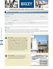
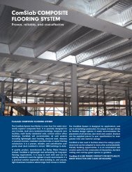
Comslab COMPOSITE FLOORING SYSTEM<br />
The ComSlab <strong>System</strong> from Bailey is a two hour fire rated, structurally<br />
superior composite floor. It is specially designed for<br />
use in hotels, multi story residential buildings, long-term care<br />
facilities, multi family residential units, schools and/or office<br />
buildings. ComSlab will accommodate all wall systems<br />
including lightweight steel framing, structural steel, masonry<br />
or poured concrete, insulated concrete forms or wood framing<br />
construction. It is a proven, reliable, and cost-effective composite<br />
steel deck installed in almost 1000 buildings to date.<br />
A quality product, manufactured by Bailey Metal Products<br />
Limited, ComSlab is lightweight and self-seating for long-span<br />
flooring requirements. It is easy to work with and can be<br />
rapidly installed in even <strong>the</strong> tightest of work environments. It is<br />
a practical solution especially when building in, and around,<br />
tight downtown locations where large truck access is limited.<br />
The ComSlab <strong>System</strong> is designed for applications and<br />
use in all building construction. It’s unique concept allows<br />
for flexible design options. It easily accommodates <strong>the</strong><br />
placement of all services, duct work and conduit. Sections<br />
can be supplied pre-cut to your specifications for even<br />
greater time and material savings.<br />
ComSlab is best used in facilities where fire rating is paramount<br />
and can be adapted to many o<strong>the</strong>r environmentallyfriendly<br />
building opportunities. It is an economical and<br />
creative option for <strong>the</strong> construction of mezzanines, dry-deck<br />
roofing and roof-top green spaces or gardens.<br />
ComSlab IS A LEED FRIENDLY PRODUCT FOR RECYCLABILITY,<br />
WASTE REDUCTION AND CLEAN AIR BUILDING.
TABLE OF CONTENTS<br />
Introduction .............................................................................................................................................................................................. 2<br />
Benefits ...................................................................................................................................................................................................... 4<br />
Design Criteria and Technical Data.................................................................................................................................................. 5<br />
Steel Deck Cross Section Properties ................................................................................................................................................ 5<br />
Live Load Calculations.......................................................................................................................................................................... 7<br />
Deflection Due to Slab Weight .......................................................................................................................................................... 7<br />
Specifications .......................................................................................................................................................................................... 8<br />
References Documents .......................................................................................................................................................................... 9<br />
SI - Metric to Imperial Conversions .................................................................................................................................................... 9<br />
Construction and Installation Guidelines ...................................................................................................................................... 10<br />
Dry Deck.................................................................................................................................................................................................. 12<br />
Examples of Construction Applications.......................................................................................................................................... 14<br />
Fire Ratings and Sound Rating ........................................................................................................................................................ 17<br />
Concrete Volume Values for Estimating ........................................................................................................................................ 17<br />
Reinforcing Bar Information .............................................................................................................................................................. 17<br />
Round Service Hole Details .............................................................................................................................................................. 18<br />
Maximum Round Service Hole Diameters .................................................................................................................................... 18<br />
Steel Deck and Accessories .............................................................................................................................................................. 19<br />
Composite Slab Load Tables, Imperial Units .............................................................................................................................. 20<br />
0.036 in. Deck - 10 mm Nominal Rebar .......................................................................................................................................... 20<br />
0.036 in. Deck - 15 mm Nominal Rebar............................................................................................................................................ 21<br />
0.036 in. Deck - 20 mm Nominal Rebar .......................................................................................................................................... 22<br />
0.036 in. Deck - 25 mm Nominal Rebar .......................................................................................................................................... 23<br />
0.036 in. Deck - 30 mm Nominal Rebar .......................................................................................................................................... 24<br />
0.036 in. Deck - 35 mm Nominal Rebar .......................................................................................................................................... 25<br />
0.048 in. Deck - 10 mm Nominal Rebar .......................................................................................................................................... 26<br />
0.048 in. Deck - 15 mm Nominal Rebar .......................................................................................................................................... 27<br />
0.048 in. Deck - 20 mm Nominal Rebar .......................................................................................................................................... 28<br />
0.048 in. Deck - 25 mm Nominal Rebar .......................................................................................................................................... 29<br />
0.048 in. Deck - 30 mm Nominal Rebar .......................................................................................................................................... 30<br />
0.048 in. Deck - 35 mm Nominal Rebar .......................................................................................................................................... 31<br />
Composite Slab Load Tables, SI Metric Units.............................................................................................................................. 32<br />
0.914 mm Deck - 10 mm Nominal Rebar .......................................................................................................................................... 32<br />
0.914 mm Deck - 15 mm Nominal Rebar .......................................................................................................................................... 33<br />
0.914 mm Deck - 20 mm Nominal Rebar .......................................................................................................................................... 34<br />
0.914 mm Deck - 25 mm Nominal Rebar .......................................................................................................................................... 35<br />
0.914 mm Deck - 30 mm Nominal Rebar .......................................................................................................................................... 36<br />
0.914 mm Deck - 35 mm Nominal Rebar .......................................................................................................................................... 37<br />
1.22 mm Deck - 10 mm Nominal Rebar .......................................................................................................................................... 38<br />
1.22 mm Deck - 15 mm Nominal Rebar .......................................................................................................................................... 39<br />
1.22 mm Deck - 20 mm Nominal Rebar .......................................................................................................................................... 40<br />
1.22 mm Deck - 25 mm Nominal Rebar .......................................................................................................................................... 41<br />
1.22 mm Deck - 30 mm Nominal Rebar .......................................................................................................................................... 42<br />
1.22 mm Deck - 35 mm Nominal Rebar .......................................................................................................................................... 43<br />
www.bmp-group.com<br />
3
ComSlab COMPOSITE FLOOR SYSTEM<br />
WHY CHOOSE ComSlab FOR YOUR NEXT FLOORING PROJECT?<br />
• Cost-effective<br />
• Unique benefits not found in pre-cast or cast<br />
in place reinforced concrete construction<br />
• All services are easily accommodated by <strong>the</strong><br />
ComSlab design profile<br />
• Easy to work with and adaptable to all wall systems<br />
• Two Hour Fire Rating – Best in <strong>the</strong> industry!<br />
• Designed for long span construction of up to 36 ft<br />
• Ideal for fast-track construction especially in tight<br />
working spaces<br />
ComSlab BENEFITS<br />
www.bmp-group.com<br />
Rigid Steel Deck<br />
Provides safe unshored work platform<br />
Multi Span<br />
Meets a wide range of architectural designs<br />
4<br />
Sound Transmission Class<br />
Meets and exceeds building code requirements<br />
Long Clear Span<br />
Up to 36 feet, depth as shallow as 10.5 inches<br />
Fast Track Construction<br />
Accommodates duct work, conduit and o<strong>the</strong>r building services<br />
Design Flexibility for 45° Assembly<br />
Lightweight interlock design for rapid installation
DESIGN CRITERIA AND TECHNICAL DATA<br />
This catalogue provides technical and structural information for <strong>the</strong> ComSlab composite concrete slab system. All calculations,<br />
whenever applicable, were based on CSA Standard S136 and CSSBI documents. Design load tables are also presented, as well<br />
as various construction applications to assist <strong>the</strong> designer in detailing common structural assemblies. Additional assistance regarding<br />
<strong>the</strong> ComSlab Composite Flooring <strong>System</strong> construction method may be obtained by contacting <strong>the</strong> Bailey Metal Products sales<br />
office in your area.<br />
The structural load tables and technical information contained in this catalogue were prepared by Dr. R.M. Schuster, P.Eng.,<br />
Professor Emeritus of Structural Engineering at <strong>the</strong> University of Waterloo.<br />
ComSlab CROSS SECTION PROPERTIES<br />
185 mm<br />
425 mm 185 mm<br />
72.5º<br />
203 mm<br />
56 mm 92.5 mm<br />
Side-lap<br />
Washer<br />
www.bmp-group.com<br />
LC<br />
Cover width 610 mm<br />
CL<br />
5<br />
IMPERIAL UNITS<br />
Base Steel<br />
Thickness<br />
(in.)<br />
SI - UNITS<br />
Base Steel<br />
Thickness<br />
mm<br />
Profile<br />
Depth<br />
(in.)<br />
Profile<br />
Depth<br />
mm<br />
Profile<br />
Weight<br />
(psf)<br />
Ag 1<br />
(in. 2 /ft)<br />
0.0360 8.00 2.46 0.698 0.281 0.615 3.35<br />
0.0480 8.00 3.26 0.931 0.424 0.994 5.42<br />
Profile<br />
Mass<br />
kg/m 2 Ag 1<br />
mm 2 /m<br />
0.914 203 12.0 1477 591 33.0 4.56<br />
1.22 203 15.9 1969 893 53.3 7.38<br />
Ae 2<br />
(in. 2 /ft)<br />
Ae 2<br />
mm 2 /m<br />
Sp 3<br />
(in. 3 /ft)<br />
Sp 3<br />
10 3 mm 3 /m<br />
Ix 4<br />
(in. 4 /ft)<br />
Ix 4<br />
10 6 mm 4 /m<br />
TABLE NOTES<br />
1<br />
Ag = Gross cross sectional area of profile per unit width.<br />
2<br />
Ae = Effective cross sectional area of profile per unit width.<br />
3<br />
Sp = Effective section modulus of profile per unit width for positive bending.<br />
4<br />
Ix = Effective moment of inertia of profile per unit width.
DESIGN CRITERIA AND TECHNICAL DATA<br />
DESIGN CRITERIA<br />
www.bmp-group.com<br />
6<br />
MATERIALS<br />
• Steel deck meets <strong>the</strong> requirements of ASTM A653 Standard<br />
Specification of Steel Sheet, Zinc-coated (Galvanized) by <strong>the</strong> Hotdip<br />
Process, Structural (Physical) Quality. Guaranteed minimum<br />
yield <strong>strength</strong> is 345 MPa (50 ksi) with a minimum zinc coating<br />
mass of 275 g/m 2 Z 275 (G90) total both sides. Steel deck base<br />
thickness is 0.914 mm (0.036 in.) or 1.22 mm (0.048 in.).<br />
• Reinforcing steel meets <strong>the</strong> requirements of CSA G30.18-09.<br />
Guaranteed minimum yield <strong>strength</strong> is 400 MPa (58.0 ksi). The<br />
clear distance of each reinforcing bar from <strong>the</strong> bottom of <strong>the</strong><br />
steel deck is 40 mm (1.57 in.).<br />
• Concrete is assumed to have a minimum cylinder <strong>strength</strong> of 30<br />
MPa (4.35 ksi) with a maximum aggregate size of 20 mm (0.75<br />
in.). Normal density structural concrete is 2400 kg/m 3 (150 lb/ft 3 ).<br />
LIMIT STATES DESIGN (LSD)<br />
• Strength – Limit states design principles were used in <strong>the</strong> development<br />
of <strong>the</strong> structural load tables, i.e., <strong>the</strong> factored resistance<br />
under consideration, φR ≥ <strong>the</strong> effect of <strong>the</strong> factored loads. This<br />
is in accordance with <strong>the</strong> National Building Code of Canada,<br />
2005. Since <strong>the</strong> self weight of <strong>the</strong> steel deck and <strong>the</strong> concrete<br />
have already been included in <strong>the</strong> structural load tables, <strong>the</strong><br />
maximum specified load (from <strong>the</strong> appropriate structural table)<br />
shall be: > (LL + 1.25/1.5DL), where<br />
LL - Specified live load<br />
DL - Specified superimposed dead load<br />
1.25 - Dead load factor<br />
1.5 - Live load factor<br />
• Serviceability – If deflection controls, <strong>the</strong> maximum specified<br />
load (from <strong>the</strong> appropriate structural table) shall be: ≥ (LL + DL).<br />
SECTION PROPERTIES OF STEEL DECK<br />
All structural section properties of <strong>the</strong> steel deck were calculated in<br />
accordance with CSA Standard S136-07. See page 5 for section<br />
properties and cross section details.<br />
STRUCTURAL LOAD TABLES<br />
The structural load tables provide maximum specified loads and<br />
were established in accordance with CSSBI 12M-2008 and CSSBI<br />
S3-2008.<br />
• Shoring During Construction<br />
Shoring requirements for <strong>the</strong> steel deck during construction were<br />
established in accordance with CSSBI 12M-2008. The following<br />
<strong>strength</strong> and deflection criteria were used:<br />
• Strength – Calculations were based on <strong>the</strong> combined loads due<br />
to <strong>the</strong> wet concrete, <strong>the</strong> steel deck and certain construction live<br />
loads. The minimum construction live loads applied separately are:<br />
1) 1 kPa (21 psf) uniform load.<br />
2) 2 kN/m (137 lb/ft) transverse line load<br />
at <strong>the</strong> centre of <strong>the</strong> span.<br />
• Serviceability – Calculated deflections were based on <strong>the</strong><br />
uniform load of concrete slab and steel deck and <strong>the</strong> maximum<br />
deflections were limited to L/180 or 20 mm (0.787 in.).<br />
Presented in <strong>the</strong> ComSlab composite slab load tables are two<br />
maximum unshored span conditions, i.e.,<br />
1) Maximum Unshored Span – based on <strong>the</strong> above stated<br />
<strong>strength</strong> and serviceability criteria.<br />
2) Maximum Unshored Span – based on <strong>the</strong> above stated<br />
<strong>strength</strong> and serviceability criteria, except a 2 kPa (42 psf)<br />
uniform load was used instead of 1 kPa (21 psf). This was<br />
done because in some jurisdictions a 2 kPa (42 psf) uniform<br />
live load is required.<br />
At <strong>the</strong> top of each structural load table, two maximum<br />
unshored span conditions are given. Using this information,<br />
one can determine <strong>the</strong> number of shores required<br />
for any given span condition.<br />
• Load Tables – Both <strong>strength</strong> and deflection criteria were<br />
considered in accordance with CSSBI S3-2008, as follows.<br />
• Strength – Flexure was <strong>the</strong> only criteria considered in <strong>the</strong><br />
calculations since shear-bond is not a mode of failure. In<br />
accordance with Table 4.1.5.10 of <strong>the</strong> National Building Code<br />
of Canada, 2005, a 9 kN (2023 lb) specified concentrated live<br />
load was included in <strong>the</strong> <strong>strength</strong> calculations.<br />
• Serviceability – Calculated deflections due to specified<br />
superimposed loads (LL + DL) were based on a uniform load<br />
with <strong>the</strong> maximum deflection limited to L/360. The modular ratio<br />
for normal density concrete was taken as 10 and <strong>the</strong> moment of<br />
inertia is <strong>the</strong> average of <strong>the</strong> uncracked and cracked moment of<br />
inertias. For use of <strong>the</strong> deflection parameter, SLDP, see example<br />
on page 7. To determine <strong>the</strong> deflection due to <strong>the</strong> slab weight,<br />
also see page 7.<br />
• Use of Load Tables – See example on page 7 for use of<br />
structural load tables.<br />
STRUCTURAL TESTING<br />
Structural ComSlab composite slab tests were carried out at <strong>the</strong><br />
University of Salford, England by Prof. D. O’Leary (April, 1993).<br />
Based on <strong>the</strong>se tests, shear-bond was not a mode of failure.<br />
Typically, composite slab systems fail in shear-bond. However, since<br />
<strong>the</strong> ComSlab composite slab system also has reinforcing steel,<br />
shear-bond is not a governing failure mode.
DESIGN CRITERIA AND TECHNICAL DATA<br />
ComSlab EXAMPLE (IMPERIAL UNITS)<br />
Given <strong>the</strong> following information, check <strong>the</strong> adequacy of <strong>the</strong> ComSlab floor system:<br />
Given:<br />
Steel deck - Design thickness = 0.036 in.; yield <strong>strength</strong> = 50 ksi<br />
Reinforcing steel - Bar diameter = 25 mm; yield <strong>strength</strong> = 58 ksi<br />
Concrete - Normal density = 150 lb/ft 2<br />
Overall slab depth = 10.5 in.<br />
Single span length = 24 ft<br />
Specified Loads<br />
Superimposed dead load<br />
a) floor finish = 10.5 psf<br />
b) partitions = 20.0 psf<br />
DL = 30.5 psf<br />
Live load LL = 100 psf<br />
Total load = {1.25/1.5(DL) + LL} = {0.833(30.5) + 100} = 125 psf<br />
Use of load table:<br />
From <strong>the</strong> appropriate table (page 24), <strong>the</strong> maximum specified load is 133 psf,<br />
which is controlled by deflection and is checked as follows:<br />
(DL + LL) = (30.5 + 100) = 131 psf<br />
Since 133 > 131 OK<br />
NOTE: One shore support is required at mid-span.<br />
USE OF DEFLECTION PARAMETER<br />
www.bmp-group.com<br />
Imperial Units<br />
w d =<br />
Where:<br />
wd = Maximum specified deflection load in kPa or psf,<br />
DP = Deflection parameter from load table,<br />
DC = Deflection constant such as 360,<br />
L = Span length in metres or feet<br />
Examples:<br />
DP x 10 6<br />
DC x (L) 3<br />
SI-Units<br />
w d =<br />
DP x 103<br />
DC x (L) 3<br />
Base steel thickness – 0.914 mm<br />
Base steel thickness – 0.036 in.<br />
Nominal bar diameter – 30 mm<br />
Nominal bar diameter – 25 mm<br />
Slab depth – 260 mm<br />
Slab depth – 10.5 in.<br />
Span length, L, – 8 m<br />
Span length, L – 25 ft<br />
From table on page 36, DP = 913 From table on page 23, DP = 663<br />
Assume DC = 360 Assume DC = 400<br />
w d =<br />
913 x 103<br />
360 x (8) 3 = 4.95 kPa w d =<br />
663 x 106<br />
400 x (25) 3 = 106 psf<br />
For DC = 360, w d = 118 psf<br />
DEFLECTION DUE TO SLAB WEIGHT<br />
The deflection due to <strong>the</strong> slab weight<br />
can be calculated as follows. The<br />
calculation is based on <strong>the</strong> uncracked<br />
moment of inertia of <strong>the</strong> section and<br />
<strong>the</strong> deflection parameter, SWDP, can<br />
be obtained from <strong>the</strong> load tables.<br />
Imperial Units<br />
SWDP x (L)4<br />
δsw =<br />
= in.<br />
10 6<br />
L = feet<br />
SI-Units<br />
SWDP x (L)4<br />
δsw =<br />
= mm<br />
10 3<br />
L = metres<br />
7<br />
NOTE: For confirmation of values, see appropriate load tables.
ComSlab SPECIFICATIONS<br />
www.bmp-group.com<br />
8<br />
1.1 SCOPE<br />
These Specifications cover <strong>the</strong> design, manufacture and use of <strong>the</strong><br />
ComSlab composite floor system.<br />
• Furnish all materials and services for <strong>the</strong> fabrication of <strong>the</strong><br />
ComSlab composite floor system in accordance with <strong>the</strong>se<br />
Specifications and applicable drawings. ComSlab composite<br />
floor systems shall be manufactured and marketed by Bailey<br />
Metal Products.<br />
• Fully co-ordinate <strong>the</strong> ComSlab composite floor system with<br />
structural, mechanical, electrical and architectural components<br />
of <strong>the</strong> building.<br />
1.2 CODE & STANDARD<br />
• Design and manufacturing shall be in strict accordance with <strong>the</strong><br />
ComSlab composite floor systems, BMP, using steel conforming<br />
to <strong>the</strong> requirements of ASTM A653, Standard Specification for<br />
Steel Sheet, Zinc-coated (Galvanized) by <strong>the</strong> Hot Dip Process and<br />
Having Structural Physical Quality. Guaranteed minimum yield<br />
<strong>strength</strong> shall be 345 MPa (50 ksi) with a minimum zinc coating<br />
mass of 275 g/m 2 Z 275 (G90) total including both sides. Steel<br />
deck base thickness shall be ei<strong>the</strong>r 0.914 mm (0.036 in.) or 1.22<br />
mm (0.048 in.).<br />
• Reinforcing steel shall meet <strong>the</strong> requirements of CSA G 30.18-09.<br />
Guaranteed minimum yield <strong>strength</strong> shall be 400 MPa (58 ksi).<br />
The clear distance of each reinforcing bar from <strong>the</strong> bottom of <strong>the</strong><br />
steel deck shall be 40 mm (1.57 in.).<br />
• Concrete shall have a minimum cylinder <strong>strength</strong> of 30 MPa (4.35<br />
ksi) with a maximum aggregate size of 20 mm (0.75 in.). Normal<br />
density structural concrete used shall be 2400 kg/m 3 (150 lb/ft 3 ).<br />
1.3 DESIGN<br />
• Strength – Flexural design shall be by limit states design principles<br />
which were used in <strong>the</strong> development of <strong>the</strong> structural load tables:<br />
• The factored resistance under consideration, φR ≥ <strong>the</strong> effect of<br />
<strong>the</strong> factored loads. This is in accordance with <strong>the</strong> National<br />
Building Code of Canada 2005.<br />
• Since <strong>the</strong> self-weight of <strong>the</strong> steel deck, <strong>the</strong> reinforcing bar and <strong>the</strong><br />
concrete have been included in <strong>the</strong> structural load tables, <strong>the</strong><br />
maximum specified load (from <strong>the</strong> appropriate structural load<br />
table) shall be: (LL + 1.25/1.5DL),<br />
where:<br />
LL - Specified live load<br />
DL - Specified superimposed dead load<br />
1.25 - Dead load factor<br />
1.5 - Live load factor<br />
• Serviceability – If deflection controls, <strong>the</strong> maximum specified<br />
load (from <strong>the</strong> appropriate structural load table) shall be:<br />
(LL + DL).<br />
1.4 SHOP DRAWINGS<br />
• Detailed erection drawings shall be submitted by <strong>the</strong> purchaser<br />
to <strong>the</strong> Architect, Engineer, General Contractor or representative<br />
for approval, showing material lists, mark numbers, types,<br />
locations, spacing of floor pans and accessories showing<br />
method of attachment to supporting members. Contract drawing<br />
notes relative to <strong>the</strong> ComSlab composite floor system shall be<br />
considered a part of this Specification as though fully set forth<br />
herein.<br />
• Shop drawings, prepared only from approved erection drawings,<br />
shall be used for fabrication and erection.<br />
• Figured dimensions only shall be used. Scaling drawings shall<br />
NOT be permitted.<br />
1.5 HANDLING & STORAGE<br />
• Care shall be exercised at all times to avoid damage to<br />
ComSlab composite floor system components during loading,<br />
storing and erecting. Damaged decking must be replaced.<br />
• ComSlab deck panels are supplied in bundles of up to 30<br />
sheets. Each bundle can weigh up to 2.5 tonnes (5500 lb).<br />
Individual decking elements can twist when lifted so care shall<br />
be taken when lifting with slings or forks.<br />
• ComSlab deck panels shall be stored on timber supports,<br />
clear of <strong>the</strong> ground. The bundles are marked and shall be<br />
positioned on and/or in <strong>the</strong> area indicated on <strong>the</strong> layout<br />
drawings. The bundles shall be placed with <strong>the</strong> pre-punched<br />
holes in <strong>the</strong> lap on <strong>the</strong> same side, unless o<strong>the</strong>rwise noted on<br />
<strong>the</strong> layout drawings.<br />
1.6 PRODUCTS<br />
• ComSlab steel deck panels are fabricated using Z275 (G90)<br />
galvanized steel sheet, of ei<strong>the</strong>r 0.914 mm (0.036 in.) or 1.22mm<br />
(0.048 in.) in thickness.<br />
• End Closures are fabricated using Z275 (G90) galvanized steel<br />
sheet, 1.52 mm (0.060 in.) in thickness.<br />
• Perimeter Trims are fabricated using Z275 (G90) galvanized<br />
steel sheet, 1.52 mm (0.060 in.) in thickness.<br />
• Inside Trims are fabricated using Z180 (G60) galvanized steel<br />
sheet of ei<strong>the</strong>r 0.914 mm (0.036 in.) or 1.22 mm (0.048 in.) in<br />
thickness, depending on <strong>the</strong> ComSlab steel deck thickness.<br />
• Corridor Trims are fabricated using Z180 (G60) galvanized steel<br />
sheet, 1.52 mm (0.060 in.) in thickness.<br />
• Side-lap Washers are fabricated using Z180 (G60) galvanized<br />
steel sheet, 1.22 mm (0.048 in.) in thickness.<br />
• Rebar Supports are fabricated using Z180 (G60) galvanized<br />
steel sheet, 0.914 mm (0.036 in.) in thickness.<br />
• Restraint Straps are fabricated using Z180 (G60) galvanized<br />
steel sheet, minimum 0.838 mm (0.033 in.) in thickness.
ComSlab SPECIFICATIONS<br />
1.7 EXECUTION<br />
• Installation shall be in accordance with <strong>the</strong> latest Construction<br />
Guidelines for <strong>the</strong> ComSlab composite floor system. Care shall<br />
be exercised to avoid damage through careless handling during<br />
unloading, storing and erecting. Suitably qualified personnel<br />
shall install ComSlab floor components.<br />
• End Closures shall be fixed to <strong>the</strong> support structure prior to <strong>the</strong><br />
decking being installed, using a minimum of 2 fasteners (such as<br />
shot-fired pins or self-drilling fasteners, and using <strong>the</strong> following<br />
fastener Specifications or equivalency:<br />
In addition to <strong>the</strong> main structural fastening, <strong>the</strong> profile top<br />
flanges are fixed to <strong>the</strong> upper flange of <strong>the</strong> End Closures using<br />
self-drilling fasteners at a frequency of 1 fastener per profile.<br />
The following fastener Specification shall be used:<br />
No. 12 x 25.4 mm (1 in.) or better, hexagon washer head, zinc<br />
coated or equivalent. The above fasteners shall be installed<br />
using a correctly set screw gun to <strong>the</strong> data available from <strong>the</strong><br />
fastener supplier.<br />
• Ensure that current decking drawings are being used. The<br />
ComSlab deck panels shall be correctly fastened at each end to<br />
<strong>the</strong> bearing wall substrate with appropriate mechanical<br />
fasteners. The ComSlab deck panels shall bear a minimum of 50<br />
mm (2 in.) onto <strong>the</strong> support structure.<br />
• Perimeter Trims shall be fastened to <strong>the</strong> wall substrate in a true<br />
and plumb manner, using <strong>the</strong> appropriate fastener to suit <strong>the</strong><br />
steel or concrete substrate at 350 mm (13.8 in.) intervals in<br />
accordance with <strong>the</strong> data available from <strong>the</strong> fastener supplier.<br />
• Interior deck panel closures shall be fastened to <strong>the</strong> ComSlab<br />
deck panel with a minimum of 50 mm (2 in.) overlap, fastened<br />
toge<strong>the</strong>r with No. 12 x 25.4 mm (1 in.) or better, hexagon washer<br />
head self-drilling screws spaced at 350 mm (13.8 in.) on centre.<br />
Panel closures shall be <strong>the</strong> equivalent thickness of <strong>the</strong> ComSlab<br />
deck panel specified. Alternately, <strong>the</strong> ComSlab panel can be cut<br />
longitudinally and overlapped a minimum of 75 mm (3 in.) and<br />
fastened toge<strong>the</strong>r at 300 mm (12 in.) on centre with 2 fasteners<br />
paired 25.4 mm (1 in.) apart.<br />
• Side-lap Washers shall be installed at 350 mm (13.8 in.) along<br />
<strong>the</strong> bottom trough of each vault profile using No. 12 x 25.4 mm<br />
(1 in.) or better, hexagon washer head self-drilling screws. The<br />
fastener location is indicated by pre-punched holes in <strong>the</strong> male<br />
overlap. The laps shall be correctly connected toge<strong>the</strong>r as <strong>the</strong>y<br />
form a critical part of <strong>the</strong> flooring system.<br />
• Rebar Supports shall be installed at 1220 mm (4 ft) on centre<br />
maximum, to support <strong>the</strong> reinforcing bars (10 mm to 35 mm, as<br />
specified) in each vault or trough in accordance with Section 1.2<br />
of <strong>the</strong>se Specifications – 40 mm (1.57 in.) clearance.<br />
• Restraint Straps shall be installed 400 mm (16 in.) on centre, one<br />
end to <strong>the</strong> Perimeter Trim return flange and <strong>the</strong> o<strong>the</strong>r end to <strong>the</strong><br />
top of <strong>the</strong> deck panel for concrete pressure restraint during <strong>the</strong><br />
concrete placement phase of construction.<br />
• Shoring shall be supplied and installed by qualified personnel at<br />
<strong>the</strong> locations specified on <strong>the</strong> drawings. If in doubt, check with<br />
<strong>the</strong> supplier’s technical department and <strong>the</strong> engineer of record.<br />
Shoring shall not be removed until <strong>the</strong> concrete has reached 75%<br />
of its required design <strong>strength</strong>, or as authorized by <strong>the</strong> engineer<br />
of record. Consult with <strong>the</strong> engineer of record to be sure that <strong>the</strong><br />
shoring meets <strong>the</strong> local jurisdictional requirements before<br />
placing of concrete.<br />
• Concrete shall be placed in accordance with CAN CSA A23.1-09.<br />
Good concrete placement practices shall be carried out at all<br />
times. Refer to concrete practice guidelines before starting<br />
concrete placement.<br />
1.8 REFERENCE DOCUMENTS<br />
• CSA S136-07, “North American Specification for <strong>the</strong> Design of Cold-Formed Steel<br />
Structural Members”, Canadian Standards Association, Mississauga, Ontario,<br />
October 2007.<br />
• CSSBI S2-2008, “Criteria for <strong>the</strong> Testing of Composite Slabs”, Canadian Sheet<br />
Steel Building Institute, Cambridge, Ontario, October 2008.<br />
• CSSBI 12M-2008, “Standard for Composite Steel Deck”, Canadian Sheet Steel<br />
Building Institute, Cambridge, Ontario, October 2008.<br />
• CSSBI S3-2008, “Criteria for <strong>the</strong> Design of Composite Slabs”, Canadian Sheet<br />
Steel Building Institute, Cambridge, Ontario, October 2008.<br />
• CSA G30.18-09, “Carbon Steel Bars for Concrete Reinforcement”, Canadian<br />
Standards Association, Mississauga, Ontario, 2009.<br />
• NBC 2005, “National Building Code of Canada 2005”, Issued by <strong>the</strong> Commission<br />
on Building and Fire Codes, National Research Council of Canada, Ottawa, 2005.<br />
• CSA A23.1-09, “Concrete Materials and Methods of Concrete Construction”,<br />
Canadian Standards Association, Mississauga, Ontario, 2009.<br />
• Warnock, A.C.C “Factors Affecting Sound Transmission Loss”, Canadian Building<br />
Digest No. 239, National Research Council of Canada, Ottawa, July 1985.<br />
• “List of Equipment and Materials, Volume II, Building Materials”, Underwriters’<br />
Laboratories of Canada, Scarborough, Ontario Canada, 1998.<br />
• “Fire Resistance Directory, Volume 1, 1999”, Underwriters Laboratories Inc.,<br />
Northbrook, Illinois.<br />
1.9 SI-METRIC TO IMPERIAL CONVERSIONS<br />
Listed below are some common conversion factors to assist users<br />
with <strong>the</strong> information contained in this catalogue.<br />
From SI-Metric Units To Imperial Units Divide by<br />
mm in. 25.4<br />
mm 2 in. 2 645.2<br />
mm 3 in. 3 16 387<br />
mm 4 in. 4 416 231<br />
m ft 0.3048<br />
m 2 ft 2 0.0929<br />
kN kips 4.44822<br />
kPa (kN/m 2 ) psf 0.04788<br />
kg/m lb/ft 1.488<br />
MPa (N/mm 2 ) kips/in. 2 6.895<br />
N-m kips-in. 113<br />
www.bmp-group.com<br />
9
CONSTRUCTION AND INSTALLATION GUIDELINES<br />
DECKING INSTALLATION<br />
ComSlab PANEL DECKING – shall be positively fastened to <strong>the</strong> supporting structure to avoid movement during construction and<br />
excessive deflection during placement of concrete. The fastening frequency of main fasteners is 1 per trough at each panel end at<br />
610 mm (24 in.) on centre along <strong>the</strong> support structure. The ComSlab deck panels shall bear a minimum of 50 mm (2 in.) onto <strong>the</strong><br />
support structure. When fastening panels to structural steel work, use heavy-duty shotfired pins or self-drilling fasteners as designed and<br />
specified by <strong>the</strong> engineer of record. For brick, block and concrete, <strong>the</strong> decking shall be fastened using adequate masonry fasteners as<br />
designed and specified by <strong>the</strong> engineer of record. The bottom flange of <strong>the</strong> End Closure shall be fastened to <strong>the</strong> supporting structure with<br />
1 fastener per module at 610 mm (24 in.) on centre, or as specified by <strong>the</strong> engineer of record.<br />
In addition to <strong>the</strong> main fasteners, <strong>the</strong> top flanges of <strong>the</strong> End Closures shall be fastened to <strong>the</strong> decking, one fastener per module, ei<strong>the</strong>r<br />
centred or 610 mm (24 in.) on centre. Side-lap Washers shall be fastened at 350 mm (13.8 in.) centres along <strong>the</strong> bottom trough, using<br />
No. 14 1/4 - 14 x 1 self-drilling fasteners or better. The location of <strong>the</strong> fasteners is prepunched on <strong>the</strong> male trough flange, which overlaps<br />
<strong>the</strong> female trough flange.<br />
www.bmp-group.com<br />
10<br />
NOTE 1: Every side-lap fastener shall include a Side-lap Washer. This washer is required to properly attach <strong>the</strong> individual steel deck<br />
panels toge<strong>the</strong>r.<br />
NOTE 2: When a suspended ceiling is used, <strong>the</strong> minimum thread length of <strong>the</strong> fastener is 25 mm (1 in.).<br />
NOTE 3: ComSlab decking can be end cantilevered as shown in <strong>the</strong> “Examples of Construction Applications” section on page 14. When<br />
side cantilevers are required, stub beams or brackets shall be provided by <strong>the</strong> structural steel fabricator, as designed by <strong>the</strong> engineer<br />
of record. Cantilevers shall also be assessed for reinforcement by <strong>the</strong> engineer of record.<br />
1<br />
END CLOSURES – To minimize grout loss at <strong>the</strong> profile ends<br />
during concrete placement, End Closures are provided to<br />
contain <strong>the</strong> concrete. These closures are manufactured<br />
from 1.52 mm (0.060 in.) galvanized steel, generally 1830<br />
mm (6 ft) long or longer for angle cut installations. End<br />
Closures shall be fastened to <strong>the</strong> support structure at<br />
maximum intervals of 610 mm (24 in.), using shot-fired pins,<br />
self-drilling fasteners or as specified by <strong>the</strong> engineer of<br />
record. Apart from minimizing grout loss during concrete<br />
placement, <strong>the</strong>se End Closures provide <strong>strength</strong> to prevent<br />
web crippling of <strong>the</strong> steel deck and proper alignment of<br />
<strong>the</strong> decking during construction. When used in conjunction<br />
with hot-rolled steel beams, <strong>the</strong>se End Closures provide<br />
concrete cover to <strong>the</strong> steel beam for fire resistance.<br />
2<br />
SIDE-LAP WASHERS – Since <strong>the</strong> ComSlab deck acts in<br />
part compositely with <strong>the</strong> concrete, Side-lap Washers<br />
are important connecting elements. These washers are<br />
prepunched to receive <strong>the</strong> self-drilling fastener.
CONSTRUCTION AND INSTALLATION GUIDELINES<br />
DECKING INSTALLATION<br />
3<br />
PERIMETER TRIMS – Are required for <strong>the</strong> retention of wet concrete to <strong>the</strong> correct level<br />
at <strong>the</strong> decked floor perimeters and designed openings. They are supplied in 3 m (10<br />
ft) lengths of galvanized steel. Perimeter Trims are usually fastened by shot-fired pins<br />
to <strong>the</strong> structural steel or by self-drilling fasteners to <strong>the</strong> support structure at 610 mm (24<br />
in.) on centre, or as specified by <strong>the</strong> engineer of record.<br />
4<br />
RESTRAINT STRAPS – The top of <strong>the</strong> perimeter edge trim is connected to <strong>the</strong> decking<br />
with Restraint Straps at approximately 400 mm (16 in.) on centre using ei<strong>the</strong>r pop rivets<br />
or self-drilling fasteners. The Restraint Strap can be adjusted to suit <strong>the</strong> pitch and<br />
alignment of <strong>the</strong> perimeter edge trim.<br />
5<br />
PENETRATIONS – Penetrations through <strong>the</strong> floor decking shall be cut after <strong>the</strong> concrete<br />
has cured. Before placing concrete, any openings shall be boxed out with form work<br />
as specified by <strong>the</strong> engineer of record. The following guidelines are suggested for isolated<br />
openings at right angles to <strong>the</strong> deck span, or as specified by <strong>the</strong> engineer of record:<br />
• Up to 300 mm (12 in.) square penetrations centred on <strong>the</strong> top of <strong>the</strong> profile of <strong>the</strong><br />
deck is acceptable without additional reinforcement, o<strong>the</strong>r than <strong>the</strong> minimum<br />
shrinkage and temperature mesh.<br />
• Up to 425 mm (16.7 in.) width by 1000 mm (39.4 in.) length opening with additional<br />
reinforcement.<br />
• Openings larger than 425 mm (16.7 in.) require structural steel framing as specified<br />
by <strong>the</strong> engineer of record.<br />
• Close grouping of openings transverse to <strong>the</strong> profile shall be treated as one<br />
opening, requiring additional reinforcement as specified by <strong>the</strong> engineer of record.<br />
• After <strong>the</strong> slab has reached 75% of <strong>the</strong> required concrete compressive <strong>strength</strong>, a<br />
nibbler, power saw or coring machine can be used to cut out openings in <strong>the</strong> top<br />
profile with <strong>the</strong> approval by <strong>the</strong> engineer of record.<br />
www.bmp-group.com<br />
11<br />
6<br />
COLUMNS AND ComSlab DECKING – The steel deck sheeting can be cut and fitted<br />
to accommodate various column shapes to minimize grout loss. Where no supporting<br />
steel work is provided, steel angle brackets shall be provided to support <strong>the</strong> steel<br />
decking, as specified by <strong>the</strong> engineer of record.<br />
7<br />
RIB REINFORCEMENT AND MESH PLACEMENT – The ComSlab design requires that<br />
one steel reinforcing bar be placed in each rib profile. The bar size, as shown in <strong>the</strong><br />
load tables, can vary from 10 mm (0.394 in.) to 35 mm (1.38 in.) in diameter. The bars<br />
shall be placed on Rebar Supports which ensure a 40 mm (1.57 in.) spacing from<br />
<strong>the</strong> bottom flange to <strong>the</strong> underside of <strong>the</strong> reinforcing bars. Spacing of <strong>the</strong> Rebar<br />
Supports shall be in accordance with good practice guidelines, and not exceeding<br />
1220 mm (48 in.) on centre. To ensure both vertical and horizontal stability during<br />
concrete placement, <strong>the</strong> reinforcing bars shall be tied down periodically through <strong>the</strong><br />
Side-lap Washers with 1.21 mm (0.0476 in.) diameter tie wiring. It is recommended<br />
that a minimum standard shrinkage and temperature reinforcing mesh of<br />
152x152xMW18.7xMW18.7 (6x6x6/6) be placed above <strong>the</strong> top of <strong>the</strong> steel decking<br />
and positioned towards <strong>the</strong> top of <strong>the</strong> slab, or as specified by <strong>the</strong> engineer of record.
CONSTRUCTION AND INSTALLATION GUIDELINES<br />
DECKING INSTALLATION<br />
8<br />
CONCRETE PLACEMENT – Concrete shall be placed in accordance with CSA A23.1-09.<br />
Before starting concrete placement, <strong>the</strong> steel decking shall be cleared of dirt,<br />
grease and debris, which could adversely influence <strong>the</strong> composite slab<br />
performance. Care shall be taken to avoid concrete heaping in any area during<br />
concrete placement. Typical construction live loads have been accounted for in <strong>the</strong><br />
load tables. Should additional construction loading be required, approval by <strong>the</strong><br />
engineer of record is required.<br />
www.bmp-group.com<br />
12<br />
9<br />
10<br />
TEMPORARY SUPPORTS – When <strong>the</strong> design span exceeds <strong>the</strong> maximum unshored<br />
span shown in <strong>the</strong> load tables, <strong>the</strong> wet concrete weight and construction loads shall<br />
be supported by adding temporary supports (shoring), as designed by <strong>the</strong> engineer<br />
of record. Where temporary supports are required, it is important that:<br />
• Beams and <strong>the</strong> support structure have adequate <strong>strength</strong> to support <strong>the</strong><br />
construction loads as designed and specified by <strong>the</strong> engineer of record.<br />
• Shoring is normally placed at midspan or at o<strong>the</strong>r suitable intervals, as required.<br />
• Shoring beams shall provide a minimum bearing width of 100 mm (4 in.).<br />
• The shoring structure shall remain in place until <strong>the</strong> concrete has reached 75% of<br />
its design <strong>strength</strong>, or as specified by <strong>the</strong> engineer of record.<br />
HANGER SYSTEM – The geometry of <strong>the</strong> ribs allows for <strong>the</strong> suspension of services from<br />
<strong>the</strong> profile top flange between ribs. Pre-set threaded rod hangers are easily installed<br />
before <strong>the</strong> concrete is placed. Consult your mechanical and electrical consultants, and<br />
installation contractors for accepted specifications.<br />
11<br />
SERVICE HOLES – Refer to table on page 18 for size and location of round holes<br />
through ComSlab ribs. Sleeves shall be fastened in place before concrete placement.<br />
Cut-out of holes shall be done only after <strong>the</strong> concrete has reached 75% of its design<br />
<strong>strength</strong>, or as specified by <strong>the</strong> engineer of record.<br />
12<br />
CEILING HANGER SYSTEMS – Ceilings can be suspended directly from <strong>the</strong> bottom of<br />
<strong>the</strong> steel deck.<br />
THE ComSlab DRY DECK<br />
The ComSlab system can be used as a non-composite steel deck only without concrete/rebar<br />
as a roofing solution or residential flooring system (when span/load permits). Kindly contact<br />
your BMP Technical Sales Representative for more information. Load tables with single, double<br />
and triple span conditions are available.
CONSTRUCTION AND INSTALLATION GUIDELINES<br />
END CLOSURE<br />
Install with mechanical fasteners to any lateral beam or bearing wall substrate at minimum<br />
610 mm (24 in.) on centre.<br />
PERIMETER TRIM<br />
Install Perimeter Trims for concrete containment and alignment. The top edge is<br />
used as a screed guide to achieve <strong>the</strong> overall required concrete slab depth.<br />
PLACING OF ComSlab DECK<br />
Install <strong>the</strong> deck progressively (male to female flange overlap) and fasten at<br />
350 mm (13.8 in.) on centre with Side-lap Washers and self-drilling fasteners.<br />
TEMPORARY SHORING<br />
Install in accordance with load tables based on maximum unshored span condition.<br />
The engineer of record shall approve shoring requirement and installation.<br />
www.bmp-group.com<br />
IN-FLOOR RADIANT HEATING<br />
13<br />
Install flat sheets of wire mesh or o<strong>the</strong>r equivalent material,<br />
i.e. 10 mm reinforcing bar @ 560 mm (22 in.) on centre commonly used.<br />
PLACEMENT OF CONCRETE<br />
Place concrete uniformly and screed to top of perimeter trims and avoid concrete<br />
heaping. Cylinder <strong>strength</strong> shall not be less than 30 MPa (4.35 ksi), with a maximum<br />
aggregate size of 20 mm (0.75 in.).<br />
UNDERSIDE VIEW<br />
The installed ribbed ceiling provides suitable substrate for direct finishing; applying<br />
additional fire safety protection; enhanced acoustical treatment and finishing with a<br />
variety of finished ceiling materials.
CONSTRUCTION AND INSTALLATION GUIDELINES<br />
EXAMPLES OF CONSTRUCTION APPLICATIONS<br />
Shrinkage and<br />
temperature<br />
reinforcement<br />
Concrete slab<br />
Beam reinforcing by<br />
engineer of record<br />
Perimeter Trim Concrete slab<br />
Shrinkage and<br />
temperature<br />
reinforcement<br />
COMFLOR ComSlab Deck ®<br />
deck<br />
57 mm (min.)<br />
Restraint Strap<br />
57 mm (min.)<br />
Rebar Supports<br />
with rebar at<br />
610 mm o.c.<br />
203 mm<br />
203 mm<br />
40 mm<br />
End Closure<br />
40 mm<br />
Side-lap Washers<br />
fastened at 350 mm o.c.<br />
Deck and edge trim<br />
fastened to steelwork<br />
COMFLOR ComSlab ® Deck deck<br />
www.bmp-group.com<br />
End Closure<br />
END CLOSURE DETAIL<br />
Beam reinforcing by<br />
engineer of record<br />
Perimeter Trim<br />
Shrinkage and<br />
temperature<br />
reinforcement<br />
Restraint Straps<br />
57 mm (min.)<br />
203 mm<br />
Temporary shoring<br />
Refer to load tables<br />
for span limitations<br />
Loadbearing BMP steel stud<br />
wall or structural support<br />
Beam reinforcing by<br />
engineer of record<br />
Perimeter Trim<br />
Restraint Strap<br />
SHORING DETAIL<br />
Shrinkage and<br />
temperature<br />
reinforcement<br />
57 mm (min.)<br />
Rebar Supports<br />
with rebar at<br />
610 mm o.c.<br />
203 mm<br />
14<br />
40 mm<br />
End Closure<br />
®<br />
COMFLOR ComSlab Deck deck<br />
Deck and edge trim<br />
fastened to steelwork<br />
Loadbearing BMP steel stud<br />
Rib reinforcing at wall or structural support<br />
610 mm o.c.<br />
END BEARING DETAIL<br />
COMFLOR ComSlab Deck ®<br />
deck<br />
40 mm<br />
Deck and edge trim<br />
Side-lap Washers<br />
fastened to steelwork<br />
fastened at<br />
350 mm o.c.<br />
Loadbearing BMP steel stud<br />
wall or structural support<br />
PERIMETER BEARING DETAIL<br />
Beam reinforcing by<br />
engineer of record<br />
Top flange of deck fastened to top<br />
of end closure using 1 self-drilling<br />
fastener per pitch (typical)<br />
Rib reinforcing as<br />
specified by design<br />
Concrete slab<br />
Shrinkage and<br />
temperature<br />
reinforcement<br />
57 mm (min.)<br />
Wide flange beam (WF)<br />
Rib reinforcing as<br />
specified by design<br />
Shrinkage and<br />
temperature<br />
reinforcement<br />
57 mm (min.)<br />
203 mm<br />
203 mm<br />
End Closure<br />
40 mm<br />
COMFLOR ComSlab Deck ®<br />
deck<br />
Deck and End Closures<br />
fastened to bearing using<br />
heavy-duty shot-fired pins or<br />
self-drilling fasteners (typical)<br />
®<br />
COMFLOR ComSlab Deck deck<br />
40 mm<br />
End Closure<br />
Deck and End Closures<br />
fastened to bearing using<br />
heavy-duty shot-fired pins or<br />
self-drilling fasteners (typical)<br />
Loadbearing BMP steel stud<br />
wall or structural support<br />
WALL CONNECTION DETAIL<br />
6 mm steel plate<br />
welded to WF beam<br />
WIDE FLANGE BEAM DETAIL<br />
NOTE: The following examples of construction applications for ComSlab are illustrative only and should only be used with <strong>the</strong> final approval of <strong>the</strong> engineer of record.
CONSTRUCTION AND INSTALLATION GUIDELINES<br />
EXAMPLES OF CONSTRUCTION APPLICATIONS<br />
Shrinkage and<br />
temperature<br />
reinforcement<br />
Beam reinforcing by<br />
engineer of record<br />
Shrinkage and<br />
temperature<br />
reinforcement<br />
Beam reinforcing by<br />
engineer of record<br />
Perimeter Trim<br />
Restraint Strap<br />
57 mm (min.)<br />
57 mm (min.)<br />
102 mm max.<br />
203 mm<br />
COMFLOR ComSlab ® Deck deck<br />
203 mm<br />
COMFLOR ComSlab ® Deck deck<br />
cut to suit dimensions<br />
40 mm<br />
Rib reinforcing as<br />
End Closure<br />
specified by design<br />
Deck and End Closures<br />
fastened to bearing using<br />
heavy-duty shot-fired pins or<br />
self-drilling fasteners (typical)<br />
Loadbearing BMP steel stud<br />
wall or structural support<br />
PANEL DIRECTION CHANGE DETAIL<br />
Perimeter Trim<br />
Shrinkage and<br />
temperature<br />
Restraint Strap<br />
reinforcement<br />
End Closure<br />
Refer to structural drawings for<br />
reinforcing in cantilever slab<br />
COMFLOR ComSlab ® Deck deck<br />
End Closure<br />
Rib reinforcing as<br />
specified by design<br />
Temporary shoring<br />
as required by<br />
engineer of record<br />
Cantilever slab varies,<br />
see structural drawings<br />
Loadbearing BMP steel stud<br />
wall or structural support<br />
END CANTILEVER DETAIL<br />
Inside Trim<br />
40 mm<br />
Rib reinforcing with<br />
Side-lap Washer<br />
Rebar Supports<br />
fastened at<br />
350 mm o.c.<br />
Loadbearing BMP steel stud<br />
wall or structural support<br />
SIDE PERIMETER BEARING DETAIL<br />
Corridor deck (by o<strong>the</strong>rs)<br />
Shrinkage and<br />
temperature<br />
reinforcement<br />
Beam reinforcing and<br />
stirrups, as required by<br />
engineer of record<br />
38 mm<br />
87 mm (min.)<br />
57 mm (min.)<br />
Angle<br />
203 mm<br />
135 mm clearance<br />
40 mm<br />
to top of wall<br />
COMFLOR ComSlab ® Deck deck<br />
Rib reinforcing as<br />
specified by design<br />
End Closure<br />
Deck and End Closures<br />
Loadbearing BMP steel stud<br />
fastened to support using<br />
wall or structural support<br />
heavy-duty shot-fired pins or<br />
self-drilling fasteners (typical)<br />
CORRIDOR BEARING DETAIL<br />
www.bmp-group.com<br />
15<br />
Corridor deck (by o<strong>the</strong>rs)<br />
Corridor Trim<br />
Shrinkage and<br />
temperature<br />
reinforcement<br />
End Closure<br />
Perimeter Trim<br />
Restraint Strap<br />
Shrinkage and<br />
temperature<br />
reinforcement<br />
Beam reinforcing and<br />
stirrups, as required by<br />
engineer of record<br />
®<br />
COMFLOR ComSlab Deck deck<br />
38 mm<br />
57 mm (min.)<br />
87 mm (min.)<br />
203 mm<br />
Furring channel<br />
40 mm<br />
135 mm clearance<br />
to top of wall<br />
Furring channel<br />
COMFLOR ComSlab ® Deck deck<br />
End Closure<br />
Interior finish<br />
Tie-wire as required<br />
for suspended ceiling<br />
Loadbearing BMP steel stud<br />
wall or structural support<br />
Corridor finish<br />
Loadbearing BMP steel stud<br />
wall with insulation<br />
Exterior sheathing and/or insulation<br />
(as required). See architectural drawings<br />
CORRIDOR FINISHING DETAIL<br />
END BEARING FINISHING DETAIL<br />
NOTE: The following examples of construction applications for ComSlab are illustrative only and should only be used with <strong>the</strong> final approval of <strong>the</strong> engineer of record.
CONSTRUCTION AND INSTALLATION GUIDELINES<br />
EXAMPLES OF CONSTRUCTION APPLICATIONS<br />
As specified<br />
92.5 mm<br />
610 610 mm mm<br />
Plumbing Pipe pipe<br />
610 mm<br />
As specified<br />
212.5 mm 212.5 mm<br />
92.5 mm 92.5 mm<br />
203 mm<br />
425 mm<br />
Plumbing Pipe pipe<br />
203 mm<br />
102 mm<br />
102 mm<br />
40 mm<br />
www.bmp-group.com<br />
ComSlab ®<br />
COMFLOR ® Deck deck<br />
Fill material<br />
ComSlab COMFLOR Deck deck<br />
Furring channel<br />
Furring channel<br />
** **<br />
16 mm<br />
16 mm<br />
6.4 mm<br />
16 mm<br />
16 mm<br />
25.4 mm<br />
** ** indicates Indicates various various stud widths stud widths<br />
305 mm to to 330 330 mm mm<br />
305 mm to to 330 330 mm mm<br />
or as specified<br />
or as specified<br />
Non-loadbearing<br />
Non-loadbearing<br />
BMP steel stud stud wall wall<br />
BMP steel stud wall<br />
SUGGESTED CLEARANCE NEAR PLUMBING STACKS<br />
16<br />
ComSlab span<br />
Engineer of record to design rebar<br />
and stirrups as required to suit loads<br />
ComSlab span<br />
62 mm<br />
ComSlab span<br />
Engineer of record to design rebar<br />
and stirrups as required to suit loads<br />
ComSlab span<br />
101.5 mm (4 in.)<br />
101.5 mm (4 in.)<br />
203 mm (8 in.)<br />
203 mm (8 in.)<br />
End closure<br />
End closure<br />
203 mm (8 in.)<br />
End closure<br />
End closure<br />
203 mm (8 in.)<br />
S<br />
S<br />
S<br />
S<br />
125 mm<br />
S<br />
S<br />
inverted ComSlab c/w<br />
end closure to form<br />
inverted ComSlab c/w<br />
end closure to form<br />
INVERTED ComSlab – BEARING BEAM<br />
NOTE: The following examples of construction applications for ComSlab are illustrative only and should only be used with <strong>the</strong> final approval of <strong>the</strong> engineer of record.
ComSlab DETAILS<br />
ComSlab FIRE RATINGS<br />
FIRE SAFETY PERFORMANCE TESTS: ULC Design No. F909 and D500 UL Design No. D930 and D504<br />
ASSEMBLY TYPE<br />
Concrete<br />
Topping<br />
With GWB<br />
Restrained<br />
Without GWB<br />
With GWB<br />
Span ≤ 32’ 10”<br />
With GWB<br />
Span > 32’ 10”<br />
Unrestrained<br />
Without GWB<br />
Span ≤ 32’ 10”<br />
Without GWB<br />
Span > 32’ 10”<br />
64 mm (2.52”)<br />
–<br />
1 hr<br />
–<br />
–<br />
1 hr<br />
–<br />
90 mm (3.54”)<br />
2 hr<br />
1.5 hr<br />
2 hr<br />
1.5 hr<br />
1.5 hr<br />
–<br />
GWB: One layer of 5/8” Gypsum Wall Board<br />
ACOUSTICAL PERFORMANCE<br />
Acoustical performance of <strong>the</strong> ComSlab system was tested for both Sound Transmission Class (STC) and Impact Insulation<br />
Class (IIC). The methods and procedures used in <strong>the</strong>se testings were conducted in accordance to <strong>the</strong> provisions and<br />
requirements of ASTM E 90 - 04 /E 413 - 04 and ASTM E 492 - 04 /E 989 - 06<br />
FLOOR – ComSlab<br />
ComSlab 10-1/2” Slab, Drywall Furring Channel, 1 layer 5/8” gypsum board STC 56<br />
ComSlab 10-1/2” Slab, Resilient Furring Channel, 1 layer 5/8” gypsum board STC 58<br />
ComSlab 10-1/2” Slab, Carpet/Pad, Resilient Furring Channel, 1 layer 5/8” gypsum board IIC 68<br />
www.bmp-group.com<br />
ComSlab CONCRETE VOLUME VALUES FOR ESTIMATING<br />
17<br />
IMPERIAL UNITS<br />
Slab Thickness (in.)<br />
Concrete Volume (yd 3 /100ft 2 )<br />
10.5<br />
1.26<br />
11.0<br />
1.42<br />
11.5<br />
1.57<br />
12.0<br />
1.72<br />
12.5<br />
1.88<br />
13.0<br />
2.03<br />
13.5<br />
2.19<br />
14.0<br />
2.34<br />
SI UNITS<br />
Slab Thickness (mm)<br />
Concrete Volume (m 3 /10m 2 )<br />
260<br />
0.971<br />
270<br />
1.07<br />
280<br />
1.17<br />
290<br />
1.27<br />
300<br />
1.37<br />
310<br />
1.47<br />
320<br />
1.57<br />
330<br />
1.67<br />
REINFORCING BAR INFORMATION<br />
Nominal Bar<br />
Designation<br />
mm<br />
Diameter<br />
Actual Values<br />
Area<br />
in. mm 2 in. 2<br />
kg/m<br />
Mass Per<br />
Unit Length<br />
lb/ft<br />
10M<br />
15M<br />
20M<br />
25M<br />
30M<br />
35M<br />
11.3<br />
16.0<br />
19.5<br />
25.2<br />
29.9<br />
35.7<br />
0.445<br />
0.630<br />
0.768<br />
0.992<br />
1.18<br />
1.41<br />
100<br />
200<br />
300<br />
500<br />
700<br />
1000<br />
0.155<br />
0.310<br />
0.465<br />
0.775<br />
1.09<br />
1.55<br />
0.785<br />
1.57<br />
2.36<br />
3.93<br />
5.50<br />
7.85<br />
0.527<br />
1.06<br />
1.58<br />
2.64<br />
3.69<br />
5.27
ComSlab DETAILS<br />
TYPICAL ComSlab ROUND SERVICE HOLE DETAILS<br />
2D<br />
COMFLOR ComSlab ® Deck deck<br />
2h (min.)<br />
57 mm<br />
(min.)<br />
D<br />
(N.A.)<br />
d<br />
h<br />
20 mm<br />
203 mm<br />
As specified<br />
40 mm<br />
2D<br />
2h (min.)<br />
CL<br />
NOTATIONS:<br />
D = Overall Slab Depth;<br />
d = Rebar diameter;<br />
h = Maximum hole diameter;<br />
N.A. = Neutral Axis<br />
Outside third of span<br />
Outside third of span<br />
www.bmp-group.com<br />
18<br />
MAXIMUM ROUND SERVICE HOLE DETAILS<br />
SLAB<br />
THICKNESS<br />
(in.)<br />
10.5<br />
11.0<br />
11.5<br />
12.0<br />
12.5<br />
13.0<br />
13.5<br />
14.0<br />
d = 10 mm<br />
h (in.)<br />
5.50<br />
6.00<br />
6.25<br />
6.75<br />
7.25<br />
7.50<br />
8.00<br />
8.50<br />
5.25<br />
5.50<br />
6.00<br />
6.50<br />
6.75<br />
7.25<br />
7.75<br />
8.00<br />
IMPERIAL UNITS<br />
Nominal Rebar Diameter<br />
d = 15 mm d = 20 mm d = 25 mm d = 30 mm<br />
h (in.) h (in.) h (in.) h (in.)<br />
5.00<br />
5.25<br />
5.75<br />
6.00<br />
6.50<br />
7.00<br />
7.25<br />
7.75<br />
SI - UNITS<br />
4.50<br />
4.75<br />
5.25<br />
5.75<br />
6.00<br />
6.50<br />
6.75<br />
7.25<br />
4.00<br />
4.50<br />
4.75<br />
5.25<br />
5.50<br />
6.00<br />
6.50<br />
6.75<br />
d = 35 mm<br />
h (in.)<br />
3.50<br />
4.00<br />
4.25<br />
4.75<br />
5.00<br />
5.50<br />
6.00<br />
6.25<br />
Slab<br />
Thickness<br />
(mm)<br />
d = 10 mm<br />
h (mm)<br />
Nominal Rebar Diameter<br />
d = 15 mm d = 20 mm d = 25 mm d = 30 mm<br />
h (mm) h (mm) h (mm) h (mm)<br />
d = 35 mm<br />
h (mm)<br />
260<br />
270<br />
280<br />
290<br />
300<br />
310<br />
320<br />
330<br />
135<br />
145<br />
150<br />
160<br />
170<br />
175<br />
185<br />
195<br />
125<br />
135<br />
145<br />
150<br />
160<br />
170<br />
175<br />
185<br />
120<br />
130<br />
135<br />
145<br />
150<br />
160<br />
170<br />
175<br />
110<br />
115<br />
125<br />
130<br />
140<br />
150<br />
155<br />
165<br />
100<br />
105<br />
115<br />
120<br />
130<br />
140<br />
145<br />
155<br />
85.0<br />
95.0<br />
105<br />
110<br />
115<br />
125<br />
130<br />
140<br />
TABLE NOTES<br />
• 20 mm (0.787 in.) of concrete is required above each rebar.<br />
• The clear distance from <strong>the</strong> bottom of each rebar is 40 mm (1.57 in.) minimum.<br />
• The spacing between any two holes shall not be less than 2h.<br />
• No more than 2 holes shall be placed side by side, with <strong>the</strong> end distance<br />
spacing not less than 2D.<br />
• Hole(s) shall be positioned in <strong>the</strong> outside thirds of <strong>the</strong> span, as shown above.
ComSlab DETAILS<br />
ComSlab STEEL DECK AND ACCESSORIES<br />
MATERIALS<br />
THICKNESS<br />
mm in. SI<br />
WEIGHT<br />
Imperial<br />
PACKAGING<br />
Pieces<br />
ComSlab STEEL DECK<br />
(Z275 FINISH)<br />
203 mm<br />
610 mm<br />
0.914<br />
1.22<br />
0.036<br />
0.048<br />
0.118 kPa<br />
0.156 kPa<br />
2.46 psf<br />
3.26 psf<br />
30 pieces per bundle<br />
cut to length<br />
90° END CLOSURES<br />
(Z275 FINISH)<br />
46 mm<br />
50 mm<br />
1830 mm<br />
203 mm<br />
1.52 0.060 2.98 kg/m<br />
5.44 kg/pc<br />
1.75 lb/ft<br />
or<br />
10.5 lb/pc<br />
50 pieces per bundle<br />
45° END CLOSURES<br />
(Z275 FINISH)<br />
PERIMETER TRIMS<br />
(Z275 FINISH)<br />
D = Overall slab depth<br />
46 mm<br />
50 mm<br />
203 mm<br />
2586 mm<br />
25.4 mm<br />
45∞<br />
D<br />
50 mm<br />
1.52 0.060 3.5 kg/m<br />
6.38 kg/pc<br />
1.52 0.060 17.7 kg/pc<br />
to<br />
20.4 kg/pc<br />
1.71 lb/ft<br />
or<br />
14.5 lb/pc<br />
39 lb/pc<br />
to<br />
45 lb/pc<br />
50 pieces per bundle<br />
10 pieces per bundle<br />
10 ft lengths<br />
www.bmp-group.com<br />
INSIDE TRIMS<br />
(Z180 FINISH)<br />
CORRIDOR TRIMS<br />
(Z180 FINISH)<br />
203 mm<br />
38 mm<br />
0.914<br />
1.22<br />
1.52<br />
0.036<br />
0.048<br />
0.060<br />
9.1 kg/pc<br />
11.3 kg/pc<br />
13.6 kg/pc<br />
20 lb/pc<br />
25 lb/pc<br />
30 lb/pc<br />
10 pieces per bundle<br />
10 ft lengths<br />
19<br />
50 mm<br />
SIDE-LAP WASHERS<br />
(Z180 FINISH)<br />
1.22 0.048 11.3 kg per<br />
carton<br />
25 lb per<br />
carton<br />
500 pieces per carton<br />
REBAR SUPPORTS<br />
(Z180 FINISH)<br />
0.914 0.036 20.4 kg per<br />
carton<br />
45 lb per<br />
carton<br />
300 pieces per carton<br />
RESTRAINT STRAPS<br />
(Z180 FINISH)<br />
0.838 0.033 4.54 kg per<br />
bundle<br />
10 lb per<br />
bundle<br />
50 pieces per bundle<br />
FASTENERS<br />
#14 1/4 - 14 x 1” Hex S.D. Zinc<br />
1.81 kg per<br />
carton<br />
4 lb per<br />
carton<br />
300 pieces<br />
per carton<br />
SCREWS<br />
#8 x 1/2" Wafer S.D. Zinc<br />
1.81 kg per<br />
carton<br />
4 lb per<br />
carton<br />
1500 pieces<br />
per carton
ComSlab LOAD TABLE<br />
LOAD TABLE - IMPERIAL UNITS<br />
BASE STEEL DECK THICKNESS<br />
0.036”<br />
NOMINAL REBAR DIAMETER<br />
10 mm<br />
SHORING SPAN (ft) MAXIMUM SPECIFIED LOAD (psf)<br />
Normal Density Concrete<br />
150 lb/ft 3<br />
SLAB WEIGHT (psf) 53.8 60.0 66.3 72.5 78.8 85.0 91.3 97.5<br />
CONCRETE VOLUME (yd 3 /100ft 2 ) 1.26 1.42 1.57 1.72 1.88 2.03 2.19 2.34<br />
1) MAX. UNSHORED SPAN (ft) 13.7 13.2 12.6 12.2 11.8 11.4 11.0 10.7<br />
2) MAX. UNSHORED SPAN (ft) 11.9 11.6 11.2 11.0 10.7 10.4 10.2 10.0<br />
Iu (in. 4 ) 46.9 53.9 61.6 70.1 79.5 89.8 101.2 113.7<br />
Ic (in. 4 ) 18.6 20.8 23.1 25.6 28.3 31.1 34.1 37.2<br />
DEFL. PARAMETER (SLDP) 514 586 666 752 846 950 1062 1185<br />
DEFL. PARAMETER (SWDP) 0.877 0.851 0.822 0.790 0.757 0.723 0.689 0.656<br />
SLAB THICKNESS (in.) 10.5 11.0 11.5 12.0 12.5 13.0 13.5 14.0<br />
www.bmp-group.com<br />
20<br />
To be established<br />
by <strong>the</strong> designer.<br />
See notes below.<br />
14.0 235 248 262 275 289 302 315 329<br />
14.5 216 228 240 252 265 277 289 301<br />
15.0 199 210 221 232 243 254 265 276<br />
15.5 183 193 203 213 223 233 243 253<br />
16.0 169 178 187 196 206 215 224 233<br />
16.5 156 165 173 181 189 198 206 214<br />
17.0 145 152 160 167 175 182 189 197<br />
17.5 134 141 148 154 161 168 174 181<br />
18.0 124 130 136 143 149 155 161 167<br />
18.5 115 121 126 132 137 143 148 154<br />
19.0 107 112 117 122 127 132 136 141<br />
19.5 99 104 108 112 117 121 126 130<br />
20.0 92 96 100 104 108 112 116 120<br />
20.5 86 89 93 96 100 103 107 110<br />
21.0 79 82 86 89 92 95 98 101<br />
21.5 74 76 79 82 85 87 90 93<br />
22.0 68 71 73 75 78 80 82 85<br />
22.5 63 65 67 69 71 73 75 78<br />
23.0 59 60 62 64 66 67 69 71<br />
TABLE NOTES<br />
•The “SLAB WEIGHT” is made up of <strong>the</strong> self weight of <strong>the</strong> steel deck, <strong>the</strong><br />
reinforcing bar and <strong>the</strong> concrete slab, which has been accounted for in <strong>the</strong><br />
load table for <strong>strength</strong> requirements only.<br />
•Shoring may be required. See maximum unshored span conditions above to<br />
establish <strong>the</strong> number of shores required. Also, see page 6 for explanation of<br />
above maximum unshored span conditions.<br />
•“d” next to values in Table indicates deflection controls due to specified<br />
superimposed loads.<br />
•For explanation of deflection parameters SLDP and SWDP, see page 7.<br />
•“SLAB THICKNESS” is measured from top of concrete to bottom of steel deck.<br />
•Iu is <strong>the</strong> uncracked moment if inertia based on equivalent steel.<br />
•Ic is <strong>the</strong> cracked moment if inertia based on equivalent steel.
ComSlab LOAD TABLE<br />
LOAD TABLE - IMPERIAL UNITS<br />
BASE STEEL DECK THICKNESS<br />
0.036”<br />
NOMINAL REBAR DIAMETER<br />
15 mm<br />
SHORING SPAN (ft) MAXIMUM SPECIFIED LOAD (psf)<br />
NORMAL DENSITY CONCRETE<br />
150 lb/ft 3<br />
SLAB WEIGHT (psf) 54.0 60.3 66.5 72.8 79.0 85.3 91.5 97.8<br />
CONCRETE VOLUME (yd 3 /100ft 2 ) 1.26 1.42 1.57 1.72 1.88 2.03 2.19 2.34<br />
1) MAX. UNSHORED SPAN (ft) 13.6 13.1 12.6 12.2 11.7 11.4 11.0 10.7<br />
2) MAX. UNSHORED SPAN (ft) 11.9 11.5 11.2 10.9 10.7 10.4 10.2 10.0<br />
Iu (in. 4 ) 48.9 56.3 64.3 73.1 82.8 93.4 105.1 117.9<br />
Ic (in. 4 ) 21.9 24.6 27.4 30.4 33.6 37.0 40.6 44.4<br />
DEFL. PARAMETER (SLDP) 556 635 720 813 914 1024 1144 1274<br />
DEFL. PARAMETER (SWDP) 0.844 0.819 0.791 0.761 0.730 0.698 0.666 0.634<br />
SLAB THICKNESS (in.) 10.5 11.0 11.5 12.0 12.5 13.0 13.5 14.0<br />
To be established<br />
by <strong>the</strong> designer.<br />
See notes below.<br />
14.0 303 321 338 356 374 392 410 427<br />
14.5 279 295 312 328 344 360 377 393<br />
15.0 258 273 288 302 317 332 347 362<br />
15.5 239 252 266 279 293 307 320 334<br />
16.0 221 234 246 259 271 283 296 308<br />
16.5 205 217 228 239 251 262 274 285<br />
17.0 191 201 212 222 232 243 253 264<br />
17.5 178 187 197 206 216 225 235 244<br />
18.0 165 174 183 192 200 209 218 226<br />
18.5 154 162 170 178 186 194 202 210<br />
19.0 144 151 158 166 173 180 188 195<br />
19.5 134 141 148 154 161 168 174 181<br />
20.0 125 131 138 144 150 156 162 168<br />
20.5 117 123 128 134 139 145 150 156<br />
21.0 110 115 120 125 130 135 140 145<br />
21.5 102 107 112 116 121 125 130 134<br />
22.0 96 100 104 108 112 116 121 125<br />
22.5 90 93 97 101 104 108 112 116<br />
23.0 84 87 90 94 97 100 104 107<br />
23.5 78 81 84 87 90 93 96 99<br />
24.0 73 76 79 81 84 86 89 92<br />
24.5 69 71 73 75 78 80 82 85<br />
25.0 64 66 68 70 72 74 76 78<br />
25.5 60 62 63 65 67 68 70 72<br />
26.0 56 57 59 60 62 63 65 66<br />
www.bmp-group.com<br />
21<br />
TABLE NOTES<br />
•The “SLAB WEIGHT” is made up of <strong>the</strong> self weight of <strong>the</strong> steel deck, <strong>the</strong><br />
reinforcing bar and <strong>the</strong> concrete slab, which has been accounted for in <strong>the</strong><br />
load table for <strong>strength</strong> requirements only.<br />
•Shoring may be required. See maximum unshored span conditions above to<br />
establish <strong>the</strong> number of shores required. Also, see page 6 for explanation of<br />
above maximum unshored span conditions.<br />
•“d” next to values in Table indicates deflection controls due to specified<br />
superimposed loads.<br />
•For explanation of deflection parameters SLDP and SWDP, see page 7.<br />
•“SLAB THICKNESS” is measured from top of concrete to bottom of steel deck.<br />
•Iu is <strong>the</strong> uncracked moment if inertia based on equivalent steel.<br />
•Ic is <strong>the</strong> cracked moment if inertia based on equivalent steel.
ComSlab LOAD TABLE<br />
LOAD TABLE - IMPERIAL UNITS<br />
BASE STEEL DECK THICKNESS<br />
0.036”<br />
NOMINAL REBAR DIAMETER<br />
20 mm<br />
SHORING SPAN (ft) MAXIMUM SPECIFIED LOAD (psf)<br />
NORMAL DENSITY CONCRETE<br />
150 lb/ft 3<br />
SLAB WEIGHT (psf) 54.3 60.6 66.8 73.1 79.3 85.6 91.8 98.1<br />
CONCRETE VOLUME (yd 3 /100ft 2 ) 1.26 1.42 1.57 1.72 1.88 2.03 2.19 2.34<br />
1) MAX. UNSHORED SPAN (ft) 13.6 13.1 12.6 12.1 11.7 11.4 11.0 10.7<br />
2) MAX. UNSHORED SPAN (ft) 11.9 11.5 11.2 10.9 10.7 10.4 10.2 10.0<br />
Iu (in. 4 ) 50.8 58.4 66.7 75.8 85.7 96.6 108.6 121.7<br />
Ic (in. 4 ) 24.9 27.9 31.2 34.7 38.4 42.4 46.5 50.9<br />
DEFL. PARAMETER (SLDP) 594 678 769 867 975 1091 1218 1355<br />
DEFL. PARAMETER (SWDP) 0.818 0.793 0.766 0.737 0.707 0.677 0.646 0.616<br />
SLAB THICKNESS (in.) 10.5 11.0 11.5 12.0 12.5 13.0 13.5 14.0<br />
www.bmp-group.com<br />
22<br />
To be established<br />
by <strong>the</strong> designer.<br />
See notes below.<br />
14.0 366 389 411 433 455 477 499 521<br />
14.5 339 359 379 399 419 440 460 480<br />
15.0 313 332 350 369 388 406 425 443<br />
15.5 291 308 325 342 359 376 393 410<br />
16.0 270 286 301 317 333 348 364 380<br />
16.5 251 266 280 294 309 323 338 352<br />
17.0 234 247 261 274 287 300 314 327<br />
17.5 218 230 243 255 267 279 292 304<br />
18.0 204 215 226 238 249 260 271 283<br />
18.5 191 201 211 222 232 243 253 263<br />
19.0 178 188 197 207 217 226 236 245<br />
19.5 167 176 185 193 202 211 220 229<br />
20.0 156 165 173 181 189 197 205 214<br />
20.5 147 154 162 169 177 184 192 199<br />
21.0 138 145 152 158 165 172 179 186<br />
21.5 129 136 142 148 155 161 167 174<br />
22.0 121 127 133 139 145 151 156 162<br />
22.5 114 119 125 130 136 141 146 152<br />
23.0 107 112 117 122 127 132 137 142<br />
23.5 101 105 110 114 119 123 128 132<br />
24.0 95 99 103 107 111 115 119 123<br />
24.5 89 93 97 100 104 108 111 115<br />
25.0 84 87 91 94 97 101 104 107<br />
25.5 79 82 85 88 91 94 97 100<br />
26.0 74 77 80 82 85 88 90 93<br />
26.5 70 72 74 77 79 82 84 86<br />
27.0 65 68 70 72 74 76 78 80<br />
27.5 61 63 65 67 69 71 73 74<br />
28.0 58 59 61 62 64 66 67 69<br />
28.5 54 55 57 58 60 61 62 64<br />
29.0 51 52 53 54 55 56 58 59<br />
TABLE NOTES<br />
•The “SLAB WEIGHT” is made up of <strong>the</strong> self weight of <strong>the</strong> steel deck, <strong>the</strong><br />
reinforcing bar and <strong>the</strong> concrete slab, which has been accounted for in <strong>the</strong><br />
load table for <strong>strength</strong> requirements only.<br />
•Shoring may be required. See maximum unshored span conditions above to<br />
establish <strong>the</strong> number of shores required. Also, see page 6 for explanation of<br />
above maximum unshored span conditions.<br />
•“d” next to values in Table indicates deflection controls due to specified<br />
superimposed loads.<br />
•For explanation of deflection parameters SLDP and SWDP, see page 7.<br />
•“SLAB THICKNESS” is measured from top of concrete to bottom of steel deck.<br />
•Iu is <strong>the</strong> uncracked moment if inertia based on equivalent steel.<br />
•Ic is <strong>the</strong> cracked moment if inertia based on equivalent steel.
ComSlab LOAD TABLE<br />
LOAD TABLE - IMPERIAL UNITS<br />
BASE STEEL DECK THICKNESS<br />
0.036”<br />
NOMINAL REBAR DIAMETER<br />
25mm<br />
SHORING SPAN (ft) MAXIMUM SPECIFIED LOAD (psf)<br />
NORMAL DENSITY CONCRETE<br />
150 lb/ft 3<br />
SLAB WEIGHT (psf) 54.8 61.1 67.3 73.6 79.8 86.1 92.3 98.6<br />
CONCRETE VOLUME (yd 3 /100ft 2 ) 1.26 1.42 1.57 1.72 1.88 2.03 2.19 2.34<br />
1) MAX. UNSHORED SPAN (ft) 13.6 13.1 12.6 12.1 11.7 11.3 11.0 10.7<br />
2) MAX. UNSHORED SPAN (ft) 11.8 11.5 11.2 10.9 10.6 10.4 10.2 10.0<br />
Iu (in. 4 ) 54.2 62.3 71.2 80.8 91.4 102.9 115.4 129.2<br />
Ic (in. 4 ) 30.3 34.1 38.3 42.6 47.3 52.3 57.5 63.0<br />
DEFL. PARAMETER (SLDP) 663 757 859 969 1089 1218 1358 1509<br />
DEFL. PARAMETER (SWDP) 0.773 0.749 0.723 0.696 0.668 0.640 0.611 0.583<br />
SLAB THICKNESS (in.) 10.5 11.0 11.5 12.0 12.5 13.0 13.5 14.0<br />
To be established<br />
by <strong>the</strong> designer.<br />
See notes below.<br />
16.0 365 387 410 432 454 477 499 521<br />
16.5 341 361 382 403 423 444 465 485<br />
17.0 318 337 357 376 395 414 433 452<br />
17.5 298 316 333 351 369 387 404 422<br />
18.0 279 295 312 329 345 362 378 395<br />
18.5 262 277 292 308 323 338 354 369<br />
19.0 246 260 274 289 303 317 331 346<br />
19.5 231 244 258 271 284 297 311 324<br />
20.0 217 230 242 254 267 279 292 304<br />
20.5 205 216 228 239 251 262 274 285<br />
21.0 193 204 214 225 236 247 257 268<br />
21.5 182 192 202 212 222 232 242 252<br />
22.0 172 181 190 200 209 218 228 237<br />
22.5 162.d 171 179 188 197 206 214 223<br />
23.0 151.d 161 169 177 186 194 202 210<br />
23.5 142.d 152 160 167 175 182 190 198<br />
24.0 133.d 144 151 158 165 172 179 186<br />
24.5 125.d 136 143 149 156 162 169 175<br />
25.0 118.d 129 135 141 147 153 159 165<br />
25.5 111.d 122 127 133 139 144 150 155<br />
26.0 105.d 115 120 126 131 136 141 146<br />
26.5 99.d 109 114 119 123 128 133 138<br />
27.0 94.d 103 107 112 116 121 125 130<br />
27.5 89.d 97 102 106 110 114 118 122<br />
28.0 84.d 92 96 100 104 107 111 115<br />
28.5 80.d 87 91 94 98 101 105 108<br />
29.0 76.d 83 86 89 92 95 98 102<br />
29.5 72.d 78 81 84 87 90 92 95<br />
30.0 68.d 74 76 79 82 84 87 89<br />
30.5 65.d 70 72 74 77 79 82 84<br />
31.0 62.d 66 68 70 72 74 76 79<br />
31.5 59.d 62 64 66 68 70 72 74<br />
32.0 56.d 59 60 62 64 65 67 69<br />
32.5 54.d 55 57 58 60 61 63 64<br />
33.0 51 52 53 55 56 57 58 60<br />
www.bmp-group.com<br />
23<br />
TABLE NOTES<br />
•The “SLAB WEIGHT” is made up of <strong>the</strong> self weight of <strong>the</strong> steel deck, <strong>the</strong><br />
reinforcing bar and <strong>the</strong> concrete slab, which has been accounted for in <strong>the</strong><br />
load table for <strong>strength</strong> requirements only.<br />
•Shoring may be required. See maximum unshored span conditions above to<br />
establish <strong>the</strong> number of shores required. Also, see page 6 for explanation of<br />
above maximum unshored span conditions.<br />
•“d” next to values in Table indicates deflection controls due to specified<br />
superimposed loads.<br />
•For explanation of deflection parameters SLDP and SWDP, see page 7.<br />
•“SLAB THICKNESS” is measured from top of concrete to bottom of steel deck.<br />
•Iu is <strong>the</strong> uncracked moment if inertia based on equivalent steel.<br />
•Ic is <strong>the</strong> cracked moment if inertia based on equivalent steel.
ComSlab LOAD TABLE<br />
LOAD TABLE - IMPERIAL UNITS<br />
BASE STEEL DECK THICKNESS<br />
0.036”<br />
NOMINAL REBAR DIAMETER<br />
30 mm<br />
SHORING SPAN (ft) MAXIMUM SPECIFIED LOAD (psf)<br />
NORMAL DENSITY CONCRETE<br />
150 lb/ft 3<br />
SLAB WEIGHT (psf) 55.4 61.6 67.9 74.1 80.4 86.6 92.9 99.1<br />
CONCRETE VOLUME (yd 3 /100ft 2 ) 1.26 1.42 1.57 1.72 1.88 2.03 2.19 2.34<br />
1) MAX. UNSHORED SPAN (ft) 13.5 13.0 12.5 12.1 11.7 11.3 11.0 10.7<br />
2) MAX. UNSHORED SPAN (ft) 11.8 11.5 11.2 10.9 10.6 10.4 10.1 9.9<br />
Iu (in. 4 ) 57.3 66.0 75.3 85.5 96.6 108.7 121.8 136.2<br />
Ic (in. 4 ) 35.1 39.6 44.5 49.8 55.4 61.3 67.5 74.1<br />
DEFL. PARAMETER (SLDP) 725 829 941 1062 1193 1334 1487 1651<br />
DEFL. PARAMETER (SWDP) 0.739 0.714 0.689 0.662 0.636 0.609 0.582 0.556<br />
SLAB THICKNESS (in.) 10.5 11.0 11.5 12.0 12.5 13.0 13.5 14.0<br />
www.bmp-group.com<br />
24<br />
To be established<br />
by <strong>the</strong> designer.<br />
See notes below.<br />
18.0 345.d 372 394 416 438 460 482 504<br />
18.5 318.d 350 370 391 411 432 452 472<br />
19.0 294.d 329 348 367 386 405 424 443<br />
19.5 272.d 310 328 345 363 381 399 417<br />
20.0 252.d 288.d 309 325 342 359 375 392<br />
20.5 234.d 267.d 291 307 322 338 354 369<br />
21.0 217.d 249.d 275 289 304 319 333 348<br />
21.5 203.d 232.d 259 273 287 301 315 328<br />
22.0 189.d 216.d 245 258 271 284 297 310<br />
22.5 177.d 202.d 229.d 244 256 268 280 293<br />
23.0 166.d 189.d 215.d 231 242 254 265 276<br />
23.5 155.d 177.d 201.d 219 229 240 251 261<br />
24.0 146.d 167.d 189.d 207 217 227 237 247<br />
24.5 137.d 157.d 178.d 196 206 215 224 234<br />
25.0 129.d 147.d 167.d 186 195 204 212 221<br />
25.5 121.d 139.d 158.d 176 185 193 201 209<br />
26.0 115.d 131.d 149.d 167 175 183 191 198<br />
26.5 108.d 124.d 140.d 159.d 166 173 181 188<br />
27.0 102.d 117.d 133.d 150.d 157 164 171 178<br />
27.5 97.d 111.d 126.d 142.d 149 156 162 169<br />
28.0 92.d 105.d 119.d 134.d 142 148 154 160<br />
28.5 87.d 99.d 113.d 127.d 134 140 146 151<br />
29.0 83.d 94.d 107.d 121.d 128 133 138 143<br />
29.5 78.d 90.d 102.d 115.d 121 126 131 136<br />
30.0 75.d 85.d 97.d 109.d 115 119 124 128<br />
30.5 71.d 81.d 92.d 104.d 109 113 117 122<br />
31.0 68.d 77.d 88.d 99.d 103 107 111 115<br />
31.5 64.d 74.d 84.d 94 98 102 105 109<br />
32.0 61.d 70.d 80.d 89 93 96 100 103<br />
32.5 59.d 67.d 76.d 85 88 91 94 97<br />
33.0 56.d 64.d 73.d 80 83 86 89 92<br />
33.5 54.d 61.d 70.d 76 79 81 84 87<br />
34.0 51.d 59.d 67.d 72 75 77 79 82<br />
34.5 49.d 56.d 64.d 68 70 73 75 77<br />
35.0 47.d 54.d 61.d 65 67 69 70 72<br />
35.5 45.d 51.d 58.d 61 63 65 66 68<br />
36.0 43.d 49.d 56.d 58 59 61 62 64<br />
TABLE NOTES<br />
•The “SLAB WEIGHT” is made up of <strong>the</strong> self weight of <strong>the</strong> steel deck, <strong>the</strong><br />
reinforcing bar and <strong>the</strong> concrete slab, which has been accounted for in <strong>the</strong><br />
load table for <strong>strength</strong> requirements only.<br />
•Shoring may be required. See maximum unshored span conditions above to<br />
establish <strong>the</strong> number of shores required. Also, see page 6 for explanation of<br />
above maximum unshored span conditions.<br />
•“d” next to values in Table indicates deflection controls due to specified<br />
superimposed loads.<br />
•For explanation of deflection parameters SLDP and SWDP, see page 7.<br />
•“SLAB THICKNESS” is measured from top of concrete to bottom of steel deck.<br />
•Iu is <strong>the</strong> uncracked moment if inertia based on equivalent steel.<br />
•Ic is <strong>the</strong> cracked moment if inertia based on equivalent steel.
ComSlab LOAD TABLE<br />
LOAD TABLE - IMPERIAL UNITS<br />
BASE STEEL DECK THICKNESS<br />
0.036”<br />
NOMINAL REBAR DIAMETER<br />
35mm<br />
SHORING SPAN (ft) MAXIMUM SPECIFIED LOAD (psf)<br />
NORMAL DENSITY CONCRETE<br />
150 lb/ft 3<br />
SLAB WEIGHT (psf) 56.2 62.4 68.7 74.9 81.2 87.4 93.7 99.9<br />
CONCRETE VOLUME (yd 3 /100ft 2 ) 1.26 1.42 1.57 1.72 1.88 2.03 2.19 2.34<br />
1) MAX. UNSHORED SPAN (ft) 13.7 13.2 12.7 12.2 11.8 11.4 11.1 10.8<br />
2) MAX. UNSHORED SPAN (ft) 11.9 11.6 11.3 11.0 10.7 10.5 10.3 10.0<br />
Iu (in. 4 ) 61.2 70.6 80.7 91.7 103.5 116.4 130.4 145.6<br />
Ic (in. 4 ) 40.9 46.4 52.4 58.8 65.5 72.7 80.4 88.4<br />
DEFL. PARAMETER (SLDP) 802 919 1045 1181 1328 1485 1655 1838<br />
DEFL. PARAMETER (SWDP) 0.701 0.676 0.650 0.625 0.599 0.574 0.549 0.524<br />
SLAB THICKNESS (in.) 10.5 11.0 11.5 12.0 12.5 13.0 13.5 14.0<br />
To be established<br />
by <strong>the</strong> designer.<br />
See notes below.<br />
18.0 382.d 438.d 498.d 542 572 601 631 661<br />
18.5 352.d 403.d 459.d 510 538 565 593 621<br />
19.0 325.d 372.d 423.d 478.d 506 532 558 584<br />
19.5 300.d 344.d 392.d 442.d 477 502 526 551<br />
20.0 278.d 319.d 363.d 410.d 450 473 496 519<br />
20.5 259.d 296.d 337.d 381.d 425 447 469 490<br />
21.0 240.d 276.d 313.d 354.d 398.d 422 443 463<br />
21.5 224.d 257.d 292.d 330.d 371.d 400 419 438<br />
22.0 209.d 240.d 273.d 308.d 346.d 378 397 415<br />
22.5 196.d 224.d 255.d 288.d 324.d 359 376 393<br />
23.0 183d 210.d 239.d 270.d 303.d 339.d 356 372<br />
23.5 172.d 197.d 224.d 253.d 284.d 318.d 338 353<br />
24.0 161.d 185.d 210.d 237.d 267.d 298.d 321 335<br />
24.5 151.d 174.d 197.d 223.d 251.d 281.d 305 318<br />
25.0 143.d 163.d 186.d 210.d 236.d 264.d 290 302<br />
25.5 134.d 154.d 175.d 198.d 222.d 249.d 275 287<br />
26.0 127.d 145.d 165.d 187.d 210.d 235.d 262.d 273<br />
26.5 120.d 137.d 156.d 176.d 198.d 222.d 247.d 260<br />
27.0 113.d 130.d 148.d 167.d 187.d 210.d 234.d 247<br />
27.5 107.d 123.d 140.d 158.d 177.d 198.d 221.d 235<br />
28.0 101.d 116.d 132.d 149.d 168.d 188.d 209.d 224<br />
28.5 96.d 110.d 125.d 142.d 159.d 178.d 199.d 213<br />
29.0 91.d 105.d 119.d 135.d 151.d 169.d 189.d 203<br />
29.5 87.d 99.d 113.d 128.d 144.d 161.d 179.d 194<br />
30.0 82.d 95.d 108.d 122.d 137.d 153.d 170.d 185<br />
30.5 78.d 90.d 102.d 116.d 130.d 145.d 162.d 176<br />
31.0 75.d 86.d 97.d 110.d 124.d 138.d 154.d 168<br />
31.5 71.d 82.d 93.d 105.d 118.d 132.d 147.d 160<br />
32.0 68.d 78.d 89.d 100.d 113.d 126.d 140.d 152<br />
32.5 65.d 74.d 85.d 96.d 107.d 120.d 134.d 145<br />
33.0 62.d 71.d 81.d 91.d 103.d 115.d 128.d 138<br />
33.5 59.d 68.d 77.d 87.d 98.d 110.d 122.d 132<br />
34.0 57.d 65.d 74.d 83.d 94.d 105.d 117.d 125<br />
34.5 54.d 62.d 71.d 80.d 90.d 100.d 112.d 119<br />
35.0 52.d 60.d 68.d 77.d 86.d 96.d 107.d 113<br />
35.5 50.d 57.d 65.d 73.d 82.d 92.d 103.d 108<br />
36.0 48.d 55.d 62.d 70.d 79.d 88.d 99.d 103<br />
www.bmp-group.com<br />
25<br />
TABLE NOTES<br />
•The “SLAB WEIGHT” is made up of <strong>the</strong> self weight of <strong>the</strong> steel deck, <strong>the</strong><br />
reinforcing bar and <strong>the</strong> concrete slab, which has been accounted for in <strong>the</strong><br />
load table for <strong>strength</strong> requirements only.<br />
•Shoring may be required. See maximum unshored span conditions above to<br />
establish <strong>the</strong> number of shores required. Also, see page 6 for explanation of<br />
above maximum unshored span conditions.<br />
•“d” next to values in Table indicates deflection controls due to specified<br />
superimposed loads.<br />
•For explanation of deflection parameters SLDP and SWDP, see page 7.<br />
•“SLAB THICKNESS” is measured from top of concrete to bottom of steel deck.<br />
•Iu is <strong>the</strong> uncracked moment if inertia based on equivalent steel.<br />
•Ic is <strong>the</strong> cracked moment if inertia based on equivalent steel.
ComSlab LOAD TABLE<br />
LOAD TABLE - IMPERIAL UNITS<br />
BASE STEEL DECK THICKNESS<br />
0.048”<br />
NOMINAL REBAR DIAMETER<br />
10 mm<br />
SHORING SPAN (ft) MAXIMUM SPECIFIED LOAD (psf)<br />
NORMAL DENSITY CONCRETE<br />
150 lb/ft 3<br />
SLAB WEIGHT (psf) 54.6 60.8 67.1 73.3 79.6 85.8 92.1 98.3<br />
CONCRETE VOLUME (yd 3 /100ft 2 ) 1.26 1.42 1.57 1.72 1.88 2.03 2.19 2.34<br />
1) MAX. UNSHORED SPAN (ft) 17.3 16.7 16.1 15.6 15.1 14.7 14.3 13.9<br />
2) MAX. UNSHORED SPAN (ft) 15.1 14.6 14.2 13.9 13.5 13.2 12.9 12.7<br />
Iu (in. 4 ) 50.1 57.5 65.7 74.6 84.4 95.2 107.1 120.1<br />
Ic (in. 4 ) 22.4 25.1 28.0 31.1 34.4 38.0 41.7 45.7<br />
DEFL. PARAMETER (SLDP) 570 649 735 830 933 1046 1168 1302<br />
DEFL. PARAMETER (SWDP) 0.832 0.808 0.781 0.751 0.721 0.689 0.657 0.626<br />
SLAB THICKNESS (in.) 10.5 11.0 11.5 12.0 12.5 13.0 13.5 14.0<br />
www.bmp-group.com<br />
26<br />
To be established<br />
by <strong>the</strong> designer.<br />
See notes below.<br />
14.0 308 329 349 370 391 412 432 453<br />
14.5 284 303 322 341 360 379 398 417<br />
15.0 262 280 297 315 332 349 367 384<br />
15.5 243 259 275 291 307 323 339 355<br />
16.0 225 240 254 269 284 298 313 328<br />
16.5 209 222 236 249 263 276 290 303<br />
17.0 194 207 219 231 244 256 269 281<br />
17.5 181 192 203 215 226 238 249 261<br />
18.0 168 179 189 200 210 221 231 242<br />
18.5 157 167 176 186 196 205 215 225<br />
19.0 146 155 164 173 182 191 200 209<br />
19.5 137 145 153 161 169 178 186 194<br />
20.0 128 135 143 150 158 165 173 180<br />
20.5 119 126 133 140 147 154 161 168<br />
21.0 112 118 124 131 137 143 150 156<br />
21.5 104 110 116 122 128 133 139 145<br />
22.0 98 103 108 114 119 124 129 135<br />
22.5 91 96 101 106 111 116 120 125<br />
23.0 85 90 94 99 103 108 112 116<br />
TABLE NOTES<br />
•The “SLAB WEIGHT” is made up of <strong>the</strong> self weight of <strong>the</strong> steel deck, <strong>the</strong><br />
reinforcing bar and <strong>the</strong> concrete slab, which has been accounted for in <strong>the</strong><br />
load table for <strong>strength</strong> requirements only.<br />
•Shoring may be required. See maximum unshored span conditions above to<br />
establish <strong>the</strong> number of shores required. Also, see page 6 for explanation of<br />
above maximum unshored span conditions.<br />
•“d” next to values in Table indicates deflection controls due to specified<br />
superimposed loads.<br />
•For explanation of deflection parameters SLDP and SWDP, see page 7.<br />
•“SLAB THICKNESS” is measured from top of concrete to bottom of steel deck.<br />
•Iu is <strong>the</strong> uncracked moment if inertia based on equivalent steel.<br />
•Ic is <strong>the</strong> cracked moment if inertia based on equivalent steel.
ComSlab LOAD TABLE<br />
LOAD TABLE - IMPERIAL UNITS<br />
BASE STEEL DECK THICKNESS<br />
0.048”<br />
NOMINAL REBAR DIAMETER<br />
15 mm<br />
SHORING SPAN (ft) MAXIMUM SPECIFIED LOAD (psf)<br />
NORMAL DENSITY CONCRETE<br />
150 lb/ft 3<br />
SLAB WEIGHT (psf) 54.8 61.1 67.3 73.6 79.8 86.1 92.3 98.6<br />
CONCRETE VOLUME (yd 3 /100ft 2 ) 1.26 1.42 1.57 1.72 1.88 2.03 2.19 2.34<br />
1) MAX. UNSHORED SPAN (ft) 17.3 16.6 16.1 15.5 15.1 14.6 14.2 13.9<br />
2) MAX. UNSHORED SPAN (ft) 15.1 14.6 14.2 13.9 13.5 13.2 12.9 12.7<br />
Iu (in. 4 ) 52.1 59.8 68.2 77.4 87.5 98.7 110.8 124.2<br />
Ic (in. 4 ) 25.6 28.7 32.1 35.7 39.5 43.6 47.9 52.5<br />
DEFL. PARAMETER (SLDP) 610 695 787 888 997 1117 1246 1387<br />
DEFL. PARAMETER (SWDP) 0.804 0.781 0.755 0.726 0.697 0.667 0.637 0.607<br />
SLAB THICKNESS (in.) 10.5 11.0 11.5 12.0 12.5 13.0 13.5 14.0<br />
To be established<br />
by <strong>the</strong> designer.<br />
See notes below.<br />
14.0 374 399 424 449 474 499 525 550<br />
14.5 345 368 392 415 438 461 484 507<br />
15.0 320 341 362 383 405 426 447 468<br />
15.5 297 316 336 355 375 394 414 433<br />
16.0 275 293 312 330 348 366 384 402<br />
16.5 256 273 290 306 323 339 356 373<br />
17.0 239 254 270 285 300 316 331 346<br />
17.5 223 237 251 265 280 294 308 322<br />
18.0 208 221 234 248 261 274 287 300<br />
18.5 195 207 219 231 243 255 268 280<br />
19.0 182 193 205 216 227 238 250 261<br />
19.5 171 181 191 202 212 223 233 244<br />
20.0 160 170 179 189 198 208 218 227<br />
20.5 150 159 168 177 186 195 204 213<br />
21.0 141 149 157 166 174 182 190 199<br />
21.5 132 140 147 155 163 170 178 186<br />
22.0 124 131 138 145 152 160 167 174<br />
22.5 117 123 130 136 143 149 156 162<br />
23.0 110 116 122 128 134 140 146 152<br />
23.5 103 109 114 120 125 131 137 142<br />
24.0 97 102 107 112 118 123 128 133<br />
24.5 91 96 101 105 110 115 119 124<br />
25.0 86 90 94 99 103 107 112 116<br />
25.5 81 85 89 93 96 100 104 108<br />
26.0 76 80 83 87 90 94 97 101<br />
www.bmp-group.com<br />
27<br />
TABLE NOTES<br />
•The “SLAB WEIGHT” is made up of <strong>the</strong> self weight of <strong>the</strong> steel deck, <strong>the</strong><br />
reinforcing bar and <strong>the</strong> concrete slab, which has been accounted for in <strong>the</strong><br />
load table for <strong>strength</strong> requirements only.<br />
•Shoring may be required. See maximum unshored span conditions above to<br />
establish <strong>the</strong> number of shores required. Also, see page 6 for explanation of<br />
above maximum unshored span conditions.<br />
•“d” next to values in Table indicates deflection controls due to specified<br />
superimposed loads.<br />
•For explanation of deflection parameters SLDP and SWDP, see page 7.<br />
•“SLAB THICKNESS” is measured from top of concrete to bottom of steel deck.<br />
•Iu is <strong>the</strong> uncracked moment if inertia based on equivalent steel.<br />
•Ic is <strong>the</strong> cracked moment if inertia based on equivalent steel.
ComSlab LOAD TABLE<br />
LOAD TABLE - IMPERIAL UNITS<br />
BASE STEEL DECK THICKNESS<br />
0.048”<br />
NOMINAL REBAR DIAMETER<br />
20 mm<br />
SHORING SPAN (ft) MAXIMUM SPECIFIED LOAD (psf)<br />
NORMAL DENSITY CONCRETE<br />
150 lb/ft 3<br />
SLAB WEIGHT (psf) 55.1 61.4 67.6 73.9 80.1 86.4 92.6 98.9<br />
CONCRETE VOLUME (yd 3 /100ft 2 ) 1.26 1.42 1.57 1.72 1.88 2.03 2.19 2.34<br />
1) MAX. UNSHORED SPAN (ft) 17.2 16.6 16.0 15.5 15.1 14.6 14.2 13.9<br />
2) MAX. UNSHORED SPAN (ft) 15.0 14.6 14.2 13.9 13.5 13.2 12.9 12.6<br />
Iu (in. 4 ) 53.9 61.9 70.5 80.0 90.4 101.8 114.3 127.9<br />
Ic (in. 4 ) 28.4 31.9 35.7 39.7 44.0 48.6 53.5 58.6<br />
DEFL. PARAMETER (SLDP) 646 736 834 940 1056 1181 1317 1465<br />
DEFL. PARAMETER (SWDP) 0.781 0.758 0.733 0.705 0.677 0.648 0.619 0.590<br />
SLAB THICKNESS (in.) 10.5 11.0 11.5 12.0 12.5 13.0 13.5 14.0<br />
www.bmp-group.com<br />
28<br />
To be established<br />
by <strong>the</strong> designer.<br />
See notes below.<br />
14.0 435 465 494 524 553 582 612 641<br />
14.5 403 430 457 484 511 538 565 592<br />
15.0 373 398 423 448 473 498 523 548<br />
15.5 347 370 393 416 439 462 485 508<br />
16.0 323 344 365 386 408 429 450 471<br />
16.5 301 320 340 360 379 399 419 438<br />
17.0 281 299 317 335 353 372 390 408<br />
17.5 262 279 296 313 330 347 364 381<br />
18.0 245 261 277 292 308 324 339 355<br />
18.5 230 244 259 274 288 303 317 332<br />
19.0 215 229 243 256 270 283 297 310<br />
19.5 202 215 227 240 253 265 278 290<br />
20.0 190 202 213 225 237 249 260 272<br />
20.5 179 189 200 211 222 233 244 255<br />
21.0 168 178 188 198 209 219 229 239<br />
21.5 158 168 177 187 196 205 215 224<br />
22.0 149 158 167 175 184 193 202 211<br />
22.5 140 149 157 165 173 181 189 198<br />
23.0 132 140 148 155 163 170 178 186<br />
23.5 125 132 139 146 153 160 167 174<br />
24.0 118 124 131 138 144 151 157 164<br />
24.5 111 117 123 129 136 142 148 154<br />
25.0 105 111 116 122 128 133 139 144<br />
25.5 99 104 110 115 120 125 130 136<br />
26.0 94 98 103 108 113 118 123 127<br />
26.5 88 93 97 102 106 111 115 120<br />
27.0 83 88 92 96 100 104 108 112<br />
27.5 79 83 86 90 94 98 101 105<br />
28.0 74 78 81 85 88 92 95 98<br />
28.5 70 73 76 80 83 86 89 92<br />
29.0 66 69 72 75 78 81 83 86<br />
TABLE NOTES<br />
•The “SLAB WEIGHT” is made up of <strong>the</strong> self weight of <strong>the</strong> steel deck, <strong>the</strong><br />
reinforcing bar and <strong>the</strong> concrete slab, which has been accounted for in <strong>the</strong><br />
load table for <strong>strength</strong> requirements only.<br />
•Shoring may be required. See maximum unshored span conditions above to<br />
establish <strong>the</strong> number of shores required. Also, see page 6 for explanation of<br />
above maximum unshored span conditions.<br />
•“d” next to values in Table indicates deflection controls due to specified<br />
superimposed loads.<br />
•For explanation of deflection parameters SLDP and SWDP, see page 7.<br />
•“SLAB THICKNESS” is measured from top of concrete to bottom of steel deck.<br />
•Iu is <strong>the</strong> uncracked moment if inertia based on equivalent steel.<br />
•Ic is <strong>the</strong> cracked moment if inertia based on equivalent steel.
ComSlab LOAD TABLE<br />
LOAD TABLE - IMPERIAL UNITS<br />
BASE STEEL DECK THICKNESS<br />
0.048”<br />
NOMINAL REBAR DIAMETER<br />
25 mm<br />
SHORING SPAN (ft) MAXIMUM SPECIFIED LOAD (psf)<br />
NORMAL DENSITY CONCRETE<br />
150 lb/ft 3<br />
SLAB WEIGHT (psf) 55.6 61.9 68.1 74.4 80.6 86.9 93.1 99.4<br />
CONCRETE VOLUME (yd 3 /100ft 2 ) 1.26 1.42 1.57 1.72 1.88 2.03 2.19 2.34<br />
1) MAX. UNSHORED SPAN (ft) 17.2 16.6 16.0 15.5 15.0 14.6 14.2 13.8<br />
2) MAX. UNSHORED SPAN (ft) 15.0 14.6 14.2 13.8 13.5 13.2 12.9 12.6<br />
Iu (in. 4 ) 57.2 65.7 74.9 84.9 95.9 107.9 120.9 135.2<br />
Ic (in. 4 ) 33.6 37.8 42.4 47.3 52.5 58.1 64.0 70.2<br />
DEFL. PARAMETER (SLDP) 713 813 921 1038 1165 1303 1452 1612<br />
DEFL. PARAMETER (SWDP) 0.743 0.720 0.695 0.669 0.643 0.616 0.589 0.562<br />
SLAB THICKNESS (in.) 10.5 11.0 11.5 12.0 12.5 13.0 13.5 14.0<br />
To be established<br />
by <strong>the</strong> designer.<br />
See notes below.<br />
16.0 415 442 470 498 526 554 582 610<br />
16.5 387 413 439 465 491 517 543 569<br />
17.0 362 386 410 434 458 483 507 531<br />
17.5 339 361 384 406 429 451 474 496<br />
18.0 318 339 360 381 402 423 444 464<br />
18.5 298 318 338 357 377 396 416 435<br />
19.0 281 299 317 335 354 372 390 408<br />
19.5 264 281 298 315 332 349 366 384<br />
20.0 248.d 265 281 297 313 329 345 360<br />
20.5 230.d 249 264 279 294 309 324 339<br />
21.0 214.d 235 249 263 277 291 305 319<br />
21.5 199.d 222 235 248 261 275 288 301<br />
22.0 186.d 210 222 234 247 259 271 284<br />
22.5 174.d 198.d 210 221 233 244 256 267<br />
23.0 163.d 186.d 198 209 220 231 242 252<br />
23.5 153.d 174.d 188 198 208 218 228 238<br />
24.0 143.d 163.d 178 187 197 206 216 225<br />
24.5 135.d 154.d 168 177 186 195 204 213<br />
25.0 127.d 144.d 159 167 176 184 193 201<br />
25.5 119.d 136.d 151 159 166 174 182 190<br />
26.0 113.d 128.d 143 150 158 165 172 179<br />
26.5 106.d 121.d 135 142 149 156 163 170<br />
27.0 101.d 115.d 128 135 141 148 154 160<br />
27.5 95.d 109.d 122 128 134 140 146 152<br />
28.0 90.d 103.d 115 121 127 132 138 143<br />
28.5 86.d 98.d 109 115 120 125 130 135<br />
29.0 81.d 93.d 104 109 113 118 123 128<br />
29.5 77.d 88.d 98 103 107 112 116 121<br />
30.0 73.d 84.d 93 97 102 106 110 114<br />
30.5 70.d 80.d 88 92 96 100 104 108<br />
31.0 66.d 76.d 84 87 91 94 98 102<br />
31.5 63.d 72.d 79 83 86 89 93 96<br />
32.0 60.d 69.d 75 78 81 84 87 90<br />
32.5 58.d 66.d 71 74 77 79 82 85<br />
33.0 55.d 63.d 67 70 72 75 77 80<br />
www.bmp-group.com<br />
29<br />
TABLE NOTES<br />
•The “SLAB WEIGHT” is made up of <strong>the</strong> self weight of <strong>the</strong> steel deck, <strong>the</strong><br />
reinforcing bar and <strong>the</strong> concrete slab, which has been accounted for in <strong>the</strong><br />
load table for <strong>strength</strong> requirements only.<br />
•Shoring may be required. See maximum unshored span conditions above to<br />
establish <strong>the</strong> number of shores required. Also, see page 6 for explanation of<br />
above maximum unshored span conditions.<br />
•“d” next to values in Table indicates deflection controls due to specified<br />
superimposed loads.<br />
•For explanation of deflection parameters SLDP and SWDP, see page 7.<br />
•“SLAB THICKNESS” is measured from top of concrete to bottom of steel deck.<br />
•Iu is <strong>the</strong> uncracked moment if inertia based on equivalent steel.<br />
•Ic is <strong>the</strong> cracked moment if inertia based on equivalent steel.
ComSlab LOAD TABLE<br />
LOAD TABLE - IMPERIAL UNITS<br />
BASE STEEL DECK THICKNESS<br />
0.048”<br />
NOMINAL REBAR DIAMETER<br />
30 mm<br />
SHORING SPAN (ft) MAXIMUM SPECIFIED LOAD (psf)<br />
NORMAL DENSITY CONCRETE<br />
150 lb/ft 3<br />
SLAB WEIGHT (psf) 56.2 62.4 68.7 74.9 81.2 87.4 93.7 99.9<br />
CONCRETE VOLUME (yd 3 /100ft 2 ) 1.26 1.42 1.57 1.72 1.88 2.03 2.19 2.34<br />
1) MAX. UNSHORED SPAN (ft) 17.1 16.5 15.9 15.4 15.0 14.6 14.2 13.8<br />
2) MAX. UNSHORED SPAN (ft) 15.0 14.5 14.2 13.8 13.5 13.2 12.9 12.6<br />
Iu (in. 4 ) 60.2 69.2 78.9 89.5 101 113.5 127.2 142<br />
Ic (in. 4 ) 38.1 43.1 48.4 54.1 60.2 66.7 73.5 80.8<br />
DEFL. PARAMETER (SLDP) 772 882 1000 1127 1266 1415 1576 1749<br />
DEFL. PARAMETER (SWDP) 0.713 0.689 0.665 0.640 0.614 0.589 0.563 0.538<br />
SLAB THICKNESS (in.) 10.5 11.0 11.5 12.0 12.5 13.0 13.5 14.0<br />
www.bmp-group.com<br />
30<br />
To be established<br />
by <strong>the</strong> designer.<br />
See notes below.<br />
18.0 368.d 413 439 466 492 518 545 571<br />
18.5 339.d 387.d 413 438 462 487 511 536<br />
19.0 313.d 357.d 389 412 435 458 481 504<br />
19.5 289.d 330.d 366 388 409 431 452 474<br />
20.0 268.d 306.d 345 365 386 406 426 447<br />
20.5 249.d 284.d 322.d 345 364 383 402 421<br />
21.0 232.d 264.d 300.d 326 344 361 379 397<br />
21.5 216.d 246.d 279.d 308 325 341 358 375<br />
22.0 202.d 230.d 261.d 291 307 323 339 355<br />
22.5 188.d 215.d 244.d 275.d 291 305 320 335<br />
23.0 176.d 201.d 228.d 257.d 275 289 303 317<br />
23.5 165.d 189.d 214.d 241.d 261 274 287 300<br />
24.0 155.d 177.d 201.d 227.d 247 260 272 285<br />
24.5 146.d 167.d 189.d 213.d 234 246 258 270<br />
25.0 137.d 157.d 178.d 200.d 222 234 245 256<br />
25.5 129.d 148.d 167.d 189.d 211 222 232 243<br />
26.0 122.d 139.d 158.d 178.d 200.d 210 220 230<br />
26.5 115.d 132.d 149.d 168.d 189.d 200 209 219<br />
27.0 109.d 124.d 141.d 159.d 179.d 190 199 207<br />
27.5 103.d 118.d 134.d 151.d 169.d 180 189 197<br />
28.0 98.d 112.d 127.d 143.d 160.d 171 179 187<br />
28.5 93.d 106.d 120.d 135.d 152.d 163 170 178<br />
29.0 88.d 100.d 114.d 128.d 144.d 155 162 169<br />
29.5 84.d 95.d 108.d 122.d 137.d 147 154 160<br />
30.0 79.d 91.d 103.d 116.d 130.d 140 146 152<br />
30.5 76.d 86.d 98.d 110.d 124.d 133 139 145<br />
31.0 72.d 82.d 93.d 105.d 118.d 126 132 137<br />
31.5 69.d 78.d 89.d 100.d 112.d 120 125 130<br />
32.0 65.d 75.d 85.d 96.d 107.d 114 119 124<br />
32.5 63.d 71.d 81.d 91.d 102.d 108 113 117<br />
33.0 60.d 68.d 77.d 87.d 98.d 103 107 111<br />
33.5 57.d 65.d 74.d 83.d 94.d 98 102 106<br />
34.0 55.d 62.d 71.d 80.d 89 93 96 100<br />
34.5 52.d 60.d 68.d 76.d 85 88 91 95<br />
35.0 50.d 57.d 65.d 73.d 80 83 87 90<br />
35.5 48.d 55.d 62.d 70.d 76 79 82 85<br />
36.0 46.d 52.d 60.d 67.d 72 75 78 80<br />
TABLE NOTES<br />
•The “SLAB WEIGHT” is made up of <strong>the</strong> self weight of <strong>the</strong> steel deck, <strong>the</strong><br />
reinforcing bar and <strong>the</strong> concrete slab, which has been accounted for in <strong>the</strong><br />
load table for <strong>strength</strong> requirements only.<br />
•Shoring may be required. See maximum unshored span conditions above to<br />
establish <strong>the</strong> number of shores required. Also, see page 6 for explanation of<br />
above maximum unshored span conditions.<br />
•“d” next to values in Table indicates deflection controls due to specified<br />
superimposed loads.<br />
•For explanation of deflection parameters SLDP and SWDP, see page 7.<br />
•“SLAB THICKNESS” is measured from top of concrete to bottom of steel deck.<br />
•Iu is <strong>the</strong> uncracked moment if inertia based on equivalent steel.<br />
•Ic is <strong>the</strong> cracked moment if inertia based on equivalent steel.
ComSlab LOAD TABLE<br />
LOAD TABLE - IMPERIAL UNITS<br />
BASE STEEL DECK THICKNESS<br />
0.048”<br />
NOMINAL REBAR DIAMETER<br />
35 mm<br />
SHORING SPAN (ft) MAXIMUM SPECIFIED LOAD (psf)<br />
NORMAL DENSITY CONCRETE<br />
150 lb/ft 3<br />
SLAB WEIGHT (psf) 57.0 63.2 69.5 75.7 82.0 88.2 94.5 100.7<br />
CONCRETE VOLUME (yd 3 /100ft 2 ) 1.26 1.42 1.57 1.72 1.88 2.04 2.19 2.34<br />
1) MAX. UNSHORED SPAN (ft) 17.2 16.8 16.4 16.0 15.7 15.4 15.2 14.9<br />
2) MAX. UNSHORED SPAN (ft) 16.4 15.9 15.5 15.1 14.8 14.4 14.1 13.8<br />
Iu (in. 4 ) 64.1 73.7 84.2 95.5 107.7 121.1 135.5 151.2<br />
Ic (in. 4 ) 43.8 49.7 56.0 62.8 70.1 77.8 86.0 94.6<br />
DEFL. PARAMETER (SLDP) 847 969 1101 1243 1396 1561 1739 1930<br />
DEFL. PARAMETER (SWDP) 0.679 0.655 0.631 0.606 0.581 0.557 0.533 0.509<br />
SLAB THICKNESS (in.) 10.5 11.0 11.5 12.0 12.5 13.0 13.5 14.0<br />
To be established<br />
by <strong>the</strong> designer.<br />
See notes below.<br />
18.0 404.d 462.d 524.d 589 623 657 691 726<br />
18.5 372.d 425.d 483.d 545.d 586 618 650 682<br />
19.0 343.d 393.d 446.d 503.d 552 582 612 643<br />
19.5 317.d 363.d 412.d 466.d 521 549 577 606<br />
20.0 294.d 337.d 382.d 432.d 485.d 518 545 572<br />
20.5 273.d 313.d 355.d 401.d 450.d 490 515 540<br />
21.0 254.d 291.d 330.d 373.d 419d 463 487 511<br />
21.5 237.d 271.d 308.d 347.d 390.d 436.d 461 483<br />
22.0 221.d 253.d 287.d 324.d 364.d 407.d 437 458<br />
22.5 207.d 236.d 268.d 303.d 340.d 381.d 414 434<br />
23.0 193.d 221.d 251.d 284.d 319.d 356.d 393 412<br />
23.5 181.d 207.d 236.d 266.d 299.d 334.d 372.d 391<br />
24.0 170.d 195.d 221.d 250.d 281.d 314.d 349.d 371<br />
24.5 160.d 183.d 208.d 235.d 264.d 295.d 328.d 353<br />
25.0 151.d 172.d 196.d 221.d 248.d 278.d 309.d 336<br />
25.5 142.d 162.d 184.d 208.d 234.d 262.d 291.d 319<br />
26.0 134.d 153.d 174.d 196.d 221.d 247.d 275.d 304<br />
26.5 126.d 145.d 164.d 186.d 208.d 233.d 260.d 288.d<br />
27.0 120.d 137.d 155.d 175.d 197.d 220.d 245.d 272.d<br />
27.5 113.d 129.d 147.d 166.d 186.d 209.d 232.d 258.d<br />
28.0 107.d 123.d 139.d 157.d 177.d 198.d 220.d 244.d<br />
28.5 102.d 116.d 132.d 149.d 168.d 187.d 209.d 232.d<br />
29.0 97.d 110.d 125.d 142.d 159.d 178.d 198.d 220.d<br />
29.5 92.d 105.d 119.d 134.d 151.d 169.d 188.d 209.d<br />
30.0 87.d 100.d 113.d 128.d 144.d 161.d 179.d 199.d<br />
30.5 83.d 95.d 108.d 122.d 137.d 153.d 170.d 189.d<br />
31.0 79.d 90.d 103.d 116.d 130.d 146.d 162.d 180.d<br />
31.5 75.d 86.d 98.d 110.d 124.d 139.d 155.d 172.d<br />
32.0 72.d 82.d 93.d 105.d 118.d 132.d 147.d 164.d<br />
32.5 69.d 78.d 89.d 101.d 113.d 126.d 141.d 156.d<br />
33.0 65.d 75.d 85.d 96.d 108.d 121.d 134.d 149.d<br />
33.5 63.d 72.d 81.d 92.d 103.d 115.d 128.d 143.d<br />
34.0 60.d 69.d 78.d 88.d 99.d 110.d 123.d 136d<br />
34.5 57.d 66.d 74.d 84.d 94.d 106.d 118.d 131.d<br />
35.0 55.d 63.d 71.d 81.d 90.d 101.d 113.d 125.d<br />
35.5 53.d 60.d 68.d 77.d 87.d 97.d 108.d 120.d<br />
36.0 50.d 58.d 66.d 74.d 83.d 93.d 104.d 115.d<br />
www.bmp-group.com<br />
31<br />
TABLE NOTES<br />
•The “SLAB WEIGHT” is made up of <strong>the</strong> self weight of <strong>the</strong> steel deck, <strong>the</strong><br />
reinforcing bar and <strong>the</strong> concrete slab, which has been accounted for in <strong>the</strong><br />
load table for <strong>strength</strong> requirements only.<br />
•Shoring may be required. See maximum unshored span conditions above to<br />
establish <strong>the</strong> number of shores required. Also, see page 6 for explanation of<br />
above maximum unshored span conditions.<br />
•“d” next to values in Table indicates deflection controls due to specified<br />
superimposed loads.<br />
•For explanation of deflection parameters SLDP and SWDP, see page 7.<br />
•“SLAB THICKNESS” is measured from top of concrete to bottom of steel deck.<br />
•Iu is <strong>the</strong> uncracked moment if inertia based on equivalent steel.<br />
•Ic is <strong>the</strong> cracked moment if inertia based on equivalent steel.
ComSlab LOAD TABLE<br />
LOAD TABLE - SI METRIC UNITS<br />
BASE STEEL DECK THICKNESS<br />
0.914 mm<br />
NOMINAL REBAR DIAMETER<br />
10 mm<br />
SHORING SPAN (m) MAXIMUM SPECIFIED LOAD (kPa)<br />
NORMAL DENSITY CONCRETE<br />
2400 kg/m 3<br />
SLAB WEIGHT (kPa) 2.42 2.65 2.89 3.12 3.36 3.59 3.83 4.06<br />
CONCRETE VOLUME (m 3 /10m 2 ) 0.971 1.071 1.171 1.271 1.371 1.471 1.571 1.671<br />
1) MAX. UNSHORED SPAN (mm) 4259 4127 4006 3879 3762 3656 3559 3470<br />
2) MAX. UNSHORED SPAN (mm) 3690 3603 3522 3446 3375 3308 3245 3185<br />
Iu x 10 6 mm 4 59.2 66.4 74.1 82.4 91.3 100.9 111.3 122.5<br />
Ic x 10 6 mm 4 23.9 26.1 28.5 31.0 33.7 36.5 39.4 42.4<br />
DEFL. PARAMETER (SLDP) 648 722 800 884 974 1071 1174 1285<br />
DEFL. PARAMETER (SWDP) 2.62 2.56 2.50 2.43 2.36 2.28 2.21 2.13<br />
SLAB THICKNESS (mm) 260 270 280 290 300 310 320 330<br />
www.bmp-group.com<br />
32<br />
To be established<br />
by <strong>the</strong> designer.<br />
See notes below.<br />
4.5 9.56 10.00 10.43 10.87 11.30 11.73 12.17 12.60<br />
4.6 9.07 9.47 9.88 10.29 10.69 11.10 11.51 11.92<br />
4.8 8.16 8.52 8.88 9.24 9.59 9.95 10.31 10.67<br />
5.0 7.36 7.68 7.99 8.31 8.62 8.94 9.25 9.57<br />
5.2 6.66 6.93 7.21 7.48 7.76 8.04 8.31 8.59<br />
5.4 6.03 6.27 6.51 6.75 6.99 7.23 7.48 7.72<br />
5.5 5.74 5.96 6.19 6.41 6.64 6.87 7.09 7.32<br />
5.6 5.46 5.67 5.88 6.10 6.31 6.52 6.73 6.94<br />
5.8 4.96 5.14 5.32 5.51 5.69 5.87 6.06 6.24<br />
6.0 4.50 4.66 4.82 4.97 5.13 5.29 5.45 5.61<br />
6.2 4.09 4.22 4.36 4.49 4.63 4.77 4.90 5.04<br />
6.4 3.71 3.83 3.94 4.06 4.17 4.29 4.40 4.52<br />
6.5 3.54 3.64 3.75 3.85 3.96 4.07 4.17 4.28<br />
6.6 3.37 3.47 3.56 3.66 3.76 3.85 3.95 4.05<br />
6.8 3.06 3.14 3.22 3.30 3.38 3.46 3.54 3.62<br />
7.0 2.77 2.84 2.90 2.96 3.03 3.09 3.16 3.22<br />
7.2 2.51 2.56 2.61 2.66 2.71 2.76 2.81 2.86<br />
7.4 2.27 2.31 2.34 2.38 2.42 2.45 2.49 2.53<br />
7.5 2.15 2.19 2.22 2.25 2.28 2.31 2.34 2.37<br />
7.6 2.05 2.07 2.10 2.12 2.15 2.17 2.19 2.22<br />
7.8 1.84 1.85 1.87 1.88 1.89 1.91 1.92 1.94<br />
8.0 1.65 1.65 1.66 1.66 1.66 1.67 1.67 1.67<br />
TABLE NOTES<br />
•The “SLAB WEIGHT” is made up of <strong>the</strong> self weight of <strong>the</strong> steel deck, <strong>the</strong><br />
reinforcing bar and <strong>the</strong> concrete slab, which has been accounted for in <strong>the</strong><br />
load table for <strong>strength</strong> requirements only.<br />
•Shoring may be required. See maximum unshored span conditions above to<br />
establish <strong>the</strong> number of shores required. Also, see page 6 for explanation of<br />
above maximum unshored span conditions.<br />
•“d” next to values in Table indicates deflection controls due to specified<br />
superimposed loads.<br />
•For explanation of deflection parameters SLDP and SWDP, see page 7.<br />
•“SLAB THICKNESS” is measured from top of concrete to bottom of steel deck.<br />
•Iu is <strong>the</strong> uncracked moment if inertia based on equivalent steel.<br />
•Ic is <strong>the</strong> cracked moment if inertia based on equivalent steel.
ComSlab LOAD TABLE<br />
LOAD TABLE - SI METRIC UNITS<br />
BASE STEEL DECK THICKNESS<br />
0.914 mm<br />
NOMINAL REBAR DIAMETER<br />
15 mm<br />
SHORING SPAN (m) MAXIMUM SPECIFIED LOAD (kPa)<br />
NORMAL DENSITY CONCRETE<br />
2400 kg/m 3<br />
SLAB WEIGHT (kPa) 2.43 2.66 2.90 3.13 3.37 3.61 3.84 4.08<br />
CONCRETE VOLUME (m 3 /10m 2 ) 0.971 1.071 1.171 1.271 1.371 1.471 1.571 1.671<br />
1) MAX. UNSHORED SPAN (mm) 4251 4120 4000 3872 3756 3651 3554 3465<br />
2) MAX. UNSHORED SPAN (mm) 3685 3599 3518 3442 3371 3305 3242 3182<br />
Iu x 10 6 mm 4 61.8 69.3 77.3 85.9 95.1 105.1 115.8 127.3<br />
Ic x 10 6 mm 4 28.2 30.9 33.7 36.8 40.0 43.3 46.8 50.5<br />
DEFL. PARAMETER (SLDP) 701 781 866 956 1053 1157 1267 1386<br />
DEFL. PARAMETER (SWDP) 2.52 2.46 2.40 2.34 2.27 2.20 2.13 2.05<br />
SLAB THICKNESS (mm) 260 270 280 290 300 310 320 330<br />
To be established<br />
by <strong>the</strong> designer.<br />
See notes below.<br />
4.5 12.38 12.96 13.55 14.13 14.71 15.29 15.87 16.46<br />
4.6 11.76 12.31 12.86 13.41 13.96 14.51 15.05 15.60<br />
4.8 10.64 11.13 11.61 12.10 12.59 13.08 13.56 14.05<br />
5.0 9.65 10.08 10.51 10.95 11.38 11.82 12.25 12.68<br />
5.2 8.77 9.15 9.54 9.92 10.31 10.70 11.08 11.47<br />
5.4 7.98 8.32 8.67 9.01 9.36 9.70 10.05 10.39<br />
5.5 7.62 7.95 8.27 8.59 8.92 9.24 9.57 9.89<br />
5.6 7.28 7.59 7.89 8.20 8.50 8.81 9.12 9.42<br />
5.8 6.65 6.92 7.19 7.47 7.74 8.01 8.28 8.55<br />
6.0 6.08 6.32 6.56 6.80 7.05 7.29 7.53 7.77<br />
6.2 5.57 5.78 5.99 6.21 6.42 6.63 6.85 7.06<br />
6.4 5.10 5.29 5.48 5.66 5.85 6.04 6.23 6.42<br />
6.5 4.88 5.06 5.23 5.41 5.59 5.77 5.94 6.12<br />
6.6 4.67 4.84 5.00 5.17 5.34 5.50 5.67 5.83<br />
6.8 4.29 4.43 4.57 4.72 4.86 5.01 5.15 5.30<br />
7.0 3.93 4.06 4.18 4.31 4.43 4.56 4.68 4.81<br />
7.2 3.60 3.71 3.82 3.93 4.04 4.14 4.25 4.36<br />
7.4 3.30 3.40 3.49 3.58 3.67 3.76 3.85 3.95<br />
7.5 3.16 3.25 3.33 3.41 3.50 3.58 3.67 3.75<br />
7.6 3.03 3.10 3.18 3.26 3.33 3.41 3.49 3.56<br />
7.8 2.77 2.83 2.90 2.96 3.02 3.09 3.15 3.21<br />
8.0 2.53 2.58 2.63 2.68 2.73 2.78 2.84 2.89<br />
8.2 2.31 2.35 2.39 2.43 2.47 2.51 2.54 2.58<br />
8.4 2.11 2.14 2.17 2.19 2.22 2.25 2.27 2.30<br />
8.5 2.01 2.04 2.06 2.08 2.10 2.12 2.15 2.17<br />
www.bmp-group.com<br />
33<br />
TABLE NOTES<br />
•The “SLAB WEIGHT” is made up of <strong>the</strong> self weight of <strong>the</strong> steel deck, <strong>the</strong><br />
reinforcing bar and <strong>the</strong> concrete slab, which has been accounted for in <strong>the</strong><br />
load table for <strong>strength</strong> requirements only.<br />
•Shoring may be required. See maximum unshored span conditions above to<br />
establish <strong>the</strong> number of shores required. Also, see page 6 for explanation of<br />
above maximum unshored span conditions.<br />
•“d” next to values in Table indicates deflection controls due to specified<br />
superimposed loads.<br />
•For explanation of deflection parameters SLDP and SWDP, see page 7.<br />
•“SLAB THICKNESS” is measured from top of concrete to bottom of steel deck.<br />
•Iu is <strong>the</strong> uncracked moment if inertia based on equivalent steel.<br />
•Ic is <strong>the</strong> cracked moment if inertia based on equivalent steel.
ComSlab LOAD TABLE<br />
LOAD TABLE - SI METRIC UNITS<br />
BASE STEEL DECK THICKNESS<br />
0.914 mm<br />
NOMINAL REBAR DIAMETER<br />
20 mm<br />
SHORING SPAN (m) MAXIMUM SPECIFIED LOAD (kPa)<br />
NORMAL DENSITY CONCRETE<br />
2400 kg/m 3<br />
SLAB WEIGHT (kPa) 2.44 2.68 2.91 3.15 3.38 3.62 3.85 4.09<br />
CONCRETE VOLUME (m 3 /10m 2 ) 0.971 1.071 1.171 1.271 1.371 1.471 1.571 1.671<br />
1) MAX. UNSHORED SPAN (mm) 4244 4113 3993 3866 3751 3646 3549 3461<br />
2) MAX. UNSHORED SPAN (mm) 3681 3594 3514 3438 3368 3301 3238 3179<br />
Iu x 10 6 mm 4 64.2 71.9 80.2 89.1 98.6 108.9 119.9 131.7<br />
Ic x 10 6 mm 4 31.9 35.1 38.4 41.9 45.6 49.4 53.5 57.7<br />
DEFL. PARAMETER (SLDP) 749 834 925 1021 1124 1234 1352 1477<br />
DEFL. PARAMETER (SWDP) 2.44 2.39 2.33 2.27 2.20 2.13 2.06 1.99<br />
SLAB THICKNESS (mm) 260 270 280 290 300 310 320 330<br />
www.bmp-group.com<br />
34<br />
To be established<br />
by <strong>the</strong> designer.<br />
See notes below.<br />
4.5 15.01 15.74 16.46 17.19 17.91 18.64 19.37 20.09<br />
4.6 14.28 14.97 15.65 16.34 17.02 17.71 18.39 19.08<br />
4.8 12.95 13.56 14.18 14.79 15.40 16.02 16.63 17.25<br />
5.0 11.77 12.32 12.88 13.43 13.98 14.53 15.08 15.63<br />
5.2 10.73 11.23 11.72 12.21 12.71 13.20 13.70 14.19<br />
5.4 9.80 10.25 10.69 11.14 11.58 12.02 12.47 12.91<br />
5.5 9.38 9.80 10.22 10.64 11.06 11.48 11.90 12.32<br />
5.6 8.97 9.37 9.77 10.17 10.57 10.97 11.37 11.77<br />
5.8 8.23 8.59 8.95 9.30 9.66 10.02 10.38 10.74<br />
6.0 7.56 7.88 8.20 8.52 8.84 9.17 9.49 9.81<br />
6.2 6.95 7.24 7.53 7.81 8.10 8.39 8.68 8.97<br />
6.4 6.39 6.65 6.91 7.17 7.43 7.69 7.95 8.21<br />
6.5 6.14 6.38 6.63 6.87 7.12 7.36 7.61 7.86<br />
6.6 5.89 6.12 6.36 6.59 6.82 7.05 7.28 7.52<br />
6.8 5.43 5.64 5.85 6.05 6.26 6.47 6.68 6.88<br />
7.0 5.01 5.20 5.38 5.57 5.75 5.93 6.12 6.30<br />
7.2 4.63 4.79 4.95 5.12 5.28 5.44 5.61 5.77<br />
7.4 4.27 4.41 4.56 4.70 4.85 4.99 5.14 5.28<br />
7.5 4.10 4.24 4.37 4.51 4.65 4.78 4.92 5.05<br />
7.6 3.94 4.07 4.20 4.32 4.45 4.58 4.70 4.83<br />
7.8 3.64 3.75 3.86 3.97 4.08 4.19 4.30 4.41<br />
8.0 3.36 3.46 3.55 3.65 3.74 3.84 3.93 4.03<br />
8.2 3.10 3.18 3.26 3.34 3.43 3.51 3.59 3.67<br />
8.4 2.86 2.93 3.00 3.06 3.13 3.20 3.27 3.34<br />
8.5 2.74 2.81 2.87 2.93 2.99 3.05 3.12 3.18<br />
8.6 2.63 2.69 2.75 2.80 2.86 2.91 2.97 3.03<br />
8.8 2.42 2.47 2.51 2.56 2.60 2.65 2.69 2.74<br />
9.0 2.23 2.26 2.30 2.33 2.36 2.40 2.43 2.47<br />
TABLE NOTES<br />
•The “SLAB WEIGHT” is made up of <strong>the</strong> self weight of <strong>the</strong> steel deck, <strong>the</strong><br />
reinforcing bar and <strong>the</strong> concrete slab, which has been accounted for in <strong>the</strong><br />
load table for <strong>strength</strong> requirements only.<br />
•Shoring may be required. See maximum unshored span conditions above to<br />
establish <strong>the</strong> number of shores required. Also, see page 6 for explanation of<br />
above maximum unshored span conditions.<br />
•“d” next to values in Table indicates deflection controls due to specified<br />
superimposed loads.<br />
•For explanation of deflection parameters SLDP and SWDP, see page 7.<br />
•“SLAB THICKNESS” is measured from top of concrete to bottom of steel deck.<br />
•Iu is <strong>the</strong> uncracked moment if inertia based on equivalent steel.<br />
•Ic is <strong>the</strong> cracked moment if inertia based on equivalent steel.
ComSlab LOAD TABLE<br />
LOAD TABLE - SI METRIC UNITS<br />
BASE STEEL DECK THICKNESS<br />
0.914 mm<br />
NOMINAL REBAR DIAMETER<br />
25 mm<br />
SHORING SPAN (m) MAXIMUM SPECIFIED LOAD (kPa)<br />
NORMAL DENSITY CONCRETE<br />
2400 kg/m 3<br />
SLAB WEIGHT (kPa) 2.47 2.70 2.94 3.17 3.41 3.64 3.88 4.11<br />
CONCRETE VOLUME (m 3 /10m 2 ) 0.971 1.071 1.171 1.271 1.371 1.471 1.571 1.671<br />
1) MAX. UNSHORED SPAN (mm) 4229 4100 3978 3853 3739 3635 3540 3452<br />
2) MAX. UNSHORED SPAN (mm) 3671 3585 3505 3431 3360 3294 3232 3173<br />
Iu x 10 6 mm 4 68.5 76.8 85.7 95.1 105.3 116.1 127.7 140.2<br />
Ic x 10 6 mm 4 38.7 42.7 46.9 51.3 55.9 60.8 65.9 71.3<br />
DEFL. PARAMETER (SLDP) 836 932 1033 1141 1257 1379 1510 1649<br />
DEFL. PARAMETER (SWDP) 2.31 2.26 2.20 2.14 2.08 2.01 1.95 1.88<br />
SLAB THICKNESS (mm) 260 270 280 290 300 310 320 330<br />
To be established<br />
by <strong>the</strong> designer.<br />
See notes below.<br />
4.5 20.14 21.16 22.18 23.20 24.21 25.23 26.25 27.27<br />
4.6 19.18 20.15 21.12 22.08 23.05 24.02 24.98 25.95<br />
4.8 17.45 18.32 19.19 20.07 20.94 21.81 22.68 23.55<br />
5.0 15.92 16.71 17.50 18.29 19.07 19.86 20.65 21.44<br />
5.2 14.57 15.28 15.99 16.71 17.42 18.13 18.85 19.56<br />
5.4 13.36 14.00 14.65 15.30 15.95 16.60 17.24 17.89<br />
5.5 12.80 13.42 14.04 14.65 15.27 15.89 16.51 17.12<br />
5.6 12.28 12.86 13.45 14.04 14.63 15.22 15.81 16.40<br />
5.8 11.30 11.84 12.38 12.91 13.45 13.98 14.52 15.05<br />
6.0 10.43 10.92 11.40 11.89 12.38 12.87 13.35 13.84<br />
6.2 9.64 10.08 10.52 10.97 11.41 11.86 12.30 12.74<br />
6.4 8.85d 9.32 9.73 10.13 10.54 10.94 11.34 11.75<br />
6.5 8.45d 8.97 9.35 9.74 10.13 10.51 10.90 11.29<br />
6.6 8.07d 8.63 9.00 9.37 9.74 10.11 10.47 10.84<br />
6.8 7.38d 8.00 8.34 8.67 9.01 9.34 9.68 10.02<br />
7.0 6.77d 7.42 7.73 8.03 8.34 8.65 8.95 9.26<br />
7.2 6.22d 6.89 7.17 7.45 7.73 8.01 8.29 8.56<br />
7.4 5.73d 6.39d 6.66 6.91 7.16 7.42 7.67 7.92<br />
7.5 5.50d 6.13d 6.42 6.66 6.90 7.14 7.38 7.62<br />
7.6 5.29d 5.89d 6.19 6.42 6.65 6.88 7.10 7.33<br />
7.8 4.89d 5.45d 5.75 5.96 6.17 6.37 6.58 6.79<br />
8.0 4.53d 5.05d 5.34 5.53 5.72 5.91 6.10 6.29<br />
8.2 4.21d 4.69d 4.97 5.14 5.31 5.48 5.65 5.82<br />
8.4 3.92d 4.37d 4.62 4.77 4.92 5.08 5.23 5.38<br />
8.5 3.78d 4.21d 4.45 4.60 4.74 4.89 5.03 5.18<br />
8.6 3.65d 4.07d 4.29 4.43 4.57 4.70 4.84 4.98<br />
8.8 3.41d 3.80d 3.99 4.11 4.23 4.36 4.48 4.60<br />
9.0 3.18d 3.55d 3.71 3.82 3.92 4.03 4.14 4.25<br />
9.2 2.98d 3.32d 3.44 3.54 3.63 3.73 3.82 3.92<br />
9.4 2.79d 3.11 3.20 3.28 3.36 3.44 3.53 3.61<br />
9.5 2.71d 3.00 3.08 3.15 3.23 3.31 3.38 3.46<br />
9.6 2.62d 2.89 2.96 3.03 3.10 3.18 3.25 3.32<br />
9.8 2.47d 2.68 2.74 2.80 2.86 2.92 2.98 3.04<br />
10.0 2.32d 2.49 2.54 2.59 2.64 2.69 2.74 2.79<br />
www.bmp-group.com<br />
35<br />
TABLE NOTES<br />
•The “SLAB WEIGHT” is made up of <strong>the</strong> self weight of <strong>the</strong> steel deck, <strong>the</strong><br />
reinforcing bar and <strong>the</strong> concrete slab, which has been accounted for in <strong>the</strong><br />
load table for <strong>strength</strong> requirements only.<br />
•Shoring may be required. See maximum unshored span conditions above to<br />
establish <strong>the</strong> number of shores required. Also, see page 6 for explanation of<br />
above maximum unshored span conditions.<br />
•“d” next to values in Table indicates deflection controls due to specified<br />
superimposed loads.<br />
•For explanation of deflection parameters SLDP and SWDP, see page 7.<br />
•“SLAB THICKNESS” is measured from top of concrete to bottom of steel deck.<br />
•Iu is <strong>the</strong> uncracked moment if inertia based on equivalent steel.<br />
•Ic is <strong>the</strong> cracked moment if inertia based on equivalent steel.
ComSlab LOAD TABLE<br />
LOAD TABLE - SI METRIC UNITS<br />
BASE STEEL DECK THICKNESS<br />
0.914 mm<br />
NOMINAL REBAR DIAMETER<br />
30 mm<br />
SHORING SPAN (m) MAXIMUM SPECIFIED LOAD (kPa)<br />
NORMAL DENSITY CONCRETE<br />
2400 kg/m 3<br />
SLAB WEIGHT (kPa) 2.49 2.73 2.96 3.20 3.43 3.67 3.90 4.14<br />
CONCRETE VOLUME (m 3 /10m 2 ) 0.971 1.071 1.171 1.271 1.371 1.471 1.571 1.671<br />
1) MAX. UNSHORED SPAN (mm) 4215 4086 3964 3840 3727 3624 3530 3443<br />
2) MAX. UNSHORED SPAN (mm) 3661 3576 3497 3423 3353 3287 3225 3167<br />
Iu x 10 6 mm 4 72.3 81.2 90.6 100.7 111.4 122.8 135 148.1<br />
Ic x 10 6 mm 4 44.8 49.5 54.4 59.7 65.2 71.0 77.1 83.5<br />
DEFL. PARAMETER (SLDP) 913 1019 1131 1250 1377 1511 1654 1806<br />
DEFL. PARAMETER (SWDP) 2.21 2.15 2.10 2.04 1.98 1.92 1.85 1.79<br />
SLAB THICKNESS (mm) 260 270 280 290 300 310 320 330<br />
www.bmp-group.com<br />
36<br />
To be established<br />
by <strong>the</strong> designer.<br />
See notes below.<br />
5.5 15.24d 16.87 17.68 18.50 19.32 20.13 20.95 21.77<br />
5.6 14.43d 16.11d 16.97 17.75 18.53 19.31 20.10 20.88<br />
5.8 12.99d 14.50d 15.65 16.37 17.08 17.80 18.51 19.23<br />
6.0 11.74d 13.10d 14.46 15.12 15.78 16.43 17.09 17.74<br />
6.2 10.64d 11.87d 13.18d 13.99 14.59 15.19 15.79 16.40<br />
6.4 9.67d 10.79d 11.98d 12.97 13.52 14.07 14.62 15.18<br />
6.5 9.23d 10.30d 11.44d 12.49 13.02 13.55 14.08 14.61<br />
6.6 8.82d 9.84d 10.93d 12.03 12.54 13.05 13.56 14.06<br />
6.8 8.06d 9.00d 9.99d 11.04d 11.65 12.11 12.58 13.05<br />
7.0 7.39d 8.25d 9.16d 10.12d 10.83 11.26 11.69 12.12<br />
7.2 6.79d 7.58d 8.42d 9.30d 10.08 10.48 10.87 11.27<br />
7.4 6.26d 6.98d 7.75d 8.57d 9.39 9.75 10.12 10.48<br />
7.5 6.01d 6.71d 7.45d 8.23d 9.06d 9.41 9.76 10.11<br />
7.6 5.77d 6.45d 7.16d 7.91d 8.71d 9.09 9.42 9.76<br />
7.8 5.34d 5.96d 6.62d 7.32d 8.06d 8.47 8.78 9.09<br />
8.0 4.95d 5.53d 6.14d 6.78d 7.47d 7.90 8.19 8.47<br />
8.2 4.60d 5.13d 5.70d 6.30d 6.94d 7.38 7.64 7.90<br />
8.4 4.28d 4.77d 5.30d 5.86d 6.45d 6.89 7.12 7.36<br />
8.5 4.13d 4.61d 5.12d 5.65d 6.23d 6.65 6.88 7.11<br />
8.6 3.99d 4.45d 4.94d 5.46d 6.01d 6.43 6.65 6.87<br />
8.8 3.72d 4.15d 4.61d 5.10d 5.61d 6.00 6.20 6.40<br />
9.0 3.48d 3.88d 4.31d 4.76d 5.25d 5.60 5.79 5.97<br />
9.2 3.26d 3.63d 4.03d 4.46d 4.91d 5.23 5.40 5.56<br />
9.4 3.05d 3.41d 3.78d 4.18d 4.60d 4.88 5.03 5.18<br />
9.5 2.96d 3.30d 3.66d 4.05d 4.46d 4.72 4.86 5.00<br />
9.6 2.87d 3.20d 3.55d 3.92d 4.32d 4.56 4.69 4.83<br />
9.8 2.69d 3.01d 3.34d 3.69d 4.06d 4.25 4.37 4.49<br />
10.0 2.53d 2.83d 3.14d 3.47d 3.82d 3.96 4.07 4.18<br />
10.2 2.39d 2.67d 2.96d 3.27d 3.59 3.69 3.78 3.88<br />
10.4 2.25d 2.52d 2.79d 3.09d 3.34 3.43 3.52 3.60<br />
10.5 2.19d 2.44d 2.71d 3.00d 3.22 3.31 3.39 3.47<br />
10.6 2.13d 2.38d 2.64d 2.92d 3.11 3.19 3.26 3.34<br />
10.8 2.01d 2.25d 2.49d 2.76d 2.89 2.96 3.02 3.09<br />
11.0 1.90d 2.13d 2.36d 2.61d 2.68 2.74 2.80 2.86<br />
TABLE NOTES<br />
•The “SLAB WEIGHT” is made up of <strong>the</strong> self weight of <strong>the</strong> steel deck, <strong>the</strong><br />
reinforcing bar and <strong>the</strong> concrete slab, which has been accounted for in <strong>the</strong><br />
load table for <strong>strength</strong> requirements only.<br />
•Shoring may be required. See maximum unshored span conditions above to<br />
establish <strong>the</strong> number of shores required. Also, see page 6 for explanation of<br />
above maximum unshored span conditions.<br />
•“d” next to values in Table indicates deflection controls due to specified<br />
superimposed loads.<br />
•For explanation of deflection parameters SLDP and SWDP, see page 7.<br />
•“SLAB THICKNESS” is measured from top of concrete to bottom of steel deck.<br />
•Iu is <strong>the</strong> uncracked moment if inertia based on equivalent steel.<br />
•Ic is <strong>the</strong> cracked moment if inertia based on equivalent steel.
ComSlab LOAD TABLE<br />
LOAD TABLE - SI METRIC UNITS<br />
BASE STEEL DECK THICKNESS<br />
0.914 mm<br />
NOMINAL REBAR DIAMETER<br />
35 mm<br />
SHORING SPAN (m) MAXIMUM SPECIFIED LOAD (kPa)<br />
NORMAL DENSITY CONCRETE<br />
2400 kg/m 3<br />
SLAB WEIGHT (kPa) 2.53 2.77 3.00 3.24 3.47 3.71 3.94 4.18<br />
CONCRETE VOLUME (m 3 /10m 2 ) 0.971 1.071 1.171 1.271 1.371 1.471 1.571 1.671<br />
1) MAX. UNSHORED SPAN (mm) 4248 4120 4003 3879 3766 3663 3568 3481<br />
2) MAX. UNSHORED SPAN (mm) 3695 3610 3530 3456 3386 3320 3258 3199<br />
Iu x 10 6 mm 4 77.2 86.9 97.1 107.9 119.4 131.7 144.7 158.7<br />
Ic x 10 6 mm 4 52.0 57.7 63.7 70.1 76.8 83.9 91.3 99.1<br />
DEFL. PARAMETER (SLDP) 1007 1127 1253 1387 1530 1680 1840 2010<br />
DEFL. PARAMETER (SWDP) 2.10 2.04 1.98 1.92 1.87 1.81 1.75 1.69<br />
SLAB THICKNESS (mm) 260 270 280 290 300 310 320 330<br />
To be established<br />
by <strong>the</strong> designer.<br />
See notes below.<br />
5.5 16.82d 18.81d 20.93d 23.16d 25.13 26.24 27.35 28.47<br />
5.6 15.93d 17.82d 19.83d 21.95d 24.14 25.20 26.27 27.33<br />
5.8 14.34d 16.04d 17.84d 19.75d 21.78d 23.28 24.27 25.25<br />
6.0 12.95d 14.49d 16.12d 17.84d 19.67d 21.56 22.46 23.36<br />
6.2 11.74d 13.13d 14.61d 16.17d 17.83d 19.59d 20.83 21.66<br />
6.4 10.67d 11.94d 13.28d 14.70d 16.21d 17.81d 19.34 20.11<br />
6.5 10.19d 11.40d 12.68d 14.03d 15.47d 17.00d 18.61d 19.39<br />
6.6 9.73d 10.89d 12.11d 13.41d 14.78d 16.24d 17.78d 18.70<br />
6.8 8.90d 9.96d 11.07d 12.26d 13.51d 14.84d 16.26d 17.42<br />
7.0 8.16d 9.13d 10.15d 11.24d 12.39d 13.61d 14.90d 16.24<br />
7.2 7.50d 8.39d 9.33d 10.33d 11.38d 12.51d 13.70d 14.96d<br />
7.4 6.90d 7.72d 8.59d 9.51d 10.49d 11.52d 12.61d 13.78d<br />
7.5 6.63d 7.42d 8.25d 9.14d 10.07d 11.06d 12.12d 13.23d<br />
7.6 6.37d 7.13d 7.93d 8.78d 9.68d 10.63d 11.64d 12.72d<br />
7.8 5.90d 6.60d 7.34d 8.12d 8.95d 9.84d 10.77d 11.76d<br />
8.0 5.46d 6.11d 6.80d 7.53d 8.30d 9.12d 9.98d 10.90d<br />
8.2 5.07d 5.68d 6.31d 6.99d 7.71d 8.47d 9.27d 10.13d<br />
8.4 4.72d 5.28d 5.87d 6.50d 7.17d 7.88d 8.62d 9.42d<br />
8.5 4.56d 5.10d 5.67d 6.28d 6.92d 7.60d 8.32d 9.09d<br />
8.6 4.40d 4.92d 5.47d 6.06d 6.68d 7.34d 8.04d 8.78d<br />
8.8 4.11d 4.59d 5.11d 5.66d 6.23d 6.85d 7.50d 8.19d<br />
9.0 3.84d 4.29d 4.78d 5.29d 5.83d 6.40d 7.01d 7.66d<br />
9.2 3.59d 4.02d 4.47d 4.95d 5.46d 5.99d 6.56d 7.176d<br />
9.4 3.37d 3.77d 4.19d 4.64d 5.12d 5.62d 6.15d 6.72d<br />
9.5 3.26d 3.65d 4.06d 4.50d 4.96d 5.44d 5.96d 6.51d<br />
9.6 3.16d 3.54d 3.94d 4.36d 4.80d 5.28d 5.78d 6.31d<br />
9.8 2.97d 3.33d 3.70d 4.09d 4.51d 4.96d 5.43d 5.93d<br />
10.0 2.80d 3.13d 3.48d 3.85d 4.25d 4.67d 5.11d 5.58d<br />
10.2 2.64d 2.95d 3.28d 3.63d 4.00d 4.40d 4.82d 5.26d<br />
10.4 2.49d 2.78d 3.10d 3.43d 3.78d 4.15d 4.54d 4.96d<br />
10.5 2.42d 2.70d 3.01d 3.33d 3.67d 4.03d 4.42d 4.82d<br />
10.6 2.35d 2.63d 2.92d 3.24d 3.57d 3.92d 4.29d 4.69d<br />
10.8 2.22d 2.48d 2.76d 3.06d 3.37d 3.71d 4.06d 4.43d<br />
11.0 2.10d 2.35d 2.62d 2.90d 3.19d 3.51d 3.84d 4.19d<br />
www.bmp-group.com<br />
37<br />
TABLE NOTES<br />
•The “SLAB WEIGHT” is made up of <strong>the</strong> self weight of <strong>the</strong> steel deck, <strong>the</strong><br />
reinforcing bar and <strong>the</strong> concrete slab, which has been accounted for in <strong>the</strong><br />
load table for <strong>strength</strong> requirements only.<br />
•Shoring may be required. See maximum unshored span conditions above to<br />
establish <strong>the</strong> number of shores required. Also, see page 6 for explanation of<br />
above maximum unshored span conditions.<br />
•“d” next to values in Table indicates deflection controls due to specified<br />
superimposed loads.<br />
•For explanation of deflection parameters SLDP and SWDP, see page 7.<br />
•“SLAB THICKNESS” is measured from top of concrete to bottom of steel deck.<br />
•Iu is <strong>the</strong> uncracked moment if inertia based on equivalent steel.<br />
•Ic is <strong>the</strong> cracked moment if inertia based on equivalent steel.
ComSlab LOAD TABLE<br />
LOAD TABLE - SI METRIC UNITS<br />
BASE STEEL DECK THICKNESS<br />
1.22 mm<br />
NOMINAL REBAR DIAMETER<br />
10 mm<br />
SHORING SPAN (m) MAXIMUM SPECIFIED LOAD (kPa)<br />
NORMAL DENSITY CONCRETE<br />
2400 kg/m 3<br />
SLAB WEIGHT (kPa) 2.45 2.69 2.92 3.16 3.40 3.63 3.87 4.10<br />
CONCRETE VOLUME (m 3 /10m 2 ) 0.971 1.071 1.171 1.271 1.371 1.471 1.571 1.671<br />
1) MAX. UNSHORED SPAN (mm) 5384 5218 5067 4929 4801 4682 4572 4470<br />
2) MAX. UNSHORED SPAN (mm) 4671 4562 4460 4365 4275 4191 4111 4036<br />
Iu x 10 6 mm 4 63.5 71.0 79.1 87.8 97.1 107.2 118.1 129.8<br />
Ic x 10 6 mm 4 28.8 31.6 34.5 37.6 40.9 44.3 47.9 51.8<br />
DEFL. PARAMETER (SLDP) 720 800 885 977 1075 1181 1294 1415<br />
DEFL. PARAMETER (SWDP) 2.48 2.43 2.37 2.31 2.24 2.17 2.10 2.03<br />
SLAB THICKNESS (mm) 260 270 280 290 300 310 320 330<br />
www.bmp-group.com<br />
38<br />
To be established<br />
by <strong>the</strong> designer.<br />
See notes below.<br />
4.5 12.52 13.20 13.89 14.57 15.25 15.93 16.61 17.29<br />
4.6 11.90 12.54 13.18 13.83 14.47 15.12 15.76 16.40<br />
4.8 10.76 11.33 11.91 12.48 13.06 13.64 14.21 14.79<br />
5.0 9.75 10.27 10.78 11.30 11.81 12.33 12.84 13.36<br />
5.2 8.86 9.33 9.79 10.25 10.71 11.17 11.63 12.09<br />
5.4 8.07 8.48 8.90 9.31 9.72 10.14 10.55 10.97<br />
5.5 7.71 8.10 8.49 8.88 9.27 9.66 10.06 10.45<br />
5.6 7.36 7.73 8.10 8.47 8.84 9.21 9.59 9.96<br />
5.8 6.72 7.06 7.39 7.72 8.05 8.39 8.72 9.05<br />
6.0 6.15 6.45 6.74 7.04 7.34 7.64 7.93 8.23<br />
6.2 5.63 5.90 6.16 6.43 6.69 6.96 7.23 7.49<br />
6.4 5.16 5.39 5.63 5.87 6.11 6.35 6.58 6.82<br />
6.5 4.94 5.16 5.39 5.61 5.84 6.06 6.28 6.51<br />
6.6 4.73 4.94 5.15 5.36 5.57 5.79 6.00 6.21<br />
6.8 4.33 4.52 4.71 4.90 5.09 5.28 5.46 5.65<br />
7.0 3.98 4.14 4.31 4.48 4.64 4.81 4.97 5.14<br />
7.2 3.65 3.79 3.94 4.09 4.23 4.38 4.53 4.67<br />
7.4 3.34 3.47 3.60 3.73 3.86 3.98 4.11 4.24<br />
7.5 3.20 3.32 3.44 3.56 3.68 3.80 3.92 4.04<br />
7.6 3.06 3.17 3.29 3.40 3.51 3.62 3.73 3.84<br />
7.8 2.80 2.90 3.00 3.09 3.19 3.28 3.38 3.48<br />
8.0 2.56 2.65 2.73 2.81 2.89 2.97 3.05 3.14<br />
TABLE NOTES<br />
•The “SLAB WEIGHT” is made up of <strong>the</strong> self weight of <strong>the</strong> steel deck, <strong>the</strong><br />
reinforcing bar and <strong>the</strong> concrete slab, which has been accounted for in <strong>the</strong><br />
load table for <strong>strength</strong> requirements only.<br />
•Shoring may be required. See maximum unshored span conditions above to<br />
establish <strong>the</strong> number of shores required. Also, see page 6 for explanation of<br />
above maximum unshored span conditions.<br />
•“d” next to values in Table indicates deflection controls due to specified<br />
superimposed loads.<br />
•For explanation of deflection parameters SLDP and SWDP, see page 7.<br />
•“SLAB THICKNESS” is measured from top of concrete to bottom of steel deck.<br />
•Iu is <strong>the</strong> uncracked moment if inertia based on equivalent steel.<br />
•Ic is <strong>the</strong> cracked moment if inertia based on equivalent steel.
ComSlab LOAD TABLE<br />
LOAD TABLE - SI METRIC UNITS<br />
BASE STEEL DECK THICKNESS<br />
1.22 mm<br />
NOMINAL REBAR DIAMETER<br />
15 mm<br />
SHORING SPAN (m) MAXIMUM SPECIFIED LOAD (kPa)<br />
NORMAL DENSITY CONCRETE<br />
2400 kg/m 3<br />
SLAB WEIGHT (kPa) 2.47 2.70 2.94 3.17 3.41 3.64 3.88 4.11<br />
CONCRETE VOLUME (m 3 /10m 2 ) 0.971 1.071 1.171 1.271 1.371 1.471 1.571 1.671<br />
1) MAX. UNSHORED SPAN (mm) 5375 5210 5060 4922 4794 4676 4567 4464<br />
2) MAX. UNSHORED SPAN (mm) 4665 4556 4455 4360 4270 4186 4107 4032<br />
Iu x 10 6 mm 4 66.0 73.8 82.2 91.2 100.8 111.2 122.4 134.5<br />
Ic x 10 6 mm 4 32.9 36.0 39.4 43.0 46.8 50.8 55.0 59.4<br />
DEFL. PARAMETER (SLDP) 771 856 948 1046 1151 1263 1383 1511<br />
DEFL. PARAMETER (SWDP) 2.40 2.35 2.29 2.23 2.17 2.10 2.03 1.96<br />
SLAB THICKNESS (mm) 260 270 280 290 300 310 320 330<br />
To be established<br />
by <strong>the</strong> designer.<br />
See notes below.<br />
4.5 15.24 16.07 16.90 17.73 18.56 19.39 20.22 21.05<br />
4.6 14.50 15.29 16.07 16.86 17.64 18.43 19.21 20.00<br />
4.8 13.15 13.85 14.56 15.27 15.97 16.68 17.38 18.09<br />
5.0 11.96 12.59 13.23 13.86 14.50 15.13 15.77 16.40<br />
5.2 10.90 11.47 12.04 12.62 13.19 13.76 14.33 14.90<br />
5.4 9.96 10.47 10.99 11.51 12.02 12.54 13.06 13.57<br />
5.5 9.53 10.02 10.51 11.00 11.49 11.98 12.47 12.96<br />
5.6 9.12 9.58 10.05 10.51 10.98 11.45 11.91 12.38<br />
5.8 8.36 8.78 9.20 9.62 10.04 10.46 10.89 11.31<br />
6.0 7.68 8.06 8.44 8.82 9.20 9.58 9.96 10.34<br />
6.2 7.06 7.40 7.75 8.09 8.43 8.78 9.12 9.47<br />
6.4 6.50 6.81 7.12 7.43 7.74 8.05 8.36 8.67<br />
6.5 6.24 6.53 6.83 7.12 7.42 7.71 8.01 8.30<br />
6.6 5.99 6.27 6.55 6.83 7.11 7.39 7.67 7.95<br />
6.8 5.52 5.77 6.03 6.28 6.53 6.79 7.04 7.29<br />
7.0 5.09 5.32 5.55 5.78 6.00 6.23 6.46 6.69<br />
7.2 4.70 4.91 5.11 5.32 5.52 5.72 5.93 6.13<br />
7.4 4.34 4.52 4.71 4.89 5.07 5.26 5.44 5.62<br />
7.5 4.17 4.35 4.52 4.69 4.86 5.04 5.21 5.38<br />
7.6 4.01 4.17 4.34 4.50 4.66 4.83 4.99 5.15<br />
7.8 3.70 3.85 3.99 4.14 4.28 4.43 4.57 4.72<br />
8.0 3.42 3.55 3.68 3.80 3.93 4.06 4.19 4.32<br />
8.2 3.15 3.27 3.38 3.49 3.61 3.72 3.83 3.94<br />
8.4 2.91 3.01 3.11 3.20 3.30 3.40 3.50 3.60<br />
8.5 2.79 2.88 2.98 3.07 3.16 3.25 3.34 3.43<br />
www.bmp-group.com<br />
39<br />
TABLE NOTES<br />
•The “SLAB WEIGHT” is made up of <strong>the</strong> self weight of <strong>the</strong> steel deck, <strong>the</strong><br />
reinforcing bar and <strong>the</strong> concrete slab, which has been accounted for in <strong>the</strong><br />
load table for <strong>strength</strong> requirements only.<br />
•Shoring may be required. See maximum unshored span conditions above to<br />
establish <strong>the</strong> number of shores required. Also, see page 6 for explanation of<br />
above maximum unshored span conditions.<br />
•“d” next to values in Table indicates deflection controls due to specified<br />
superimposed loads.<br />
•For explanation of deflection parameters SLDP and SWDP, see page 7.<br />
•“SLAB THICKNESS” is measured from top of concrete to bottom of steel deck.<br />
•Iu is <strong>the</strong> uncracked moment if inertia based on equivalent steel.<br />
•Ic is <strong>the</strong> cracked moment if inertia based on equivalent steel.
ComSlab LOAD TABLE<br />
LOAD TABLE - SI METRIC UNITS<br />
BASE STEEL DECK THICKNESS<br />
1.22 mm<br />
NOMINAL REBAR DIAMETER<br />
20 mm<br />
SHORING SPAN (m) MAXIMUM SPECIFIED LOAD (kPa)<br />
NORMAL DENSITY CONCRETE<br />
2400 kg/m 3<br />
SLAB WEIGHT (kPa) 2.48 2.71 2.95 3.19 3.42 3.66 3.89 4.13<br />
CONCRETE VOLUME (m 3 /10m 2 ) 0.971 1.071 1.171 1.271 1.371 1.471 1.571 1.671<br />
1) MAX. UNSHORED SPAN (mm) 5366 5202 5052 4915 4788 4670 4561 4459<br />
2) MAX. UNSHORED SPAN (mm) 4659 4551 4450 4355 4266 4182 4103 4028<br />
Iu x 10 6 mm 4 68.2 76.4 85.0 94.3 104.2 114.9 126.4 138.8<br />
Ic x 10 6 mm 4 36.4 40.0 43.8 47.9 52.1 56.6 61.3 66.3<br />
DEFL. PARAMETER (SLDP) 816 907 1004 1108 1219 1337 1463 1598<br />
DEFL. PARAMETER (SWDP) 2.33 2.28 2.23 2.17 2.10 2.04 1.97 1.91<br />
SLAB THICKNESS (mm) 260 270 280 290 300 310 320 330<br />
www.bmp-group.com<br />
40<br />
To be established<br />
by <strong>the</strong> designer.<br />
See notes below.<br />
4.5 17.78 18.76 19.73 20.70 21.67 22.65 23.62 24.59<br />
4.6 16.93 17.85 18.77 19.70 20.62 21.54 22.46 23.39<br />
4.8 15.38 16.21 17.04 17.87 18.70 19.54 20.37 21.20<br />
5.0 14.01 14.76 15.51 16.26 17.01 17.77 18.52 19.27<br />
5.2 12.80 13.48 14.16 14.84 15.52 16.19 16.87 17.55<br />
5.4 11.72 12.33 12.95 13.56 14.18 14.80 15.41 16.03<br />
5.5 11.22 11.81 12.39 12.98 13.57 14.15 14.74 15.33<br />
5.6 10.75 11.31 11.87 12.43 12.99 13.54 14.10 14.66<br />
5.8 9.88 10.39 10.90 11.40 11.91 12.42 12.93 13.44<br />
6.0 9.10 9.56 10.02 10.48 10.94 11.41 11.87 12.33<br />
6.2 8.39 8.81 9.23 9.65 10.07 10.49 10.91 11.33<br />
6.4 7.75 8.13 8.51 8.89 9.27 9.66 10.04 10.42<br />
6.5 7.45 7.81 8.18 8.54 8.90 9.27 9.63 10.00<br />
6.6 7.16 7.51 7.86 8.20 8.55 8.90 9.24 9.59<br />
6.8 6.63 6.94 7.26 7.57 7.89 8.21 8.52 8.84<br />
7.0 6.14 6.42 6.71 7.00 7.28 7.57 7.86 8.15<br />
7.2 5.69 5.95 6.21 6.47 6.73 6.99 7.25 7.51<br />
7.4 5.27 5.51 5.75 5.98 6.22 6.45 6.69 6.93<br />
7.5 5.08 5.30 5.53 5.75 5.98 6.20 6.43 6.65<br />
7.6 4.89 5.11 5.32 5.53 5.75 5.96 6.17 6.39<br />
7.8 4.54 4.73 4.93 5.12 5.31 5.51 5.70 5.89<br />
8.0 4.21 4.39 4.56 4.74 4.91 5.08 5.26 5.43<br />
8.2 3.91 4.07 4.22 4.38 4.54 4.69 4.85 5.00<br />
8.4 3.63 3.77 3.91 4.05 4.19 4.33 4.47 4.61<br />
8.5 3.50 3.63 3.76 3.89 4.02 4.15 4.29 4.42<br />
8.6 3.37 3.49 3.62 3.74 3.86 3.99 4.11 4.24<br />
8.8 3.12 3.23 3.34 3.45 3.56 3.67 3.78 3.89<br />
9.0 2.90 2.99 3.09 3.18 3.28 3.38 3.47 3.57<br />
TABLE NOTES<br />
•The “SLAB WEIGHT” is made up of <strong>the</strong> self weight of <strong>the</strong> steel deck, <strong>the</strong><br />
reinforcing bar and <strong>the</strong> concrete slab, which has been accounted for in <strong>the</strong><br />
load table for <strong>strength</strong> requirements only.<br />
•Shoring may be required. See maximum unshored span conditions above to<br />
establish <strong>the</strong> number of shores required. Also, see page 6 for explanation of<br />
above maximum unshored span conditions.<br />
•“d” next to values in Table indicates deflection controls due to specified<br />
superimposed loads.<br />
•For explanation of deflection parameters SLDP and SWDP, see page 7.<br />
•“SLAB THICKNESS” is measured from top of concrete to bottom of steel deck.<br />
•Iu is <strong>the</strong> uncracked moment if inertia based on equivalent steel.<br />
•Ic is <strong>the</strong> cracked moment if inertia based on equivalent steel.
ComSlab LOAD TABLE<br />
LOAD TABLE - SI METRIC UNITS<br />
BASE STEEL DECK THICKNESS<br />
1.22 mm<br />
NOMINAL REBAR DIAMETER<br />
25 mm<br />
SHORING SPAN (m) MAXIMUM SPECIFIED LOAD (kPa)<br />
NORMAL DENSITY CONCRETE<br />
2400 kg/m 3<br />
SLAB WEIGHT (kPa) 2.50 2.74 2.98 3.21 3.45 3.68 3.92 4.15<br />
CONCRETE VOLUME (m 3 /10m 2 ) 0.971 1.071 1.171 1.271 1.371 1.471 1.571 1.671<br />
1) MAX. UNSHORED SPAN (mm) 5347 5185 5037 4901 4775 4658 4550 4449<br />
2) MAX. UNSHORED SPAN (mm) 4647 4540 4439 4345 4257 4173 4095 4021<br />
Iu x 10 6 mm 4 72.4 81.1 90.3 100.1 110.7 122 134.1 147<br />
Ic x 10 6 mm 4 43.0 47.3 51.9 56.8 62.0 67.4 73.2 79.2<br />
DEFL. PARAMETER (SLDP) 899 1001 1109 1224 1346 1476 1615 1763<br />
DEFL. PARAMETER (SWDP) 2.22 2.17 2.11 2.06 2.00 1.94 1.87 1.81<br />
SLAB THICKNESS (mm) 260 270 280 290 300 310 320 330<br />
To be established<br />
by <strong>the</strong> designer.<br />
See notes below.<br />
4.5 22.72 23.98 25.25 26.52 27.78 29.05 30.32 31.58<br />
4.6 21.65 22.85 24.06 25.26 26.46 27.67 28.87 30.08<br />
4.8 19.71 20.80 21.89 22.98 24.07 25.16 26.25 27.34<br />
5.0 18.00 18.99 19.98 20.97 21.96 22.95 23.94 24.92<br />
5.2 16.49 17.39 18.29 19.19 20.09 20.98 21.88 22.78<br />
5.4 15.14 15.96 16.78 17.60 18.42 19.24 20.06 20.88<br />
5.5 14.52 15.30 16.08 16.87 17.65 18.43 19.22 20.00<br />
5.6 13.93 14.68 15.43 16.17 16.92 17.67 18.42 19.17<br />
5.8 12.80d 13.53 14.21 14.90 15.58 16.27 16.95 17.63<br />
6.0 11.57d 12.49 13.12 13.74 14.37 15.00 15.62 16.25<br />
6.2 10.48d 11.55 12.13 12.70 13.28 13.85 14.43 15.00<br />
6.4 9.53d 10.60d 11.23 11.76 12.28 12.81 13.34 13.86<br />
6.5 9.10d 10.12d 10.81 11.32 11.82 12.33 12.83 13.34<br />
6.6 8.69d 9.67d 10.41 10.90 11.38 11.86 12.35 12.83<br />
6.8 7.94d 8.84d 9.66 10.11 10.55 11.00 11.44 11.89<br />
7.0 7.28d 8.10d 8.98d 9.39 9.80 10.21 10.61 11.02<br />
7.2 6.69d 7.45d 8.25d 8.73 9.10 9.48 9.85 10.23<br />
7.4 6.16d 6.86d 7.60d 8.12 8.46 8.81 9.15 9.50<br />
7.5 5.92d 6.59d 7.30d 7.83 8.16 8.49 8.82 9.16<br />
7.6 5.69d 6.33d 7.02d 7.56 7.88 8.19 8.51 8.83<br />
7.8 5.26d 5.86d 6.49d 7.04 7.33 7.62 7.91 8.20<br />
8.0 4.88d 5.43d 6.01d 6.56 6.83 7.09 7.36 7.63<br />
8.2 4.53d 5.04d 5.59d 6.12 6.36 6.60 6.85 7.09<br />
8.4 4.21d 4.69d 5.20d 5.70 5.93 6.15 6.37 6.60<br />
8.5 4.07d 4.53d 5.01d 5.51 5.72 5.93 6.15 6.36<br />
8.6 3.93d 4.37d 4.84d 5.32 5.52 5.73 5.93 6.13<br />
8.8 3.67d 4.08d 4.52d 4.96 5.14 5.33 5.52 5.70<br />
9.0 3.43d 3.81d 4.22d 4.62 4.79 4.96 5.13 5.30<br />
9.2 3.21d 3.57d 3.95d 4.31 4.46 4.62 4.77 4.92<br />
9.4 3.01d 3.35d 3.71d 4.01 4.15 4.29 4.43 4.57<br />
9.5 2.91d 3.24d 3.59d 3.87 4.01 4.14 4.27 4.40<br />
9.6 2.82d 3.14d 3.48d 3.74 3.86 3.99 4.11 4.24<br />
9.8 2.65d 2.95d 3.27d 3.48 3.59 3.70 3.82 3.93<br />
10.0 2.50d 2.78d 3.08d 3.24 3.34 3.44 3.54 3.64<br />
www.bmp-group.com<br />
41<br />
TABLE NOTES<br />
•The “SLAB WEIGHT” is made up of <strong>the</strong> self weight of <strong>the</strong> steel deck, <strong>the</strong><br />
reinforcing bar and <strong>the</strong> concrete slab, which has been accounted for in <strong>the</strong><br />
load table for <strong>strength</strong> requirements only.<br />
•Shoring may be required. See maximum unshored span conditions above to<br />
establish <strong>the</strong> number of shores required. Also, see page 6 for explanation of<br />
above maximum unshored span conditions.<br />
•“d” next to values in Table indicates deflection controls due to specified<br />
superimposed loads.<br />
•For explanation of deflection parameters SLDP and SWDP, see page 7.<br />
•“SLAB THICKNESS” is measured from top of concrete to bottom of steel deck.<br />
•Iu is <strong>the</strong> uncracked moment if inertia based on equivalent steel.<br />
•Ic is <strong>the</strong> cracked moment if inertia based on equivalent steel.
ComSlab LOAD TABLE<br />
LOAD TABLE - SI METRIC UNITS<br />
BASE STEEL DECK THICKNESS<br />
1.22 mm<br />
NOMINAL REBAR DIAMETER<br />
30 mm<br />
SHORING SPAN (m) MAXIMUM SPECIFIED LOAD (kPa)<br />
NORMAL DENSITY CONCRETE<br />
2400 kg/m 3<br />
SLAB WEIGHT (kPa) 2.53 2.77 3.00 3.24 3.47 3.71 3.94 4.18<br />
CONCRETE VOLUME (m 3 /10m 2 ) 0.971 1.071 1.171 1.271 1.371 1.471 1.571 1.671<br />
1) MAX. UNSHORED SPAN (mm) 5329 5168 5021 4886 4762 4646 4539 4438<br />
2) MAX. UNSHORED SPAN (mm) 4635 4528 4429 4335 4247 4165 4087 4013<br />
Iu x 10 6 mm 4 76.1 85.3 95.1 105.5 116.6 128.5 141.1 154.7<br />
Ic x 10 6 mm 4 48.7 53.8 59.2 64.9 70.9 77.2 83.9 90.9<br />
DEFL. PARAMETER (SLDP) 974 1085 1203 1328 1461 1603 1754 1915<br />
DEFL. PARAMETER (SWDP) 2.13 2.08 2.02 1.97 1.91 1.85 1.79 1.73<br />
SLAB THICKNESS (mm) 260 270 280 290 300 310 320 330<br />
www.bmp-group.com<br />
42<br />
To be established<br />
by <strong>the</strong> designer.<br />
See notes below.<br />
5.5 16.25d 18.11d 19.60 20.58 21.57 22.55 23.53 24.52<br />
5.6 15.40d 17.16d 18.82 19.76 20.70 21.64 22.58 23.52<br />
5.8 13.86d 15.44d 17.12d 18.24 19.10 19.97 20.83 21.69<br />
6.0 12.52d 13.95d 15.47d 16.86 17.66 18.45 19.25 20.04<br />
6.2 11.35d 12.64d 14.02d 15.48d 16.35 17.09 17.82 18.55<br />
6.4 10.32d 11.49d 12.74d 14.07d 15.17 15.85 16.52 17.19<br />
6.5 9.85d 10.97d 12.16d 13.43d 14.62 15.27 15.92 16.56<br />
6.6 9.41d 10.48d 11.62d 12.83d 14.09 14.72 15.34 15.96<br />
6.8 8.60d 9.58d 10.62d 11.73d 12.91d 13.68 14.26 14.83<br />
7.0 7.88d 8.78d 9.74d 10.76d 11.84d 12.74 13.27 13.80<br />
7.2 7.25d 8.07d 8.95d 9.88d 10.88d 11.87 12.36 12.86<br />
7.4 6.67d 7.44d 8.24d 9.10d 10.02d 10.99d 11.53 11.98<br />
7.5 6.41d 7.14d 7.92d 8.74d 9.62d 10.56d 11.14 11.57<br />
7.6 6.16d 6.86d 7.61d 8.40d 9.25d 10.15d 10.76 11.18<br />
7.8 5.70d 6.35d 7.04d 7.77d 8.55d 9.39d 10.05 10.44<br />
8.0 5.28d 5.88d 6.52d 7.21d 7.93d 8.70d 9.39 9.75<br />
8.2 4.90d 5.46d 6.06d 6.69d 7.36d 8.08d 8.78 9.11<br />
8.4 4.56d 5.08d 5.64d 6.22d 6.85d 7.51d 8.21 8.52<br />
8.5 4.40d 4.91d 5.44d 6.01d 6.61d 7.25d 7.93d 8.24<br />
8.6 4.25d 4.74d 5.25d 5.80d 6.38d 7.00d 7.66d 7.97<br />
8.8 3.97d 4.42d 4.90d 5.41d 5.96d 6.54d 7.15d 7.45<br />
9.0 3.71d 4.13d 4.58d 5.06d 5.57d 6.11d 6.68d 6.97<br />
9.2 3.47d 3.87d 4.29d 4.74d 5.21d 5.72d 6.26d 6.52<br />
9.4 3.26d 3.63d 4.02d 4.44d 4.89d 5.36d 5.87d 6.10<br />
9.5 3.15d 3.51d 3.90d 4.30d 4.73d 5.19d 5.68d 5.90<br />
9.6 3.06d 3.41d 3.78d 4.17d 4.59d 5.03d 5.51d 5.71<br />
9.8 2.87d 3.20d 3.55d 3.92d 4.31d 4.73d 5.16 5.34<br />
10.0 2.70d 3.01d 3.34d 3.69d 4.06d 4.45d 4.83 4.99<br />
10.2 2.55d 2.84d 3.15d 3.48d 3.83d 4.20d 4.51 4.66<br />
10.4 2.40d 2.68d 2.97d 3.28d 3.61d 3.96d 4.22 4.35<br />
10.5 2.34d 2.60d 2.89d 3.19d 3.51d 3.85d 4.07 4.20<br />
10.6 2.27d 2.53d 2.80d 3.10d 3.41d 3.74d 3.93 4.06<br />
10.8 2.15d 2.39d 2.65d 2.93d 3.22d 3.54d 3.67 3.78<br />
11.0 2.03d 2.26d 2.51d 2.77d 3.05d 3.32 3.42 3.52<br />
TABLE NOTES<br />
•The “SLAB WEIGHT” is made up of <strong>the</strong> self weight of <strong>the</strong> steel deck, <strong>the</strong><br />
reinforcing bar and <strong>the</strong> concrete slab, which has been accounted for in <strong>the</strong><br />
load table for <strong>strength</strong> requirements only.<br />
•Shoring may be required. See maximum unshored span conditions above to<br />
establish <strong>the</strong> number of shores required. Also, see page 6 for explanation of<br />
above maximum unshored span conditions.<br />
•“d” next to values in Table indicates deflection controls due to specified<br />
superimposed loads.<br />
•For explanation of deflection parameters SLDP and SWDP, see page 7.<br />
•“SLAB THICKNESS” is measured from top of concrete to bottom of steel deck.<br />
•Iu is <strong>the</strong> uncracked moment if inertia based on equivalent steel.<br />
•Ic is <strong>the</strong> cracked moment if inertia based on equivalent steel.
ComSlab LOAD TABLE<br />
LOAD TABLE - SI METRIC UNITS<br />
BASE STEEL DECK THICKNESS<br />
1.22 mm<br />
NOMINAL REBAR DIAMETER<br />
35 mm<br />
SHORING SPAN (m) MAXIMUM SPECIFIED LOAD (kPa)<br />
NORMAL DENSITY CONCRETE<br />
2400 kg/m 3<br />
SLAB WEIGHT (kPa) 2.57 2.80 3.04 3.27 3.51 3.75 3.98 4.22<br />
CONCRETE VOLUME (m 3 /10m 2 ) 0.971 1.071 1.171 1.271 1.371 1.471 1.571 1.671<br />
1) MAX. UNSHORED SPAN (mm) 5319 5204 5100 5006 4920 4840 4767 4699<br />
2) MAX. UNSHORED SPAN (mm) 5078 4962 4853 4752 4656 4566 4481 4400<br />
Iu x 10 6 mm 4 80.9 90.8 101.3 112.5 124.4 137.1 150.6 165<br />
Ic x 10 6 mm 4 55.8 61.8 68.2 75.0 82.2 89.7 97.6 106.0<br />
DEFL. PARAMETER (SLDP) 1066 1190 1322 1462 1610 1768 1935 2112<br />
DEFL. PARAMETER (SWDP) 2.04 1.98 1.92 1.87 1.81 1.75 1.70 1.64<br />
SLAB THICKNESS (mm) 260 270 280 290 300 310 320 330<br />
To be established<br />
by <strong>the</strong> designer.<br />
See notes below.<br />
5.5 17.80d 19.87d 22.07d 24.40d 26.88d 28.54 29.81 31.19<br />
5.6 16.86d 18.82d 20.91d 23.12d 25.47d 27.42 28.64 29.87<br />
5.8 15.18d 16.94d 18.82d 20.81d 22.92d 25.17d 26.48 27.61<br />
6.0 13.71d 15.31d 17.00d 18.80d 20.71d 22.73d 24.52 25.57<br />
6.2 12.42d 13.87d 15.41d 17.04d 18.77d 20.60d 22.55d 23.72<br />
6.4 11.30d 12.61d 14.01d 15.49d 17.06d 18.73d 20.50d 22.04<br />
6.5 10.78d 12.04d 13.37d 14.78d 16.29d 17.88d 19.57d 21.26<br />
6.6 10.30d 11.50d 12.77d 14.12d 15.56d 17.08d 18.70d 20.41d<br />
6.8 9.42d 10.51d 11.68d 12.91d 14.22d 15.62d 17.09d 18.66d<br />
7.0 8.63d 9.64d 10.70d 11.84d 13.04d 14.32d 15.67d 17.11d<br />
7.2 7.93d 8.86d 9.84d 10.88d 11.98d 13.16d 14.40d 15.72d<br />
7.4 7.31d 8.16d 9.06d 10.02d 11.04d 12.12d 13.26d 14.48d<br />
7.5 7.02d 7.84d 8.70d 9.62d 10.60d 11.64d 12.74d 13.91d<br />
7.6 6.75d 7.53d 8.36d 9.25d 10.19d 11.19d 12.24d 13.37d<br />
7.8 6.24d 6.97d 7.74d 8.56d 9.42d 10.35d 11.33d 12.36d<br />
8.0 5.78d 6.46d 7.17d 7.93d 8.74d 9.59d 10.50d 11.46d<br />
8.2 5.37d 6.00d 6.66d 7.36d 8.11d 8.91d 9.75d 10.64d<br />
8.4 5.00d 5.58d 6.19d 6.85d 7.55d 8.28d 9.07d 9.90d<br />
8.5 4.82d 5.38d 5.98d 6.61d 7.28d 8.00d 8.75d 9.55d<br />
8.6 4.66d 5.20d 5.77d 6.38d 7.03d 7.72d 8.45d 9.23d<br />
8.8 4.34d 4.85d 5.39d 5.96d 6.56d 7.21d 7.89d 8.61d<br />
9.0 4.06d 4.53d 5.04d 5.57d 6.14d 6.74d 7.37d 8.05d<br />
9.2 3.80d 4.25d 4.72d 5.21d 5.74d 6.31d 6.90d 7.54d<br />
9.4 3.56d 3.98d 4.42d 4.89d 5.38d 5.91d 6.47d 7.06d<br />
9.5 3.45d 3.86d 4.28d 4.74d 5.22d 5.73d 6.27d 6.84d<br />
9.6 3.35d 3.74d 4.15d 4.59d 5.06d 5.55d 6.08d 6.63d<br />
9.8 3.15d 3.51d 3.90d 4.31d 4.75d 5.22d 5.71d 6.23d<br />
10.0 2.96d 3.31d 3.67d 4.06d 4.47d 4.91d 5.37d 5.87d<br />
10.2 2.79d 3.12d 3.46d 3.83d 4.21d 4.63d 5.06d 5.53d<br />
10.4 2.63d 2.94d 3.26d 3.61d 3.98d 4.37d 4.78d 5.22d<br />
10.5 2.56d 2.86d 3.17d 3.51d 3.86d 4.24d 4.64d 5.07d<br />
10.6 2.49d 2.78d 3.08d 3.41d 3.76d 4.12d 4.51d 4.93d<br />
10.8 2.35d 2.62d 2.91d 3.22d 3.55d 3.90d 4.27d 4.66d<br />
11.0 2.22d 2.48d 2.76d 3.05d 3.36d 3.69d 4.04d 4.41d<br />
www.bmp-group.com<br />
43<br />
TABLE NOTES<br />
•The “SLAB WEIGHT” is made up of <strong>the</strong> self weight of <strong>the</strong> steel deck, <strong>the</strong><br />
reinforcing bar and <strong>the</strong> concrete slab, which has been accounted for in <strong>the</strong><br />
load table for <strong>strength</strong> requirements only.<br />
•Shoring may be required. See maximum unshored span conditions above to<br />
establish <strong>the</strong> number of shores required. Also, see page 6 for explanation of<br />
above maximum unshored span conditions.<br />
•“d” next to values in Table indicates deflection controls due to specified<br />
superimposed loads.<br />
•For explanation of deflection parameters SLDP and SWDP, see page 7.<br />
•“SLAB THICKNESS” is measured from top of concrete to bottom of steel deck.<br />
•Iu is <strong>the</strong> uncracked moment if inertia based on equivalent steel.<br />
•Ic is <strong>the</strong> cracked moment if inertia based on equivalent steel.
ComSlab COMPOSITE FLOOR SYSTEM<br />
BAILEY METAL PRODUCTS LIMITED<br />
MONTREAL<br />
LES PRODUITS METALLIQUES BAILEY LTEE<br />
525 Avenue Edward VII<br />
Dorval QC H9P 1E7<br />
Tel: (514) 735 3455<br />
(800) 263 3455<br />
Fax: (514) 735 5052<br />
TORONTO<br />
One Caldari Road<br />
Concord ON L4K 3Z9<br />
Tel: (905) 738 9267<br />
(800) 668 2154<br />
Fax: (905) 738 5712<br />
CALGARY<br />
3924 27th Street NE<br />
Calgary AB T1Y 5K7<br />
Tel: (403) 248 3536<br />
(800) 665 2013<br />
Fax: (403) 248 0288<br />
EDMONTON<br />
5710 Roper Road N.W., Suite 101<br />
Edmonton AB T6B 3G7<br />
Tel: (780) 462 5757<br />
(800) 563 1751<br />
Fax: (780) 465 3791<br />
sales@bmp-group.com · www.bmp-group.com<br />
VANCOUVER<br />
7715 Anvil Way<br />
Surrey BC V3W 6A2<br />
Tel: (604) 590 5100<br />
(800) 818 2666<br />
Fax: (604) 599 5371<br />
5282-1209-3000