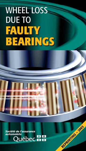
Wheel loss due to faulty bearings - Société de l'assurance ...
Wheel loss due to faulty bearings - Société de l'assurance ...
Wheel loss due to faulty bearings - Société de l'assurance ...

Create successful ePaper yourself
Turn your PDF publications into a flip-book with our unique Google optimized e-Paper software.
WHEEL LOSS<br />
DUE TO<br />
FAULTY<br />
BEARINGS<br />
REPRINTING – 2003
WHEEL LOSS<br />
DUE TO<br />
FAULTY<br />
BEARINGS<br />
Research and writing:<br />
Jean-Hugues Côté<br />
November 2000<br />
Service <strong>de</strong> la sécurité et <strong>de</strong> l’ingénierie <strong>de</strong>s véhicules<br />
1
ACKNOWLEDGMENTS<br />
2<br />
The author is grateful for the collaboration of the following<br />
persons in the preparation of this manual:<br />
❚<br />
❚<br />
❚<br />
❚<br />
❚<br />
❚<br />
❚<br />
❚<br />
❚<br />
Mr. Éthelbert Pelletier, Eng.<br />
Vice-presi<strong>de</strong>nt, Technical services<br />
Groupe Cabano Kingsway<br />
Mr. Gary Ballard<br />
Fleet manager<br />
Sgt 2000 inc.<br />
Mr. Pierre Coulombe<br />
Vehicle maintenance foreman<br />
Centre <strong>de</strong> formation en transport <strong>de</strong> Charlesbourg<br />
Mr. Denis Cayer<br />
Acci<strong>de</strong>nt prevention advisor<br />
Association sec<strong>to</strong>rielle transport entreposage (ASTE)<br />
Mr. Michel Savignac<br />
Career consellor<br />
Centre <strong>de</strong> formation en transport <strong>de</strong> Charlesbourg<br />
Mr. Denis Gosselin, Eng.<br />
Engineering direc<strong>to</strong>r, Manac<br />
Division of Groupe Canam Manac inc.<br />
Ms Josée Lessard, Eng.<br />
Manac, a division of Groupe Canam Manac inc.<br />
Mr. Bob Jackson<br />
Industrial division manager<br />
C.R. Chicago Rawhi<strong>de</strong><br />
Division of S.K.F.<br />
Mr. Gilbert Lacroix<br />
Education science specialist<br />
Société <strong>de</strong> l’assurance au<strong>to</strong>mobile du Québec
FOREWORD<br />
This manual, prepared by the road safety policy<br />
and programs division of the Société <strong>de</strong> l’assurance au<strong>to</strong>mobile<br />
du Québec, is inten<strong>de</strong>d <strong>to</strong> raise the awareness of<br />
heavy vehicle drivers and maintenance staff <strong>to</strong> the problems<br />
caused by <strong>de</strong>fective <strong>bearings</strong>. Faulty <strong>bearings</strong> have<br />
been known <strong>to</strong> cause wheel separation, resulting in fatal or<br />
serious acci<strong>de</strong>nts.<br />
This is not a text of law. For any question of a legal<br />
nature, please refer <strong>to</strong> the Highway Safety Co<strong>de</strong> and attendant<br />
regulations. The information contained in this manual<br />
does not bind the SAAQ.<br />
Please note that the masculine form is used in some<br />
instances <strong>to</strong> inclu<strong>de</strong> both gen<strong>de</strong>rs, with the sole intent of<br />
readability.<br />
Comments and suggestions concerning this manual<br />
may be addressed <strong>to</strong>:<br />
Service <strong>de</strong> la sécurité et <strong>de</strong><br />
l’ingénierie <strong>de</strong>s véhicules<br />
Direction <strong>de</strong>s politiques et <strong>de</strong>s<br />
programmes <strong>de</strong> sécurité routière<br />
Société <strong>de</strong> l’assurance au<strong>to</strong>mobile du Québec<br />
P.O. Box 19600<br />
333 boulevard Jean-Lesage, C-4-21<br />
Québec, Qc G1K 8J6<br />
3
TABLE<br />
OF CONTENTS<br />
1. INTRODUCTION 5<br />
2. RESPONSIBILITY 6<br />
3. WHAT TO LOOK FOR 8<br />
A. Drivers, during safety checks 8<br />
B. Drivers, on the road 8<br />
C. Maintenance staff, in the shop 10<br />
D. Signs of bearing <strong>de</strong>terioration 13<br />
4. MOUNTING BEARINGS 16<br />
A. Preparing parts 17<br />
B. Assembling <strong>bearings</strong> 18<br />
C. Oil seals damaged during installation 20<br />
D. Adjusting <strong>bearings</strong> 23<br />
E. Locking <strong>de</strong>vices 26<br />
Reference Tables 28<br />
Bibliography 30<br />
4
1. INTRODUCTION<br />
Defective <strong>bearings</strong>, which are generally the result<br />
of poor assembly, bad adjustment or improper lubrication,<br />
can cause wheel separation in heavy vehicles.<br />
This manual tells you how <strong>to</strong> <strong>de</strong>tect <strong>de</strong>fective <strong>bearings</strong>,<br />
either on the road or in the shop, and explains how<br />
<strong>to</strong> install and adjust <strong>bearings</strong> in accordance with generally<br />
accepted tra<strong>de</strong> practices and manufacturers’ specifications.<br />
5
2. RESPONSIBILITY<br />
This manual is aimed at making heavy vehicle<br />
owners, drivers and maintenance staff aware of the problem<br />
of wheel separation <strong>due</strong> <strong>to</strong> <strong>de</strong>fective <strong>bearings</strong>.<br />
The Société <strong>de</strong> l’assurance au<strong>to</strong>mobile du Québec<br />
consi<strong>de</strong>rs preventive maintenance and knowledge the best<br />
ways <strong>to</strong> prevent wheel <strong>loss</strong> and its potentially tragic consequences.<br />
◆<br />
THE OWNER<br />
The owner must see <strong>to</strong> it that his vehicles un<strong>de</strong>rgo<br />
preventive maintenance and that his staff has the knowhow<br />
and <strong>to</strong>ols necessary <strong>to</strong> <strong>de</strong>tect and repair problems.<br />
6
◆<br />
THE DRIVER<br />
In addition <strong>to</strong> conducting a daily safety check before<br />
setting out, as required by regulation, the driver is responsible<br />
for regularly checking his vehicle before resuming his<br />
travels after s<strong>to</strong>pping in a rest area or other suitable place.<br />
As the person closest <strong>to</strong> the vehicle, the driver can <strong>de</strong>tect<br />
anything out of the ordinary, particularly where potential<br />
wheel problems are concerned, and take appropriate<br />
action, thereby ensuring his own safety as well as that of<br />
other road users.<br />
◆<br />
THE PERSON IN CHARGE OF MAINTENANCE<br />
The person in charge of maintenance must see that<br />
the carrier’s preventive maintenance program contains a<br />
section on the installation, inspection and maintenance of<br />
wheel <strong>bearings</strong> in or<strong>de</strong>r <strong>to</strong> ensure that they remain in<br />
proper working or<strong>de</strong>r.<br />
7
3. WHAT TO LOOK FOR<br />
A. DRIVERS, DURING SAFETY CHECKS<br />
When conducting his daily safety check before starting<br />
out, the driver must pay particular attention <strong>to</strong> any<br />
trace of lubricant on the wheel hub or any part next <strong>to</strong> it.<br />
If there is a leak, the wheel <strong>bearings</strong> may not be lubricated<br />
enough, in which case the vehicle is not safe <strong>to</strong> drive.<br />
Or it may be an indication that there is no lubricant at all,<br />
which could spell disaster. In the short term, improper<br />
lubrication will cause the <strong>bearings</strong> <strong>to</strong> overheat and<br />
become damaged, possibly leading <strong>to</strong> wheel separation.<br />
The presence of lubricant anywhere near the wheel<br />
hub requires the immediate attention of a qualified<br />
mechanic <strong>to</strong> <strong>de</strong>termine the exact cause of the leak and<br />
make the necessary repairs before driving the vehicle<br />
again.<br />
B. DRIVERS, ON THE ROAD<br />
8<br />
When resting at a rest s<strong>to</strong>p or other appropriate<br />
location, drivers are encouraged <strong>to</strong> do another inspection<br />
similar <strong>to</strong> the safety check conducted before starting out.<br />
For example, they should look for traces of lubricant near<br />
the wheel hub.<br />
Other signs of <strong>de</strong>fective <strong>bearings</strong> may appear only<br />
after covering a certain distance, which is why drivers are<br />
urged <strong>to</strong> be particularly vigilant the next time they s<strong>to</strong>p<br />
after adjusting or repairing a wheel.<br />
Some of the signs of <strong>de</strong>fective <strong>bearings</strong> are:<br />
❚<br />
Lubricant on wheel parts. (Leaking can occur once<br />
you’ve left, particularly in a trailer that has been<br />
stationary for a long period of time);
❚<br />
❚<br />
❚<br />
A burnt smell emanating from a wheel;<br />
Smoke coming from insi<strong>de</strong> the wheel;<br />
On a wet wheel, water evaporating from the surface<br />
of the hub and the hub drying quickly;<br />
❚ Strong heat near a wheel.<br />
If any of the above signs are present, carefully check<br />
the hub temperature. If the hub is hot, i.e. if you can feel<br />
the heat just by approaching the hub, stay back and wait<br />
until it cools enough for a closer examination. The heat<br />
from the wheel could cause the air pressure insi<strong>de</strong> the tires<br />
<strong>to</strong> rise, which in turn represents a risk of tire bursting.<br />
Remember that the temperature on a rig which has been<br />
s<strong>to</strong>pped is likely <strong>to</strong> be higher for a while <strong>due</strong> <strong>to</strong> reduced air<br />
passage over the area. Do not, un<strong>de</strong>r any circumstances,<br />
get back on the roadway until you have i<strong>de</strong>ntified the exact<br />
cause of the problem. However, it is important <strong>to</strong> remember<br />
that braking can also cause wheels <strong>to</strong> heat. To properly<br />
assess the situation, then, ask yourself whether or not<br />
the wheel in question is hotter than the others.<br />
9
C. MAINTENANCE STAFF, IN THE SHOP<br />
<strong>Wheel</strong> <strong>bearings</strong> should au<strong>to</strong>matically be inspected<br />
by a qualified mechanic during preventive maintenance.<br />
In fact, one of the mechanic’s main responsibilities<br />
is <strong>to</strong> evaluate wear and replace any vehicle parts that risk<br />
breaking or failing before the next scheduled maintenance<br />
check.<br />
The mechanic has all the equipment he needs in the<br />
shop <strong>to</strong> conduct a thorough inspection of wheel <strong>bearings</strong>.<br />
Although this inspection is different from the one carried<br />
out by the driver during roadsi<strong>de</strong> s<strong>to</strong>ps, lubricant on the<br />
outsi<strong>de</strong> components of wheels still indicates a problem<br />
requiring immediate attention.<br />
To inspect wheel <strong>bearings</strong> in the shop, proceed as<br />
follows:<br />
N.B. Safety equipment such as goggles, appropriate<br />
footwear and clothing should be worn for the<br />
optimal protection of maintenance staff.<br />
❚ Check <strong>to</strong> see if there is enough lubricant;<br />
❚<br />
❚<br />
❚<br />
Using a magnet, check for pieces of metal in the<br />
lubricant. To do this, remove the center fill cap or<br />
the plug from the filler port and insert a magnet in<br />
the fluid;<br />
Check for water in the lubricant (N.B. Water can<br />
infiltrate the hub cap when vehicles are pressure-washed.<br />
The people who do this job<br />
should be alerted <strong>to</strong> the problem.);<br />
Place chocks un<strong>de</strong>r the wheels and release the<br />
parking brake;<br />
10
❚<br />
Jack the vehicle, rotate the wheel and listen for any<br />
unusual noises;<br />
❚ For single-wheel assemblies, check the bearing end<br />
play by grasping the <strong>to</strong>p and bot<strong>to</strong>m of the wheel,<br />
in a swinging movement from the insi<strong>de</strong> outward.<br />
For dual-wheel assemblies, we recommend using a<br />
pry bar, given the weight <strong>to</strong> be moved. (N.B.<br />
There should be zero end play).<br />
If there is water or pieces of metal in the lubricant,<br />
or if there is end play in the <strong>bearings</strong>, remove the wheel as<br />
follows (the wheel will have been raised <strong>to</strong> check for end<br />
play):<br />
❚ Place safety stands un<strong>de</strong>r the vehicle.<br />
❚ Allow the vehicle chassis <strong>to</strong> rest on the stands.<br />
❚<br />
❚<br />
❚<br />
❚<br />
❚<br />
❚<br />
Remove the hub cap, or axle shaft in the case of a<br />
drive axle.<br />
Loosen the jam nut, if there is one, and the adjusting<br />
nut.<br />
Remove the outer bearing.<br />
Using a wheel dolly, remove the wheel <strong>to</strong> locate<br />
the source of the metal in the lubricant.<br />
After removing the wheel, remove and thoroughly<br />
clean the <strong>bearings</strong>.<br />
Always use a new oil seal during reassembly.<br />
11
❚<br />
❚<br />
❚<br />
Carefully inspect all parts of the locking <strong>de</strong>vice,<br />
nuts and jam nuts, and if damaged or unserviceable,<br />
replace with new ones.<br />
Carefully inspect the contact surfaces of <strong>bearings</strong>.<br />
Replace the <strong>bearings</strong> if they are worn or show any<br />
signs of <strong>de</strong>terioration, such as illustrated opposite.<br />
Even if just one bearing shows signs of <strong>de</strong>terioration,<br />
both must be replaced.<br />
❚ Follow the procedure <strong>de</strong>scribed on page 16 for<br />
reassembly.<br />
❚ Always use a new oil seal.<br />
N.B. We recommend removing wheels and closely<br />
inspecting <strong>bearings</strong> every 500,000 km. This inspection<br />
can be carried out at the same time as other<br />
repairs, such as during brake replacement.<br />
12
D. SIGNS OF BEARING DETERIORATION<br />
A bearing that shows any of the following signs of<br />
<strong>de</strong>terioration must be changed.<br />
Figure 1<br />
Pieces of metal or grit in the lubricant.<br />
Figure 2<br />
Pieces of metal or grit in the lubricant.<br />
13
Figure 3<br />
Pieces of metal or grit in the lubricant.<br />
Figure 4<br />
Chipping on the outer edge at the wi<strong>de</strong>st diameter of the<br />
tapered roller: indicates that bearing is <strong>to</strong>o tight .<br />
14
Figure 5<br />
Chipping on the outer edge at the narrowest diameter of the<br />
tapered roller: indicates that bearing is <strong>to</strong>o loose.<br />
Figure 6<br />
A bearing that is <strong>to</strong>o tight can lead <strong>to</strong> premature wear of its<br />
inner race.<br />
15
4. MOUNTING<br />
BEARINGS<br />
Mounting <strong>bearings</strong> is tricky and requires careful<br />
attention on the part of the person doing it. This section<br />
<strong>de</strong>scribes a standard procedure that complies with generally<br />
accepted tra<strong>de</strong> practices and is recognized as efficient<br />
by the industry. Note that this procedure uses tapered<br />
roller <strong>bearings</strong> (see illustration below) <strong>de</strong>signed in keeping<br />
with similar performance standards, regardless of the<br />
make. The manufacturer’s specifications should be used if<br />
different from below.<br />
16
To mount <strong>bearings</strong>, proceed as follows:<br />
A. PREPARING PARTS<br />
❚<br />
❚<br />
❚<br />
❚<br />
❚<br />
❚<br />
❚<br />
Clean the spindle <strong>to</strong> remove any traces of lubricant<br />
or dirt.<br />
Buff any acci<strong>de</strong>ntal <strong>to</strong>ol marks using a smooth file<br />
or emery cloth of the appropriate coarseness.<br />
Where necessary, polish the entire spindle surface<br />
using an emery cloth. The shoul<strong>de</strong>rs and bearing<br />
surfaces must be smooth and free of burrs.<br />
Clean thoroughly with a clean cloth <strong>to</strong> remove any<br />
grit.<br />
Remove the hub <strong>bearings</strong> and cups, being careful<br />
not <strong>to</strong> damage the bearing housings.<br />
Clean any traces of lubricant or dirt off the hub.<br />
Buff any acci<strong>de</strong>ntal <strong>to</strong>ol marks. The shoul<strong>de</strong>rs and<br />
bearing cups must be smooth and free of burrs.<br />
17
B. ASSEMBLING BEARINGS<br />
❚<br />
❚<br />
❚<br />
❚<br />
❚<br />
❚<br />
❚<br />
❚<br />
Make sure new parts are i<strong>de</strong>ntical or equivalent <strong>to</strong><br />
the parts being replaced.<br />
Use the proper <strong>to</strong>ols <strong>to</strong> ensure the bearing cups<br />
and oil seal are installed correctly. 1<br />
Use manufacturer-recommen<strong>de</strong>d <strong>to</strong>ols.<br />
Using the proper <strong>to</strong>ol, place the inner bearing cup<br />
in the hub housing.<br />
Lubricate the conal assembly using clean oil and<br />
insert it in the cup. Use the same type of lubricant<br />
as for the axle housing.<br />
Put the oil seal on the insertion <strong>to</strong>ol. Use sealing<br />
material, or lubricate the ring according <strong>to</strong> the<br />
manufacturer’s recommendations.<br />
Insert the oil seal in the wheel hub. (N.B. Certain<br />
types of oil seals must be mounted directly on<br />
the spindle. In this case, the oil seal and inner<br />
bearing must be placed on the spindle before<br />
putting the wheel back on.)<br />
Rotate the wheel and place the outer bearing cup<br />
in its housing using the proper <strong>to</strong>ol.<br />
18<br />
1. To facilitate the task and prevent dis<strong>to</strong>rtion, we highly recommend using a specially<br />
<strong>de</strong>signed <strong>to</strong>ol <strong>to</strong> install bearing cups and oil seals. Oil seals are particularly<br />
fragile and the wrong <strong>to</strong>ol can easily cause dis<strong>to</strong>rtion, which can prevent<br />
the bearing from functioning properly and eventually lead <strong>to</strong> premature lubricant<br />
leaking. The pages of this section contain some illustrations of oil seals<br />
which were damaged during installation <strong>due</strong> <strong>to</strong> the use of improper <strong>to</strong>ols or<br />
carelessness.
❚<br />
Put the wheel back on using a wheel dolly, proceeding<br />
as follows:<br />
❚<br />
❚<br />
❚<br />
❚<br />
❚<br />
❚<br />
❚<br />
❚<br />
❚<br />
❚<br />
❚<br />
❚<br />
❚<br />
First of all, make sure the wheel dolly<br />
is in good working or<strong>de</strong>r.<br />
Sweep the floor <strong>to</strong> remove any <strong>de</strong>bris that may<br />
block the dolly wheels and cause jarring. 2<br />
Align the wheel hub and spindle.<br />
Gently push the wheel in<strong>to</strong> place, being careful<br />
not <strong>to</strong> damage the insi<strong>de</strong> of the oil seal.<br />
Lubricate the outer cone assembly using clean<br />
oil and insert it in the cup.<br />
Adjust the bearing according <strong>to</strong> the procedure<br />
indicated in the section “Adjusting Bearings”.<br />
Put the hub cap on after examining it carefully.<br />
Use a new gasket.<br />
Fill the hub with clean oil <strong>to</strong> the specified level.<br />
Spin the wheel a few times and leave for around<br />
5 minutes.<br />
If nee<strong>de</strong>d, adjust the amount of lubricant<br />
one last time.<br />
Put back the center fill cap or plug from the filler<br />
port, <strong>de</strong>pending on the wheel type.<br />
Wipe any oil off the wheel hub so that the next<br />
user doesn’t mistake it for a leak.<br />
2. If any <strong>de</strong>bris blocks the dolly wheels, it can cause jarring and damage the insi<strong>de</strong><br />
of the ring seal if the latter bangs in<strong>to</strong> the spindle.<br />
19
C. OIL SEALS DAMAGED<br />
DURING INSTALLATION<br />
The following figures illustrate oil seals which have<br />
been damaged during installation.<br />
Figure 7<br />
Figure 8<br />
Dis<strong>to</strong>rtion of metal casing <strong>due</strong> <strong>to</strong> use of the wrong <strong>to</strong>ols<br />
20
Figure 9<br />
21
Figure 10<br />
Damage caused by contact between the insi<strong>de</strong> of the oil seal and<br />
the spindle<br />
This can result from poor hub/spindle alignment, ina<strong>de</strong>quate<br />
flooring, a dirty floor or carelessness.<br />
Figure 11<br />
Damage caused by contact between the insi<strong>de</strong> of the oil seal and<br />
the spindle<br />
This can result from poor hub/spindle alignment, ina<strong>de</strong>quate<br />
flooring, a dirty floor or carelessness.<br />
22
D. ADJUSTING BEARINGS<br />
Bearings must be adjusted according <strong>to</strong> the type of<br />
axle involved, since the role and position differ for each,<br />
i.e.:<br />
❚ Steering axle.<br />
❚ Drive axle.<br />
❚ Trailer axle.<br />
Depending on the type of axle, adjust <strong>bearings</strong> as<br />
follows:<br />
❚ Lubricate spindle threads.<br />
❚ Screw the adjusting nut on the spindle thread.<br />
❚ *<br />
Set a bearing preloading by <strong>to</strong>rquing the adjusting<br />
nut <strong>to</strong> 200 ft-lbs <strong>to</strong> make up for any play between<br />
parts.<br />
N.B. This step must be carried out while rotating<br />
the wheel.<br />
❚ Loosen the adjusting nut one complete turn.<br />
❚ Now tighten it again <strong>to</strong> a 50 ft-lbs <strong>to</strong>rque.<br />
❚<br />
❚<br />
*<br />
Loosen the nut 1/6 <strong>to</strong> 1/2 turn <strong>de</strong>pending on the<br />
axle type (see Reference Table pp. 28, 29); while<br />
doing so, <strong>de</strong>termine the right position for the locking<br />
<strong>de</strong>vice.<br />
Install the locking <strong>de</strong>vice.<br />
23
❚<br />
*<br />
Screw the jam nut on the spindle thread and tighten<br />
<strong>to</strong> the recommen<strong>de</strong>d <strong>to</strong>rque level (see Table,<br />
pp. 28, 29).<br />
❚ Before putting the hub cap on, measure the play<br />
using a dial gauge as illustrated below.<br />
N.B. Play should be between 0.001” and 0.005”<br />
(from one <strong>to</strong> five thousandths of an inch).<br />
While the above procedure is suitable in most cases,<br />
the Table on pages 28 and 29 must be consulted <strong>to</strong> <strong>de</strong>termine<br />
the appropriate <strong>to</strong>rque levels for jam nuts and the<br />
type of locking <strong>de</strong>vice <strong>to</strong> be used. However, if components<br />
differ from those referred <strong>to</strong> in this document, the manufacturer’s<br />
specifications must be followed.<br />
24<br />
*<br />
Use of a <strong>to</strong>rque wrench is essential; do not use<br />
an impact wrench for this operation.
E. LOCKING DEVICES<br />
The locking <strong>de</strong>vice ensures that <strong>to</strong>rque levels are<br />
maintained once <strong>bearings</strong> have been mounted. The installation<br />
of locking <strong>de</strong>vices and the <strong>to</strong>rque level vary with the<br />
❚<br />
Dowell type locking <strong>de</strong>vice<br />
❚<br />
Tang type locking <strong>de</strong>vice<br />
❚<br />
Single-nut locking <strong>de</strong>vice<br />
26
mo<strong>de</strong>l, diameter and thread pitch of the spindle used. The<br />
most common locking <strong>de</strong>vices are illustrated below.<br />
27
REFERENCE TABLES<br />
BEARING ADJUSTMENT<br />
Axle type<br />
Initial adjustment<br />
Final adjustment<br />
Steering axle<br />
• Torque <strong>to</strong> 200 ft-lbs<br />
•Loosen 1 turn<br />
❚ Single nut<br />
•Torque <strong>to</strong> 50 ft-lbs<br />
•Loosen 1/6 turn<br />
for 12 threads/in.,<br />
•Loosen 1/4 turn<br />
for 18 threads/in.<br />
❚ Double nut<br />
•Torque <strong>to</strong> 50 ft-lbs<br />
•Loosen 1/2 turn<br />
in all cases<br />
Torque level for jam-nutsSee table below...<br />
BEARING ADJUSTMENT<br />
Recommen<strong>de</strong>d <strong>to</strong>rque level for jam nuts<br />
Axle type<br />
Steering axle<br />
Locking <strong>de</strong>vice<br />
Double nut adjustment<br />
Drive axle<br />
Tang type locking <strong>de</strong>vice<br />
Drive axle<br />
Dowell type locking <strong>de</strong>vice<br />
28<br />
Trailer <strong>de</strong>vice
N.B.<br />
Use of a <strong>to</strong>rque wrench is essential for tightening <strong>to</strong> the recommen<strong>de</strong>d<br />
values; do not use an impact wrench for this.<br />
Drive axle<br />
•Torque <strong>to</strong> 200 ft-lbs<br />
•Loosen 1 turn<br />
•Torque <strong>to</strong> 50 ft-lbs<br />
•Loosen 1/4 turn<br />
in all cases<br />
Trailer axle<br />
• Torque <strong>to</strong> 200 ft-lbs<br />
• Loosen 1 turn<br />
• Torque <strong>to</strong> 50 ft-lbs<br />
• Loosen 1/4 turn<br />
in all cases<br />
Torque level<br />
200 - 300 ft-lbs nut of 2 5 ⁄8 in. or less<br />
300 - 400 ft-lbs nut of more than 2 5 ⁄8 in.<br />
200 - 275 ft-lbs<br />
300 - 400 ft-lbs<br />
200 - 300 ft-lbs nut of 2 5 ⁄8 in. or less<br />
300 - 400 ft-lbs nut of more than 2 5 ⁄8 in.<br />
29
BIBLIOGRAPHY<br />
C.R. Chicago Rawhi<strong>de</strong>-S.K.F. , Brochure 4 .<br />
T.M.C. The Maintenance Council, Recommen<strong>de</strong>d<br />
Maintenance Practices Manual 1994-1995. Page 29.<br />
Mack, Truck Maintenance Manual.<br />
Kenworth, Maintenance Manual.<br />
30
C-3104-A