Service Info No. 51-03 - DG Flugzeugbau
Service Info No. 51-03 - DG Flugzeugbau
Service Info No. 51-03 - DG Flugzeugbau

You also want an ePaper? Increase the reach of your titles
YUMPU automatically turns print PDFs into web optimized ePapers that Google loves.
<strong>DG</strong> <strong>Flugzeugbau</strong> GmbH<br />
76646 Bruchsal<br />
Subject :<br />
Effectivity :<br />
Accomplishment :<br />
Reason :<br />
Instructions :<br />
Material :<br />
Weight and balance :<br />
<strong>Service</strong> <strong>Info</strong> page 1 from 2<br />
<strong>No</strong>. <strong>51</strong>-<strong>03</strong><br />
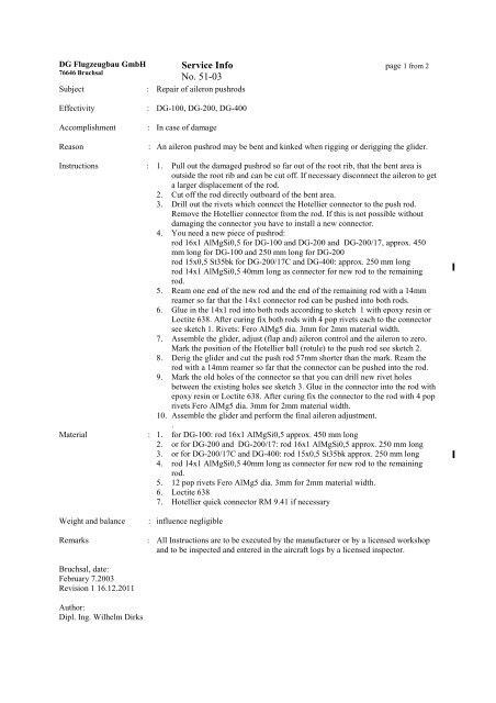
Repair of aileron pushrods<br />
<strong>DG</strong>-100, <strong>DG</strong>-200, <strong>DG</strong>-400<br />
In case of damage<br />
An aileron pushrod may be bent and kinked when rigging or derigging the glider.<br />
1. Pull out the damaged pushrod so far out of the root rib, that the bent area is<br />
outside the root rib and can be cut off. If necessary disconnect the aileron to get<br />
a larger displacement of the rod.<br />
2. Cut off the rod directly outboard of the bent area.<br />
3. Drill out the rivets which connect the Hotellier connector to the push rod.<br />
Remove the Hotellier connector from the rod. If this is not possible without<br />
damaging the connector you have to install a new connector.<br />
4. You need a new piece of pushrod:<br />
rod 16x1 AlMgSi0,5 for <strong>DG</strong>-100 and <strong>DG</strong>-200 and <strong>DG</strong>-200/17, approx. 450<br />
mm long for <strong>DG</strong>-100 and 250 mm long for <strong>DG</strong>-200<br />
rod 15x0,5 St35bk for <strong>DG</strong>-200/17C and <strong>DG</strong>-400: approx. 250 mm long<br />
rod 14x1 AlMgSi0,5 40mm long as connector for new rod to the remaining<br />
rod.<br />
5. Ream one end of the new rod and the end of the remaining rod with a 14mm<br />
reamer so far that the 14x1 connector rod can be pushed into both rods.<br />
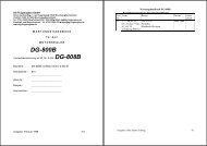
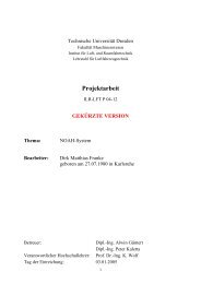
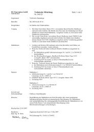
6. Glue in the 14x1 rod into both rods according to sketch 1 with epoxy resin or<br />
Loctite 638. After curing fix both rods with 4 pop rivets each to the connector<br />
see sketch 1. Rivets: Fero AlMg5 dia. 3mm for 2mm material width.<br />
7. Assemble the glider, adjust (flap and) aileron control and the aileron to zero.<br />
Mark the position of the Hotellier ball (rotule) to the push rod see sketch 2.<br />
8. Derig the glider and cut the push rod 57mm shorter than the mark. Ream the<br />
rod with a 14mm reamer so far that the connector can be pushed into the rod.<br />
9. Mark the old holes of the connector so that you can drill new rivet holes<br />
between the existing holes see sketch 3. Glue in the connector into the rod with<br />
epoxy resin or Loctite 638. After curing fix the connector to the rod with 4 pop<br />
rivets Fero AlMg5 dia. 3mm for 2mm material width.<br />
10. Assemble the glider and perform the final aileron adjustment.<br />
.<br />
1. for <strong>DG</strong>-100: rod 16x1 AlMgSi0,5 approx. 450 mm long<br />
2. or for <strong>DG</strong>-200 and <strong>DG</strong>-200/17: rod 16x1 AlMgSi0,5 approx. 250 mm long<br />
3. or for <strong>DG</strong>-200/17C and <strong>DG</strong>-400: rod 15x0,5 St35bk approx. 250 mm long<br />
4. rod 14x1 AlMgSi0,5 40mm long as connector for new rod to the remaining<br />
rod.<br />
5. 12 pop rivets Fero AlMg5 dia. 3mm for 2mm material width.<br />
6. Loctite 638<br />
7. Hotellier quick connector RM 9.41 if necessary<br />
influence negligible<br />
Remarks : All Instructions are to be executed by the manufacturer or by a licensed workshop<br />
and to be inspected and entered in the aircraft logs by a licensed inspector.<br />
Bruchsal, date:<br />
February 7.20<strong>03</strong><br />
Revision 1 16.12.2011<br />
Author:<br />
Dipl. Ing. Wilhelm Dirks
Sketch 2<br />
Sketch 3<br />
Sketch 1<br />
20<br />
40<br />
<strong>Service</strong> <strong>No</strong>. <strong>51</strong>-<strong>03</strong><br />
rivets<br />
10<br />
page 2 from 2