special publication - Fusion For Energy - Europa
special publication - Fusion For Energy - Europa
special publication - Fusion For Energy - Europa

You also want an ePaper? Increase the reach of your titles
YUMPU automatically turns print PDFs into web optimized ePapers that Google loves.
Conceptual Evaluation 1 –<br />
of design vibration finalization effects on of the IVVS ITER (In<br />
In-Vessel Viewing System) and Metrology images and System vibration (IVVS)<br />
correction method<br />
G.Dubus C. Neri a , a P. , A.Puiu Costa a , C. M. Damiani Ferri a , a M. , A. Florean Lo Bue a , J. G. Izquierdo Mugnaini a , a , L. M. Semeraro Pillon a , F. a , J.‐P. Pollastrone Martins a , b , P. J. Rossi Palmer a , C.Damiani b , et al.<br />
b ,<br />
G. Dubus b<br />
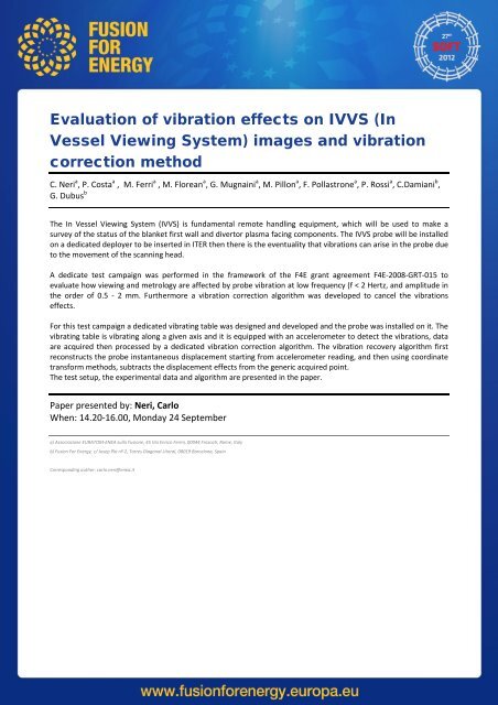
The In‐Vessel Viewing and Metrology System (IVVS) is a fundamental tool of the ITER Remote Maintenance System<br />
(IRMS), The In Vessel aiming Viewing at performing System (IVVS) inspections is fundamental as well as remote providing handling information equipment, related which to the will erosion be used of to in‐vessel make a<br />
components. survey of the status Periodically of the or blanket on request first wall (in and case divertor of unforeseen plasma facing events: components. plasma disruptions, The IVVS probe suspected will be damages, installed<br />
presence on a dedicated of particles,...), deployer to the be IVVS inserted probes in ITER will be then deployed there is into the eventuality the Vacuum that Vessel vibrations (VV) from can their arise storage in the probe positions due<br />
to (still the within movement the ITER of the primary scanning confinement) head. in order to perform both viewing and metrology on plasma facing<br />
components (blanket, divertor, heating/diagnostic plugs, test blanket modules) and, more generically, to provide<br />
A information dedicate test on the campaign status of was the in performed vessel components. in the framework of the F4E grant agreement F4E‐2008‐GRT‐015 to<br />
evaluate how viewing and metrology are affected by probe vibration at low frequency (f < 2 Hertz, and amplitude in<br />
In the 2011, order a of Project 0.5 ‐ 2 Change mm. Furthermore Request (PCR) a vibration raised correction by the IO algorithm proposed was to developed simplify and to cancel strengthen the vibrations the six<br />
effects. IVV penetrations situated at the divertor level. Among other important consequences, such as the relocation of the<br />
GDC electrodes at other levels of the machine, this PCR had a major impact on the layout of the IVV port extension<br />
itself. <strong>For</strong> this It test implied campaign the need a dedicated for a substantial vibrating redesign table was of designed the IVVS and plug, developed which took and part the to probe an on‐going was installed effort on to it. bring The<br />
the vibrating integrated table is IVVS vibrating concept along – including a given axis the and scanning it is equipped probe and with its an deployment accelerometer system to detect – to the the level vibrations, of maturity data<br />
suitable are acquired for the then Conceptual processed Design by a Review dedicated (CDR). vibration correction algorithm. The vibration recovery algorithm first<br />
reconstructs the probe instantaneous displacement starting from accelerometer reading, and then using coordinate<br />
This transform paper methods, gives an overview subtracts of the the displacement various design effects and R&D from activities the generic in progress acquired for point. the IVVS main subsystems: plug<br />
design The test integration, setup, the experimental actuation concept data and design, algorithm probe are concept presented design in finalization the paper. and validation under environmental<br />
conditions, improvement of the in‐vessel coverage for viewing and metrology, development of a metrology strategy,<br />
the whole being supported by gamma, neutronics and mechanical analyses.<br />
Paper presented by: Neri, Carlo<br />
When: 14.20‐16.00, Monday 24 September<br />
Paper presented by: Van Uffelen, Marco<br />
When: 14.20‐16.00, Tuesday 25 September<br />
a) Associazione EURATOM‐ENEA sulla <strong>Fusion</strong>e, 45 Via Enrico Fermi, 00044 Frascati, Rome, Italy<br />
a)<br />
b) <strong>Fusion</strong> <strong>For</strong> for <strong>Energy</strong>, c/ Barcelona, Josep Pla nº Spain 2, Torres Diagonal Litoral, 08019 Barcelona, Spain<br />
b) ITER Organization, Cadarache, France<br />
Corresponding author: carlo.neri@enea.it<br />
gregory.dubus@f4e.europa.eu
The 1 –<br />
conceptual design of the IVVS control and<br />
acquisition system<br />
C. Neri 1 , M. Riva 1 , M. Florean 1 , F. Pollastrone 1 , C.Damiani 2 , G. Dubus 2<br />
The IVVS (In Vessel Viewing System) is a laser scanning 3D image system, developed to work under the ITER harsh<br />
environment (high radiation, high magnetic field, high temperature and high vacuum conditions). The project is<br />
currently developed under a F4E Grant framework.<br />
The architecture for the full IVVS system, consisting in six probes and relative electronic hardware, has been<br />
designed considering various different layouts, aiming to obtain the best 3D quality image.<br />
The IVVS is a complex device. The presence of a control system is foreseen for various fundamental control activities<br />
like scanning prism motors, focus system motors, optical encoders position measurements and acquisition of several<br />
status sensors, including End Of Run (EOR), temperature measurements, and possibly a 3D accelerometer to be used<br />
for correcting the vibration effect on the acquired images.<br />
The low level hardware architecture is based on two dedicated subsystems for each probe; the PFE (Probe Front<br />
End) and the PCU (Probe Control Unit). In the high level an SMU (System Management Unit) based on a specific<br />
workstation it is necessary to set, control and arbitrate acquisition requests to the six IVVS probes and some CADVS<br />
(Control and data Visualization System) are necessary to set‐up the image acquisitions, initiate the acquisitions, to<br />
visualize and post‐elaborate the acquired images.<br />
The PFE subsystem, being located in the ITER buildings, near the bio‐shield, must satisfy many requirements, mainly<br />
due to geometrical and radiation constraints as this area can be affected by a secondary radiation flux during the<br />
remote handling operations. The architecture of the PFE is limited to the electronic subcomponents that need to be<br />
positioned in the port cell to avoid a deterioration in the IVVS characteristics.<br />
In the paper, the chosen layout is presented. The hardware and software architecture are described and an analysis<br />
on the various physical connections (fiber optics, electrical connections, cabling, etc.) and software interfaces is<br />
carried out.<br />
Paper presented by: Florean, Marco<br />
When: 14.20‐16.00, Monday 24 September 2012<br />
1) Associazione EURATOM‐ENEA sulla <strong>Fusion</strong>e, 45 Via Enrico Fermi, 00044 Frascati, Rome, Italy<br />
2) <strong>Fusion</strong> <strong>For</strong> <strong>Energy</strong>, c/ Josep Pla nº 2, Torres Diagonal Litoral, 08019 Barcelona, Spain<br />
Corresponding author: carlo.neri@enea.it
Characterization 1 –<br />
of Superconducting Wires and<br />
Cables by X-ray Micro-Tomography<br />
I. Tiseanu 1 , L. Zani 2<br />
Due to their mechanical strength and ability to withstand the large electromagnetic force applied to the<br />
superconductors in large magnets during excitation, the Cable‐in‐Conduit‐Conductor (CICC) type superconductors<br />
will be applied in the next stage of fusion magnets. Thus, the TF coil in JT‐60SA and the PF coil in ITER would rely on<br />
twisted multi_lament NbTi‐based composite strands with copper strands. The strands are cabled and the cable is<br />
jacketed to become a CICC. It is demonstrated that the cable twist pitch (TP) and void fraction (VF) may have a<br />
substantial impact on the CCIC performances. Here, we discuss the recent results on the application of a noninvasive<br />
method for the characterization of superconducting strands and cables by X‐ray micro‐tomography (_XCT).<br />
The experiments have been carried out on a high resolution X‐ray micro‐tomography facility in INFLPR<br />
(http://tomography.inpr.ro). An open type nanofocus X‐ray source with maximum high voltage of 225 kVp at 15‐30<br />
W maximum power and multiple targets of W on di_erent windows materials (Be, Al or diamond) is the main<br />
component. X‐rays are detected by means of a high resolution amorphous silicon at panel sensor in the cone‐beam<br />
scanning con_guration and high energy e_cient line sensor based on individual scintillators in the fan‐beam scanning<br />
con_guration. The micro‐radiography analysis is guaranteed for sub‐micron feature recognition. Tomographic image<br />
reconstructions are obtained by a proprietary highly optimized code with visualization and 3D virtual navigation<br />
within the reconstructed volume. The reconstructed volume is post‐processed by proprietary algorithms in order to<br />
compensate for the inherent tomography artifacts.<br />
Our method provides:<br />
i) determination of the local and global void fraction (over a 300 mm length of the sample),<br />
ii) void homogeneity factor, related to the ratio between void space surface and perimeter in 2D crosssection,<br />
iii) cos(teta) – the ratio between the volume of strands in conductor (provided that their trajectories were<br />
straight) and the measured one. The determination of the strand trajectories along the sample in 3‐D<br />
coordinates format represents the key ingredient for obtaining these parameters. Several algorithms<br />
for detection of multiple touching circles on gray‐scale images were applied in order to determine the<br />
interstrand contact linear density (the number of interstrand contacts per meter of conductor). This<br />
methodology is applied for the quality control monitoring of NbTi strands and conductor for JT‐60SA TF<br />
coils: "Extended geometry".<br />
Paper presented by: Tiseanu, Ion<br />
When: 14.20‐16.00, Monday 24 September<br />
(1) INFLPR<br />
(2) F4E Barcelona
Assessment 1 –<br />
of the dynamic behaviours of<br />
the ITER Vacuum Vessel<br />
Jacek Blocki a , Didier Combescure a<br />
The design of Safety Important Components such as the ITER vacuum Vessel and the Tokamak Complex<br />
Structure has to consider important dynamic loads corresponding to internal or external hazards (plasma<br />
disruptions, earthquake, etc...). An accurate estimation of the dynamic response (in term of stresses,<br />
accelerations, displacements, etc...) of the detailed FEM models used for these components is mandatory for a<br />
project such as the ITER Fission Facility.<br />
An assessment of the dynamic behaviour of the ITER Vacuum Vessel has been performed using two different<br />
finite element models, one based on shells elements 1 and the second based on solid elements 2 . These in‐house<br />
calculations have been used for the preparation and the follow‐up of the work done by F4E suppliers. At the<br />
beginning, eigenvalues and eigenmodes were checked. Two different methods which are available in the ANSYS<br />
code have been applied, that is, the cyclic symmetry method and the Component Mode Synthesis (CMS)<br />
method. Obtained frequency values for the old and new type of the main support have been compared.<br />
In the seismic analysis, the response spectrum method with two floor response spectrum, one proposed by the<br />
ITER Organization 3 and the second proposed by IDOM 4 has been used.<br />
The 360 deg finite element model has been developed and the CMS method has been applied leaving one 40<br />
deg sector not changed to a substructure. Such a procedure speeds up the calculations because there is no<br />
need to expand solutions for the substructures.<br />
<strong>For</strong> the first vertical eigenfrequency and for the two horizontal eigenfrequencies the ratio of the effective mass<br />
to the total mass is equal to 0.80 and 0.92, respectively. <strong>For</strong> this reason, the modal combination of the<br />
spectrum response is based on these three eigenfrequencies and on the missing mass effect. <strong>For</strong> the horizontal<br />
eigenmodes, an algebraic summation of the modal components has been applied. Finally, to calculate<br />
deformation shapes and stresses the Newmark rule was used. Described above procedure avoids the problem<br />
of losing a sign of the stress components when the square root sum of the squares (SSRS) or the complete<br />
quadratic combination (CQC) method is applied. <strong>For</strong> the seismic analysis, this simplification is also helped by<br />
the fact the seismic isolation makes the horizontal seismic load almost static for the components having the<br />
fundamental eigenfrequencies higher than the cut‐off frequency of the isolation system.<br />
Paper presented by: Blocki, Jacek<br />
When: 14.20‐16.00, Monday 24 September<br />
a) 1<strong>Fusion</strong> for <strong>Energy</strong>, Josep Pla, 2 – Torres Diagonal Litoral B3, 08019 Barcelona, Spain<br />
1) C.Bachmann, 40o Shell Model of the ITER Vacuum Vessel Standard Sector #01, ITER_D_24APAE, (17/12/2008),<br />
2) NATEC, IBERDROLA, ELYTT ENERGY, VV Regular Sector S‐Type Damage Stress Report, F4E_D_242DR7 (25/01/2012),<br />
3) Energopul LTD., SEISMIC ANALYSIS OF THE TOKAMAK BUILDING ASSEMBLY AND THE MAIN TOKAMAK COMPONENTS, ITER_D_ 33W3P4, (April 2011),<br />
4) IDOM, SEISMIC INPUT FOR ISOLATED ANALYSES OF THE VACUUM VESSEL, F4E_D_248YVQ v1.1 , (14/09/2011)
Assessment 1 –<br />
of the dynamic behaviours of the<br />
ITER Vacuum Vessel<br />
Jacek Blocki a , Didier Combescure a<br />
The design of Safety Important Components such as the ITER vacuum Vessel and the Tokamak Complex Structure has<br />
to consider important dynamic loads corresponding to internal or external hazards (plasma disruptions, earthquake,<br />
etc...). An accurate estimation of the dynamic response (in term of stresses, accelerations, displacements, etc...) of<br />
the detailed FEM models used for these components is mandatory for a project such as the ITER Fission Facility.<br />
An assessment of the dynamic behaviour of the ITER Vacuum Vessel has been performed using two different finite<br />
element models, one based on shells elements [1] and the second based on solid elements [2]. These in‐house<br />
calculations have been used for the preparation and the follow‐up of the work done by F4E suppliers. At the<br />
beginning, eigenvalues and eigenmodes were checked. Two different methods which are available in the ANSYS code<br />
have been applied, that is, the cyclic symmetry method and the Component Mode Synthesis (CMS) method.<br />
Obtained frequency values for the old and new type of the main support have been compared.<br />
In the seismic analysis, the response spectrum method with two floor response spectrum, one propoed by the ITER<br />
Organization [3] and the second proposed by IDOM [4] has been used.<br />
The 360 deg finite element model has been developed and the CMS method has been applied leaving one 40 deg<br />
sector not changed to a substructure. Such a procedure speeds up the calculations because there is no need to<br />
expand solutions for the substructures.<br />
<strong>For</strong> the first vertical eigenfrequency and for the two horizontal eigenfrequencies the ratio of the effective mass to<br />
the total mass is equal to 0.80 and 0.92, respectively. <strong>For</strong> this reason, the modal combination of the spectrum<br />
response is based on these three eigenfrequencies and on the missing mass effect. <strong>For</strong> the horizontal eigenmodes,<br />
an algebraic summation of the modal components have been applied. Finally, to calculate deformation shapes and<br />
stresses the Newmark rule was used. Described above procedure avoids the problem of losing a sign of the stress<br />
components when the square root sum of the squares (SSRS) or the complete quadratic combination (CQC) method<br />
is applied. <strong>For</strong> the seismic analysis, this simplification is also helped by the fact the seismic isolation makes the<br />
horizontal seismic load almost static for the components having the fundamental eigenfrequencies higher than the<br />
cut‐off frequency of the isolation system.<br />
Paper presented by: Blocki, Jacek<br />
When: 14.20‐16.00, Monday 24 September<br />
a) <strong>Fusion</strong> for <strong>Energy</strong>, Josep Pla, 2 – Torres Diagonal Litoral B3, 08019 Barcelona, Spain<br />
[1] C.Bachmann, 40 o Shell Model of the ITER Vacuum Vessel Standard Sector #01, ITER_D_24APAE, (17/12/2008),<br />
[2] NATEC, IBERDROLA, ELYTT ENERGY, VV Regular Sector S‐Type Damage Stress Report, F4E_D_242DR7 (25/01/2012),<br />
[3] Energopul LTD., SEISMIC ANALYSIS OF THE TOKAMAK BUILDING ASSEMBLY AND THE MAIN TOKAMAK COMPONENTS, ITER_D_ 33W3P4, (April 2011),<br />
[4] IDOM, SEISMIC INPUT FOR ISOLATED ANALYSES OF THE VACUUM VESSEL, F4E_D_248YVQ v1.1 , (14/09/2011)
On 1 –<br />
the combined effect of ELMs-like transient<br />
loads and high flux thermal fatigue on divertor<br />
plasma facing components<br />
Bruno Riccardi 1 , Pierre Gavila 1 , Radmir Giniatulin 2 , Vladimir Kuznetsov 2 , R Rulev 2 , Nikolay<br />
Klimov 3 , D Kovalenko 3 , V Barsuk 3 , Vasily Koidan 4 , and S Korshunov 4<br />
The damage mechanism of the plasma facing components (PFCs) under transient events, such as type I edge<br />
localized modes (ELMs) and disruptions, is expected to play a major role in the lifetime of PFCs themselves and<br />
the amount of erosion products deposited in the form of dust, particles and films. The erosion behaviour of<br />
carbon fibre composite (CFC) and the tungsten melt layer modeling, droplet ejection and microstructural<br />
changes were investigated during earlier studies. The objective of this study was to expose EU‐manufactured<br />
CFC and W‐armoured actively cooled mock ups to both ELM‐like heat loads and high heat flux cyclic loads in a<br />
sequence resembling that expected during ITER operations. This is achieved by alternating the exposure of the<br />
mock ups to ELM‐like loads at the QSPA plasma gun facility of the TRINITI Institute (RF) with the high heat flux<br />
(HHF) cycling at the Efremov TSEFEY electron beam facility (RF). In particular, the original full testing sequence<br />
included a total of two ELMs campaign exposure alternated with one or two HHF thermal fatigue testing. The<br />
PFCs monoblock samples, which have similar specifications to those proposed for the ITER divertor, were<br />
manufactured by Ansaldo Ricerche SpA (Italy). As a first study, one CFC sample and one tungsten monoblock<br />
sample were repeatedly (500 pulses) exposed to hydrogen plasma stream with an absorbed energy density of<br />
0.2‐0.5 MJ/m2 and plasma pulse duration of 0.5 ms. Then, the CFC and W samples were high heat flux tested<br />
under 2000 cycles at 10 MW/m2 and 300 cycles at 17‐20 MW/m2. The cycle duration was 30 seconds (15s<br />
power on, 15s dwell time). Afterwards, a new plasma exposure campaign and a second HHF testing campaign<br />
(both similar to the first ones) were performed. In a second study, one CFC sample and one tungsten<br />
monoblock sample were exposed to the campaign of 1000 pulses each to hydrogen plasma stream with an<br />
absorbed energy density of 0.3‐1 MJ/m2 and plasma pulse duration of 0.5 ms. Then, the CFC sample was high<br />
heat flux tested under 1000 cycles at 10 MW/m2 and 300 cycles at 20 MW/m2. W sample was high heat flux<br />
tested under 1200 cycles at 10 MW/m2 and 1100 cycles at 20 MW/m2. Both studies have confirmed that,<br />
under ELM like loads the CFC erosion was mainly due to PAN‐fiber damage. Concerning W, the main damage<br />
mechanism resulted to be edge melting and smoothing. After the plasma treatment the surfaces of all tungsten<br />
monoblock were covered with cracks and the surface morphology appeared rough and porous. The tungsten<br />
degradation increases significantly with plasma pulse number. The conclusion of this study is that,<br />
notwithstanding the heavy structural change produced in the armour by plasma exposure and electron beam<br />
thermal fatigue testing such as holes in CFC tiles and cracks in W tiles, all the mockups survived to the planned<br />
HHF testing campaigns without degradation of their power handling capability.<br />
Paper presented by: Riccardi, Bruno<br />
When: 14.20‐16.00, Monday 24 September<br />
1<strong>Fusion</strong> for <strong>Energy</strong>, ITER Department, Josep Pla, 2, Torres Diagonal Litoral B3, 08019 Barcelona, Spain — 2Efremov Institute, 196641, St. Petersburg, Russia — 3SRC RF TRINITI, 142190, Troitsk,<br />
Moscow Region, Russia — 4NRC ‐Kurchatov Institute, Moscow, Russia
DESIGN 1 –<br />
STATUS AND PROCUREMENT<br />
ACTIVITIES OF THE HIGH VOLTAGE DECK AND<br />
BUSHING FOR THE ITER NEUTRAL BEAM<br />
INJECTOR<br />
Muriel Simon a , M. Boldrin b , A. de Lorenzi b , L. Grando b , V.Toigo b<br />
In ITER the plasma burning conditions will be obtained and controlled by two Neutral Beam Injectors (NBI) ‐<br />
belonging to the additional Heating and Current Drive systems ‐ designed to deliver up to 16.5 MW power of<br />
Deuterium atoms to the plasma at 1MeV of energy and with a pulse length up to 3600s. In order to optimize the NBI<br />
design and operation, a dedicated experiment, called MITICA (Megavolt ITER Injector & Concept Advancement), is<br />
under construction in the Neutral Beam Test Facility in Padua, Italy, at the Consorzio RFX premises.<br />
The NBI power supply system includes two very particular items, whose ratings go beyond the present industrial<br />
standards as far as voltage (‐1 MV dc) and dimensions are concerned. These items, to be procured by Europe both<br />
for the NBI installation in MITICA and in ITER, are:<br />
1. a ‐1MVdc air‐insulated Faraday cage (called High Voltage Deck 1 or HVD1), hosting the Ion Source and Extractor<br />
Power Supplies (ISEPS) and the associated diagnostics; Instructions for filling in the form in page 2<br />
2. a ‐1MVdc feedthrough (indicated as HV Bushing) aimed to connect the HVD1 with the Gas (SF6) Insulated<br />
Transmission Line, carrying inside its HV conductor all ISEPS power and control cables coming from the HVD1.<br />
The paper will report on the status of the design of such components, focusing on the insulation, mechanical and<br />
thermal issues as well as their integration with the MITICA Power Supply System.<br />
In particular, the insulation issue is addressed by means of Finite Element (FE) analyses to optimize the shape of the<br />
HVD1‐HV Bushing assembly, in order to minimize the electric field on the screen and on the surrounding structures<br />
to avoid corona/breakdown occurrences.<br />
Concerning the HV bushing, an updated design of the complex inner conductor as well as of the interfaces at both<br />
HVD1 and Transmission Line sides will be outlined.<br />
The paper will also present the results of the FE thermal simulations performed to assess the impact of the thermal<br />
dissipation of ISEPS power conductors (not actively cooled), located inside the high potential electrode of the HV<br />
Bushing.<br />
Finally, the paper will report on the status of procurement activities for the HVD1 and HV Bushing, including<br />
procurement strategy and execution progresses.<br />
Paper presented by: Boldrin, Marco<br />
When: 14.20‐16.00, Monday 24 September<br />
a)<br />
<strong>Fusion</strong> for <strong>Energy</strong>, Barcelona, Spain<br />
b) Consorzio RFX<br />
Corresponding author: gregory.dubus@f4e.europa.eu
Status 1 – of ITER Neutral Beam Cell Remote<br />
Handling System<br />
Nicholas Sykes 1 , Christopher Belcher 4 , Chang‐Hwan Choi 2 , Oliver Crofts 1 , Robert Crowe 4 , Carlo<br />
Damiani 3 , Simon Delavalle 4 , Lewis Meredith 4 , Timothy Mindham 1 , Joshua Raimbach 1 , Alessandro<br />
Tesini 2 , and Marco van Uffelen 3<br />
The ITER neutral beam cell will contain up to three heating neutral beams and one diagnostic neutral<br />
beam, and four upper port cells. Though manual maintenance work is envisaged within the cell, even after<br />
deuterium –tritium operations have commenced, when any of the vacuum containing flanges are<br />
breached, or the radiologically protective passive magnetic shield is removed the maintenance must be<br />
conducted remotely. This maintenance constitutes the removal and replacement of line replaceable units,<br />
such as the ion source, and their transport to and from transfer casks docked to the cell. Accordingly a<br />
design of the remote handling system has been prepared to concept level. This paper describes these<br />
concepts and the further development of studies described in “Remote handling concept for the neutral<br />
beam system”, C‐H Choi et al 2010, including the development of a monorail crane, a beam line<br />
transporter, beam source remote handling equipment, upper port remote handling equipment and<br />
equipment for the maintenance of the neutral beam duct liner not previously described.<br />
The paper will address the design of the overhead monorail crane which includes a number of innovative<br />
features that allow it to support the required masses in the limited head height allowed, a series of lifting<br />
adapters designed to overcome the intrinsic constraints of the monorail and of paramount importance a<br />
system of remote recovery in the event of any single point failure within the remote handling system.<br />
Three remote handling devices, the beam line transporter , the beam source remote handling equipment<br />
and the upper port remote handling equipment have been developed to allow flexible “man in the loop”<br />
manipulation systems to complete the maintenance of all the components of the neutral beam cell. The<br />
articulation of these systems, the concepts for the provision enabling services, the tooling designs that<br />
they deploy and their remote recovery strategies will be elaborated.<br />
The maintenance of the neutral beam duct liner, containing the neutron shield and duct liner modules, is<br />
particularly challenging, given the high level of radioactive contamination and induced radioactivity, its<br />
considerable and offset mass, and its inaccessibility within the vacuum vessel port extension. The solution<br />
developed for this, which will be explained in detail, involves a series of tools and equipment to be<br />
deployed from within the heating neutral beam line vessels, via a series of self installed rails to access the<br />
neutron shield, disconnect and unfasten it, transport it into casks, while containing the contamination.<br />
Paper presented by: Sykes, Nicholas<br />
When: 14.20‐16.00, Monday 24 September<br />
1<br />
CCFE, Abingdon, UK —<br />
2<br />
ITER Organisation, St. Paul les Durance, France —<br />
3<br />
<strong>Fusion</strong> for <strong>Energy</strong>, Barcelona,Spain —<br />
4<br />
Oxford Technologies Ltd, Abingdon, UK
Strategies 1 –<br />
for high frequency modulation with<br />
the Electron Cyclotron Power Supply and<br />
Gyrotrons system of ITER<br />
F. Albajar 1 , T. Bonicelli 1 , C. Darbos 2 , J. Dubray 3 , D. Fasel 3 , T. Gassmann 2 , M. Henderson 2 , A. Lampasi 4 , M.<br />
Santinelli 4 , U. Siravo 3 , C. Schlatter 3 , F. Starace 4<br />
The main functionality of the Electron Cyclotron system is to provide heating and current drive to the plasma, assist<br />
the initial breakdown, and control the Magneto‐hydrodynamic (MHD) activity. The Neoclassical Tearing Modes<br />
(NTM) is one of the MHD instabilities limiting the performance in many tokamak experiments. It has been shown<br />
that the NTM is stabilized when localized and modulated EC current drive targets the rotating island. The EC power<br />
modulation is achieved in the current ITER baseline by switching on/off the RF power of each gyrotron source up to a<br />
frequency of 1 kHz and modulating its RF power down to 50% or more in the range of 1 to 5kHz. In a diode‐type<br />
gyrotron, the full RF power modulation requires switching both the main HV power supply (MHVPS) providing the<br />
gyrotron beam current, and the body HV power supply (BPS), which, in combination to the MHVPS, establishes the<br />
required gyrotron acceleration voltage. On the other hand, the partial square modulation at higher frequencies is<br />
obtained keeping constant cathode voltage and varying body voltage; the beam current does not change<br />
substantially during modulation. The electric input power remains therefore essentially constant while the RF power<br />
is halved during the lower power period; the difference is dissipated in the gyrotron collector as extra thermal<br />
loading. An alternative way is to extend the full power modulation from 1 kHz to 5 kHz, with some impact on the<br />
design of the power supply system. The high frequency modulation with triode type of gyrotrons is instead achieved<br />
by switching on/off the anode HV power supplies and thus the beam current and electric input power. In this paper<br />
alternative modulation strategies are discussed for the diode type of gyrotrons to avoid or reduce the increased<br />
thermal loading on the collector.<br />
Paper presented by: Albajar, Ferran<br />
When: 14.20‐16.00, Monday 24 September<br />
The views expressed in this <strong>publication</strong> are the sole responsibility of the author and do not necessarily reflect the views of <strong>Fusion</strong> for <strong>Energy</strong>. Neither <strong>Fusion</strong> for <strong>Energy</strong> nor any person<br />
acting on behalf of <strong>Fusion</strong> for <strong>Energy</strong> is responsible for the use which might be made of the information in this <strong>publication</strong>.<br />
1 <strong>Fusion</strong> for <strong>Energy</strong>, Josep Pla 2, Barcelona, 08019, Spain<br />
2 ITER Organization, Route de Vinon sur Verdon, 13115 Saint Paul Lez Durance, France<br />
3 Ecole Polytechnique Fédérale de Lausanne (EPFL), Centre de Recherches en Physique des Plasmas, Association Euratom‐Confédération Suisse, CH‐1015 Lausanne, Switzerland<br />
4 ENEA, Lungotevere Thaon di Revel 76, I‐00196 Roma, Italy
Strategy 1 –<br />
for the development of EU Test<br />
Blanket Systems instrumentation<br />
Pattrick Calderoni 1 , Italo Ricapito 1 , and Yves Poitevin 1<br />
<strong>For</strong> several years, Europe and other ITER parties have been developing tritium breeder blankets concepts that will be<br />
tested under the form of Test Blanket Modules (TBMs) located in equatorial ports of ITER. Europe is currently<br />
developing two reference breeder blankets concepts, the Helium‐Cooled Lithium‐Lead (HCLL) concept which uses<br />
liquid lead‐lithium alloy as both tritium breeder and neutron multiplier, and the Helium‐Cooled Pebble‐Bed (HCPB)<br />
concept with lithium‐containing ceramic pebbles as tritium breeder and beryllium pebbles as neutron multiplier.<br />
HCLL and HCPB‐TBMs are connected to two entirely separated ancillary systems that along with the TBMs form the<br />
Test Blanket Module Systems (TBS). In view of finalization of the TBS conceptual design and preparation of the<br />
preliminary design <strong>Fusion</strong> for <strong>Energy</strong> has recently included instrumentation development as part of the ongoing<br />
design activities for TBSs.<br />
The instrumentation of the TBSs is fundamental in ensuring that ITER safety and operational requirements are<br />
satisfied as well as in enabling the scientific mission of the TBM program. It carries out three essential functions: i)<br />
safety, intended as compliance with ITER requirements towards public and workers protection; ii) system operation,<br />
intended as compliance with ITER operational requirements and investment protection; iii) scientific mission,<br />
intended as validating technology and predictive tools for blanket concepts relevant to fusion energy systems. This<br />
paper describes the strategy for instrumentation development by providing details of the following five steps to be<br />
implemented in procured activities in the short to mid‐term (3‐4 years): i) provide mapping of sensors requirements<br />
based on critical review of preliminary design data; ii) develop functional specifications for TBS sensors based on the<br />
analysis of operative conditions in the various ITER buildings in which they are located; iii) assess availability of<br />
commercial sensors against developed specifications; iv) develop prototypes when no available solution is identified;<br />
v) perform single effect tests for the most critical solicitations and post‐test examination of commercial products and<br />
prototypes. Examples of state‐of‐the‐art technology and ongoing R&D activities in several technical areas relevant to<br />
TBS instrumentation are included to reinforce and complement the strategy description, in particular Electro‐<br />
Magnetics, Neutronics, Tritium and liquid metal technology.<br />
Paper presented by: Calderoni, Pattrick<br />
When: 14.20‐16.00, Monday 24 September<br />
1) <strong>Fusion</strong> for <strong>Energy</strong>, Barcelona, Spain
Weld Distortion Prediction and Control of the<br />
1 –<br />
ITER Vacuum Vessel using Finite Element<br />
simulations<br />
Joan Caixas a , Julio Guirao b , Angel Bayon a , Lawrence Jones a , Jean François Arbogast a , Andrea<br />
Barbensi c , Andres Dans a , Aldo Facca d , Elena Fernandez a , José Fernández a , Silvia Iglesias b , Marc<br />
Jimenez a , Gonzalo Micó a , Javier Ordieres b ,Jose Miguel Pacheco a , Roberto Paolettie, Gian Paolo<br />
Sanguinetti c ,Vassilis Stamos a , Massimiliano Tacconelli e<br />
The as‐welded surfaces of the ITER vacuum vessel sectors have to be manufactured to very high<br />
accuracy, without the production of a full‐scale prototype to establish the welding distortions. In<br />
order to predict welding distortion and optimise the manufacturing sequence, the industrial<br />
contract includes extensive computational simulations of the weld processes which can rapidly<br />
assess the effect of using different sequences. The accurate shape prediction after each<br />
manufacture phase enables actual distortions to be compared with the welding simulations to<br />
generate modified procedures and pre‐compensate distortions. While previous mock‐ups used<br />
heavy welded‐on jigs to try to restrain the distortions, this method allows the use of lightweight<br />
jigs and yields the benefit of important cost and rework savings for the manufacture of the<br />
vacuum vessel.<br />
In order to enable the optimisation of many different alternative welding sequences to reduce<br />
the distortions, the simulation methodology is improved using condensed computation<br />
techniques with ANSYS in order to reduce computation resources. <strong>For</strong> each welding process<br />
(Narrow Gap TIG, Electron Beam and manual TIG welding), the models are calibrated with the<br />
results of instrumented coupons and mock‐ups. The calibration is used to construct<br />
representative models of each segments of the sector. The required shape pre‐compensation of<br />
the segments is established before joining them to form the whole sector.<br />
This paper describes the application to the construction of the vacuum vessel sector of the<br />
enhanced simulation methodology with condensed Finite Element computation techniques and<br />
results of the calibration on several test pieces for different types of welds.<br />
Paper presented by: Caixàs, Joan<br />
When: 14.20‐16.00, Monday 24 September<br />
a) F4E, c/Josep Pla, n.2, Torres Diagonal Litoral, Edificio B3, E‐08019, Barcelona, Spain<br />
b) Numerical Analysis Technologies, S L., Marqués de San Esteban 52, Entlo, 33209 Gijon Spain<br />
c) Ansaldo Nucleare, Corso F.M. Perrone, 25, I‐16152, Genoa, Italy<br />
d) Mangiarotti, Pannellia di Sedegliano, I‐33039, Sedegliano (UD), Italy<br />
e) Walter Tosto, Via Erasmo Piaggio, 72, I‐66100 Chieti Scalo (CH), Italy
Preliminary 1 –<br />
Design of the ITER ECH Upper<br />
Launcher<br />
Dirk Strauss 1 , Gaetano Aiello 1 , René Chavan 2 , Sante Cirant 3 , Marco DeBaar 4 ,Daniela Farina 3 , Gerd<br />
Gantenbein 1 , Timothy P. Goodman 2 , Mark A. Henderson 8 , Walter Kasparek 6 , Klaus Kleefeldt 1 , Jean‐Daniel<br />
Landis 2 ,Andreas Meier 1 , Alessandro Moro 3 , Paolo Platania 3 , Burkhard Plaum 6 , Emanuele Poli 5 , Gabriella<br />
Ramponi 3 , Dennis Ronden 4 , Gabriella Saibene 7 , Francisco Sanchez 2 , Olivier Sauter 2 , Theo Scherer 1 , Sabine<br />
Schreck 1 , Arkady Serikov 1 , Carlo Sozzi 3 , Peter Spaeh 1 , Alessandro Vaccaro 1 , and Hartmut Zohm 5<br />
The design of the ITER electron cyclotron launchers recently reached the preliminary design level ‐ the last major<br />
milestone before design finalization. The ITER ECH system contains 24 installed gyrotrons providing a maximum ECH<br />
injected power of 20 MW through transmission lines towards the tokamak. There are two EC launcher types both<br />
using a front steering mirror; one equatorial launcher (EL) for plasma heating and four upper launchers (UL) for<br />
plasma mode stabilization (neoclassical tearing modes and the sawtooth instability). A wide steering angle range of<br />
the ULs allows focusing of the beam on magnetic islands which are expected on the rational magnetic flux surfaces q<br />
= 1 (sawtooth instability), q = 3/2 and q = 2 (NTMs). In this paper the preliminary design of the ITER ECH UL is<br />
presented, including the optical system and the structural components. Highlights of the design include the torus<br />
CVD‐diamond windows, the frictionless, front steering mechanism and the plasma facing blanket shield module<br />
(BSM). Numerical simulations as well as prototype tests are used to verify the design.<br />
When: 16.40‐17.00, Monday 24 September<br />
1 Karlsruhe Institute of Technology, Assoc. KIT‐EURATOM, D‐65021 Karlsruhe, Germany — 2 Centre de Recherches en Physique des Plasmas, CRPP‐EPFL, CH‐1015 Lausanne,<br />
Switzerland — 3 Istituto di Fisica del Plasma CNR, Euratom Assoc., 20125 Milano, Italy — 4 FOM, Van Vollenhovenlaan 659, 3527 JP, Utrecht, Netherlands — 5 Max‐Planck‐IPP,<br />
Euratom Assoc., D‐85748 Garching, Germany — 6 Institut für Plasmaforschung IPF, D‐70569 Stuttgart, Germany — 7 <strong>Fusion</strong> for <strong>Energy</strong>, Barcelona, Spain — 8 ITER Organization, 13108<br />
St. Paul‐lez‐Durance, France
Progress 1 –<br />
in IFMIF engineering validation and<br />
engineering design activities<br />
Roland Heidinger 1 , Hiroshi Matsumoto 2 , Masayohi Sugimoto 3 , Angel Ibarra 4 , Alban Mosnier 1 , Frederik<br />
Arbeiter 5 , Gioacchino Micciche 6 , Volker Heinzel 5 , Philippe Cara 1 , Stephane Chel 7 , Alberto Facco 8 , Vincent<br />
Massaut 9 , Francesco Saverio Nitti 1 , Juergen Theile 10<br />
The International <strong>Fusion</strong> Materials Irradiation Facility (IFMIF) Engineering Design and Engineering Validation<br />
Activities (EVEDA) are being developed in a joint project in the framework of the Broader Approach (BA) Agreement<br />
between EU and Japan.<br />
This project has now entered into a crucial phase as the engineering design of IFMIF is now being formulated in a<br />
series of 3 subsequent phases for delivering an Interim IFMIF Engineering Design Report (IIEDR) by mid of 2013.<br />
Content of these phases will be explained, also in terms of selected characteristic elements.<br />
Together with the Engineering Design Activities, the following sub‐projects are pursued in the Engineering Validation<br />
Activities which consist of the design, manufacturing and testing of the following prototypical systems:<br />
‐ LIPAc (Linear IFMIF Prototype Accelerator), which is developed to be representative of the accelerator at the IFMIF<br />
plant with the intentional limitation of e_orts to the low energy part of the superconducting RF Linac modules (up to<br />
9 MeV instead of 40 MeV) through collaboration among CEA, CIEMAT, INFN, SCK‐CEN, and JAEA.<br />
‐ ELTL (EVEDA Lithium Test Loop) is conceived to provide critical information about the geometrical stability of the<br />
lithium ow and the performance of the ow guiding structure. It is complemented by a program of preliminary<br />
experiments concerning problems of materials corrosion and the remote maintenance of the target. The<br />
experiments are being conducted in JAEA, Japanese universities and ENEA Brasimone.<br />
‐ HFTM (High Flux Test Module), which will be tested at di_erent stages of concepts, for its temperature<br />
performance in a _ssion reactor at SCK‐CEN and in the helium loop HELOKA‐LP at KIT. The Creep Fatigue Test Module<br />
as part of the medium Flux Test Module is designed and manufactured at CRPP. At present it is subjected to a long<br />
term test in a dedicated experimental facility.<br />
The outcome of the Engineering Validation Activities already achieved and still expected will be reported and<br />
highlights from recent experiments described.<br />
When: 17.00‐17.20, Monday 24 September<br />
1) F4E, Garching, Germany<br />
2) IFMIF/EVEDA PT, Rokkasho, Japan<br />
3) JAEA, Rokkasho, Japan<br />
4) CIEMAT, Madrid, Spain<br />
5) KIT, Karlsruhe, Germany<br />
6) ENEA, Brasimone, Italy<br />
7) CEA, Saclay, France<br />
8) INFN, Legnaro, Italy<br />
9) SCK‐CEN, Mol, Belgium<br />
10) CRPP, Lausanne, Switzerland
Status 1 –<br />
of the ITER Ion Cyclotron H&CD System<br />
Philippe Lamalle 1 , Bertrand Beaumont 1 , Bharatkumar Arambhadiya 1 , Thibault<br />
Gassmann 1 , Fabienne Kazarian 1 , Dharmendra Rathi 1 , Roberta Sartori 2 , Lionel Meunier 2 , Gilbert<br />
Agarici 2 , Aparajita Mukherjee 3 , Rajesh Trivedi 3 , Raghuraj Singh 3 , Kumar Rajnish 3 , David<br />
Rasmussen 4 , Richard Goulding 4 , David Swain 4 , Mark Nightingale 5 , Mark Shannon 5 ,Frédéric<br />
Durodié 6 , and Jean‐Michel Bernard 7<br />
The ongoing design of the ITER Ion Cyclotron Heating and Current Drive system (20MW, 40‐55MHz) is rendered<br />
challenging by the wide spectrum of requirements and interface constraints to which it is subject, several of<br />
which antagonistic and/or still in a high state of flux: operation over a broad range of plasma scenarios and<br />
magnetic fields (which prompts usage of wide‐band phased antenna arrays), high radio‐frequency (RF) power<br />
density (and associated operation close to voltage and current limits), resilience to ELM‐induced load<br />
variations, intense thermal and mechanical loads, long pulse operation, high system availability, efficient<br />
nuclear shielding, high density of antenna services, remote‐handability, tight installation tolerances, nuclear<br />
safety function as tritium confinement barrier. R&D activities are ongoing or in preparation to validate critical<br />
antenna components (plasma‐facing Faraday screen, RF sliding contacts, RF vacuum windows), as well as to<br />
qualify the RF power sources and the transmission and matching components. Intensive numerical modeling<br />
and experimental studies on antenna mock‐ups have been conducted to validate and optimize the RF design.<br />
The paper highlights progress and outstanding issues for the various system components.<br />
When: 17.20‐17.40, Monday 24 September<br />
1 ITER Organization, Route de Vinon sur Verdon, 13115 St Paul‐lez‐Durance, France — 2 <strong>Fusion</strong> for <strong>Energy</strong>, Carrer Josep Pla 2, Torres Diagonal Litoral Edificio B3, 08019 Barcelona —<br />
3 ITER India, Institute for Plasma Research, Bhat, Gandhinagar 382424, Gujarat, India — 4 ITER US, 1055 Commerce Park, PO Box 2008, MS‐6483, Oak Ridge, TN 37831 6483 —<br />
5 EURATOM/CCFE <strong>Fusion</strong> Association, Culham Science Centre, Abingdon, OX14 3DB, U.K — 6 LPP‐ERM/KMS, EURATOM‐Belgian State Association, TEC partner, B‐1000 Brussels,<br />
Belgium — 7 CEA Cadarache, IRFM, F‐13108 St‐Paul‐lez‐Durance, France
Main 1 –<br />
challenges of the European contribution to<br />
ITER<br />
Jean‐Marc Filhol 1<br />
The European Joint Undertaking for ITER and the Development of <strong>Fusion</strong> <strong>Energy</strong> (F4E) acts as the European Domestic<br />
Agency and provides the European in‐kind contributions to ITER. F4E is now largely established with about 350 staff ‐nearly<br />
200 in the ITER department‐ and a recently implemented project oriented structure. Though the main focus is still on the<br />
critical path items ‐ buildings, magnets and vacuum vessel‐ activities have started on all the other components to be<br />
delivered to ITER. All these equipment feature outstanding characteristics and requirements (including the ones related to<br />
safety), which makes their realization very challenging.<br />
On buildings, the building dedicated to the construction of the PF coils was delivered in January 2012. In the Tokamak pit,<br />
the excavation work was completed, the lower basemat and side walls are already in place and the installation of the<br />
nearly 500 anti‐seismic bearings over the plinths, which will support the basemat of the Tokamak building, will be<br />
completed before summer 2012. The headquarter buildings will be handed over to IO in September 2012. The 15 staff F4E<br />
team permanently established at Cadarache, together with the architect engineer and the support to the owner, is working<br />
in close relation with the IO team, to finalize the specifications of all the buildings, and in particular of the Tokamak<br />
building. Call for tenders are presently on‐going with the aim of placing the main contracts for the Tokamak building by the<br />
end of 2012 and for the other buildings and technical tasks in the 1st semester of 2013.<br />
On magnets, the contracts for the TF coils winding packs, the conductor, the cabling and jacketing are running smoothly. 2<br />
full size prototypes of the radial plates were realized successfully and the contracts for the series production will be<br />
awarded in fall 2012. The contract for the for TF coil insertion and the cold tests will be awarded in 2013. The tender for<br />
the PF coils is in progress with the aim to award this contract before summer 2012. The contract for the manufacturing of 7<br />
sectors (out of 9) of the vacuum vessel was placed end 2010. The design of the first sector is being completed in<br />
collaboration with IO. The first orders for the procurement of raw material were launched recently.<br />
Significant progresses were also made towards the preparation of the procurements of the divertor and blanket first wall,<br />
of the LN2 cryoplant, of the neutral beam equipment and on preparing framework contracts to provide support for the<br />
design of equipment such as remote handling, diagnostics, TBM and heating systems.<br />
On schedule, the target of first plasma at the end of 2020 is very challenging with several EU contributions on or near the<br />
critical path and already requiring very tight follow‐up. On cost, following revised estimates the EU budget for the<br />
construction phase was increased substantially, with the requirement that any further cost increases will have to be<br />
matched by cost savings. Consequently, on scope, there will be a need to re‐visit and prioritise some design choices and<br />
ideas in the context of cost containment and a fixed EU budget.<br />
In summary, while the final design is being completed on all the other components to be delivered to ITER, the<br />
construction of buildings and the manufacture of the core machine components have started on the European side and the<br />
many associated technical challenges have now to be overcome by the European industries.<br />
When: 08.30‐09.10, Tuesday 25 September<br />
1 <strong>Fusion</strong> for <strong>Energy</strong> (F4E), Torres Diagonal Litoral B3, Josep Pla 2, 08019 Barcelona, Spain
Conceptual 1 –<br />
design finalization of the ITER<br />
In-Vessel Viewing and Metrology System (IVVS)<br />
G.Dubus a , A.Puiu a , C. Damiani a , A. Lo Bue a , J. Izquierdo a , L. Semeraro a , J.‐P. Martins b , J. Palmer b , et al.<br />
The In‐Vessel Viewing and Metrology System (IVVS) is a fundamental tool of the ITER Remote Maintenance System<br />
(IRMS), aiming at performing inspections as well as providing information related to the erosion of in‐vessel<br />
components. Periodically or on request (in case of unforeseen events: plasma disruptions, suspected damages,<br />
presence of particles,...), the IVVS probes will be deployed into the Vacuum Vessel (VV) from their storage positions<br />
(still within the ITER primary confinement) in order to perform both viewing and metrology on plasma facing<br />
components (blanket, divertor, heating/diagnostic plugs, test blanket modules) and, more generically, to provide<br />
information on the status of the in vessel components.<br />
In 2011, a Project Change Request (PCR) raised by the IO proposed to simplify and strengthen the six<br />
IVV penetrations situated at the divertor level. Among other important consequences, such as the relocation of the<br />
GDC electrodes at other levels of the machine, this PCR had a major impact on the layout of the IVV port extension<br />
itself. It implied the need for a substantial redesign of the IVVS plug, which took part to an on‐going effort to bring<br />
the integrated IVVS concept – including the scanning probe and its deployment system – to the level of maturity<br />
suitable for the Conceptual Design Review (CDR).<br />
This paper gives an overview of the various design and R&D activities in progress for the IVVS main subsystems: plug<br />
design integration, actuation concept design, probe concept design finalization and validation under environmental<br />
conditions, improvement of the in‐vessel coverage for viewing and metrology, development of a metrology strategy,<br />
the whole being supported by gamma, neutronics and mechanical analyses.<br />
Paper presented by: Van Uffelen, Marco<br />
When: 14.20‐16.00, Tuesday 25 September<br />
a)<br />
<strong>Fusion</strong> for <strong>Energy</strong>, Barcelona, Spain<br />
b) ITER Organization, Cadarache, France<br />
Corresponding author: gregory.dubus@f4e.europa.eu
Assembly 1 –<br />
Study for JT-60SA Tokamak<br />
Components<br />
Laurent GENINI 1 , K. Shibanuma 1 , T. Arai 1 , K. Hasegawa 1 , R. Hoshi 1 , K. Kamiya 1 , H. Kawashima 1 , H. Kubo 1 , K.<br />
Masaki 1 , S. Sakurai 1 , A. Sakasai 1 , H. Sawai 1 , Y. K. Shibama 1 , K. Tsuchiya 1 , N. Tsukao 1 , J. Yagyu 1 , K. Yoshida 1 ,<br />
Y. Kamada 1 , S. Mizumaki 2 , A. Hayakawa 2 , H. Takigami 2 , P. Barabaschi 3 , S. Davis 3 , M. Peyrot 3 , G. Phillips 3<br />
The JT‐60SA project is conducted under the BA Satellite Tokamak Programme by EU and Japan, and the Japanese<br />
National Programme. The project mission is to contribute to early realization of fusion energy by supporting ITER and<br />
by complementing ITER with resolving key physics and engineering issues for DEMO reactors. After disassembly of<br />
the JT‐60U facility, the construction of the JT‐60SA will be started in the same torus hall from the beginning of<br />
January 2013. Major components of JT‐60SA for assembly are the vacuum vessel (VV), toroidal field coils (TFC),<br />
equilibrium field coils (EFC), in‐vessel components such as divertor and stabilizing shell/first wall, thermal shield (TS)<br />
and cryostat. The JT‐60SA assembly also includes re‐installation of NBI, ECH, VV‐pumping system in the torus hall.<br />
In this paper, the assembly of major tokamak components such as VV and TFC is mainly described. An assembly<br />
frame (with the dedicated cranes), which is located around the tokamak, is adopted to carry out the assembly of<br />
major tokamak components in the torus hall independently of the facility cranes for preparations such as preassembly<br />
in the assembly hall. The assembly frame also provides assembly tools and jigs to support temporarily the<br />
components as well as to adjust the components in final positions.<br />
Assembly scenario and the related tools for major tokamak components are studied as follows. Several VV sectors<br />
with coverage of each 40 degrees are installed after installation of the cryostat base in the torus hall. The VV sectors<br />
are fixed by the temporary supports and assembly tools/jigs from the assembly frame for movement of the VV<br />
thermal shield (VVTS) and TFC along the VV sectors. The VVTS is temporarily supported on the VV before TFC<br />
installation around VV. <strong>For</strong> assembly of TFC, the TFC is rotated along VV by the dedicated cane and guide rails<br />
installed on the assembly frame. The positioning of the TFC is carried out by the adjustment jigs installed between<br />
TFC and guide rail. After positioning, the TFC is temporarily fixed on the guide rail by the support jigs installed<br />
between TFC and assembly frame. The connection of the inner intercoil structure (IIS) and outer intercoil structure<br />
(OIS) between two TFC is carried out by customizing the interface parts. Following assembly of additional thermal<br />
shield (port thermal shield (PTS) and cryostat thermal shield (CTS)) around TFC and EFC, the cryostat cylindrical body<br />
is installed and then the VV ports are installed between VV and cryostat body.<br />
Paper presented by: Shibanuma, Kiyoshi<br />
When: 14.20‐16.00, Tuesday 25 September<br />
(1) JAEA<br />
(2) Toshiba<br />
(3) F4E, Barcelona
Development 1 –<br />
of the ITER vacuum leak<br />
localisation system for water leaks into the<br />
vacuum vessel as a results of modelling and<br />
experiment<br />
Liam B C Worth 1 , Robert H J Pearce 1 , Patrick Wikus 2 , and Michel Chantant 3<br />
To maximise the operational availability of the ITER machine timely and accurate localisation of operational<br />
leaks from actively cooled in‐vessel components into the main vacuum vessel is required. Due to the<br />
complexity of the machine, and the progression to an active environment, traditional methods of leak<br />
localisation are less applicable to ITER. Personnel access to facilitate in‐situ leak testing will be at best limited<br />
and during the active phase of the project not possible. Hence a challenge for ITER is to develop methods of<br />
leak localisation capable of operation in the ITER environment with a minimum of human intervention and loss<br />
of machine availability which are capable of high spatial resolution. In order to progress development of the<br />
design of in‐vessel water leak localisation systems the conditions at the leak exit have been characterised for a<br />
number of ITER relevant leak geometries and the fluid expansion from the leak exit into the vacuum vessel has<br />
been modelled. This modelling has been validated by experiments. The simulations, experimental program and<br />
results are described and a comparison with the empirical data is presented. Application of the results to the<br />
development of an effective design of in‐vessel water leak localisation systems is given. An efficient leak<br />
localisation method based on the real time modification of leak flow characteristics planned to be used on ITER<br />
is described. An overview is given as to how this method fits with the overall design of the ITER leak localisation<br />
systems.<br />
Paper presented by: Worth, Liam B C<br />
When: 14.20‐16.00, Tuesday 25 September<br />
1 ITER Organization,Route de Vinon sur Verdon, 13115 St Paul Lez Durance, France — 2 <strong>Fusion</strong> for <strong>Energy</strong>, EU‐ITER Josep Pla, 2 Torres Diagonal Litoral B3 7/24, 08019 Barcelona —<br />
3 CEA/DSM/IRFM, F‐13108 Saint Paul‐lez‐Durance, France
Engineering 1 –<br />
progress of the Linear IFMIF<br />
Prototype Accelerator (LIPAc)<br />
D. Gex 1 , N. Bazin 2 , P. Y. Beauvais 2 , B. Brañas 3 , P. Bredy 2 , J. Calvo 3 , P. Cara 1 , J.M. Carmona 3 , N. Chauvin 2 , S.<br />
Chel 2 , M. Comunian 4 , M. Desmons 2 , Jan Egberts 2 , A. Facco 4 , P. Gastinel 2 , R. Gobin 2 , J.F. Gournay 2 , N.<br />
Grouas 2 , P. Hardy 2 , R. Heidinger 1 , S. Maebara 5 , A. Marchix 2 , J. Marroncle 2 , V. Massaut 6 , H. Matsumoto 7 , P.<br />
Mendez 3 , J Molla 3 , A. Mosnier 1 , P. Nghiem 2 , F. Ogando 8 , C. Oliver 3 , F. Orsini 2 , A. Pepato 4 , A. Pisent 4 , I.<br />
Podadera 3 , G. Pruneri 7 , B. Renard 2 , H. Shidara 7 , K. Shinto 5 , M. Sugimoto 5 , H. Suzuki 5 , H. Takahashi 5 , F.<br />
Toral 3 , D. Uriot 2 , D. Vandeplassche 6 , C. Vermare 7 .<br />
Within the framework of the Broader Approach Agreement, the Linear IFMIF Prototype Accelerator (LIPAc) has been<br />
launched with the objective to validate the low energy part (9 MeV) of the two IFMIF linacs (40 MeV, 125 mA of D +<br />
beam in continuous wave). Starting in mid‐2007, the project is managed by two Home Teams (JA‐HT and EU‐HT) and<br />
coordinated by the Project Team at the Broader Approach site in Rokkasho with the aim to complete the validation<br />
activity with the installation and commissioning of the whole LIPAc by June 2017.<br />
This paper describes the activities underway with a view to the arrival of the first components in Rokkasho at the<br />
beginning of 2013, following prior testing in Europe.<br />
After a presentation of the status of the accelerator components, the integration activities are described, such as the<br />
3D mockup integration and the Interface Management System (IMS) tools developed for use at the Integrated<br />
Project Team level. In preparation of the delivery of the first components at the Rokkasho Broader Approach site,<br />
implementation and installation activities of the various components are described, in particular assembly<br />
procedures associated with each subsystem.<br />
Paper presented by: Gex, Dominique<br />
When: 14.20‐16.00, Tuesday 25 September<br />
1) F4E, Garching, Germany<br />
2) CEA, Saclay, France<br />
3) CIEMAT, Madrid, Spain<br />
4) INFN, Legnaro, Italy<br />
5) JAEA, Rokkasho, Japan<br />
6) SCK‐CEN, Mol, Belgium<br />
7) IFMIF/EVEDA Project Team, Rokkasho, Japan<br />
8) UNED, Madrid, Spain.
First 1 –<br />
Wall panel study for the ITER blanket<br />
module #6. Part II: thermal analysis<br />
Roberto Zanino 1 , Francesca Cau 2 , Alfredo Portone 2 , Laura Savoldi Richard 1 , and •Fabio Subba 1<br />
The ITER blanket‐shield system is the innermost part of the reactor directly exposed to the plasma. Its basic function<br />
is to provide the main thermal and nuclear shielding to the vacuum vessel and external reactor components. Its<br />
concept is a modular configuration: the different modules consist of a water‐cooled stainless‐steel shield block, on<br />
which a separable first wall (FW) panel is mounted. The FW panels, having typically the dimensions of 1 m x 1.5 m,<br />
consist of a complex structure, where the plasma‐facing beryllium tiles are cooled by water at the pressure of 40 bar<br />
and inlet temperature of 70 °C, which flows in parallel ducts, called fingers, on the back of the tiles. The duct<br />
configuration can span from the rectangular hypervapotron geometry to the regular circular tube, according to the<br />
level of power deposition from the plasma. We concentrate on the panel of the FW blanket module #6, for which the<br />
maximum power density foreseen during operation is ~2 MW/m2 allowing the use of the circular tube. Here, in the<br />
second of two companion papers, we concentrate on the thermal‐hydraulic behavior of the panel. Starting from the<br />
optimized design obtained from the hydraulic analysis ‐ part I of this study ‐ we start analyzing the finger geometry,<br />
to assess at which level the computed evolution of the temperature field in the structure is influenced by the details<br />
of the model of the cooling pipe and coolant. Based on the results of this first step, the thermal (‐hydraulic) analysis<br />
of the entire panel is carried out, considering two full plasma cycles. The computed evolution of the temperature<br />
distribution in the structure during the transient is presented. The local values of the heat transfer coefficient (HTC)<br />
computed in the panel are also shown and compared to the correlations available from the literature.<br />
Paper presented by: Subba, Fabio<br />
When: 14.20‐16.00, Tuesday 25 September<br />
a)<br />
<strong>Fusion</strong> for <strong>Energy</strong>, Barcelona, Spain
Wall 1 –<br />
panel study for the ITER blanket module<br />
#6. Part I: hydraulic optimization<br />
Alessandro Bonito Oliva 1 , Andrea Gaetano Chiariello 2 , Alessandro <strong>For</strong>misano 2 , Raffaele Martone 2 , •Alfredo<br />
Portone 1 , and Pietro Testoni 1<br />
Discrepancies of the actual magnetic field from the nominal design, called Error Fields (EF), must be kept in ITER<br />
under a tight threshold (parts per million of the toroidal field on axis) to prevent plasma instabilities. Preliminary<br />
analyses of EF due to misalignments and manufacturing errors of the main coils have shown the actual criticality of<br />
this problem.<br />
The high level of the field generated by coils requires quite accurate field computation procedures, able to compute<br />
field variations, in the order of microTeslas on a field in the order of Teslas over the whole plasma region, induced by<br />
millimeters deformations of the large coils.<br />
Unfortunately, a number of additional magnetic field sources contribute to create the EF field including magnetic<br />
masses in the Neutral Beam Injector and in the building structures, lack of axial symmetry in the conducting<br />
structures and in the ferromagnetic parts of the Tokamak, and so on.<br />
In order to estimate of the importance of each possible EF source, rough evaluations can be performed with the aim<br />
to get an order of magnitude of the correspondent effect.<br />
The paper is focused on the analysis of the impact of magnetic masses on the EF. A possible approach is presented<br />
and discussed, based on two steps. The first aims to get the magnetization state of ferromagnetic parts, eventually<br />
applying simplified axisymmetric or periodic numerical models; the second aims to estimate the full 3D EF over the<br />
whole volume using equivalent sources for magnetic masses and taking advantage from well assessed approximate<br />
closed form expressions, well suited for the far distance effects.<br />
A number of examples of application to ITER error field analysis will be presented and their reliability discussed.<br />
Paper presented by: Savoldi Richard, Laura<br />
When: 14.20‐16.00, Tuesday 25 September<br />
a)<br />
<strong>Fusion</strong> for <strong>Energy</strong>, Barcelona, Spain
ITER 1 –<br />
Tungsten Divertor Design Development<br />
and Qualification Program<br />
Takeshi Hirai 1 , Frederic Escourbiac 1 , Andrey Fedosov 1 ,Laurent Ferrand 1 , Tommi Jokinen 1 , Victor<br />
Komarov 1 , Mario Merola 1 , Raphael Mitteau 1 , Bruno Riccardi 2 , and Wataru Shu 1<br />
Substantial cost reductions could be achieved if a single divertor is installed from the start of ITER operation to last<br />
well into the nuclear operation phase. Since carbon is not presently considered from the licensing point of view as an<br />
option for the nuclear phase, it means that the first divertor must be full‐tungsten (W). This cost containment<br />
measure has recently been proposed by the ITER Organization (IO) and was adopted by the ITER Council (IC) in<br />
November 2011with the additional recommendation that a period of up to two years be used to develop a full‐W<br />
design and accelerate technology qualification. In order to provide the necessary data and evidence by the decision<br />
time, the Tungsten Divertor Task <strong>For</strong>ce was established. It aims to coordinate the design activities and qualification<br />
program in compliance with the Overall Project Schedule of the IO. In the design, one of the key aspects is the<br />
definition of a surface profile to ensure protection of leading edges given assembly tolerances. This requires a local<br />
shaping of W monoblock surfaces at the vertical targets and a global tilting of the Plasma‐Facing Components.<br />
Furthermore, for the baffle of the Outer Vertical Target, in addition, a global roof‐shaping is required to<br />
accommodate the bi‐directional surface heat fluxes caused by Vertical Displacement Events. The design activity is<br />
accompanied with the design supporting analysis including neutronics, electro‐magnetic, thermal and stress analysis<br />
as well as analysis of surface heat flux mapping at the plasma facing surfaces. In the qualification program, the key<br />
aspect is the technology development and validation. The qualification program that defines R&D of the high<br />
performance W monoblock components was developed in the IO. The program consists of two steps: (1) technology<br />
development and validation and (2) full‐scale prototype demonstration. The first step is to demonstrate the<br />
performance of joining technology by means of small‐scale mock‐ups under cyclic surface heat fluxes. This step shall<br />
provide feedback to the final design. The following step is to demonstrate the feasibility of manufacturing of a fullscale‐prototype<br />
and the conformity with the ITER quality requirements. In this paper, the design development plan<br />
and qualification program as well as the latest ITER W divertor design will be reported.<br />
A number of examples of application to ITER error field analysis will be presented and their reliability discussed.<br />
Paper presented by: Yoshida, Kiyoshi<br />
When: 14.20‐16.00, Tuesday 25 September<br />
1) ITER Organization, Route de Vinon sur Verdon, 13115 St. Paul lez Durance, France<br />
2) <strong>Fusion</strong> <strong>For</strong> <strong>Energy</strong>, C/ Josep Pla 2, Torres Diagonal Litoral, Edificio B3, E‐08019, Barcelona, Spain
Progress 1 – of the ITER NBI Acceleration<br />
Grid Power Supply Reference Design<br />
D.Gutierrez, V.Toigo, L.Zanotto, M.Bigi, A.Ferro, E.Gaio, K.Tsuchida, K.Watanabe, H.Decamps<br />
The ITER Neutral Beam Injector (NBI) is rated to deliver up to 16.5MW of additional heating power to<br />
the plasma, with pulse duration up to one hour. Negative ions, either Deuterium or Hydrogen, are<br />
extracted from a Radio Frequency ion source and accelerated up to ‐1MeV (Deuterium) or ‐870keV<br />
(Hydrogen), with a beam current of 40A or 46A respectively. The beam acceleration is obtained by a<br />
multistage grid system composed of five acceleration grids, powered by the so‐called Acceleration<br />
Grid Power Supply (AGPS).<br />
AGPS is a very complex system feeding around 56MW at 1MV dc voltage conditions to the<br />
acceleration grids in quasi‐steady state, and able to interrupt the power delivery in some tens of<br />
microseconds in case of grid breakdown to limit damage to the grids. The procurement of the AGPS is<br />
shared between the European Domestic Agency (F4E), which is providing the low voltage power<br />
conversion equipment, namely AGPS Conversion System (AGPS‐CS), and the Japanese Domestic<br />
Agency (JADA), providing the high voltage part, downstream of the inverter units, called AGPS DC<br />
Generator (AGPS‐DCG). A strong integration effort in the development of the design between ITER<br />
Organization (IO), F4E and JADA is necessary, as the selection of the scheme and the choice of<br />
parameters on one subsystem has a strong technical and cost impact on the other and vice‐versa.<br />
The development of the AGPS conceptual scheme was carried out on the basis of the result of<br />
previous experiences, in particular of the existing NBIs rated for the highest voltages, and of the latest<br />
technologies available on the market. It consists of an input stage feeding via dc links five Neutral<br />
Point Clamped (NPC) three‐phase inverters, each connected to a step‐up transformer feeding a diode<br />
rectifier; the rectifiers are connected in series at the output side to obtain the nominal acceleration<br />
voltage of −1 MV. The reference design and the numerical model developed to verify the fulfillment<br />
of the AGPS challenging requirements were described in [FED, N84, June 2009].<br />
This paper gives some insights on the main criteria that led to outline the overall conceptual scheme,<br />
and describes the progress on the definition of the design of the main components, in particular the<br />
selection of the inverter topology and of the main electrical interface parameters that influence both<br />
the transformers and inverters ratings. Then, with the support of some equations describing the<br />
operation in square wave of the inverter / step‐up transformer / diode bridge system, the choice of<br />
the turn ratio and of the short‐circuit voltage of the step‐up transformer will be justified. The effect of<br />
the tolerances on these basic parameters will be also discussed.<br />
Paper presented by: Zanotto, Lori<br />
When: 14.20‐16.00, Tuesday 25 September
Qualification 1 –<br />
and post-mortem characterization<br />
of tungsten mock-ups exposed to cyclic high<br />
heat flux loading<br />
Gerald Pintsuk 1 ,Isabelle Bobin‐Vastra 2 , Slim Constans 2 , Pierre Gavila 3 , Manfred Rödig 1 , and Bruno Riccardi 3<br />
As part of the tungsten qualification program for plasma facing materials in the divertor region, i.e., baffle and strike<br />
point, high heat flux tests were performed in the electron beam facility FE200, AREVA NP Technical Centre Le<br />
Creusot, France. Thereby, in total four small‐scale and two medium‐scale monoblock mock‐ups from two different<br />
European manufacturers, Plansee and Ansaldo, were exposed to cyclic steady state heat loads. The applied power<br />
density was 10, 15 and 20 MW/m2 with a maximum of 1000 cycles at each particular loading step. Finally, on a<br />
reduced number of tiles of two small scale mock‐ups, critical heat flux tests were performed in range from 30 to 40<br />
MW/m2.<br />
Besides macroscopic and microscopic images of the loaded surface areas, detailed metallographic analyses were<br />
performed in order to characterize the occurring damages (i.e., crack formation, recrystallization, and melting).<br />
Thereby, the evolution and propagation of design related crack formation were monitored. Those cracks occurring in<br />
the center of a major fraction of the loaded tiles, divide the tiles almost symmetrical along the cooling tube axis and<br />
penetrate into the tile down to the joint area between tungsten and the Cu‐cooling tube. Furthermore, the different<br />
joining technologies, i.e., hot radial pressing (HRP) vs. hot isostatic pressing (HIP) of tungsten to the Cu‐based cooling<br />
tube, were investigated showing a higher stability and reproducibility of the HIP technology, in particular due to a<br />
lack of circumferential crack formation in tungsten close to the joined area. Finally, the material response at the<br />
loaded top surface was found to be depending on the material grade, microstructural orientation, and<br />
recrystallization state of the material. These damages are most probably triggered by the application of thermal<br />
shock loads during electron beam surface scanning and not by the steady state heat load. However, the<br />
superposition of thermal fatigue loads and thermal shocks being roughly in the regime of expected ELMs in ITER<br />
gives a first impression of the possible severe material degradation at the surface during operational scenarios, in<br />
particular at the most severely loaded divertor strike point of a future fusion device.<br />
Paper presented by: Pintsuk, Gerald<br />
When: 14.20‐16.00, Tuesday 25 September<br />
1 <strong>For</strong>schungszentrum Jülich GmbH, Euratom Association, D‐52425 Jülich, Germany — 2AREVA NP PTCMI‐F, Centre Technique, <strong>Fusion</strong>, F‐71200, Le Creusot, France — 3<strong>Fusion</strong> for<br />
<strong>Energy</strong>, E‐08019 Barcelona, Spain
Radiation 1 –<br />
loads on the ITER first wall during<br />
massive gas injection<br />
Igor Landman 1 , Boris Bazylev 1 , Richard Pitts 2 , Gabriella Saibene 3 , Sergei Pestchanyi 1 , Sergei Putvinski 2 ,<br />
and Masayoshi Sugihara 2<br />
The very high stored energies of ITER burning plasmas mean that uncontrolled disruptions are expected to produce<br />
strong vapourization and surface melting on plasma facing components (PFCs) which ITER will use on the first wall<br />
(FW) and divertor a . Thus the disruption thermal quench (TQ) must be reliably mitigated. Massive gas injection (MGI)<br />
systems are being designed for ITER to achieve the required mitigation. During MGI, a significant fraction of the TQ<br />
energy is spread over a much larger area than the ordinary plasma‐wetted surface, reducing energy density.<br />
However, the processes of gas assimilation and subsequent plasma transport are complex and necessarily very time<br />
dependent, leading to both toroidal and poloidal asymmetries in the photonic radiation energy density distribution<br />
on the FW. This complexity, coupled with a limited number of injection locations on ITER and the use of relatively<br />
low melting temperature Be PFCs, mean that numerical simulations are required to estimate the minimum number<br />
of required locations and the potential for damage on the FW due to the mitigation itself. This paper presents some<br />
of the results of simulations of MGI on ITER using the two‐dimensional modeling code TOKES b to model high<br />
pressure gas injection, assimilation and transport of injected impurities through the entire plasma volume. The<br />
output of these simulations is used by the melt motion code MEMOS c to assess the resulting surface temperature<br />
rise and any possible melting on the FW surface. Calculations with TOKES have been made for neon and argon<br />
injected species and are performed in the pre‐TQ burning plasma magnetic equilibrium, assuming toroidal<br />
symmetry. An artificial increase in the cross‐field electron transport when impurities in the injected gas jet reach the<br />
q = 2 surface is used to approximate the rapid increase in heat transport at the TQ. Conclusions are drawn as to the<br />
optimum number of injection locations required in ITER, taking into account approximate factors for the lack of<br />
toroidal resolution in the simulations.<br />
A number of examples of application to ITER error field analysis will be presented and their reliability discussed.<br />
Paper presented by: Landman, Igor<br />
When: 14.20‐16.00, Tuesday 25 September<br />
1 Karlsruhe Institute of Technology, IHM, P.O. Box 3640, 76021 Karlsruhe, Germany — 2 ITER Organization, Route de Vinon sur Verdon, 13115 Saint Paul Lez Durance, France —<br />
3 <strong>Fusion</strong> for <strong>Energy</strong> Joint Undertaking, Josep Pla no. 2 ‐ Torres Diagonal Litoral Edificio B3 7/03 Barcelona 08019,Spain<br />
a) Loarte A., et al., Phys. Scr. T128 (2007) 222<br />
b) I.S. Landman et al., <strong>Fusion</strong> Eng. Des. 86 (2011) 1616<br />
c) B. Bazylev et al., Phys. Scr. T145 (2011) 014054
Seismic 1 –<br />
behaviour of ITER tokamak complex<br />
building and main tokamak components<br />
Giuseppe Mazzone 1 , Didier Combescure 2 ,Andrew Lees 1 , Giulio Sannazzaro 1 , Tyge Schioler 1 , and Vladimir<br />
Sorin 3<br />
Seismic behaviour is an important factor in the design of nuclear facilities, including ITER. To determine this<br />
behaviour it is necessary to take the complex interactions between the main components, the supporting structures,<br />
the building and the ground into account. This paper gives an overview of recent ITER activity in this area. It<br />
describes the numerical procedures used, and the results of seismic analyses of the tokamak building and the main<br />
components of the ITER tokamak, e.g. the Cryostat, the Pedestal Ring, the Vacuum Vessel, the Magnets and the<br />
Cryostat Thermal Shields.<br />
Both response spectrum and power spectrum density methods have been used to study the effects of the evolution<br />
of the tokamak design and the optimization of the building. The interaction between the building and the tokamak<br />
has been analysed by including a purpose‐built mass‐spring simulator of the tokamak in the building model. Floor<br />
response spectra have been calculated at various points in the building using this model.<br />
The output from the building analyses was used as input for the analyses of a detailed model of the tokamak. From<br />
these analyses, floor response spectra, stresses, accelerations and displacements in the machine have been<br />
obtained. A summary of the most important results is given in this paper.<br />
Finally, a <strong>special</strong> procedure has been used to determine the relative displacements between the Cryostat and the<br />
bioshield due to seismic excitation. These values are of critical importance to all of the main penetrations between<br />
the bioshield and Cryostat, such as water cooling pipelines, tritium piping, magnet feeders, etc.<br />
Paper presented by: Mazzone, Giuseppe<br />
When: 14.20‐16.00, Tuesday 25 September<br />
a)<br />
<strong>Fusion</strong> for <strong>Energy</strong>, Barcelona, Spain
The 1 –<br />
ITER EC H&CD Upper Launcher: EM<br />
disruption analyses<br />
Alessandro Vaccaro 1 , Gaetano Aiello 1 , Giovanni Grossetti 1 , Andreas Meier 1 , Theo A. Scherer 1 , Sabine<br />
Schreck 1 , Peter Späh 1 , Dirk Strauß 1 , Gabriella Saibene 2 , and Mario Cavinato 2<br />
In the frame of the new grant started in November 2011 between <strong>Fusion</strong> for <strong>Energy</strong> (F4E) and the ECHUL‐CA<br />
consortium, the development process of the Electron Cyclotron Heating and Current Drive (EC H&CD) Upper<br />
Launcher (UL) in ITER has moved a step towards the final design phase.<br />
Based on the 2009 preliminary design review version, the new configuration of the UL now features a thicker singlewall<br />
mainframe (up to 90mm), a recessed first wall panel (100 mm, to reduce the impact of halo currents) and a new<br />
arrangement of the internal shield blocks. The main design driver for the structural components are still the<br />
electromagnetic (EM) loads, which need to be reassessed for the new configuration of the UL.<br />
In this paper the results of a new EM 20‐degree sector model of ITER, <strong>special</strong>ized for the UL, are shown. Six different<br />
disruption scenarios are considered in this work: upward linear (36 ms) and exponential (36 ms) vertical<br />
displacement events (VDE), upward linear (36 ms) and exponential (16 ms) major disruptions (MD), category II<br />
upward slow and slow‐fast VDEs. Comparing the analyses' results allowed to define a set of structural loads to be<br />
used as a reference for the forthcoming structural calculations.<br />
Paper presented by: Vaccaro, Alessandro<br />
When: 14.20‐16.00, Tuesday 25 September<br />
This work was supported by <strong>Fusion</strong> or <strong>Energy</strong> under the grant contract No. F4E‐GRT‐161. The views and opinions expressed herein reflect only the author's views. <strong>Fusion</strong> for <strong>Energy</strong> is<br />
not liable for any use that may be made of the information contained therein.<br />
1Karlsruhe Institute of Technology, Association KIT‐EURATOM, P.O. Box 3640, D‐76021 Karlsruhe, Germany, Institut für Angewandte Materialien ‐ Angewandte Werkstoffphysik —<br />
2<strong>Fusion</strong> for <strong>Energy</strong>, C/ Josep Pla 2, Torres Diagonal Litoral‐B3,E‐08019 Barcelona, Spain
The 1 –<br />
ITER neutral beam front end components<br />
integration<br />
Marc Urbani 1 , Ron Hemsworth 1 , Beatrix Schunke 1 , Joseph Graceffa 1 ,Etienne Delmas 1 , Lennart<br />
Svensson 1 , Deirdre Boilson 1 , Alexander Krylov 2 , Alexander Panasenkov 2 , Gilbert Agaricie 3 , Robin Stadfford<br />
Allen 4 , Chris Jones 4 , Alex Muir 4 , Joe Milnes 4 , and Francois Geli 5<br />
The Neutral Beam (NB) system for ITER is composed of two Heating Neutral Beam injectors (HNBs) and a diagnostic<br />
injector (DNB). A third HNB can be installed as a future up‐grade. This paper will present the design development of<br />
the components between the injectors and the tokamak; the so called front end components: The drift duct consists<br />
of the NB bellows and the drift duct liner The Vacuum Vessel Pressure Suppression System box (VVPSS box) The<br />
absolute valve The fast shutter<br />
These components represent the key links between the ITER Tokamak and the vessels of the NB injectors. The design<br />
of these components is demanding due to the different loads that these components will have to stand. The paper<br />
will describe the different design solutions which have to be implemented regarding the primary vacuum<br />
confinement, the power handling capability and the remote maintenance operations. The sizes of the components<br />
are determined by the large cross section of the neutral beam. The power handling capability is driven by the<br />
anticipated re‐ionization of the neutral beam and the electromagnetic fields in this region. The drift duct bellows<br />
(with an inner diameter of 2.5 m) shall guarantee a leak tight vacuum enclosure during the vertical and radial<br />
displacements of the ITER vacuum vessel. The conductance of the VVPSS box must be maximized in the available<br />
space. The absolute valve remains a challenging development. The total leak rate through the valve must be less<br />
than 1.10‐7 Pa m3/s when the valve is closed. Due to the radiation environment, the seals of the gate valve will be<br />
metallic. An R&D programme has been launched to develop a suitable metallic seal solution with the required<br />
dimensions. The maximum allowed closing time for the fast shutter shall be less than 1 s. <strong>For</strong> all these components<br />
the leak tightness will be guaranteed by a welded lip seal and the mechanical stability by bolted structures.<br />
Paper presented by: Urbani, Marc<br />
When: 14.20‐16.00, Tuesday 25 September<br />
1ITER Organization, Route de Vinon sur Verdon, 13115 St Paul Lez Durance , France ‐2RRC Kurchatov institute, 1 , KurchatovSq, Moscow, 123182, Russia — 3<strong>Fusion</strong> <strong>For</strong> <strong>Energy</strong>, C/<br />
Josep Pla 2, Torres Diagonal Litoral‐B3, E‐08019 Barcelona, Spain — 4Culham Centre for <strong>Fusion</strong> <strong>Energy</strong> , Culham Science Centre , Abingdon OX14 3DB , England — 5FGI Consulting,<br />
Le Garde d'Estienne, 4565 route du Puy Sainte Reparade, 13540 Puyricard, France
17 1 –<br />
bit 4.35mW 1kHz Sigma delta ADC and 256-<br />
to-1 multiplexer for remote handling<br />
instrumentation equipment<br />
Jens Verbeeck 1,2 , Marco Van Uffelen 3 , Michiel Steyaert 1 , and Paul Leroux 1,2<br />
Nowadays there is a growing need for a variety of custom tailored instrumentation equipment to serve in advanced<br />
nuclear applications. Most of todays of the shelf electronics (ADCs, amplifiers, pressure sensors, multiplexers...) are not<br />
specified to meet the demanding requirements in these environments. This article reports on the design of an ADC suitable<br />
for use with the discrete time switched capacitor instrumentation amplifiers and reports on a multiplexer to interface<br />
multiple ADCs. The circuit in this article is intended for use in remote handling equipment in the ITER fusion reactor and<br />
may be subjected to an ionizing radiation and high temperature environment. In addition, it could serve for various other<br />
applications requiring a guaranteed functionality in these extreme environments. Examples of these applications are the<br />
LHC (Large Hadron Collider) at CERN and the MYRRHA (Multi‐purpose Hybrid Research Reactor for High‐tech Applications)<br />
reactor which is being developed at SCK‐CEN, The Belgian Nuclear Research Centre in Mol, Belgium and even complex<br />
space applications.<br />
In the presentation a radiation tolerant delta Sigma ADC and multiplexer will be presented. The ADC features a 1.5 V, 17 bit<br />
Delta Sigma ADC consuming 4.35 mW for a 1kHz bandwidth. The sample frequency is 1 MHz. The ADC utilizes a correlated<br />
double sampling technique (CDS) to remove offset and 1/f noise. The 17 bit resolution is maintained upon a simulated<br />
radiation dose exceeding 1 MGy and varying temperatures between 0 C and 85 C. In this work there is chosen for CDS<br />
(correlated double sampling) instead of CHS (Chopper stabilization) because it intrinsically removes offset instead of<br />
modulating it to a higher frequency. Controlling the offset and hence also the 1/f‐noise is of importance as these tend to<br />
increase under radiation. Note that an increased offset could severely limit the dynamic performance of the ADC.<br />
Furthermore the conversion of pressure and temperature signals requires a low bandwidth (
Technological 1 –<br />
Review of the HRP<br />
Manufacturing Process R&D Activity<br />
1 Associazione EURATOM‐ENEA sulla <strong>Fusion</strong>e, C.R. Frascati, Via E. Fermi 45, IT‐00044 Frascati —<br />
2 <strong>Fusion</strong> <strong>For</strong> <strong>Energy</strong>, C. Josep Pla 2, ES‐08019 Barcelona — 3 Ansaldo Nucleare S.p.A., Corso<br />
Perrone 25, IT‐16121 Genova<br />
ENEA and Ansaldo Nucleare S.p.A. have been deeply involved in the European International Thermonuclear<br />
Experimental Reactor (ITER) R&D activities for the manufacturing of high heat flux plasma‐facing components<br />
(HHFC), and in particular for the inner vertical target of the ITER divertor. This component has to be<br />
manufactured by using both armour and structural materials whose properties are defined by ITER. Their<br />
physical properties prevent the use of standard joining techniques. The reference armour materials are<br />
tungsten and Carbon/Carbon Fibre Composite (CFC), and, for the cooling pipe, a copper alloy (CuCrZr). During<br />
the last years ENEA and Ansaldo have jointly manufactured several actively cooled monoblock mock‐ups and<br />
prototypical components of different length, geometry and materials, by using innovative processes: HRP (Hot<br />
Radial Pressing) and PBC (Pre‐Brazed Casting). The history of the technical issues solved during the R&D phase<br />
and the improvements implemented to the assembling tools and equipments are reviewed in the paper<br />
together with the testing results. The optimization of the processes started from the successful manufacturing<br />
of both W and CFC armoured small scale mockups tested in the worst ITER operating condition (20 MW/m2)<br />
through the achievement of record performances obtained from a monoblock medium scale mockup. On the<br />
base of these results ENEA‐ANSALDO participated to the European program for the qualification of the<br />
manufacturing technology to be used for the procurement of the ITER divertor inner vertical target, according<br />
to the F4E specifications. A divertor inner vertical target prototype (400 mm total length) with three plasma<br />
facing component units, was successfully tested at ITER relevant thermal heat fluxes. Now, ANSALDO and ENEA<br />
are ready to face the challenge of the ITER Inner Vertical Target production, transferring to an industrial<br />
production line the experience gained in the development, optimization and qualification of the PBC and HRP<br />
processes.<br />
When: 17.20‐17.40, Tuesday 25 September<br />
1Associazione EURATOM‐ENEA sulla <strong>Fusion</strong>e, C.R. Frascati, Via E. Fermi 45, IT‐00044 Frascati — 2<strong>Fusion</strong> <strong>For</strong> <strong>Energy</strong>, C. Josep Pla 2, ES‐08019 Barcelona — 3Ansaldo Nucleare S.p.A., Corso Perrone<br />
25, IT‐16121 Genova
Structural 1 –<br />
analysis of the JT60-SA Cryostat<br />
Vessel Body<br />
J. Botija 1 , J. Alonso 1 , P. Fernández 1 , B. Gómez 1 , M. Medrano 1 , F. Ramos 1 , E. Rincón 1 , A. Soleto 1 , E. Di<br />
Pietro 2 , S. Davis 2 , V. Tomarchio 2 , A. Sakasai 3 , K. Masaki 3 , Y. Shibama 3<br />
JT‐60SA is a superconducting tokamak to be assembled and operated at the JAEA laboratories in Naka (Japan). The<br />
tokamak is designed, manufactured and operated under the funding of the Broader Approach Agreement (between<br />
the government of Japan and the European Commission) and of the Japan <strong>Fusion</strong> National Programme; JT‐60SA aims<br />
to prepare, support and complement the ITER experimental programme. The European contribution to the JT‐60SA<br />
is, for a large fraction, procured by France, Germany, Italy, Spain and Belgium. Within this framework, Ciemat is in<br />
charge of the design and manufacturing of the JT‐60SA cryostat.<br />
The JT‐60SA cryostat is a stainless steel vacuum vessel (14 m diameter, 16 m height) which encloses the tokamak<br />
providing the vacuum environment (10 ‐3 Pa) necessary to limit the transmission of thermal loads to the components<br />
at cryogenic temperature. It must withstand both external atmospheric pressure during normal operation and<br />
internal overpressure in case of an accident.<br />
<strong>For</strong> transport and assembly reasons the cryostat is made up of 21 main parts: 7 making up the cryostat base and 14<br />
making up the cryostat vessel body. All of the joints between them rely on bolted flanges together with light seal<br />
welds. The cryostat base, which acts as the foundation of the tokamak, is currently being manufactured, while the<br />
cryostat vessel body fabrication will be started by mid 2012.<br />
This paper summarizes the structural analyses performed by Ciemat in order to validate the JT‐60SA cryostat vessel<br />
body design. It comprises several analyses: a buckling analysis to demonstrate stability under the external pressure;<br />
an elastic and an elastic‐plastic stress analysis according to ASME VIII rules and procedures, to evaluate resistance to<br />
plastic collapse and including localized stress concentrations; and, finally, a detailed analysis with bolted fasteners in<br />
order to evaluate the behaviour of the flanges, so assuring the vacuum integrity of the cryostat vessel body.<br />
Paper presented by: Botija, Jose<br />
When: 11.00‐12.20, Wednesday 26 September<br />
(1) CIEMAT<br />
(2) F4E Barcelona<br />
(3) JAEA
Design 1 –<br />
of the Interlock and Protection System<br />
for the Spider Experiment<br />
Nicola Pomaro 1 , Luca Grando 1 , Adriano Luchetta 1 ,Francesco Paolucci 2 , and Filippo Sartori 2<br />
SPIDER (Source for Production of Ion of Deuterium Extracted from Rf plasma) experiment operation involves high<br />
power, voltage, temperature, and gas pressure. All these critical conditions are present simultaneously in the<br />
experiment, so that any failure if not properly detected and managed is likely to cause severe damage.<br />
Interlock and Protection System is a High Reliability system devoted to the investment protection of SPIDER. Its main<br />
purpose is to manage abnormal events occurring in one or more plant units in order to minimize adverse<br />
consequences. Interlock System is not conceived to prevent faults, but to avoid fault evolution and spreading. It also<br />
manages the SPIDER Operating Modes, defining the set and status of the Plant Units used in the various possible<br />
experimental configurations.<br />
In addition, Interlock and Protection System takes care of particular events occurring during normal SPIDER<br />
operation, i.e. electrical arcs between accelerator grids, named Breakdowns. While not a system fault, the<br />
breakdowns represent a very stressing situation for the equipment. Their treatment is committed to Interlock and<br />
Protection System as they need to be managed timely and with absolute reliability like actual faults. Breakdown<br />
management includes the communication of the event detection to all the affected Plant Units, with the verification<br />
of proper plant reaction, and the limitation of number and rate of events during a pulse.<br />
To perform the required functions, the Interlock and Protection System is interfaced with all SPIDER plant units and<br />
with the SPIDER Control and Data Acquisition System. Depending on the time evolution of each failure mode, the<br />
system implements the protection functions either by a standard, high‐reliability PLC hardware, whose reaction time<br />
is about 100 ms, or by custom circuitry based on digital discrete logic, able to react within 10 microseconds.<br />
Moreover, dedicated analog interfaces are foreseen to directly interface with in‐vessel thermal and pressure sensors<br />
which are not monitored by plant units.<br />
The paper describes the rationale of the protection functions, their implementation in the design, and the technical<br />
specifications of the system. The procurement of the system is planned to start in 2012 and installation and<br />
commissioning are foreseen in 2013.<br />
Paper presented by: Pomaro, Nicola<br />
When: 11.00‐12.20, Wednesday 26 September<br />
1Consorzio RFX, EURATOM‐ENEA Association, C.so Stati Uniti 4, 35127 Padova, Italy — 2<strong>Fusion</strong> <strong>For</strong> <strong>Energy</strong>, C/ Josep Pla 2, 08019 Barcelona, Spain
Developments 1 –<br />
and Needs in Nuclear<br />
Analysis for <strong>Fusion</strong> Technology<br />
Raul Pampin 1 , Michael Loughlin 2 , Andrew Davis 1 , Jesus Izquierdo 3 , Dieter Leichtle 4 , Javier<br />
Sanz 5 , Andrew Turner 1 , Rosaria Villari 6 , and Paul Wilson 7<br />
ITER should produce 500 MW of fusion power and ~10+27 14.1 MeV neutrons. These values are 100<br />
and 100,000 times higher than in JET, respectively, but also 10 and 100 times lower than in a future<br />
fusion power plant. Nuclear analyses thus have to provide essential input to the design and<br />
assessment of fusion technology in current experiments, ITER, next‐step concepts such as DEMO and<br />
power plant studies, thereby strongly supporting fusion research programmes. They contribute to the<br />
conceptual design, optimisation, engineering and safety case of these experiments and devices, and<br />
are crucial to the ITER licensing process.<br />
In order to capture the full complexity of the physics of radiation transport and neutron activation in<br />
fusion conditions, calculations are often intricate and computer‐intensive, not suited for conventional<br />
tools. <strong>Fusion</strong> nuclear analyses require highly detailed and reliable geometry models, sophisticated<br />
acceleration algorithms, high‐performance parallel computations, and coupling of large and complex<br />
transport and activation codes and libraries (a.k.a. automation). Efforts exist worldwide, generally at<br />
a domestic level more or less aligned with international programmes, tending to the development,<br />
maintenance and quality assurance (QA) of tools, models and data required for fusion nuclear<br />
analyses. These aim at improving quality and predictive capability, quantifying and minimising<br />
uncertainties and risks, speeding up analyses, and facilitating the integrated modelling of complex<br />
fusion systems.<br />
This paper reports recent progress on some key areas in the development of tools and methods to<br />
meet the specific needs of fusion nuclear analyses. In particular, advances in the production and<br />
modernisation of reference models, and on the evaluation and adaptation of alternative transport<br />
codes, are presented. Progress on the preparation and QA of acceleration and automation schemes is<br />
described. Emphasis is given to ITER‐relevant activities, which are the main driver of advances in the<br />
field. Discussion is made of the importance of efforts in these and other areas in order to be able to<br />
deliver high‐quality results within very stringent project timescales, and the more pressing needs and<br />
requirements are considered. In many cases, they call for a more efficient and coordinated use of the<br />
scarce resources available.<br />
Paper presented by: Testoni, Pietro<br />
When: 11.00‐12.20, Wednesday 26 September<br />
1 CCFE, Culham Science Centre, Abingdon OX14 3DB, United Kingdom — 2 ITER Organisation, Route de Vinon sur Verdon, 13115 Saint Paul lez Durance, France — 3 F4E, Josep Pla 2,<br />
Torres Diagonal Litoral B3, Barcelona 08019, Spain — 4 Karlsruhe Institute of Technology (KIT), Kaiserstrasse 12, D‐76131 Karlsruhe, Germany — 5 Universidad Nacional de Educacion a<br />
Distancia (UNED), Juan del Rosal 12, 28040 Madrid, Spain — 6 Associazione EURATOM‐ENEA sulla <strong>Fusion</strong>e, Via Enrico Fermi 45, 00044 Frascati, Roma, Italy — 7 University of<br />
Wisconsin, Madison (WI), USA
FEM 1 – analysis of the performance of first<br />
wall mock‐up with U‐NHF design under<br />
thermal fatigue<br />
J. Du a , J. Linke a , C. Thomser a , B. Bellin b , R. Mitteau c<br />
With the goal of demonstrating the scientific and technical feasibility of fusion power, ITER is under<br />
construction. The first wall (FW) which directly faces the plasma and removes the plasma heat load is one of<br />
the most critical and technically challenging components in ITER. The FW components consist of Be on the<br />
surface, high strength copper as heat sink material, and stainless steel as structural material. Advanced<br />
engineering and technologies are required to manufacture these components. High heat flux (HHF) testing<br />
represents one of the most appropriate methods to qualify the design and manufactory techniques of the<br />
component.<br />
Two small scale ITER FW mock‐ups supplied by <strong>Fusion</strong> for <strong>Energy</strong> (F4E) are being tested in electron beam<br />
facility JUDITH1 at <strong>For</strong>schungszentrum Juelich, to determine the performance of the Upgraded Normal Heat<br />
Flux (U‐NHF) design under thermal fatigue. The mock‐up will be loaded cyclically under various surface heat<br />
fluxes (2‐3 MW/m²) with ITER relevant coolant water conditions: inlet temperature 70°C, pressure 2MPa and<br />
velocity 3m/s. In this work, 3D FEM thermo‐mechanical analyses are performed to calculate the temperature<br />
and stress distribution of the mock‐up during the testing; the cumulated plastic strain, normal and shear stress<br />
as well as stress triaxiality are calculated at the interface of Be/CuCrZr. The utilized simulation tool is ANSYS14<br />
workbench. Structured mesh is applied for solid; continued mesh is applied at the interfaces between solid<br />
blocks; FLUID116 and SURF152 elements are applied to calculate the heat conduction from the wall to the<br />
coolant. Ideal heat transfer at the interfaces and residual stress free are assumed for the simulation.<br />
Material properties provided by ITER database are adopted for the simulation. The objective of FEM analyses is<br />
to benchmark the results obtained in the electron beam HHF experiments. A comparative study between the<br />
simulation and experimental results is performed. The component behavior under HHF load is interpreted from<br />
both theoretical and experimental points of view.<br />
Paper presented by: Du, Juan<br />
When: 11.00‐12.20, Wednesday 26 September<br />
a) <strong>For</strong>schungszentrum Juelich GmbH, Euratom Association, 52425 Juelich, Germany<br />
b) <strong>Fusion</strong> for <strong>Energy</strong>, Josep Pla 2, Torres Diagonal Litoral B3, 08019 Barcelona, Spain<br />
c) IO, Cadarache, France
Status 1 – of ITER blanket attachment design<br />
and related R&D<br />
Sergey Sadakov 1 , Sergey Khomiakov 2 , Barbara Calcagno 1 , Philippe Chappuis 1 , George<br />
Dellopoulos 3 , Vladimir Kolganov 2 , Mario Merola 1 , Ivan Poddubnuii 2 , Jean Joel Raharijaona 1 , Rene<br />
Raffray 1 , and Michael Ulrickson 4<br />
The main function of the ITER blanket system a is to shield the vacuum vessel (VV) from nuclear radiation and<br />
thermal energy coming from the plasma. It consists of 440 discrete blanket modules (BM). Dominant loads for<br />
blanket modules are electromagnetic (EM) loads generated by transient electromagnetic processes at plasma<br />
vertical displacement events and disruptions. They exceed gravity and seismic loads by two orders of<br />
magnitude. Each BM is composed of a first wall panel and a shield block (SB). The latter is attached to the VV<br />
with four flexible supports and three or four keys, through pads. All listed supports do have parts with ceramic<br />
electro‐insulating coatings necessary to suppress the largest loops of eddy currents and restrict related EM<br />
loads. Electrical connection of each SB to the VV is through two elastic electrical straps. Cooling water is<br />
supplied to each BM by one coaxial water connector.<br />
Recent design upgrades of flexible supports resulted in roughly doubling the cross section of the Inconel central<br />
bolts and in a relocation of ceramic coatings from a sleeve under the central bolt head to much larger areas in<br />
conical pairs located inside threaded housings of shield blocks. Recent design upgrades of key pads involved a<br />
relocation of all pads from keys into enclosures in keyways of shield blocks, in the redesign of pad fixtures, and<br />
in the increase of areas of the insulating interfaces. Ceramic coatings are hidden in enclosures which provide<br />
significantly larger interfacing areas for reaction of lateral loads caused by friction forces created by the sliding<br />
on non‐insulated interfaces. Recent design upgrades of electrical straps involved a replacement of bolted<br />
adapters to the VV by a welded joint and incorporation of copper alloy plating in all demountable contacts.<br />
Present design of blanket attachment relies on experimental determination for the following issues: (a) the<br />
integrity and reliability of ceramic insulation under ITER relevant cycling loading conditions, with some sliding<br />
under pressure; (b) fatigue lifetime of poorly preloaded stainless steel threads in VV and SB housings; (c)<br />
performance of anti‐seize and low‐friction coatings which are to be used in many interfaces; and (d)<br />
performance of demountable contacts of electrical straps. These issues are addressed in the on‐going R&D.<br />
This paper summarizes the design evolution of the blanket attachment and presents a status of the on‐going<br />
supporting R&D.<br />
Paper presented by: Sadakov, Sergey<br />
When: 11.00‐12.20, Wednesday 26 September<br />
1 ITER Organization, Route de Vinon sur Verdon, 13115 Saint Paul lez Durance, France — 2 Blanket Integrated Product Team, NIKIET, Moscow, Russian Federation Domestic Agency —<br />
3 Blanket Integrated Product Team, F4E, Barcelona, European Union Domestic Agency — 4 Blanket Integrated Product Team, Sandia Lab, Albuquerque, United States Domestic<br />
Agency<br />
a) M. Merola, et.al. ITER plasma‐facing components, <strong>Fusion</strong> Eng. Des. 85 (2010) 2312–2322<br />
The ITER Blanket design and analysis effort is being conducted through the Blanket Integrated Product Team (BIPT) which consists of members from the ITER Organization and from<br />
the Domestic Agencies (CN, EU, KO, JP, RF, US).
Status 1 – of the EU domestic agency<br />
vacuum vessel and blanket modules<br />
electromagnetic analyses<br />
R. Albanese a , F. Lucca b , M. Roccella b , A. Portone c , G. Rubinacci a , P. Testoni c , S. Ventre d ,<br />
F. Villone d<br />
The Vacuum Vessel is a stainless steel and water cooled double wall structure surrounding the<br />
plasma. It provides the primary high vacuum and tritium boundary for the plasma and it is a major<br />
safety barrier for ITER. Inside the vacuum vessel, the blanket system, made of several modules, must<br />
be designed for plasma power removal and shielding functions. The Blanket Modules (BMs) consist of<br />
two major components: a plasma‐facing First Wall (FW) panel supported by a Shield Block (SB). Each<br />
BM is attached to the vacuum vessel through a mechanical attachment system of flexible supports<br />
and a system of keys. Electromagnetic loads during plasma major disruptions (MD) and vertical<br />
displacement events (VDEs) are a design driver for both the vacuum vessel and the blanket modules.<br />
To this end a number of transient electromagnetic FE analyses were carried out for determining<br />
induced and halo current distributions and corresponding loads (torques and net forces) due to<br />
Lorentz forces. Solid FE models of the VV and blanket modules including the ribs, divertor, ports and<br />
plugs, triangular support and copper cladding have been implemented. The analyses have been<br />
performed in a self consistent way, i. e. each analysis simulates the poloidal field variation due to the<br />
plasma current movement and quench and the toroidal field variation due to the β drop, moreover<br />
the halo current effect is considered. The paper describes in detail the methodology used for the<br />
analyses and the main results obtained simulating a wide collection of DINA load cases.<br />
Paper presented by: Testoni, Pietro<br />
When: 11.00‐12.20, Wednesday 26 September<br />
a) Association Euratom/ENEA/CREATE, DIEL, Università Federico II di Napoli, Napoli 80138, Italy<br />
b) L.T. Calcoli S.a.S. Piazza Prinetti, 26/B, Merate (Lecco), Italy<br />
c) <strong>Fusion</strong> for <strong>Energy</strong>, Josep Plá n. 2, Torres Diagonal Litoral B3, 08019 Barcelona, Spain<br />
d) Association Euratom/ENEA/CREATE, DAEIMI, Università di Cassino, Cassino 03043, Italy
The 1 –<br />
ITER EC H&CD Upper Launcher:<br />
maintenance concepts<br />
Dennis M.S. Ronden 1 , Marco R. de Baar 1 , René Chavan 2 , Ben S.Q. Elzendoorn 1 , Tim Goodman 2 , Giovanni<br />
Grossetti 3 , Cock J.M. Heemskerk 4 , Mark A. Henderson 5 , Jarich F. Koning 4 , Gabriella Saibene 6 , Peter Späh 3 ,<br />
and Dirk Strauss 3<br />
Design concepts for the maintainability of the ITER ECH Upper Launcher (UL) are presented. The UL is an in‐vessel<br />
system, mounted in upper ports 12, 13, 15 and 16. No scheduled maintenance is foreseen for the UL port plugs but<br />
there the finite risk of component failure. Maintenance of the launchers shall be performed through the use of<br />
Remote Handling (RH) in the ITER Hot Cell Facility (HCF). Components for which design concepts are discussed in this<br />
paper are the Blanket Shield Module (BSM), the steering mirror (M4), the mid optics (M1, M2), the waveguide (WG)<br />
feed‐throughs and the Transmission Line (TL) assembly that is installed in the Upper Port Cell.<br />
<strong>For</strong> the extraction of the upper pport plug from the vessel, the TL assembly in the Port Cell must be disassembled. A<br />
optimized design for removal and installation reduces the down‐time and exposure of maintenance personnel to<br />
radiation levels. The design of the TL and its support structure optimized for hands‐on maintainability will be<br />
presented.<br />
The waveguide feedthroughs are accessible from the ex‐vessel side of the UPL. In case that one or more of the eight<br />
waveguides need servicing, they are extracted from the plug inside the HCF. Since each waveguide is a long and<br />
slender component with its 2m length and 80 mm cross section, its extraction and alignment is simplified when the<br />
UPP is positioned vertically, as opposed to the default horizontal orientation. Methods & tools are described.<br />
The M1 and M2 mirrors are located in the middle of the upper port plug. Previous maintenance concepts assumed<br />
access to the mirrors through a large bottom hatch or from the front of the launcher. An alternative is presented in<br />
which the mirrors are accessed through small hatches in the side walls of the UPP structure.<br />
The two Steering Mirror Assemblies (SMA) are RH classified components, mounted directly behind the BSM. The<br />
latter will have to be removed for access to the mirrors. Designs of tooling are described. Optimizations of the layout<br />
of the maintenance area are proposed that can lead to a 30% reduction in maintenance time compared with<br />
earlier proposals.<br />
Paper presented by: Spaeh, Peter<br />
When: 11.00‐12.20, Wednesday 26 September<br />
1 FOM Institute DIFFER, P.O. Box 1207, 3430 BE Nieuwegein, The Netherlands — 2 CRPP, EURATOM, Confédération Suisse, EPFL, CH‐1015 Lausanne, Switzerland — 3 Karlsruhe<br />
Institute of Technology, Association KIT‐EURATOM, Institute for Materials Research I, P.O. Box 3640, D‐76021 Karlsruhe, Germany — 4 Heemskerk Innovative Technology, Merelhof<br />
2, 2172 HZ, Sassenheim, The Netherlands — 5 ITER‐IO, Cadarache 13108 Saint Paul Lez Durance, France — 6 FUSION FOR ENERGY, Joint Undertaking, 08019 Barcelona, Spain
Overview 1 –<br />
of the JT-60SA Coil Test Facility for<br />
Toroidal Field Coils<br />
Laurent GENINI 1 , Walid ABDEL MAKSOUD 1 , Manfred WANNER 2 , Patrick DECOOL 3 , Pierre JAMOTTON 4 ,<br />
Mathieu CLERE 1<br />
Within the Broader Approach Agreement, <strong>Fusion</strong> for <strong>Energy</strong> will deliver to the Japanese Atomic <strong>Energy</strong> Association,<br />
amongst other components, the 18 Toroidal Field Coils (TFC) for the superconducting tokamak JT‐60SA. These coils<br />
will be individually tested at cryogenic temperatures and at the nominal current in a Coil test Facility (CTF) studied,<br />
built and validated in France by the Commissariat à l'Energie Atomique et aux Energies renouvelables (CEA) Saclay.<br />
The whole construction and validation of the coil test facility is coordinated by CEA Saclay based on the exhaustive<br />
experience from the test of the superconducting coils for W7‐X. Some other activities are performed by other<br />
contributors or laboratories.<br />
Belgium through the company Ateliers de la Meuse (ALM) is providing the huge cryostat, the vacuum chamber of the<br />
valve box, the cryogenic test frames as well as the vacuum pumping system.<br />
The WEKA company will design and provide a pair of HTS current leads working at a nominal current of 25.7 kA. An<br />
existing helium refrigerator has been modified to provide refrigeration at 4.5 K to 7 K and a helium flow at 50 K for<br />
the HTS current leads.<br />
CEA Cadarache will study and provide the superconducting bus between the feet of the current leads and the<br />
electrical terminals of the toroidal field coils.<br />
The test facility has to be design to perform the validation tests of the TF coils according the reference document<br />
"Technical Specification for the Cryogenic Acceptance Tests of the TF Coils". These main validation tests are high<br />
voltage test, mass flow measurement, current margin test….<br />
An overview of the technical requirements and main components of the CTF will be reported. Some main test<br />
equipment will be detailed and the status of the coil test facility will be presented.<br />
Paper presented by: Genini, Laurent<br />
When: 14.20‐16.00, Wednesday 26 September<br />
(1) CEA/DSM/IRFU CEA‐Saclay, F‐91191 Gif‐sur‐Yvette Cedex, France<br />
(2) F4E Broader <strong>Fusion</strong> Development Dept. Boltzmannstr. 2, D‐85748 Garching, Germany<br />
(3) CEA/DSM/IRFM CEA Cadarache F‐13108 St‐Paul‐Lez‐Durance Cedex, France.<br />
(4) CENTRE SPATIAL DE LIEGE (CSL) Université de Liège Liège Science Park, Avenue du Pré‐Aily, B ‐ 4031 ANGLEUR, Belgium<br />
(5) Ateliers de la Meuse (ALM) Rue Ernest Solvay, 107, B ‐ 4000 SCLESSIN, Belgium
Studies 1 –<br />
on the requirements of the Power<br />
Supply system for the Resistive-Wall-Mode<br />
control in JT-60SA<br />
A. Ferro 1 , E. Gaio 1 , M. Takechi 2 , M. Matsukawa 2 , L. Novello 3<br />
In the framework of EU – JA “Broader Approach” Agreement, the JT‐60SA satellite tokamak will be built in Naka,<br />
Japan. In JT‐60SA, to achieve the steady‐state high‐beta plasma, suppression of Resistive Wall Modes (RWM) is<br />
necessary. Therefore, a passive stabilizing plate (SP) and a RWM active control system based on in‐vessel coils are<br />
foreseen for JT‐60SA.<br />
In the present design, this system consists in 18 sector coils (SC), 6 in the toroidal and 3 in the poloidal direction,<br />
rated for a maximum current of 1.1 kA and fed by a dedicated fast power supply system. These SC are placed on the<br />
plasma side of the SP, just behind the first wall. This solution maximizes the efficiency in producing the magnetic<br />
field into the plasma by minimizing the shielding effect of the passive structures. Very low magnetic fields are<br />
required if the Power Supply (PS) and the control system are sufficiently fast. This allows minimizing the turn number<br />
of the SC and then the voltage and power requested to control the RWM. Conversely, the very fast dynamics<br />
required with this solution represent one of the main issues for the design of the RWM control system.<br />
Dedicated FEM analyses have been carried out to characterize the SC, the coil feeders and the coaxial cables used for<br />
connection with PS, taking into account also the effect of the surrounding passive structures. With the results<br />
obtained, the voltage necessary to produce the required current with the specified bandwidth has been calculated.<br />
Starting from the rated voltage and current necessary for the single SC and adding further considerations about<br />
reasonable average power requested by the overall coil system, the rated power of the PS has been estimated.<br />
The highest flexibility of the RWM active control system, which allows stabilizing the largest RWM spectrum, is<br />
reached if each SC is fed by an independent fast PS. That said, possible connections among PS and SC have been<br />
analyzed in order to achieve high flexibility and performance also with a reduced set of independent PS.<br />
This paper, after having recalled the main specification data for the PS system deriving from the physics studies,<br />
describes the analyses performed to complete the set of requirements necessary for the PS design.<br />
Paper presented by: Ferro, Alberto<br />
When: 11.00‐12.20, Wednesday 26 September<br />
1) Consorzio RFX, Associazione EURATOM‐ENEA sulla <strong>Fusion</strong>e, C.so Stati Uniti 4, 35127 Padova, Italy<br />
2) Japan Atomic <strong>Energy</strong> Agency, Naka <strong>Fusion</strong> Institute, 801‐1 Mukoyama, Naka, Ibaraki 311‐019, Japan<br />
3) <strong>Fusion</strong> for <strong>Energy</strong>, Broader Development of <strong>Fusion</strong> Dept., Boltzmannstr 2, 85748, Garching, Germany<br />
Corresponding author: alberto.ferro@igi.cnr.it
Status 1 –<br />
of European manufacture of Toroidal<br />
Field conductor and strand for JT-60SA project<br />
L. Zani, P. Barabaschi, E. Di Pietro, M. Peyrot<br />
In the framework of the JT‐60SA project, as part of its contribution to the Broader Approach (BA) agreement, Europe<br />
will provide the full Toroidal Field magnet system (18 coils with supports and structures) which is procured in a<br />
collaborative effort by <strong>Fusion</strong> for <strong>Energy</strong> (superconducting strand, conductor and transports), CEA (coils, supports<br />
and structures, cryogenic testing), ENEA (coils and casing) and SCK‐CEN (cryogenic test cryostat and auxiliaries).<br />
The design of TF conductor has been developed, and validated, in cooperation among F4E, CEA, ENEA and CRPP. Its<br />
manufacturing is now on‐going under contract for <strong>Fusion</strong> for <strong>Energy</strong>. The procurement is split into two main<br />
contracts, one for the strand and one for the strand transformation into TF conductor by cabling and jacketing<br />
operations.<br />
The scope of TF stand manufacturing includes 10,000 km of 0.81‐mm diameter NbTi strand and 5000 km pure copper<br />
strand. After a careful qualification programme, the manufacturing is progressing on schedule at Furukawa Electric<br />
Co (Japan), documented by a detailed set of quality control measurements.<br />
The TF conductor is a cable‐in‐conduit type conductor with 486 strands (2/3 NbTi ‐ 1/3 copper) embedded into<br />
rectangular stainless steel jacket. The production scope includes 115 unit lengths (UL) of 240 meters each. The<br />
production is assigned to ICAS (Italian Consortium for Applied Superconductivity). The latter manufactures TF<br />
conductor UL and delivers them to two EU TF coils manufacturers (Alstom MSA and ASG).<br />
In the paper, we provide information on the production stages presently achieved in TF strand and conductor<br />
qualification and production. The TF NbTi strand successfully passed the qualification stage (that allowed<br />
optimisation of strand design) and went through the production ramp‐up to reach the mass production rate. TF Cu<br />
strand rapidly reached the mass production rate. Detailed descriptions of the main outcomes of these phases will be<br />
provided regarding either technical elements (statistic of controls, issues faced…) or organisational aspects<br />
(production rates, schedule…).<br />
The TF conductor successfully passed the qualification phase (short lengths and 2 UL) and it is now heading to the<br />
completion of production ramp‐up phase. Information on qualification phase and production equipment installation<br />
and commissioning are provided. <strong>For</strong> production phase the outcomes of all control processes applied to the UL are<br />
presented together with the foreseen production schedule for the mass production phase.<br />
When: 12.00‐12.20, Thursday 27 September
Overview 1 –<br />
of the JT-60SA Coil Test Facility for<br />
Toroidal Field Coils<br />
Laurent GENINI 1 , Walid ABDEL MAKSOUD 1 , Manfred WANNER 2 , Patrick DECOOL 3 , Pierre JAMOTTON 4 ,<br />
Mathieu CLERE 1<br />
Within the Broader Approach Agreement, <strong>Fusion</strong> for <strong>Energy</strong> will deliver to the Japanese Atomic <strong>Energy</strong> Association,<br />
amongst other components, the 18 Toroidal Field Coils (TFC) for the superconducting tokamak JT‐60SA. These coils<br />
will be individually tested at cryogenic temperatures and at the nominal current in a Coil test Facility (CTF) studied,<br />
built and validated in France by the Commissariat à l'Energie Atomique et aux Energies renouvelables (CEA) Saclay.<br />
The whole construction and validation of the coil test facility is coordinated by CEA Saclay based on the exhaustive<br />
experience from the test of the superconducting coils for W7‐X. Some other activities are performed by other<br />
contributors or laboratories.<br />
Belgium through the company Ateliers de la Meuse (ALM) is providing the huge cryostat, the vacuum chamber of the<br />
valve box, the cryogenic test frames as well as the vacuum pumping system.<br />
The WEKA company will design and provide a pair of HTS current leads working at a nominal current of 25.7 kA. An<br />
existing helium refrigerator has been modified to provide refrigeration at 4.5 K to 7 K and a helium flow at 50 K for<br />
the HTS current leads.<br />
CEA Cadarache will study and provide the superconducting bus between the feet of the current leads and the<br />
electrical terminals of the toroidal field coils.<br />
The test facility has to be design to perform the validation tests of the TF coils according the reference document<br />
"Technical Specification for the Cryogenic Acceptance Tests of the TF Coils". These main validation tests are high<br />
voltage test, mass flow measurement, current margin test….<br />
An overview of the technical requirements and main components of the CTF will be reported. Some main test<br />
equipment will be detailed and the status of the coil test facility will be presented.<br />
When: 14.20–16.00, Thursday 27 September<br />
(1) CEA/DSM/IRFU CEA‐Saclay, F‐91191 Gif‐sur‐Yvette Cedex, France<br />
(2) F4E Broader <strong>Fusion</strong> Development Dept. Boltzmannstr. 2, D‐85748 Garching, Germany<br />
(3) CEA/DSM/IRFM CEA Cadarache F‐13108 St‐Paul‐Lez‐Durance Cedex, France.<br />
(4) CENTRE SPATIAL DE LIEGE (CSL) Université de Liège Liège Science Park, Avenue du Pré‐Aily, B ‐ 4031 ANGLEUR, Belgium<br />
(5) Ateliers de la Meuse (ALM) Rue Ernest Solvay, 107, B ‐ 4000 SCLESSIN, Belgium
On 1 –<br />
a Scenario Assessment Tool for the<br />
operation of the JT60-SA Superconducting<br />
Tokamak<br />
V. Tomarchio, P. Barabaschi, M. Verrecchia<br />
JT‐60SA is a superconducting tokamak to be assembled and operated at the JAEA laboratories in Naka (Japan). The<br />
tokamak is designed, manufactured and operated under the funding of the Broader Approach Agreement (between<br />
the government of Japan and the European Commission) and of the Japan <strong>Fusion</strong> National Programme; JT‐60SA aims<br />
to prepare, support and complement the ITER experimental programme. The European contribution to the JT‐60SA<br />
is, for a large fraction, procured by France, Germany, Italy, Spain and Belgium.<br />
The JT‐60SA will be capable of confining break‐even equivalent class high‐temperature deuterium plasmas at a<br />
plasma current I p of 5.5 MA and a major radius of 3 m lasting for a duration longer than the timescales<br />
characteristic of plasma processes, pursue full non‐inductive steady‐state operation with high plasma beta close to<br />
and exceeding no‐wall ideal stability limits, and establish ITER‐relevant high density plasma regimes well above the<br />
H‐mode power threshold.<br />
This paper summarizes the activities carried out at F4E to develop a user‐friendly software tool able to assess in realtime<br />
if an operational scenario could be structurally withstood by the magnet system of JT‐60SA. Such tool is based<br />
on a theoretical formulation which is supported by a series of dedicated Finite Element Method (FEM) calculations,<br />
and is able to provide a comparative assessment of any candidate scenario with respect to the baseline scenarios,<br />
and a quantitative assessment of all Electro Magnetic (EM) forces acting on the magnet system at any time during<br />
the candidate scenario. The Tool as it is presented is specifically designed to be used for the JT‐60SA Tokamak,<br />
though it is designed so to that its usage could be extended easily to any other Tokamak.<br />
Paper presented by: Tomarchio, Valerio<br />
When: 14.20‐16.00, Thursday 27 September
Development 1 –<br />
of design criteria for ITER invessel<br />
components<br />
Giulio Sannazzaro 1 , Vladimir Barabash 1 , Suk‐Chull Kang 1 , Elena Fernandez 2 , George<br />
Kalinin 3 , Andrey Obushev 3 , Victor Martinez 4 , Ivan Vázquez 4 , Felicidad Fernández 5 , and Julio<br />
Guirao 5<br />
The ITER device has many types of mechanical equipment with different features. This does not allow the use<br />
of a single code for design and manufacturing, but requires a multi‐code approach and the development of<br />
specific rules. In the majority of cases, Codes and Standards (C&S) have been selected for the ITER components<br />
based on available industrial codes (e.g. ASME, European Harmonised Standards, RCC‐MR) as reference base<br />
codes, but, due to the their specific nature and the environments they are exposed to (neutron radiation, high<br />
heat fluxes, electromagnetic forces, etc.), the components located inside the ITER vacuum chamber (in‐vessel<br />
components ‐ IVC), available industrial codes do not address all their features. The effects of irradiation have to<br />
be properly taken into account.<br />
<strong>For</strong> this reason specific criteria have been developed and are in this paper referred as Structural Design Criteria<br />
for In‐vessel Components (SDC‐IC).<br />
The development of these criteria started in the very early phase of the ITER design and followed closely the<br />
criteria of the RCC‐MR code. Specific rules to include the effect of neutron irradiation were implemented. In<br />
2008 the need of an update of the SDC‐IC was identified to add missing specifications, to implement<br />
improvements, to modernise rules including recent evolutions in international codes and regulations (i.e. PED).<br />
A collaboration was set up between ITER Organization (IO), European (EUDA) and Russian Federation (RFDA)<br />
Domestic Agencies to address these issues and generate a new version of SDC‐IC. A Peer Review Group (PRG)<br />
was set‐up to review the proposed modifications, to provide comments, contributions and recommendations.<br />
The PRG was composed by members of all ITER Domestic Agencies and code experts.<br />
The work carried out includes: (a) modification of design rules, incorporating rules from recently developed<br />
codes, and development of specific design rules to cover ITER specific issues and operational conditions; (b)<br />
demonstration of consistency between design rules in SDC‐IC and European standards used for manufacturing,<br />
in particular EN13445, identifying areas where consistency is not provided; (c) assessment of the compliance<br />
with the Essential Safety Requirements of the French Regulations (PED and ESPN).<br />
This paper presents the most relevant modifications introduced in the SDC‐IC.<br />
Paper presented by: Sannazzaro, Giulio<br />
When: 14.20‐16.00, Thursday 27 September<br />
1 ITER Organization, CS 90 046, 13067, St. Paul lez Durance Cedex, France — 2 <strong>Fusion</strong> <strong>For</strong> <strong>Energy</strong>, Josep Pla, 2, Torres Diagonal Mar B3, 08019 Barcelona, Spain — 3 The Research and<br />
Development Institute of Power Engineering, P.O. Box 788, Moscow, RF — 4 IDESA, Parque Científico Tecnológico, C/ Profesor Potter 105, 33203 Gijón, Spain — 5 NATEC, C/ Marqués<br />
de San Esteban 52 Entlo, 33209 Gijón, Spain
Estimation 1 –<br />
of Error Fields from Ferromagnetic<br />
Parts in ITER<br />
Alessandro Bonito Oliva 1 , Andrea Gaetano Chiariello 2 , Alessandro <strong>For</strong>misano 2 , Raffaele Martone 2 , •Alfredo<br />
Portone 1 , and Pietro Testoni 1<br />
Discrepancies of the actual magnetic field from the nominal design, called Error Fields (EF), must be kept in ITER<br />
under a tight threshold (parts per million of the toroidal field on axis) to prevent plasma instabilities. Preliminary<br />
analyses of EF due to misalignments and manufacturing errors of the main coils have shown the actual criticality of<br />
this problem.<br />
The high level of the field generated by coils requires quite accurate field computation procedures, able to compute<br />
field variations, in the order of microTeslas on a field in the order of Teslas over the whole plasma region, induced by<br />
millimeters deformations of the large coils.<br />
Unfortunately, a number of additional magnetic field sources contribute to create the EF field including magnetic<br />
masses in the Neutral Beam Injector and in the building structures, lack of axial symmetry in the conducting<br />
structures and in the ferromagnetic parts of the Tokamak, and so on.<br />
In order to estimate of the importance of each possible EF source, rough evaluations can be performed with the aim<br />
to get an order of magnitude of the correspondent effect.<br />
The paper is focused on the analysis of the impact of magnetic masses on the EF. A possible approach is presented<br />
and discussed, based on two steps. The first aims to get the magnetization state of ferromagnetic parts, eventually<br />
applying simplified axisymmetric or periodic numerical models; the second aims to estimate the full 3D EF over the<br />
whole volume using equivalent sources for magnetic masses and taking advantage from well assessed approximate<br />
closed form expressions, well suited for the far distance effects.<br />
A number of examples of application to ITER error field analysis will be presented and their reliability discussed.<br />
Paper presented by: Portone, Alfredo<br />
When: 14.20‐16.00, Thursday 27 September<br />
a) <strong>Fusion</strong> for <strong>Energy</strong>, Barcelona, Spain
Flexible 1 –<br />
path optimization for the cask and plug<br />
remote handling system in ITER<br />
Alberto Vale a , Daniel Fonte a , Filipe Valente a , Isabel Ribeiro b<br />
The Cask and Plug Remote Handling System (CPRHS) is a partially shielded (with respect to gamma radiation) vehicle<br />
aiming at performing Remote Handling (RH) operations, transporting heavy and highly activated in‐vessel<br />
components between the Tokamak Building (TB) and the Hot Cell Building (HCB). CPRHS moves along optimized<br />
trajectories in highly confined spaces and under demanding safety requirements. The CPRHS integrates the Cask<br />
Transfer System (CTS) that, acting as a mobile robot, provides the motion source for the CPRHS but can also move by<br />
its own. The RH transportation system also includes a set of rescue casks.<br />
A first approach for CPRHS path optimization using line guidance was previously proposed by the authors. However,<br />
this optimization approach might not lead to feasible paths in some situations, in particular when moving the CTS<br />
from beneath the CPRHS and in rescue situations in which the rescue cask has to dock in the rear and aligned with<br />
the CPRHS (for instance in the port 14 of any level of TB).<br />
This paper presents a complementary approach for path optimization inspired in rigid body dynamics that takes full<br />
advantage of the rhombic like kinematics of the CPRHS yielding optimal trajectories with different paths followed by<br />
each wheel. As in the first approach proposed by the authors, the obtained paths are also smooth and maximize the<br />
clearance to the closest obstacles. This approach is used successfully in parking operations in HCB, in ports of TB<br />
where two CPRHS have to dock simultaneously, for moving the CTS beneath the pallet inside the ports and in rescue<br />
situations.<br />
The paper also presents a novel methodology that maximizes the common parts of different trajectories in the same<br />
level. <strong>For</strong> instance, it maximizes the trajectories for all ports and the “ring” around the Tokamak in each level.<br />
The technical results gathered from 500 hundreds optimized trajectories calculated in all levels of TB and HCB for<br />
different cask typologies are summarized. Conclusions and open issues are presented and discussed.<br />
Paper presented by: Vale, Alberto<br />
When: 14.20‐16.00, Thursday 27 September<br />
a) Daniel Fonte, Filipe Valente, Alberto Vale, Isabel Ribeiro. “Path Optimization of Rhombic‐Like Vehicles: An Approach Based on Rigid Body Dynamic”. Proceedings of the 15th IEEE<br />
International Conference on Advanced Robotics (ICAR 2011), 106‐111, Tallinn, Estonia, June 20‐23, 2011.<br />
b) Filipe Valente, Alberto Vale, Daniel Fonte, Isabel Ribeiro. “Optimized Trajectories of the Transfer Cask System in ITER”. <strong>Fusion</strong> Engineering and Design 86 (2011), 1967–1970.<br />
Corresponding author: avale@ipfn.ist.utl.pt
IVVS 1 – actuating system compatibility test<br />
to ITER gamma radiation conditions<br />
Paolo Rossi 1 , Mario Ferri De Collibus 1 , Marco Florean 1 , Giampiero Mugnaini 1 , Carlo Neri 1 , Mario<br />
Pillon 1 , Fabio Pollastrone 1 , Stefania Baccaro 2 , Angela Piegari 2 , Carlo Damiani 3 , andGregory<br />
Dubus 3<br />
The In Vessel Viewing System (IVVS) is a fundamental remote handling equipment, which will be used<br />
to make a survey of the status of the blanket first wall and divertor plasma facing components. A<br />
design and testing activity is ongoing, in the framework of a F4E GRANT, to make the IVVS probe<br />
design compatible with ITER operating conditions and in particular, but not only, with attention to<br />
neutrons and gammas fluxes and both space constraints and interfaces. The paper describes the<br />
testing activity performed on the customized piezoelectric motors and the main components of the<br />
actuating system of the IVVS probe with reference to ITER gamma radiation conditions. In particular<br />
the test is performed on the piezoelectric motor, optical encoder and small scale optical samples .<br />
The test is carried out on the ENEA CALLIOPE gamma irradiation facility at ITER relevant gamma fields<br />
at rate of about 2.5 KGy/h and doses of 3‐4 MGy. The paper reports in detail the setup arrangement<br />
of the test campaign in order to verify significant working capability of the IVVS actuating<br />
components and the results are shown in terms of functional performances and parameters. The<br />
overall test campaign on IVVS actuating system will be completed on other ENEA testing facilities in<br />
order to verify compatibility to Magnetic field, neutrons and thermal vacuum ITER typical<br />
environmental working conditions.<br />
Paper presented by: Rossi, Paolo<br />
When: 14.20‐16.00, Thursday 27 September<br />
a) Association Euratom/ENEA/CREATE, DIEL, Università Federico II di Napoli, Napoli 80138, Italy<br />
b) L.T. Calcoli S.a.S. Piazza Prinetti, 26/B, Merate (Lecco), Italy<br />
c) <strong>Fusion</strong> for <strong>Energy</strong>, Josep Plá n. 2, Torres Diagonal Litoral B3, 08019 Barcelona, Spain<br />
d) Association Euratom/ENEA/CREATE, DAEIMI, Università di Cassino, Cassino 03043, Italy
Overview 1 –<br />
of the JT-60SA Coil Test Facility for<br />
Toroidal Field Coils<br />
Laurent GENINI 1 , Walid ABDEL MAKSOUD 1 , Manfred WANNER 2 , Patrick DECOOL 3 , Pierre JAMOTTON 4 ,<br />
Mathieu CLERE 1<br />
Within the Broader Approach Agreement, <strong>Fusion</strong> for <strong>Energy</strong> will deliver to the Japanese Atomic <strong>Energy</strong> Association,<br />
amongst other components, the 18 Toroidal Field Coils (TFC) for the superconducting tokamak JT‐60SA. These coils<br />
will be individually tested at cryogenic temperatures and at the nominal current in a Coil test Facility (CTF) studied,<br />
built and validated in France by the Commissariat à l'Energie Atomique et aux Energies renouvelables (CEA) Saclay.<br />
The whole construction and validation of the coil test facility is coordinated by CEA Saclay based on the exhaustive<br />
experience from the test of the superconducting coils for W7‐X. Some other activities are performed by other<br />
contributors or laboratories.<br />
Belgium through the company Ateliers de la Meuse (ALM) is providing the huge cryostat, the vacuum chamber of the<br />
valve box, the cryogenic test frames as well as the vacuum pumping system.<br />
The WEKA company will design and provide a pair of HTS current leads working at a nominal current of 25.7 kA. An<br />
existing helium refrigerator has been modified to provide refrigeration at 4.5 K to 7 K and a helium flow at 50 K for<br />
the HTS current leads.<br />
CEA Cadarache will study and provide the superconducting bus between the feet of the current leads and the<br />
electrical terminals of the toroidal field coils.<br />
The test facility has to be design to perform the validation tests of the TF coils according the reference document<br />
"Technical Specification for the Cryogenic Acceptance Tests of the TF Coils". These main validation tests are high<br />
voltage test, mass flow measurement, current margin test….<br />
An overview of the technical requirements and main components of the CTF will be reported. Some main test<br />
equipment will be detailed and the status of the coil test facility will be presented.<br />
Paper presented by: By Genini, Laurent<br />
When: 14.20‐16.00, Thursday 27 September<br />
(1) CEA/DSM/IRFU CEA‐Saclay, F‐91191 Gif‐sur‐Yvette Cedex, France<br />
(2) F4E Broader <strong>Fusion</strong> Development Dept. Boltzmannstr. 2, D‐85748 Garching, Germany<br />
(3) CEA/DSM/IRFM CEA Cadarache F‐13108 St‐Paul‐Lez‐Durance Cedex, France.<br />
(4) CENTRE SPATIAL DE LIEGE (CSL) Université de Liège Liège Science Park, Avenue du Pré‐Aily, B ‐ 4031 ANGLEUR, Belgium<br />
(5) Ateliers de la Meuse (ALM) Rue Ernest Solvay, 107, B ‐ 4000 SCLESSIN, Belgium
Parametric 1 –<br />
thermo-hydraulic analysis of the TF<br />
system of JT-60SA during fast discharge<br />
G.M. Polli 1 , B. Lacroix 2 , L. Zani 3 , A. Cucchiaro 1<br />
In the framework of the Broader Approach Agreement for the construction of the JT‐60SA tokamak, CEA, ENEA and<br />
<strong>Fusion</strong> for <strong>Energy</strong>, carried out a the thermo‐hydraulic study of the behavior of the TF magnet system at the end of<br />
burning of the reference burn scenario, followed by a fast discharge. Specifically, the evolution of the conductor<br />
temperature and of the helium pressure of the central pancake of the TF magnet in a quench scenario triggered by a<br />
heat disturbance applied at the end of burning and followed by a fast safety discharge are here reported. Also, a<br />
parametric analysis aimed at assessing the robustness of the calculation has been performed with <strong>special</strong> regard to<br />
the voltage threshold, used to define the occurrence of the quench, and to the time delay, that cover all the possible<br />
delays in the fast discharge after quench detection. Finally sensitivity analyses with respect to the material<br />
properties of the strands (RRR, copper fraction), the effect of the triggering disturbance magnitude and of its spatial<br />
length, and of the magnet field distribution are discussed. The analysis has been accomplished using the 1D code<br />
Gandalf.<br />
Paper presented by: Polli, Gian Mario<br />
When: 14.20‐16.00, Thursday 27 September<br />
(1) ENEA<br />
(2) CEA<br />
(3) F4E, Barcelona
Pb-16Li/water 1 –<br />
interaction: experimental results<br />
and preliminary modelling activities<br />
Andrea Ciampichetti 1 , Italo Ricapito 2 , Nicola <strong>For</strong>gione 3 , and Alessio Pesetti 3<br />
The Water Cooled Lithium Lead (WCLL) blanket is based on the eutectic liquid alloy Pb16Li as breeder material and<br />
neutron multiplier, and water at typical Pressurised Water Reactor (PWR) conditions as coolant. It adopts a reduced<br />
activation ferritic martensitic steel as the structural material. The liquid breeder flows at few mm/s in the blanket<br />
module while the pressurised water is circulated inside double‐wall tubes.<br />
This blanket option was proposed and developed during the nineties and has been recently reconsidered in order to<br />
evaluate if it could be a possible breeding blanket option for a fusion reactor after ITER.<br />
In spite of the adoption of double‐wall tubes for the coolant, the probability of a water large leak because of a tube<br />
rupture accident can not be considered negligible. As a consequence, the Pb16Li/water interaction due to a large<br />
break in one or more cooling tubes still remains one of the biggest concerns for this blanket concept.<br />
This paper reports the results of three experimental tests on Pb16Li/water interaction carried out at ENEA‐<br />
Brasimone operating the LIFUS 5 facility. Water was injected into the reaction tank at a pressure of 155 bar with<br />
different values of sub‐cooling and with different free volumes in the reaction system. The initial liquid metal<br />
temperature was fixed to 330 °C. In addition, post test analyses with SIMMER III code have been performed and are<br />
presented in the paper in order to compare the pressure evolution measured during the experiments with that ones<br />
calculated by the code.<br />
Paper presented by: Ciampichetti, Andre<br />
When: 14.20‐16.00, Thursday 27 September<br />
1 ENEA CR Brasimone, 40032 Camugnano (Bo), Italy — 2 <strong>Fusion</strong> for <strong>Energy</strong>, 08019 Barcelona, Spain — 3 Università di Pisa, DIMNP, Largo Lucio Lazzarino 2, 56122 Pisa, Italy
Design 1 –<br />
Status of Power Supply Systems for<br />
SPIDER and MITICA NBI Experiments<br />
V. Toigo 1 , U.K. Baruah 3 , M. Bigi 1 , M. Boldrin 1 , T. Bonicelli 2 , H. Decamps 5 , T. Inoue 4 , A. De Lorenzi 1 , N.<br />
Pomaro 1 , M. Simon 2 , N.P. Singh 3 , K. Watanabe 4 , H. Yamanaka 4 , L. Zanotto 1 , M. Barp 1 ,R.J. Dave 3 , H.<br />
Dhola 3 , A. Ferro 1 , C. Finotti 1 , J.J. Framarin 1 , E. Gaio 1 , S.A. Gajjar 3 , L. Grando 1 , V. Gupta 3 , D. Gutierrez 2 , D.<br />
Lathi 5 , A. Maistrello 1 , L. Novello 1 , D.C. Parmar 3 , A.M. Patel 3 , A. Pesce 1 , B.M. Raval 3 , M. Recchia 1 , A.A.<br />
Roy 3 , J. Takemoto 4 , M. Tanaka 5 , A.M. Thakar 3 , K. Tsuchida 4 , and A. Zamengo 1<br />
Each ITER Neutral Beam Injector (NBI) will deliver 16.5 MW of additional heating power to the plasma, accelerating<br />
negative ions up to ‐1 MV with a beam current up to 40A. These stringent requirements have led to the inclusion in<br />
the ITER baseline of a Neutral Beam Test Facility (NBTF), currently under construction and named PRIMA (Padova<br />
Research on ITER Megavolt Accelerator), which hosts two experiments: SPIDER (Source for Production of Ion of<br />
Deuterium Extracted from Rf plasma) and MITICA(Megavolt ITER Injector & Concept Advancement).<br />
SPIDER is aimed at developing a plasma source with the same characteristics foreseen in ITER NBI but with limited<br />
beam energy of 100keV. SPIDER power supplies, procured by EUDA and INDA, include: the Acceleration Grid Power<br />
Supply (AGPS), based on Pulse Step Modulation technology and rated for 96kVdc and 71A, connected to the<br />
acceleration grid by an air‐insulated HV transmission line; the Ion Source and Extraction Power Supply (ISEPS) system<br />
devoted to feed the RF ion source, including 4 RF generators (200kW, 1MHz each) and a dc power supply of 12kV,<br />
140A output to feed the extraction grid. The ISEPS system is hosted inside an air insulated Faraday cage, at a<br />
potential to ground of about ‐100kV dc, and fed by an insulating transformer rated for 5MVA, 22kV/6.6kV,<br />
with secondary winding insulated from ground for 100kVdc.<br />
MITICA is a full scale prototype of the ITER NBI injector using virtually identical power supply and auxiliary systems.<br />
MITICA power supplies, procured by EUDA and JADA, include three systems: the AGPS based on an ac/dc/ac<br />
conversion system feeding 5 step‐up and insulating transformers with diode rectifiers at the output side able to<br />
generate up to 200kV each, and connected to the acceleration grids by an SF6 gas insulated HV transmission line; the<br />
ISEPS system feeding the ion source, identical to that of SPIDER; the Ground Related Power Supply (GRPS) including<br />
the power supply of the Residual Ion Dump (RIDPS) and the power supply of coils producing a magnetic field<br />
simulating the effect on the beam of the magnetic field expected around the injector on ITER (RMFCPS). JADA is in<br />
charge of procuring all the HV components of the AGPS system, the HV Transmission Line and the 1MV insulating<br />
transformer feeding the ISEPS system, while EUDA procures all the other PS’s.<br />
SPIDER and MITICA will be hosted in the PRIMA premises, at Consorzio RFX in Padua, Italy. The experiments will be<br />
fed directly from the 400kV Italian grid via a 400kV/22kV substation and a dedicated Medium Voltage grid including<br />
three 22kV Distribution Boards. The paper presents an overview of the progress of the NBTF full electric system<br />
design, both for the experimental power supplies on SPIDER and MITICA and for the common power distribution<br />
systems, highlighting key requirements, main issues and adopted design solutions.<br />
Paper presented by: Toigo, V.<br />
When: 14.20‐16.00, Thursday 27 September<br />
1 Consorzio RFX, Associazione EURATOM‐ENEA sulla <strong>Fusion</strong>e, Corso Stati Uniti 4, I‐35127 Padova, Italy — 2 <strong>Fusion</strong> <strong>For</strong> <strong>Energy</strong>, C/ Josep Pla 2, 08019 Barcelona, Spain — 3 ITER‐India,<br />
Institute for Plasma Research, Gandhinagar, 382428, India — 4 Japan Atomic <strong>Energy</strong> Agency, 801‐1 Mukoyama, Naka, Ibaraki‐ken 311‐0193, Japan — 5 ITER Organization, Route de<br />
Vinon sur Verdon, 13115 Saint Paul Lez Durance, France
Qualification 1 –<br />
activity for the supply of 9 TF coils<br />
of the TF system of JT-60SA by ENEA<br />
A. Cucchiaro 1 , G.M. Polli 1 , V. Cocilovo 1 , M. Peyrot 2 , V. Tomarchio 2 , G. Phillips 2 , G. Drago 3 , S. Cuneo 3 , F.<br />
Terzi 3<br />
In the framework of the Broader Approach Agreement for the construction of the JT‐60SA tokamak, ENEA is in<br />
charge to provide 9 of the 18 Toroidal Field (TF) coils. The 9 coils are being manufactured by ASG superconductors in<br />
Genoa. In order to get confidence of all manufacturing process, several qualification activities were performed. In<br />
this paper the preliminary qualification phase is reported.<br />
The first activity is associated to the conductor preparation in view of winding. Since the coil will have to withstand<br />
high static and cyclic mechanical loads during its operational life, it is mandatory to verify that the manufacturing<br />
procedures set‐up by ASG will be able to guarantee the stress levels foreseen. At this aim a mock‐up made from 9<br />
stainless steel bars has been manufactured and subjected to a dedicated shear stress test at room temperature and<br />
in cryogenic conditions. Also from the point of view of the electrical capabilities it is necessary to verify if the<br />
adopted procedures are effective in withstanding the high voltage differences that could be present during a<br />
discharge. This is one of the main goal that have been addressed by the second activity, namely the impregnated 1 m<br />
long beam that simulates the WP impregnation process. The third activity is connected to one of the main weak<br />
parts of the coil, namely the helium inlet area where the helium is fed into the conductors. Since the inlet will have<br />
to be welded on the jacket surface it is necessary to verify the integrity of the weld and of the strand underneath.<br />
Finally, a dedicated activity has been planned for the measurement of the resistance of the internal joints and<br />
terminations whose resistance must remain under a predefined value in order to not compromise the effectiveness<br />
of the power supply.<br />
All the listed activities have been carried out by ASG under the supervision or in collaboration with ENEA and have<br />
reached the expected performance. A description of each activity and of the results of the relevant tests is also here<br />
reported.<br />
Paper presented by: Cucchiaro, Antonio<br />
When: 14.20‐16.00, Thursday 27 September<br />
(1) ENEA<br />
(2) F4E Barcelona<br />
(3) ASG
DTP2 1 –<br />
– The platform for verifying and validating<br />
the ITER divertor Remote Handling<br />
Mikko Siuko a , Jorma Järvenpää a , Salvador Esque b , Jim Palmer c<br />
The lower part of the ITER reactor is divertor. The divertor operates under the heaviest particle loading in the<br />
reactor. Eventual replacement of the divertor is necessary due to the erosion of divertor components facing plasma,<br />
and/or to allow development of the divertor design. The remote replacement of the entire divertor system is<br />
estimated for three times in the first 20 years of ITER operation.<br />
Replacement of the ITER divertor is foreseen to take place a few times during the ITER lifetime, and is therefore<br />
classified as an “RH Class 1” activity. All such operations must be designed in detail, and shall be verified prior to ITER<br />
construction. In the case of divertor maintenance, the feasibility of planned principles and equipment is done on a<br />
full scale physical test facility, DTP2 (Divertor Test Platform), which is located in VTT facility, Tampere, Finland. Work<br />
is carried in seamless cooperation by VTT and TUT researchers.<br />
The DTP2 consists of a full‐scale mock‐up of the lower section of the ITER divertor (30 deg. of the thorus), a divertor<br />
element transporter (Cassette mover), various tools used for the cassette connecting and disconnecting, a water<br />
hydraulic manipulator arm for handling the tools, the mover control hardware and the operator control room. The<br />
DTP2 (Divertor Test Platform) is a full scale test facility, where the in‐vessel divertor maintenance principles,<br />
equipment and control methods are tested and developed further. Besides testing the divertor maintenance cycle<br />
and developing the related operational tasks, the DTP2 facility is used to verify/improve the design of the divertor<br />
components, and of the related interfaces.<br />
The divertor maintenance includes the cassette transportation and positioning, locking/unlocking the cassette into<br />
the reactor, the cassette cooling circuit disconnecting/connecting and other operations like dust cleaning. All these<br />
operations from the reactor port opening to closing it again will be taken care by the divertor RH ‐maintenance<br />
system.<br />
This paper discusses the DTP2 activities in RH system processes, mechanical, control and security aspects. Presented<br />
are results obtained this far and planned DTP2 extensions and future test plans. Also the biggest challenges foreseen<br />
in ITER divertor Remote maintenance are discussed.<br />
Paper presented by: Siuko, Mikko<br />
When: 14.20‐16.00, Thursday 27 September<br />
a) VTT, Technical Research Centre of Finland<br />
b) F4E, Barcelona<br />
c) ITER IO
Divertor 1 –<br />
Cassette Locking System Remote<br />
Handling Trials with WHMAN at DTP2<br />
Pasi Kinnunen a , Janne Tuominem a , Salvador Esque b , Jim Palmer c<br />
A key ITER maintenance activity is the exchange of the Divertor Cassettes. The current major step in this programme<br />
involves the full scale physical test facility, namely DTP2 (Divertor Test Platform 2), in Tampere, Finland. The<br />
objective of the DTP2 is the design and proof of concept studies of various RH device prototypes and their RH control<br />
systems, but is also important to define principles for standardizing control systems and methods around the ITER<br />
maintenance equipment.<br />
In this paper the design and validation of Divertor Cassette Locking System (CLS) Remote Handling (RH) Trials carried<br />
out at DTP2 are presented. <strong>For</strong> this RH Trial, a CLS Task Description (TD) and tool prototypes were designed,<br />
manufactured and, finally, tested under remote operation. These tools, designed to be operated by Water Hydraulic<br />
Manipulator (WHMAN), are Water Hydraulic Jack (WHJ), Pin Tool (PT) and Wrench Tool (WT).<br />
The design process that led into successful WHMAN CLS Trial execution was carried out in iterative manner. After the<br />
first testing phase, due to WHMAN CLS trials RH operator feedback from test stand, a set of new design<br />
requirements for existing WHJ were defined. Based on these new requirements existing WHJ prototype was<br />
modified with additional operator assisting features for more robust and reliable RH operation.<br />
<strong>For</strong> the new PT and WT, requirement definitions were based on System Requirement Document of Divertor Remote<br />
Handling Equipment (SRD RH), WHMAN CLS Task Description (TD), operator feedback and Potential Problem<br />
Analysis (PPA). The concepts of PT and WT were developed and a prototype of combined WT/PT was designed and<br />
manufactured to meet the requirements and recommendations stated in SRD RH and ITER RH Code of Practice.<br />
To enable RH locking of Divertor Cassette mock‐up a couple of modification proposals were made for the Cassette’s<br />
side panel. Alignment features, designed according to ITER RH Code of Practise guidelines, were proposed to this<br />
panel to simplify the alignment of PT. In addition machining of planar surfaces to the panel for ensuring correct<br />
alignment and installation depth for PT, WT and WHJ was proposed.<br />
Validation of the tool prototypes was performed on WHMAN test stand with modified CLS mock‐up. Divertor<br />
Cassette Locking System (CLS) Remote Handling (RH) Trials were successfully executed with WHMAN and developed<br />
WHJ, PT and WT tools.<br />
Paper presented by: Kinnunen, Pasi<br />
When: 14.20‐16.00, Thursday 27 September<br />
a) Tampere University of Technology<br />
b) F4E, Barcelona<br />
c) ITER IO
Interoperability 1 –<br />
of Remote Handling Control<br />
System Software Modules at DTP2 Using<br />
Middleware<br />
Janne Tuominen a , Teemu Rasi a , Salvador Esque b , David Hamilton c<br />
A key ITER maintenance activity is the exchange of the 52 Divertor Cassettes. The current major step in this<br />
programme involves the full scale physical test facility, namely DTP2 (Divertor Test Platform 2), in Tampere, Finland.<br />
The objective of the DTP2 is the design and proof of concept studies of various RH device prototypes and their RH<br />
control systems, but is also important to define principles for standardizing RH control systems around the ITER<br />
maintenance equipment.<br />
In this paper our focus is on DTP2 RH control system software module prototypes that are located on several<br />
subsystems, Operations Management System (OMS), Command & Control (C&C), Computer Assisted Teleoperations<br />
(CAT), Virtual Reality (VR) system etc. These subsystems are responsible for specific tasks and demand different<br />
qualities from the communication between the software modules. While some modules require very high speed and<br />
deterministic communication, some are more relaxed about the performance, but require high reliability.<br />
As the development of these software modules has been carried out using various platforms (Windows, Linux,<br />
PharLap ETS etc.) and programming languages, the communication infrastructure is an important question in terms<br />
of scalability, performance and maintainability. While it is possible to use e.g. raw UDP‐sockets communication<br />
found commonly from most Ethernet capable systems, it can scale very badly due to its coupling. A better approach<br />
is to use existing and proven middleware for communication. The selection of appropriate middleware can play a<br />
major cost impact role in future integrations, depending on how decoupled design it enables to make.<br />
In this paper we propose to use Object Management Group’s (OMG) standard specification for Data Distribution<br />
Service (DDS) to ensure communications interoperability for Remote Handling Control System Software Modules.<br />
DDS has gained a stable foothold e<strong>special</strong>ly in military field and other safety critical distributed systems. Apart from<br />
traditional publish‐subscribe architecture, DDS lacks broker and by so, avoids obvious single‐point‐of‐failure. It also<br />
brings extensive set of Quality of Service (QoS) policies to control and monitor the communication. While the<br />
standard defines platform and programming language independent model, it also defines interoperability wire<br />
protocol that allows DDS vendor interoperability. This interoperability is field proven allowing software developers to<br />
avoid vendor lock‐in.<br />
Paper presented by: Tuominen, Janne<br />
When: 14.20‐16.00, Thursday 27 September<br />
a) Tampere University of Technology<br />
b) F4E, Barcelona<br />
c) ITER IO
Simulating 1 –<br />
and visualizing deflections of a<br />
remote handling mechanism<br />
Hannu Saarinen a , Vesa Hamalainen a , Salvador Esque b , David Hamilton c<br />
The ITER divertor Second Cassette (SC) Remote Handling (RH) cycle has been tested and the RH principles found<br />
feasible during the first test campaign in 2008‐2010 Grant agreement. The test campaign was carried out at Divertor<br />
Test Platform (DTP2) in Finland. In the following campaign, 2010‐2012 Grant agreement, one of the goals was to<br />
develop and implement efficient algorithms and software tools for simulating and visualizing for the operator the<br />
non‐instrumented deflections of the RH mechanisms under loading conditions.<br />
Based on assumptions of the classical beam theory, the presented solution suggests utilization of an infinitesimal<br />
transformation to represent elastic deflections in a mechanical structure. Both structural analysis and measurements<br />
of the real structure are utilised during the process. The solution suggests one possible implementation strategy of a<br />
software component called Structural Simulator (SS), which is a software component of the Remote Handling Control<br />
System (RHCS) Architectural Model specified by ITER organisation.<br />
Utilisation of the proposed SS necessitates modification of the initial Virtual Reality (VR) model of RH equipment to a<br />
format which can visually represent the structural deflections. In practise this means adding virtual joints into the<br />
model. This will improve the accuracy of the VR visualization and will ensure that the virtual representation of the RH<br />
equipment closely aligns with the actual RH equipment.<br />
Cassette Multifunctional Mover (CMM) and Second Cassette End Effector (SCEE) carrying SC were selected to be the<br />
initial target system for developing the approach.<br />
Demonstrations proved that the approach used can give high levels of accuracy even in complex structures such as<br />
the CMM/SCEE: initial VR model accuracy of the CMM/SCEE carrying a 9 tonne cassette improved from 80 mm to 5<br />
mm. Also, the deflection model is capable of adapting to changes in load at the end‐effector: during the release/lift<br />
of the divertor 2nd cassette to/from the divertor rails, the accuracy remains within 5 mm.<br />
The algorithms and approach described are generic and can be adopted for other mechanisms<br />
Paper presented by: Saarinen, Hannu<br />
When: 14.20‐16.00, Thursday 27 September<br />
a) VTT Technical Research Centre of Finland<br />
b) F4E, Barcelona<br />
c) ITER IO
The 1 –<br />
new build to print design of the ITER torus<br />
cryopump<br />
Matthias Dremel 1 , Robert Pearce 1 , Volker Hauer 2 , Christian Day 2 , Patrick Wikus 3 , and Stamos<br />
Papastergiou 3<br />
The common design of the cryopumps for pumping the divertor and the cryostat has been completed at ITER<br />
following more than 10 years of development including prototyping and a number of design studies. This final<br />
design, which will be validated by building a pre‐production pump, achieves a number of simplifications and is<br />
expected to solve issues identified in previous concepts.<br />
The long pulse ITER plasma scenarios requires a staggered operation of the Torus Cryopumps to allow fuelling<br />
gas to be returned to the tritium processing plant. Therefore the cryogenic pumps have a large integral valve<br />
with an opening diameter of 0.8 m operated by a pneumatic actuator to separate the pump for the<br />
regeneration of the accumulated gases. The valve shaft is sealed to the torus primary vacuum by a double<br />
bellows arrangement, which is designed for a stroke length of 0.47 m. Achieving a reliable design for this<br />
integral valve assembly presents some of the most demanding challenges as was demonstrated on a half size<br />
prototype pump where the valve failed early in the test program.<br />
The cryopumps pump the gases from the torus primary vacuum by accumulation to activated charcoal. The<br />
pump contains a charcoal surface of 11.2 m2 made of 28 flat hydroformed stainless steel panels which are<br />
cooled to a temperature below 5K in nominal operation. This pumping surface is surrounded by a thermal<br />
radiation shield to reduce the heat load to the low temperature circuit as much as possible but still keep a good<br />
pumping efficiency. Both cryogenic circuits are pressure equipment according to the Pressure Equipment<br />
Directive (97/23/EC) and are designed to a code considering all relevant load combinations.<br />
The paper will present the build to print manufacturing design of the cryopump according to European<br />
Standards. The fabrication and qualification methods will be discussed and a summary of the assembly<br />
procedures will be given. The design of the valve assembly and the integration of it in the cryopump with the<br />
valve shaft double bellows will be described in detail.<br />
Paper presented by: Dremel, Matthias<br />
When: 14.20‐16.00, Thursday 27 September<br />
1ITER Organization, Route de Vinon sur Verdon, 13115 Saint Paul Lez Durance, France — 2KIT, Karlsruhe Institute of Technology, Germany — 3<strong>Fusion</strong> <strong>For</strong> <strong>Energy</strong>, c/ Josep Pla,2,<br />
Torres Diagonal Litoral, B3, 08019 Barcelona, Spain
FULL 1 –<br />
SCALE PROTOTYPE OF THE JT-60SA<br />
QUENCH PROTECTION CIRCUITS<br />
E. Gaio 1 , A. Maistrello 1 , M. Barp 1 , M.Perna 2 , A. Coffetti 2 , F. Soso 2 , L. Novello 3 , M. Matsukawa 4 , K.<br />
Yamauchi 4<br />
This paper deals with the development, manufacturing and testing of the full scale prototype of the Quench<br />
Protection Circuit (QPC) [a] of the JT‐60SA Satellite Tokamak [b], which will be built in Naka, Japan.<br />
The QPCs protect the machine superconducting magnets; they provide a fast removal of the energy stored in case of<br />
quench, diverting the coil current into a discharge resistor. There are thirteen QPC units in total, three for the<br />
toroidal circuit and ten for the poloidal circuit. The nominal currents to be interrupted and the reapplied voltages are<br />
25.7 kA and 2.8 kV for the toroidal QPCs and 20 kA and 4.2 kV for the poloidal QPCs.<br />
An advanced design solution based on a Mechanical‐Static Hybrid Circuit Breaker (HCB) was worked out. It is<br />
composed of a mechanical ByPass Switch (BPS) for conducting the continuous current, paralleled to a Static Circuit<br />
Breaker (SCB) based on Integrated Gate Commutated Thyristor (IGCT) technology for current interruption. This<br />
design allows integrating the advantages of the low on‐state power losses of the mechanical switch and the fast arcless<br />
current interruption of the SCB.<br />
Due to the high level of reliability required to the QPC operation, an explosive actuated breaker, called<br />
“pyrobreaker”, is foreseen in series to the HCB as a backup protection.<br />
Considering that there are no industrial or research applications of this hybrid technology for the required amount of<br />
power, it was scheduled to develop a full scale prototype both for the poloidal and the toroidal QPC to perform a<br />
wide range of type tests to check the design and to prove the performance. After the approval of the system detailed<br />
design, the manufacture of the two prototypes was launched and it has been recently completed. Several factory<br />
type tests on the main components have been already completed at the manufacturers’ premises. Two main<br />
campaigns are being performed to test the operation of the overall poloidal and toroidal QPC prototypes. The main<br />
results will be reported in the paper too.<br />
When: 16.40–18.00, Thursday 27 September<br />
(1) Consorzio RFX – EURATOM – ENEA Association, C.so Stati Uniti 4, 35127 Padova (Italy)<br />
(2) Ansaldo Sistemi Industriali, Viale Sarca 336 ‐ 20126 Milano, Italy<br />
(3) F4E Broader Development of <strong>Fusion</strong> Dept. – Garching (D)<br />
(4) Japan Atomic <strong>Energy</strong> Agency, Naka <strong>Fusion</strong> Institute, 801‐1 Mukouyama, Naka‐si, Ibaraki‐ken 311‐0193, (Japan<br />
[a] E. Gaio, et al. “Final Design of the Quench Protection Circuits for the JT‐60SA Superconducting Magnets”, accepted for <strong>publication</strong> on IEEE Transaction on Plasma Science.<br />
[b] S. Ishida, et al. “Status and Prospect of the JT‐60SA project”, <strong>Fusion</strong> Engineering and Design, Volume 85, Issues 10–12, December 2010, Pages 2070‐2079
Status 1 –<br />
of the manufacturing of European ITER<br />
TF Coil Winding Pack<br />
Andres Felipe 1 , Fernando Pando 1 , Alejandro Merino 1 , Oriano Dormicchi 2 , Nicolo Valle 2 , Carlo D<br />
Urzo 2 , Mirco Marin 2 , Paolo Pesenti 2 , Julio Lucas 3 , Enrique Ruiz de Villa 3 , Naroa Moreno 3 , Alessandro<br />
Bonito‐Oliva 4 , Robert Harrison 4 , and Boris Bellesia 4<br />
In order to enable the operation of the ITER machine, the ITER Tokamak requires a superconducting magnet system,<br />
which consists of four main sub‐systems: the 18 Toroidal Field coils (TF coils), the Central Solenoid (CS), the 6<br />
Poloidal Field coils (PF coils) and the Correction Coils (CC coils). The ITER machine utilises 18 TF coils in total. In total<br />
there will be 10 TF coils produced in Europe and 9 coils produced in Japan.<br />
The European Joint Undertaking for ITER and the Development of <strong>Fusion</strong> <strong>Energy</strong> or '<strong>Fusion</strong> for <strong>Energy</strong>' is a type of<br />
European organisation known as a Joint Undertaking created under the Euratom Treaty by a decision of the Council<br />
of the European Union. One of the main objective of '<strong>Fusion</strong> for <strong>Energy</strong>' is to Provide European contributions to the<br />
ITER international fusion energy research project being built in Cadarache, France. One the components that must be<br />
supplied by F4E are 10 (9 + 1 spare) Toroidal Field Coils Winding Pack (the others 8 TFWP will be supplied by Japan).<br />
The contract for the manufacture of 10 ITER TF Coil Winding pack was awarded in July 2010 by <strong>Fusion</strong> for <strong>Energy</strong> to a<br />
consortium of three partners: Iberdrola Ingeniería y Construcción, as the lead party, ASG Superconductors and Elytt<br />
<strong>Energy</strong>.<br />
The TF coils are *D* shaped coils, composed of a Winding Pack and a stainless steel coil case. The WP, measuring<br />
approximately 14*9m and weighing 300 tons, consists of a set of 7 Double Pancakes (DP) where the conductor is<br />
embedded in grooves formed in the steel plates (Radial Plates RP) in a spiral path. <strong>For</strong> each DP, the conductor,<br />
Nb3Sn ‐based, is wound in a single length (no intermediate joints) with electrical terminals at the ends. The 7 DPs are<br />
stacked together and the outer joints are completed, forming the final Winding Pack.<br />
The development of this project presents significant technological challenges, where the main processes are the one<br />
related to high accuracy required during all manufacturing processes: winding of the cable in the RP, heat treatment<br />
and prediction of conductor dimensional change during heat treatment, transfer of the conductor in their associated<br />
radial plates, insulation process, Vacuum Pressure Impregnation (VPI) and final stacking. These processes require<br />
novel and sophisticated tooling to be designed and constructed on a large scale. The companies in charge of the<br />
execution of this project, together with F4E, have merged their expertise in order to integrate all the technical and<br />
managerial competences required for the execution of this project. The objective of this paper is to present the main<br />
technical challenges of this project and the status of the project.<br />
When: 16.40‐17.00, Thursday 27 September<br />
1 Iberdola Ingeneering and Construction, Avda. de Manoteras, 20 Edificio D, 28050 Madrid, Spain — 2 ASG Superconductors, Corso F.M. Perrone 73r, 16152 Genova, Italy — 3 Elytt<br />
<strong>Energy</strong>, Paseo de la Castellana 114, 3‐7, 28046 Madrid, Spain — 4 <strong>Fusion</strong> <strong>For</strong> <strong>Energy</strong>, C/ Josep Pla 2, 08019 Barcelona, Spain
Progress 1 –<br />
of ITER Vacuum Vessel<br />
Kimihiro Ioki 1 , A. Bayon 2 , C.H. Choi 1 , E. Daly 1 , S. Dani 1 , J. Davis 1 , B. Giraud 1 , Y. Gribov 1 , C. Hamlyn‐Harris 1 , C.<br />
Jun 1 , B. Levesy 1 , B.C. Kim 3 , E. Kuzmin 4 , R. Le Barbier 1 , J‐M. Martinez 1 , H. Pathak 5 , J. Preble 1 , J.W. Sa 3 , A.<br />
Terasawa 1 , Yu. Utin 1 , and X. Wang 1<br />
With design optimizations based on electromagnetic/structural analyses and design modifications requested by<br />
interface components, the VV design by the ITER Organization was finalized. The design optimizations/ modifications<br />
include; (i) removal of branch pumping ducts, (ii) improved lower penetration design for the In‐vessel Viewing<br />
System, (iii) modification of cooling pipes attached to the equatorial ports to increase the cooling capability of port<br />
plugs.<br />
The detail design of the in‐wall shielding (IWS) has progressed, considering the assembly and the required<br />
tolerances. The detailed layout of ferritic steel plates (Steel 430) and borated steel plates (Steel 304B4) was<br />
optimized and fixed based on toroidal field ripple analysis (the toroidal field ripple is about 0.3% at full toroidal field<br />
on the target separatrix in the regular sectors and about 0.55% in the irregular sectors, assuming the saturation<br />
magnetization μ0Ms = 1.6 T). Detail design drawings for 8000 IWS blocks are being prepared and more detailed<br />
electromagnetic and structural analyses are being performed considering ferromagnetic material effects.<br />
The VV support design was finalized and friction/load test was performed on dowel coating materials (WS2 and<br />
MoS2) for the hinge support in a vacuum condition. Dynamic test on the inter‐modular key supporting blanket<br />
modules has been performed to measure the dynamic amplification factor depending on the gap between the key<br />
and keyway. R&D program for welding and cutting of lip‐seal is also progressing for the VV port flanges. Feasibility of<br />
TIG and YAG Laser welding and mechanical cutting has been demonstrated.<br />
The ITER VV design (including design modifications) was approved already by the Agreed Notified Body (ANB)<br />
according to the procedure for conformity assessment of Nuclear Pressure Equipment Order (ESPN). All the VV<br />
materials, including the main material 316 L(N) IG and bolt materials XM‐19 and Inconel 625, were already qualified<br />
by the ANB.<br />
In conclusion, the design of the main vessel and ports by IO was complete and the manufacturing stage has already<br />
started. The VV manufacturing design is under preparation by the contracted suppliers of the main vessel, ports and<br />
IWS in the EU, Korea and India. Mock‐up fabrication and testing programs are underway in EU, IN, KO and RF. The<br />
material manufacturing already started after the ANB approval. More details of progress on the ITER VV including<br />
ports and IWS will be presented in the conference.<br />
When: 17.40‐18.00, Thursday 27 September<br />
1 ITER Organization, Route de Vinon sur Verdon, 13115 St Paul‐lez‐Durance, France — 2 F4E, c/ Josep Pla, n.2, Torres Diagonal Litoral, Edificio B3, E‐08019, Barcelona, Spain — 3 NFRI,<br />
52 Yeoeundong Yuseonggu, Daejeon, 305‐333, Korea — 4 NTC Sintez, Efremov Inst., 189631 Metallostroy, St. Petersburg, Russia — 5 ITER‐India, A‐29, GIDC Electronic Estate, Sector ‐<br />
25, Gandhinagar‐382025, India
Quench 1 –<br />
propagation and quench detection<br />
in the TF system of JT-60SA<br />
B. Lacroix 1 , D. Ciazynski 1 , J.L. Duchateau 1 , S. Nicollet 1 , L. Zani 2<br />
In the framework of the JT‐60SA project, France and Italy will provide to JAEA 18 Toroidal Field (TF) coils including<br />
NbTi cable in conduit conductors. During the tokamak operation, these coils could experience a quench, an<br />
incidental event corresponding to the irreversible transition from superconducting state to normal resistive state.<br />
Starting from a localized disturbance, the normal zone propagates in the quenched conductor and dissipates a large<br />
power due to Joule heating, thus increasing conductor temperature and resistance. If not detected, the induced<br />
overheating can permanently damage the magnet.<br />
The detection has to be fast enough (a few seconds) to trigger the discharge of the current, so as to dump the stored<br />
magnetic energy (1.06 GJ for the whole TF system) into an external resistor and avoid irreversible damages. The JT‐<br />
60SA primary quench protection system will be based on voltage detection, which is the most rapid detection. The<br />
protection comprises four phases:<br />
- the propagation phase (duration p ) during which the normal zone propagates and the conductor<br />
voltage reaches a defined threshold U t ,<br />
- the filtering phase (duration h) allowing to discriminate resistive voltage from electromagnetic<br />
perturbations,<br />
- the opening of the current breakers (duration cb ) redirecting the current into the external resistor,<br />
- the fast safety discharge (FSD) of the current.<br />
The designer of the protection system has to set the parameters U t and h , as well as the features of the current<br />
discharge and of the external resistor. The FSD and resistor features must keep the conductor voltage under an<br />
acceptable level during the current discharge. The parameters Ut and h have to be set so that p + h + cb ≤ da ,<br />
where the total allowable detection and action time da is fixed by the maximum admissible conductor temperature<br />
(usually reached at quench initiation location), so called hot spot criterion.<br />
The present study focuses on the propagation phase, providing notably the evolution of the voltage in the early<br />
times of the quench development. The protection parameters are investigated for different hypotheses regarding<br />
the quench initiation, such as the perturbation location, the initial quenched length or the type of disturbance.<br />
When: 17.40–18.00, Thursday 27 September<br />
(1) CEA, IRFM, F‐13108 Saint‐Paul‐Lez‐Durance, France<br />
(2) JT‐60SA European Home Team, 85748 Garching bei Munchen, Germany
With F4E financial contribution:<br />
1 –<br />
• CEA Studies and qualifications prior to the JT‐60SA TF coils manufacture<br />
P. Decool, A. Torre, J.L. Maréchal, G. Gros, J.M. Verger, H. Cloez, G. Jiolat<br />
CEA, IRFM F‐13108 St‐Paul‐Lez‐Durance Cedex, France.<br />
• Cryogenic Design of the JT‐60SA Toroidal Field Coil Test Facility<br />
W. Abdel Maksoud (1) , L. Genini (1) , P. Decool (3) , C. Hoa (2) , P. Jamotton (4) , F‐P. Juster (1) , H. Lannou (1) ,<br />
D. Médioni (1) , F. Millet (2) , A. Serrand (1)<br />
(1) CEA, IRFU F‐91191 Gif‐sur‐Yvette Cedex, France<br />
(2) CEA, INAC F‐38054 Grenoble Cedex, France<br />
(3) CEA, IRFM F‐13108 St‐Paul‐Lez‐Durance Cedex, France<br />
(4) CENTRE SPATIAL DE LIEGE (CSL) B‐4031 Angleur, Belgium<br />
• Cryogenic Performance and Numerical Modeling of a Helium Refrigerator for the JT‐<br />
60SA Coil Test Facility<br />
A. Serrand (1) , W. Abdel Maksoud (1) , L. Genini (1) , F.P. Juster (1)<br />
(1) CEA, IRFU F‐91191 Gif‐sur‐Yvette Cedex, France<br />
• Fabrication and installation of equilibrium field coils for the JT‐60SA<br />
K. Tsuchiya, K. Kizu, H. Murakami, Y. Kashiwa, N. Yoshizawa, K. Yoshida (JAEA)<br />
M. Hasegawa, K. Kuno, K. Nomoto, H. Horii (Mitsubishi Electric)<br />
Feeder components and instrumentation for the JT‐60SA magnet system<br />
Kiyoshi Yoshida, Kaname Kizu, Haruyuki Murakami, Koji Kamiya, Atsushi Honda, Yoshihiro Onishi,<br />
Masato Furukawa, Shuji Asakawa, Masaya Kuramochi, Kenichi Kurihara (JAEA)<br />
• Friction behavior at cold temperature of the spherical bearings of the gravity supports<br />
of the JT‐60 SA tokamak<br />
G. Disseta, F. Nunioa, C. Mayria, P. Ponsota and P. Decoolb<br />
a CEA/DSM/Irfu, F‐91440 Saclay, France<br />
b CEA/DSM/Irfm, F‐13108 Saint‐Paul‐Lez‐Durance, France<br />
• Influence of the Blanket Shield Modules Geometry on the Operation of the ITER ICRF<br />
Antenna<br />
F. Louche, P. Dumortier, F. Durodié, A. Messiaen<br />
Laboratory for Plasma Physics, Royal Military Academy,<br />
30, Avenue de la Renaissance ‐ 1000 BRUSSELS ‐ BELGIUM<br />
TEC Partner – CYCLE
1 –• Influence of the Plasma Profile and the Antenna Geometry on the Matching and Current<br />
Distribution Control of the ITER ICRF Antenna Array<br />
A. Messiaen 1 , D. Swain 2 , M. Vervier 1 , P. Dumortier 1 , F. Durodié 1 , D. Grine 1<br />
1 LPP‐ERM/KMS, EURATOM‐Belgian State Association, B‐1000 Brussels, Belgium, TEC partner,<br />
CYCLE<br />
2 US ITER Team, ORNL, USA<br />
• ITER ICRH Antenna Grounding Options Tests<br />
P. Dumortier, V. Kyrytsya, F. Louche, A. Messiaen, M. Vervier, F. Durodié<br />
LPP‐ERM/KMS, EURATOM‐Belgian State Association, B‐1000 Brussels, Belgium, TEC partner,<br />
CYCLE<br />
• Prototyping and testing of the Continuous External Rogowski ITER magnetic sensor<br />
Elsevier<br />
• Qualification of the fastening components of the Outer Intercoil Structures of the JT‐60<br />
SA tokamak<br />
F. Nunioa, G. Disseta, C. Mayria, P. Ponsota and P. Decoolb<br />
a CEA/DSM/Irfu, F‐91440 Saclay, France<br />
b CEA/DSM/Irfm, F‐13108 Saint‐Paul‐Lez‐Durance, France<br />
• RF Optimization of the Port Plug Layout and Performance Assessment of the ITER ICRF<br />
Antenna<br />
M. Vrancken 1 , F. Durodié 1 , R. Bamber 2 , P. Dumortier 1 , D. Hancock 2 , D. Lockley 2 , F. Louche 1 ,<br />
R.Maggiora 3 , A. Messiaen 1 , D. Milanesio 3 , M.P.S. Nightingale 2 , M. Shannon 2 , P.Tigwell 2 , M. Van<br />
Schoor 1 , D. Wilson 2 , K. Winkler 4 , & CYCLE Team 1,2,3,4,5<br />
1 LPP/ERM‐KMS, Association EURATOM‐Belgian State, Brussels, Belgium,<br />
2 EURATOM/CCFE Association, Culham Science Centre, Abingdon, OX14 3DB, United Kingdom.<br />
3 Associazione EURATOM‐ENEA, Politecnico di Torino, Torino, Italy,<br />
4 IPP‐MPI, EURATOM‐Assoziation, Garching, Germany,<br />
5 Association EURATOM‐CEA, DSM/IRFM, Cadarache, France.
1 – • Impact of the layout of the ITER Radial Neutron Camera in‐port system on the<br />
measurement of the neutron emissivity profile<br />
F. Moro a , D. Marocco a , B. Esposito a , R.Villari a , G. Brolatti a , S. Salasca b , B. Cantone b<br />
a ENEA, C.R. Frascati, Via E. Fermi 45, C. P. 65, I‐00044 Frascati (Roma), Italy<br />
b CEA, IRFM, F‐13108 Saint‐Paul‐lez‐Durance, France.<br />
• Results of an Integration Study of a Diagnostics Port Plug in ITER<br />
S. Salasca a , B. Cantone a , M. Dapena a , A. Grosman a , B. Esposito b , F. Moro b , R. Villari b , M.<br />
Angelone b , E. Rincon c , C. Hidalgo c , D. Nagy d , G. Kocsis d , P. Varela e , G. Porempovics f , G. Perrollaz g ,<br />
K. Patel h , Y. Krivchenkov h<br />
a CEA, IRFM, F‐13108 Saint‐Paul‐lez‐Durance, France.<br />
b ENEA, C.R. Frascati, Via E. Fermi 45, C. P. 65, I‐00044 Frascati (Roma), Italy<br />
c CIEMAT, Avda. Complutense, 40, 28040 Madrid, Spain<br />
d WIGNER RCP, RMKI, Konkoly Thege u. 29‐33, H‐1121 Budapest, Hungary<br />
e IST, IPFN, Av. Rovisco Pais 1, 1049‐001 Lisbon, Portugal<br />
f BME‐MM, Műegyetem rkp. 5., H‐1111 Budapest, Hungary<br />
g AMETRA, F‐13770 Venelles, France<br />
h CCFE, Culham Science Centre, Abingdon, Oxfordshire, OX14 3DB, United Kingdom