In-Building Coverage - Aspen Electronics
In-Building Coverage - Aspen Electronics
In-Building Coverage - Aspen Electronics

You also want an ePaper? Increase the reach of your titles
YUMPU automatically turns print PDFs into web optimized ePapers that Google loves.
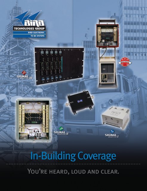
<strong>In</strong>-<strong>Building</strong> <strong>Coverage</strong><br />
You’re heard, loud and clear.
<strong>In</strong>-<strong>Building</strong> <strong>Coverage</strong><br />
Signal Boosters & Accessories<br />
table of contents<br />
Signal Boosters Legacy Technical Specifications Page 2<br />
Signal Boosters I Technical Specifications Page 4<br />
Signal Boosters Line Extender Page 7<br />
Signal Boosters II Technical Specifications Page 8<br />
Signal Booster II Remote Communication Card Page 10<br />
Signal Booster II Automatic Voice/Pager Dialer Option Page 11<br />
Signal Booster RescueL<strong>In</strong>e Page 13<br />
Channelized Booster Page 14<br />
Hybrid Directional Couplers Page 15<br />
Crossband Couplers Page 18<br />
Splitters Page 20<br />
Samplers Page 21<br />
Signal Booster Model Order Guide (SBII Family):<br />
SAMPLE ORDER: 61-65-50 Series, 406-430 MHz Signal Booster II<br />
Example Model option 1: 61-65-50-A0.8-G1 (406-430 MHz SBII, 80 dB, 800 KHz,<br />
Painted Steel NEMA 4 Housing)<br />
61-65-50-#(X.X)-XX<br />
# = Gain Designator X.X=Passband XX=Housing Option<br />
A – 80 dB (High Gain) 0.8 – 800 KHz G1 – Painted Steel NEMA 4<br />
B – 60 dB (Mid Gain) 5.0 =5 MHz G2 – Stainless Steel NEMA 4X<br />
C – 45 dB (Low Gain)<br />
RM – 19 inch Rack Mount<br />
Note: All frequencies must be provided at time of order.<br />
1<br />
tel: 866.695.4569 fax: 716.549.4772 e: sales@bird-technologies.com<br />
Bird Technologies Group RESERVES THE RIGHT TO MODIFY SPECIFICATIONS OR DISCONTINUE ANY PRODUCT<br />
WITHOUT NOTICE Terms and Conditions posted on http://www.bird-technologies.com/sales/btg_tc.pdf
Signal Boosters<br />
Technical Specifications<br />
VHF Legacy booster<br />
Model Numbers<br />
Frequency<br />
Passband<br />
bandwidth<br />
Minimum<br />
Gain<br />
Gain Adjustment<br />
3rd Order Output<br />
<strong>In</strong>tercept Point<br />
Output 1 dB<br />
Compression Point<br />
RF Sampler<br />
Noise Figure<br />
(without<br />
attenuation)<br />
Operating<br />
Temperature Range<br />
Nominal Impedance<br />
60-38-02-OLC-XX<br />
60-38-02-OLC-CF-XX<br />
60-38-02-OLC-XX<br />
60-38-02-OLC-CF-XX<br />
60-38-02-OLC-XX<br />
60-38-02-OLC-CF-XX<br />
132-174 MHz<br />
1 MHz nominal<br />
15 kHz, includes crystal<br />
filter<br />
+74 dB (see note below)<br />
+66 dB (see note below)<br />
3 and 6 dB pads<br />
+42 dBm minimum,<br />
with no attenuation<br />
+32 dBm minimum<br />
PA Output sampler<br />
ports<br />
6.5 dB maximum<br />
-30° C to +60° C<br />
50 ohms<br />
VSWR
Signal Booster<br />
Technical Specifications<br />
Uhf commercial band<br />
Frequency<br />
Passband<br />
bandwidth<br />
Minimum Gain***<br />
Gain Adjustment<br />
3rd Order Output<br />
<strong>In</strong>tercept Point<br />
Maximum <strong>In</strong>put Level<br />
Maximum Output Power<br />
RF Sampler<br />
Noise Figure (without<br />
attenuation)<br />
Propagation Delay<br />
Operating Temperature<br />
Range<br />
Nominal Impedance<br />
61-70-50-#0.5-XX<br />
61-70-50-#1.0-XX<br />
61-70-50-#2.0-XX<br />
61-71-50-#0.15-XX<br />
61-71-50-#0.5-XX<br />
61-72-50-#0.15-XX<br />
61-72-50-#0.5-XX<br />
61-70-50-#0.5-XX<br />
61-70-50-#1.0-XX<br />
61-70-50-#2.0-XX<br />
61-71-50-#0.15-XX<br />
61-71-50-#0.5-XX<br />
61-72-50-#0.15-XX<br />
61-72-50-#0.5-XX<br />
61-70-50-#2.0-XX<br />
450-470 MHz<br />
450-470 MHz<br />
450-470 MHz<br />
470-490 MHz<br />
470-490 MHz<br />
488-512 MHz<br />
488-512 MHz<br />
0.5 MHz<br />
1 MHz<br />
2 MHz<br />
150 KHz<br />
0.5 KHz<br />
150 KHz<br />
0.5 KHz<br />
+45/60/80 dB (See Note Below)<br />
0-30 dB, 0.5 dB increments<br />
+54 dBm minimum, with no attenuation<br />
0 dBm<br />
+32 dBm (single carrier)<br />
PA Output sampler ports<br />
8 dB (12 dB for low gain unit)<br />
Signal booster I<br />
62-83E-Series<br />
Dual Band 700/800 MHz<br />
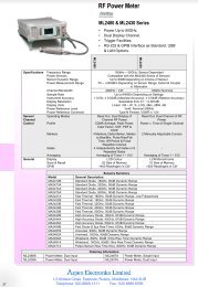
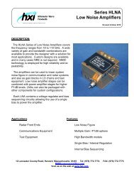
Bird Technologies Group, TX RX Systems brand, SB I Series family of signal boosters<br />
provides an exceptional balance of performance and value for extended coverage of<br />
radio communications networks.<br />
Problems<br />
RF coverage is required for different building<br />
sizes and configurations<br />
System monitoring is required<br />
Need to eliminate potential interference<br />
and unwanted coverage<br />
Reliable in-building communications is a<br />
must<br />
Need to provide coverage for both 700<br />
MHz and 800 MHz<br />
Solutions<br />
Bird SBI is available in two output power<br />
models:<br />
- High power model (+34 dBm)<br />
- Low power model (+25.5 dBm)<br />
Alarm and sampler port are available<br />
Gain is adjustable from 0 to 30 dB in 2 dB<br />
increments<br />
Bird invented the signal booster and has been a<br />
leader in providing reliable in-building wireless<br />
solutions since 1980<br />
SBI dualband provides coverage of both frequencies<br />
in one unit<br />
Applications<br />
Cost effective in-building coverage solutions for applications in critical communications systems<br />
Public Safety, Private Wireless networks<br />
Excellent selectivity for operation in a shared frequency band<br />
Specifications, Electrical<br />
Gain (Minimum attenuation) [dB] 80<br />
Gain Flatness [dB]<br />
Noise Figure [dB]<br />
Manual Attenuation Range [dB]<br />
-Gain adjustment<br />
Power Output @ 1dB<br />
Compression (P1dB) [dBm]<br />
62-83E-ADB-02-T3<br />
62-83E-ADB-04-T3<br />
+/- 1.5 (Max)<br />
5 (Max.) 4 (Typ)<br />
0 to 30 in 2-dB steps<br />
+25.5 (Min.) - Uplink, +34 (Min.) - Downlink<br />
+25.5 (Min.) - Uplink, +25.5 (Min.) - Downlink<br />
Model Options<br />
62-83E-ADB-02-T3<br />
62-83E-ADB-02-T3-ALS<br />
62-83E-ADB-04-T3<br />
62-83E-ADB-04-TS-3-ALS<br />
Low Power,<br />
Dual Band<br />
Low Power,<br />
Dual Band with<br />
Alarm & Sampler<br />
High Power,<br />
Dual Band<br />
High Power,<br />
Dual Band with<br />
Alarm & Sampler<br />
Output OLC Set [dBm]<br />
Output Composite Power [dBm]<br />
3rd Order Output <strong>In</strong>tercept<br />
Point (IP3) [dBm]<br />
<strong>In</strong>put/Output Impedance<br />
VSWR IN/OUT<br />
Power Supply<br />
Weight<br />
62-83E-ADB-02-T3<br />
62-83E-ADB-04-T3<br />
62-83E-ADB-02-T3<br />
62-83E-ADB-04-T3<br />
62-83E-ADB-02-T3<br />
62-83E-ADB-04-T3<br />
62-83E-ADB-02-T3<br />
62-83E-ADB-04-T3<br />
+25.5 (Min.) - Uplink, +34 (Min.) - Downlink<br />
+25.5 (Min.) - Uplink, +25.5 (Min.) - Downlink<br />
+25.5 (Min.) - Uplink, +34 (Min.) - Downlink<br />
+25.5 (Min.) - Uplink, +25.5 (Min.) - Downlink<br />
+25.5 (Min.) - Uplink, +34 (Min.) - Downlink<br />
+25.5 (Min.) - Uplink, +25.5 (Min.) - Downlink<br />
50 ohm<br />
1.5;1 (Max)<br />
110VAC/0.9A, 240VAC/.45A<br />
110VAC/1.4A, 240VAC/0.7A<br />
33 lbs<br />
Specifications, MECHANICal<br />
Enclosure Finish<br />
Corrosion Protection, Powder Coat (Taupe)<br />
Dimensions 15.3” x 15.4” x 7.9”<br />
Operating Temperature Range<br />
-20°C to +50°C<br />
Frequency (Dual band) UPLINK (MHz) DOWNLINK (MHz)<br />
700 MHz Band 794-806 746-776<br />
800 MHz Band 806-824 851-869<br />
tel: 866.695.4569 fax: 716.549.4772 e: sales@bird-technologies.com<br />
Bird Technologies Group RESERVES THE RIGHT TO MODIFY SPECIFICATIONS OR DISCONTINUE ANY PRODUCT 4<br />
WITHOUT NOTICE Terms and Conditions posted on http://www.bird-technologies.com/sales/btg_tc.pdf
Signal booster I<br />
62-89A-Series<br />
LMR 800 MHz<br />
Specifications, Electrical<br />
Gain Minimum attenuation [dB] 80<br />
Gain Flatness [dB]<br />
+/- 1.5 (Max)<br />
Noise Figure [dB]<br />
5 (Max)<br />
Manual Attenuation Range [dB]<br />
-Gain Adjustment<br />
Output Composite Power [dBm]<br />
3rd Order Output <strong>In</strong>tercept<br />
Point (IP3) [dBm]<br />
62-89A-A18-03-T3<br />
62-89a-a18-01-t3<br />
62-89A-A18-03-T3<br />
62-89a-a18-01-t3<br />
<strong>In</strong>put/Output Impedance<br />
VSWR IN/OUT<br />
Propagation Delay [uSec] 1.0<br />
AC Power <strong>In</strong>put<br />
Unit Power Consumption<br />
(AC/DC)<br />
1.5:1 (Max)<br />
85-265 VAC. Autoranging<br />
(47-63 Hz)<br />
45 watts<br />
tel: 866.695.4569 fax: 716.549.4772 e: sales@bird-technologies.com<br />
5<br />
Bird Technologies Group RESERVES THE RIGHT TO MODIFY SPECIFICATIONS OR DISCONTINUE ANY PRODUCT<br />
WITHOUT NOTICE Terms and Conditions posted on http://www.bird-technologies.com/sales/btg_tc.pdf<br />
Model OPtion<br />
62-89B-A03-03-T3<br />
62-89B-A03-01-T3<br />
62-89B-A03-03-T3-ALS<br />
62-89B-A03-01-T3-ALS<br />
Specifications, MECHANICal<br />
Enclosure Finish<br />
Corrosion Protection,<br />
Powder Coat (Taupe)<br />
Dimensions 15.3” x 15.4” x 7.9”<br />
Operating Temperature<br />
Range<br />
Weight<br />
806-809/851-854 MHz,<br />
80 dB, 3 MHz<br />
806-809/851-854 MHz,<br />
80 dB, 3 MHz<br />
806-809/851-854 MHz,<br />
80 dB, 3 MHz with alarm<br />
and sampler<br />
806-809/851-854 MHz,<br />
80 dB, 3 MHz with alarm<br />
and sampler<br />
62-90A-A03-03-T3 821-824/866-869 MHz, 80<br />
dB, 3 MHz<br />
62-90A-A03-01-T3 821-824/866-869 MHz, 80<br />
dB, 3 MHz<br />
62-90A-A03-01-T3-ALS<br />
62-90A-A03-03-T3-ALS<br />
BDA, 821-824/866-869 MHz,<br />
80 dB, 3 MHz with alarm<br />
and sampler<br />
BDA, 821-824/866-869 MHz,<br />
80 dB, 3 MHz with alarm<br />
and sampler<br />
-30°C to +50°C<br />
22 lbs
Bird Technologies Group, TX RX Systems brand, SB I Series family of signal boosters<br />
provides an exceptional balance of performance and value for extended coverage of<br />
radio communications networks.<br />
Signal booster I<br />
62-91A-Series<br />
Cellular A, B, & A/B Bands<br />
Problems<br />
Solutions<br />
Model Options<br />
RF coverage is required for different building<br />
sizes and configurations<br />
System monitoring is required<br />
Bird SBI is available in two output power<br />
models:<br />
- High power model (+34 dBm)<br />
- Low power model (+25.5 dBm)<br />
Alarm and sampler port are available<br />
High Power (+34 dB)<br />
62-91-A11-03-T3<br />
62-91-A11-03-T3-ALS<br />
Cell A<br />
Cell A with Alarm &<br />
Sampler<br />
Need to eliminate potential interference<br />
and unwanted coverage<br />
Reliable in-building communications is a<br />
must<br />
Need to provide coverage for both 700<br />
MHz and 800 MHz<br />
Gain is adjustable from 0 to 30 dB in 2 dB increments<br />
Bird invented the signal booster and has been a<br />
leader in providing reliable in-building wireless<br />
solutions since 1980<br />
SBI dualband provides coverage of both frequencies<br />
in one unit<br />
62-91B-A14-03-T3<br />
62-91B-A14-03-T3-ALS<br />
62-91A-A25-03-T3<br />
62-91A-A25-03-T3-ALS<br />
Cell B<br />
Cell B with Alarm &<br />
Sampler<br />
Cell A/B<br />
Cell A/B with Alarm<br />
& Sampler<br />
Applications<br />
Cost effective in-building coverage solutions for applications in critical communications systems<br />
<strong>Coverage</strong> of full Cellular A/B bands or each band individually<br />
Excellent selectivity for operation in a shared frequency band<br />
Specifications, Electrical<br />
Gain Minimum attenuation [dB] 80<br />
Gain Flatness [dB]<br />
Noise Figure [dB]<br />
Manual Attenuation Range [dB]<br />
-Gain adjustment<br />
Output Composite Power [dBm]<br />
3rd Order Output <strong>In</strong>tercept<br />
Point [dBm] @ 2 tones<br />
+22 dBm ea.<br />
<strong>In</strong>put/Output Impedance<br />
VSWR IN/OUT<br />
62-91-AXX-03-T3<br />
62-91-AXX-01-T3<br />
62-91-AXX-03-T3<br />
62-91-AXX-03-T3<br />
62-91-AXX-01-T3<br />
62-91-AXX-03-T3<br />
+/- 1.5 (max)<br />
5 (Max.)<br />
0 to 30 in 2-dB steps<br />
+25.5 (Min.) - Uplink, +34 (Min.) - Downlink<br />
+25.5 (Min.) - Uplink, +25.5 (Min.) - Downlink<br />
+45 (Typ.) - Uplink, +50 (Typ.) - Downlink<br />
+45 (Typ.) - Uplink, +45 (Typ.) - Downlink<br />
50 ohm<br />
Propagation Delay [uSec]
Signal booster I<br />
62-89A-D18-05-EXT<br />
Line Extender<br />
Bird Technologies Group, TX RX Systems brand, SB I Series family of signal<br />
boosters provides an exceptional balance of performance and value for extended<br />
coverage of radio communications networks.<br />
Problems<br />
Small component that can be used in all runs<br />
Used in bidirectional applications<br />
Optimize system<br />
Easy hookup<br />
Solutions<br />
- Compact Design<br />
- Based on a duplexed path configuration<br />
- Extends the effective range of the Signal Booster<br />
- Powered by AC/DC converter or DC via BTS port<br />
Applications<br />
Is a cost effective solution to compensate for cable losses in a Distributed Antenna Systems (DAS).<br />
Specifications, ElectrICal<br />
Model 62-89A-D18-05-EXT SMRPS8<br />
Frequency Band<br />
Gain (Minimum attenuation) [dB]<br />
Noise Figure [dB]<br />
Manual Attenuation Range [dB] -<br />
Gain adjustment<br />
<strong>In</strong>put/Output Impedance<br />
Power Supply Provided<br />
Finish<br />
Net Weight<br />
Dimensions<br />
Operating Temperature Range<br />
Connectors<br />
Linear Output Power<br />
Uplink<br />
Downlink<br />
806-869 / 851-869<br />
806-824 MHz<br />
851-869 MHz<br />
30 dB min.<br />
50 ohm<br />
5<br />
30 in 2 dB steps<br />
5VE.5A<br />
Black<br />
116 (0.454 kg)<br />
4.5”x3.325”x1.0625” (114.3x84.46x27.05 mm)<br />
-20 c to +50 c<br />
N Female<br />
-15 dBm<br />
tel: 866.695.4569 fax: 716.549.4772 e: sales@bird-technologies.com<br />
7<br />
Bird Technologies Group RESERVES THE RIGHT TO MODIFY SPECIFICATIONS OR DISCONTINUE ANY PRODUCT<br />
WITHOUT NOTICE Terms and Conditions posted on http://www.bird-technologies.com/sales/btg_tc.pdf
Signal Booster II<br />
132-941 MHz<br />
Bird Technologies Group, TX RX Systems brand, Signal Booster II bi-directional amplifiers<br />
provide Public Safety grade communications and reliability in disadvantaged RF locations<br />
for First Responders, Public Safety/Governmental agencies and Private system Users.<br />
Mission-critical communications are ensured in challenging environments such as:<br />
Basements<br />
Parking Garages<br />
Correctional Facilities<br />
Courthouses<br />
Hospitals<br />
High-rise <strong>Building</strong>s<br />
Schools & Universities<br />
Airports<br />
Subways & Rapid Transit Systems<br />
Stadiums<br />
Forward-thinking features that aid the installation include:<br />
Decoupled Test Points for Signal Level Detection<br />
Menu Driven Gain Setting<br />
Front Panel LED Status <strong>In</strong>dicators<br />
At-a-glance LED Bar Graph for Output Level Control (OLC)<br />
OLC Data Logging<br />
Output Level Control (OLC) Circuit Monitors and<br />
Controls RF Output Power<br />
Maintains maximum required output power while preventing<br />
damage and excessive emissions per FCC requirements<br />
Easy-to-read LED bar graph<br />
Unique OLC DataLog feature facilitates system<br />
maintenance and optimization<br />
Decoupled RF Test Points For Simplified Service<br />
Allow fast system measurements in both uplink and downlink<br />
directions<br />
Monitor signals for performance optimization<br />
<strong>In</strong>tegrated design facilitates non-intrusive measurements<br />
Secure, Non-Vented NEMA Enclosure Suitable for Extreme<br />
<strong>In</strong>door and Outdoor Environments<br />
Simple Setup is Achieved Via an <strong>In</strong>tegral, Man-Machine<br />
<strong>In</strong>terface<br />
No Tools Required<br />
Optional Features Available<br />
Comm Card II for remote communications and control<br />
Fiber optic link interface<br />
Redundant PA configuration<br />
-48 VDC input<br />
Voice/pager dialer<br />
DC Backup <strong>In</strong>terface Accepts +24 to +27 VDC and optional<br />
-48 VDC<br />
Microprocessor Controlled Fault Monitoring and<br />
Alarming Ensures Reliable Operation and Flexible<br />
Configuration<br />
Control system continuously monitors parameters including<br />
voltage, current, temperature and OLC activity<br />
LEDs on each module quickly annunciate source of fault<br />
Simple, back-lit liquid crystal display (LCD) and switch control<br />
Fault triggers annunciation on panel, alarm contact closure and<br />
internal recording of failed subsystem<br />
Card Cage Modularity<br />
Easy “slide-in” replacement process<br />
Facilitates ease of service and system configuration<br />
High Performance Bandpass Filters<br />
Configured to customer requirements and addresses many<br />
specifications requiring custom passbands<br />
Models available with passbands that range from 3 MHz<br />
(NPSPAC with excellent out-of-band rejection) to 18 MHz for full<br />
band coverage<br />
Programmable Gain Setting<br />
Ease of initial configuration via front panel<br />
When used in conjunction with OLC DataLog, simplifies post<br />
installation adjustments<br />
Three Major Gain Ranges Available<br />
Low:+ 45 dB, Medium:+ 60 dB, High:+ 80 dB<br />
tel: 866.695.4569 fax: 716.549.4772 e: sales@bird-technologies.com<br />
Bird Technologies Group RESERVES THE RIGHT TO MODIFY SPECIFICATIONS OR DISCONTINUE ANY PRODUCT 8<br />
WITHOUT NOTICE Terms and Conditions posted on http://www.bird-technologies.com/sales/btg_tc.pdf
Signal Booster II<br />
Technical Specifications<br />
800 MHz band<br />
Model Numbers<br />
Frequency<br />
Passband<br />
bandwidth****<br />
Minimum Gain***<br />
Gain Adjustment<br />
3rd Order Output<br />
<strong>In</strong>tercept Point<br />
Maximum <strong>In</strong>put Level<br />
Maximum Output<br />
Level<br />
RF Sampler<br />
61-89A-50-#18-XX<br />
61-89A-50-#15-XX<br />
61-89A-50-#10-XX<br />
61-89A-50-#06-XX<br />
61-89A-50-#05-XX<br />
61-89A-50-#03-XX<br />
61-89A-50-#18-XX<br />
61-89A-50-#15-XX<br />
61-89A-50-#10-XX<br />
61-89A-50-#06-XX<br />
61-89A-50-#05-XX<br />
61-89A-50-#03-XX<br />
806-869 MHz;<br />
18 MHz<br />
15 MHz<br />
10 MHz<br />
6 MHz<br />
5 MHz<br />
3 MHz<br />
+45/60/80 dB<br />
(See Note Below)<br />
Programmable 0-30 dB,<br />
0.5 dB increments<br />
+55 dBm minimum,<br />
with no attenuation<br />
0 dBm<br />
+30 dBm<br />
(single carrier)<br />
PA Output sampler ports<br />
Noise Figure<br />
6.5 dB maximum<br />
(without<br />
attenuation)<br />
Propagation Delay
Signal Booster II<br />
Remote Communication Card<br />
Model 6150-COM<br />
Adds Complete Remote Accessibility to Signal Booster II<br />
Remote configuration and gain level adjustment<br />
Remote retrieval of 100 day OLC Datalog information<br />
Remote alarm and status monitoring<br />
Remote loading of software updates, revisions<br />
Data Ports: RS232 Port accommodates direct connection to local PC.<br />
RJ45 Port provides 10 Base T interface to private networks, internet or wireless (WiFi) networks.<br />
TCP/IP Network Protocol Compatibility Static or DHCP assigned IP address.<br />
HTTP 1.0/1.1 web compatible provides complete functionality using common web browsers.<br />
Currently supports FTP firmware update, email alert feature available in future software release.<br />
No PC Based Proprietary Software Required - Uses Common Web Browser<br />
Remote Configuration of Critical Operating<br />
Parameters<br />
Calibrate amplifier current to eliminate erroneous alarms<br />
Adjust gain via attenuation or bypass amplifiers when OLC<br />
datalog indicates consistent, strong signal activity through<br />
booster<br />
Configure desired output power<br />
Remote Access to Critical Component Status<br />
Amplifier Cards<br />
Power Amps<br />
Power System<br />
Output Level Control System<br />
Remote Access to OLC (Output Level Control) Datalog<br />
Access operational history for critical parameter adjustment<br />
Data exportable in text file format<br />
Datalog resolution can be as fine as hourly or as long as 100<br />
days in duration. Consult factory for optional configurations<br />
tel: 866.695.4569 fax: 716.549.4772 e: sales@bird-technologies.com<br />
Bird Technologies Group RESERVES THE RIGHT TO MODIFY SPECIFICATIONS OR DISCONTINUE ANY PRODUCT 10<br />
WITHOUT NOTICE Terms and Conditions posted on http://www.bird-technologies.com/sales/btg_tc.pdf
Signal Booster II<br />
Automatic Voice/Pager Dialer Option<br />
Model 6150-Page<br />
Another remote accessibility option to Signal Booster II<br />
Provides reliable emergency notification 24 hours a day<br />
Ideal for installations where Ethernet connection is not available, so that the Remote<br />
Communication Card cannot be used<br />
Stand-alone AD-2000 Dialer with dry-contact interface to SBII<br />
Extensively programmable, offering personalized customization<br />
Bird Technologies Group, TX RX Systems brand, 6150-PAGE automatic dialer<br />
features busy-line and no-answer detection to ensure prompt transmission of<br />
up to 4 prerecorded messages delivered sequentially to as many as 8 standard<br />
telephones, cellular phones, voice and/or numeric pagers. Messages to both local<br />
and long-distance calls can be transmitted. When activated, the dialer instantly<br />
begins calling the numbers in sequence, delivering each message 1 to 3 times in a<br />
row, in accordance with the pre-selected number of dialing attempts. Plain-English<br />
prompts walk the user through the programing process in a timely manner.<br />
PROGRAMMING OPTIONS:<br />
Store up to 8 telephone/pager numbers.<br />
Choose 1- 9 calling efforts for the numbers dialed.<br />
Select 1-3 message repeats.<br />
Record a variable combination (maximum: 7) of instructional outgoing messages (total elapsed time: 51 seconds).<br />
Program up to 4 separate input channels with individually enable/disable, entry/exit delay and activation options - Normally Open (N.O.),<br />
Normally Closed (N.C.), including momentary and continuous activation for each.<br />
Further individualize each channel by selecting the delay times, telephone/pager numbers to be dialed and the specific outgoing<br />
messages to be played.<br />
tel: 866.695.4569 fax: 716.549.4772 e: sales@bird-technologies.com<br />
11<br />
Bird Technologies Group RESERVES THE RIGHT TO MODIFY SPECIFICATIONS OR DISCONTINUE ANY PRODUCT<br />
WITHOUT NOTICE Terms and Conditions posted on http://www.bird-technologies.com/sales/btg_tc.pdf
Signal Booster II<br />
Redundant PA Configuration<br />
Please Consult Factory<br />
Adds another reliability feature to Signal Booster II<br />
Automatically switches between Primary PA and Secondary PA<br />
Automatically goes into “bypass” mode if both PA fail<br />
PA status available from LED and front panel LCD screen<br />
User can manually switch between the two PA<br />
No impact on overall system specification<br />
Compatible with other SBII features such as Remote Comm Card and Pager options<br />
For customers of SBII with mission critical applications, the Redundant Power Amp option is<br />
yet another reliability feature we provide to ensure the uninterrupted in-building RF coverage.<br />
Our standard SBII unit already offers top-notch public-safety rated performance with stateof-the-art<br />
monitoring and alarming capabilities, and this new Redundant PA option brings<br />
another tool into our offering mix (with existing options such as 48 VDC hookup and Remote<br />
Communications Card) to satisfy the most demanding operational requirements.<br />
tel: 866.695.4569 fax: 716.549.4772 e: sales@bird-technologies.com<br />
Bird Technologies Group RESERVES THE RIGHT TO MODIFY SPECIFICATIONS OR DISCONTINUE ANY PRODUCT 12<br />
WITHOUT NOTICE Terms and Conditions posted on http://www.bird-technologies.com/sales/btg_tc.pdf
RESCUELINE Signal Booster<br />
800 MHz Series<br />
Bird Technologies Group, TX RX Systems brand, RescueLine Signal Booster, the first such signal-booster<br />
system that fully complies with the IFC 2009 and NFPA 1 2009 codes which makes it the state-of-theart<br />
electronic lifeline for first responders inside a new building. To comply with the new <strong>In</strong>ternational Fire<br />
Code and National Fire Protection Association (IFC/NFPA) standards, the Bird RescueLine delivers on a key<br />
objective: ensuring that first responders have reliable radio communications in large structures. It features<br />
a 12-hour battery back-up and an alarm interface providing all five required alarm conditions, including<br />
antenna system failure (up or down link) and 70-percent low battery. The Bird RescueLine is compatible with<br />
standard fire-alarm panels.<br />
Problems<br />
Must be compliant with IFC/NFPA Codes<br />
Solutions<br />
- NEMA 4 cabinets<br />
- Signal booster malfunction alarm<br />
- AC/DC fail alarm<br />
- Low battery alarm<br />
- Antenna Circuit malfunction<br />
- Supervised alarm Circuits<br />
- Fire alarm compatability<br />
- 12 hour battery option<br />
Applications<br />
Valued for its ability to allow public-safety personnel to communicate<br />
during critical events even while power is unavailable<br />
Delivers life-critical in-building radio communications in challenging<br />
environments<br />
Output Level Control (OLC) Circuit Monitors and Controls RF<br />
Output Power<br />
Maintains maximum required output power while preventing damage<br />
and excessive emissions per FCC requirements<br />
Easy-to-read LED bar graph<br />
Unique OLC DataLog feature facilitates system maintenance and<br />
optimization<br />
Decoupled RF Test Points For Simplified Service<br />
Allow fast system measurements in both uplink and downlink directions<br />
Monitor signals for performance optimization<br />
<strong>In</strong>tegrated design facilitates non-intrusive measurements<br />
Secure, Non-Vented NEMA Enclosure Suitable for Extreme<br />
<strong>In</strong>door and Outdoor Environments<br />
Simple Setup is Achieved Via an <strong>In</strong>tegral, Man-Machine <strong>In</strong>terface<br />
No Tools Required<br />
Optional Features Available<br />
Comm Card II for remote communications and control<br />
Fiber optic link interface<br />
Redundant PA configuration<br />
-48 VDC input<br />
DC Backup <strong>In</strong>terface Accepts +24 to +27 VDC and optional -48 VDC<br />
Microprocessor Controlled Fault Monitoring and Alarming<br />
Ensures Reliable Operation and Flexible Configuration<br />
Control system continuously monitors parameters including voltage,<br />
current, temperature and OLC activity<br />
LEDs on each module quickly annunciate source of fault<br />
Simple, back-lit liquid crystal display (LCD) and switch control<br />
Fault triggers annunciation on panel, alarm contact closure and internal<br />
recording of failed subsystem<br />
Card Cage Modularity<br />
Easy “slide-in” replacement process<br />
Facilitates ease of service and system configuration<br />
High Performance Bandpass Filters<br />
Configured to customer requirements and addresses many specifications<br />
requiring custom passbands<br />
Models available with passbands that range from 3 MHz (NPSPAC with<br />
excellent out-of-band rejection) to 18 MHz for full band coverage<br />
Programmable Gain Setting<br />
Ease of initial configuration via front panel<br />
When used in conjunction with OLC DataLog, simplifies post installation<br />
adjustments<br />
SPECIFICATION<br />
Frequency 806-869 MHz<br />
Nominal Gain***<br />
+80 dB<br />
Gain Adjustment<br />
Programmable attenuation, 0-30 dB,<br />
0.5 dB steps<br />
Output Level Control Dynamic 60 dB<br />
Range<br />
3rd Order Output <strong>In</strong>tercept Point<br />
Maximum <strong>In</strong>put Level<br />
Maximum Output Level<br />
RF Sampler<br />
Noise Figure (without attenuation)<br />
+55 dBm minimum, with no attenuation<br />
0 dBm<br />
Propagation Delay
Channelized Signal Booster<br />
611-70-Series<br />
Bird Technologies Group (BTG), TX RX Systems Channelized Signal Booster<br />
operates in the 450-512 MHz range available in 1-30+ channels. <strong>In</strong>tuitive user<br />
interface allows booster to be easily configured for changing RF environments.<br />
Channel bandwidth is user selectable (12.5, 25, and 50 kHz standard or custom).<br />
Tone squelch capability is also available and individually configured per channel.<br />
Problems<br />
Noise and <strong>In</strong>terference that cause<br />
communication problems in a<br />
crowded spectrum.<br />
Changes in RF environment.<br />
System coverage is difficult to assess.<br />
Solutions<br />
- Channelized booster amplifies narrow<br />
band channels. Amplifying only the<br />
desired spectrum prevents interference<br />
to other users.<br />
- Modular design facilitates fast and<br />
easy reconfiguration, expansion, and<br />
redundant capability. User interface<br />
also provides maximum flexibility to<br />
implement changes to the system<br />
such as output power, center frequency,<br />
filter shape, and group delay.<br />
- Built-in test signal capability allows<br />
simple verification of booster coverage.<br />
The 1kHz FM modulated carrier<br />
allows simple SINAD qualification<br />
testing.<br />
applications<br />
The Channelized booster provides Public Safety grade reliability and coverage<br />
in challenging disadvantaged RF conditions.<br />
Use as head end booster for a system that is donored “off the air” in an RF<br />
congested area<br />
One channelized booster can connect to any number of broadband boosters<br />
(SBII or SBI)<br />
Minimizes noise and interference potential in urban RF congested areas<br />
OPTIONS<br />
Channels 1-30+<br />
High power<br />
+39.5 dBm maximum per channel*<br />
Hybrid Combining or Cavity Combining for higher power out<br />
Higher Sensitivity on downlink<br />
Filtering/Duplexing<br />
Form-C summed alarm contacts either NO or NC<br />
(already standard on uplink)<br />
-75 dBm in for full output instead<br />
of -57 dBm<br />
3 MHz, 1 MHz, 0.5 MHz or custom<br />
<strong>In</strong>ternally generated high accuracy reference for very narrow (6.25 kHz)<br />
channels and filters<br />
*Note: FCC Rules limit per-channel ERP to 5 watts. Standard hybrid combining provided will<br />
reduce actual output power to 5 watts or less.<br />
OPERATING CHARACTERISTICS<br />
Frequency Range 450-512 MHz<br />
Number of Carriers<br />
per Channel Module<br />
Channel Bandwidth<br />
Output Power per<br />
Channel (Uplink/<br />
Downlink)<br />
Maximum <strong>In</strong>put<br />
Level<br />
RF <strong>In</strong>put/Output<br />
impedance<br />
External RF<br />
Connectors<br />
Alarms<br />
Control & monitoring<br />
Power<br />
Operating<br />
Temperature Range<br />
Size**<br />
Weight**<br />
1 uplink,<br />
1 downlink<br />
Programmable standard<br />
filters include 12.5 kHz,<br />
25 kHz, 50 kHz. Other<br />
custom filters can be<br />
programmed by the user<br />
or factory to meet specific<br />
system requirements.<br />
+17 dBm maximum<br />
dependent on system<br />
configurations (0.1 watts)<br />
nominal with min. -75<br />
dBm <strong>In</strong>put<br />
-12 dBm maximum,<br />
dependent on system<br />
configuration<br />
50 Ohms<br />
N - Female<br />
Form-C Contacts,<br />
Channel Module LED’s<br />
Web host via ethernet<br />
connection<br />
90-250 VAC, 50/60 Hz or<br />
27.5-29 VDC (±5%)<br />
-30 °C to +60 °C<br />
19” Rack Mount, 7 RU<br />
(12.25 in.) x 30 in. deep<br />
90 lbs<br />
**Based on configuration for 5 channel modules<br />
power supply and control card. Excludes duplexers<br />
and combiners.<br />
tel: 866.695.4569 fax: 716.549.4772 e: sales@bird-technologies.com<br />
Bird Technologies Group RESERVES THE RIGHT TO MODIFY SPECIFICATIONS OR DISCONTINUE ANY PRODUCT 14<br />
WITHOUT NOTICE Terms and Conditions posted on http://www.bird-technologies.com/sales/btg_tc.pdf
Hybrid Directional Coupler<br />
Bird Technologies Group, TX RX Systems brand has the most comprehensive line of Hybrid<br />
Directional Couplers for power division and signal distribution applications. The broad<br />
array of splits facilitates balanced signal distribution in the most comprehensive systems.<br />
Additionally, the Tri-Band products allow multi-band signal distribution via a single transmission<br />
line where multi-agency communication systems are required. They largely eliminate<br />
the near-far problem and maximize the cost-efficiency of the signal boosters. Bi-directional<br />
nature of the couplers allows them to be used for two-way communications with minimal loss<br />
above the desired coupling value.<br />
Alodine Gold finish<br />
Silver plated N female connectors with gold plated pins<br />
Multiple load configurations (no load, 5W, or 25W) available for different power requirements<br />
85-83-xx<br />
86-58-xx<br />
85-38-xx<br />
VHF, UHF & 800 MHz Harmonic<br />
144 - 174 MHz, 450 - 530 MHz, 806 - 890 MHz<br />
Deoupled<br />
Value (dB)<br />
Thruline<br />
Loss (dB)<br />
Power Ratio<br />
Thruline vs.<br />
Decoupled Ports<br />
5-Watt Load 25-Watt Load Load Deleted Dimensions (in.)<br />
Model No. (2.8 lbs.) Model No. (3.2 lbs.) Model No. (2.6 lbs.) “A” “B”<br />
-3.0 ± 0.7 dB -3.0 ± 0.3 dB 50%/50% 85-05-01 85-05-0101 85-05-01-LT 18.5 17.875<br />
-4.8 ± 0.7 dB -1.8 ± 0.3 dB 67%/33% 85-05-02 85-05-0201 85-05-02-LT 18.5 17.875<br />
-6.0 ± 0.7 dB -1.2 ± 0.3 dB 75%/25% 85-05-03 85-05-0301 85-05-03-LT 18.5 17.875<br />
-7.0 ± 1.0 dB -1.0 ± 0.2 dB 80%/20% 85-05-04 85-05-0401 85-05-04-LT 18.5 17.875<br />
-10.0 ± 1.0 dB -0.5 ± 0.2 dB 90%/10% 85-05-05 85-05-0501 85-05-05-LT 18.5 17.875<br />
-15.0 -0.2 97%/3% 85-05-06 85-05-0601 85-05-06-LT 18.5 17.875<br />
-20.0 -0.2 99%/1% 85-05-07 85-05-0701 85-05-07-LT 18.5 17.875<br />
-30.0 -0.2 99.9%/0.1% 85-05-08 85-05-0801 85-05-08-LT 18.5 17.875<br />
132 - 174 MHz<br />
Deoupled<br />
Value (dB)<br />
Thruline<br />
Loss (dB)<br />
Power Ratio<br />
Thruline vs.<br />
Decoupled Ports<br />
5-Watt Load 25-Watt Load Load Deleted Dimensions (in.)<br />
Model No. (2.8 lbs.) Model No. (3.2 lbs.) Model No. (2.6 lbs.) “A” “B”<br />
-3.0 ± 0.7 dB -3.0 ± 0.3 dB 50%/50% 85-38-01 85-38-0101 85-38-01-LT 18.5 17.875<br />
-4.8 ± 0.7 dB -1.8 ± 0.3 dB 67%/33% 85-38-02 85-38-0201 85-38-02-LT 18.5 17.875<br />
-6.0 ± 0.7 dB -1.2 ± 0.3 dB 75%/25% 85-38-03 85-38-0301 85-38-03-LT 18.5 17.875<br />
-7.0 ± 1.0 dB -1.0 ± 0.2 dB 80%/20% 85-38-04 85-38-0401 85-38-04-LT 18.5 17.875<br />
-10.0 ± 1.0 dB -0.5 ± 0.2 dB 90%/10% 85-38-05 85-38-0501 85-38-05-LT 18.5 17.875<br />
350 - 520 MHz<br />
Deoupled<br />
Value (dB)<br />
Thruline<br />
Loss (dB)<br />
Power Ratio<br />
Thruline vs.<br />
Decoupled Ports<br />
5-Watt Load 25-Watt Load Load Deleted Dimensions (in.)<br />
Model No. (2.8 lbs.) Model No. (3.2 lbs.) Model No. (2.6 lbs.) “A” “B”<br />
-3.0 ± 0.7 dB -3.0 ± 0.3 dB 50%/50% 85-58-01 85-58-0101 85-58-01-LT 9.0 8.375<br />
-4.8 ± 0.7 dB -1.8 ± 0.3 dB 67%/33% 85-58-02 85-58-0201 85-58-02-LT 9.0 8.375<br />
-6.0 ± 0.7 dB -1.2 ± 0.3 dB 75%/25% 85-58-03 85-58-0301 85-58-03-LT 9.0 8.375<br />
-7.0 ± 1.0 dB -1.0 ± 0.2 dB 80%/20% 85-58-04 85-58-0401 85-58-04-LT 9.0 8.375<br />
-10.0 ± 1.0 dB -0.5 ± 0.2 dB 90%/10% 85-58-05 85-58-0501 85-58-05-LT 9.0 8.375<br />
-15.0 ± 1.0 dB -0.3 max. 97%/3% 85-58-06 85-58-0601 85-58-06-LT 9.0 8.375<br />
-20.0 ± 1.0 dB -0.3 max. 99%/1% 85-58-07 85-58-0701 85-58-07-LT 9.0 8.375<br />
-30.0 ± 1.0 dB -0.3 max. 99.9%/0.1% 85-58-08 85-58-0801 85-58-08-LT 9.0 8.375<br />
tel: 866.695.4569 fax: 716.549.4772 e: sales@bird-technologies.com<br />
15<br />
Bird Technologies Group RESERVES THE RIGHT TO MODIFY SPECIFICATIONS OR DISCONTINUE ANY PRODUCT<br />
WITHOUT NOTICE Terms and Conditions posted on http://www.bird-technologies.com/sales/btg_tc.pdf
Hybrid Directional Coupler<br />
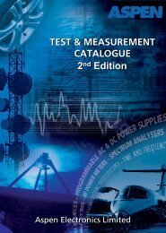
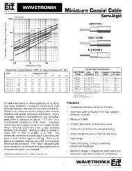
1 -12.6 dB<br />
2 -15.8 dB<br />
50’ (-1.1 dB)<br />
-3 dB<br />
200’ (-4.3 dB)<br />
SIGNAL<br />
BOOSTER<br />
UL<br />
DL<br />
150’ (-3.3 dB)<br />
RF LOSS FROM EACH ANTENNA TO SIGNAL BOOSTER<br />
IS SHOWN NEXT TO THE ANTENNA NUMBER<br />
100’ (-2.2 dB)<br />
-3 dB<br />
5 -20.3 dB<br />
150’ (-3.3 dB)<br />
200’ (-4.3 dB)<br />
-16.0 dB 4<br />
70’ (-1.5 dB)<br />
-3 dB<br />
3<br />
-12.6 dB -3 dB<br />
50’ (-1.1 dB)<br />
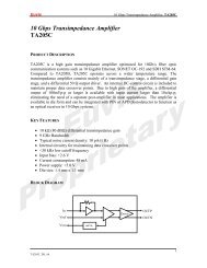
Example of An <strong>In</strong>-<strong>Building</strong> Distribution Network, with Splitters Only<br />
Numbers along the cable paths indicate signal levels relative to output of the booster: the farther the antenna is away from the booster, the<br />
lower the signal level<br />
Signals from the portables at the far-away antennas will be overwhelmed by signals at the near antennas<br />
System dynamic range is reduced with possible damage to signal booster amps<br />
System coverage is reduced with possible need for additional in-line boosters<br />
System coverage is not uniform throughtout the facility<br />
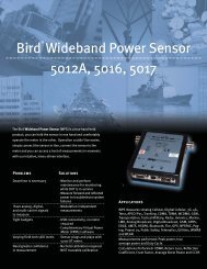
1 -16.2 dB<br />
50’ (-1.1 dB)<br />
2 -16.4 dB<br />
85-83-02<br />
200’ (-4.3 dB)<br />
SIGNAL<br />
BOOSTER<br />
DL<br />
150’ (-3.3 dB)<br />
RF LOSS FROM EACH ANTENNA TO SIGNAL BOOSTER<br />
IS SHOWN NEXT TO THE ANTENNA NUMBER<br />
UL<br />
100’ (-2.2 dB)<br />
85-83-02<br />
5 -15.3 dB<br />
150’ (-3.3 dB)<br />
-15.8 dB<br />
4<br />
200’ (-4.3 dB)<br />
70’ (-1.5 dB)<br />
85-83-03<br />
85-83-04<br />
3<br />
-15.4 dB<br />
50’ (-1.1 dB)<br />
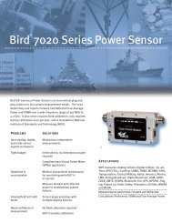
Same <strong>In</strong>-<strong>Building</strong> Distribution Network, with Couplers<br />
Signal levels are all within 3 dB regardless of the locations of the antennas<br />
System dynamic range is preserved<br />
System coverage is optimized, less likely to need in-line boosters<br />
System coverage is much more uniform throughout the facility<br />
xx: Termination Designator. No designator: 5W termination; 01: 25W termination;<br />
LT: no termination (customer can buy larger loads for higher power applications).<br />
tel: 866.695.4569 fax: 716.549.4772 e: sales@bird-technologies.com<br />
Bird Technologies Group RESERVES THE RIGHT TO MODIFY SPECIFICATIONS OR DISCONTINUE ANY PRODUCT 16<br />
WITHOUT NOTICE Terms and Conditions posted on http://www.bird-technologies.com/sales/btg_tc.pdf
Hybrid Directional Coupler<br />
746 - 960 MHz<br />
Deoupled<br />
Value (dB)<br />
Thruline<br />
Loss (dB)<br />
Power Ratio<br />
Thruline vs.<br />
Decoupled Ports<br />
5-Watt Load 25-Watt Load Load Deleted Dimensions (in.)<br />
Model No. (2.8 lbs.) Model No. (3.2 lbs.) Model No. (2.6 lbs.) “A” “B”<br />
-3.0 ± 0.7 dB -3.0 ± 0.3 dB 50%/50% 85-83-01 85-83-0101 85-83-01-LT 6.5 5.875<br />
-4.8 ± 0.7 dB -1.8 ± 0.3 dB 67%/33% 85-83-02 85-83-0201 85-83-02-LT 6.5 5.875<br />
-6.0 ± 0.7 dB -1.2 ± 0.3 dB 75%/25% 85-83-03 85-83-0301 85-83-03-LT 6.5 5.875<br />
-7.0 ± 1.0 dB -1.0 ± 0.2 dB 80%/20% 85-83-04 85-83-0401 85-83-04-LT 6.5 5.875<br />
-10.0 ± 1.0 dB -0.5 ± 0.2 dB 90%/10% 85-83-05 85-83-0501 85-83-05-LT 6.5 5.875<br />
-15.0 -0.2 97%/3% 85-83-06 85-83-0601 85-83-06-LT 6.5 5.875<br />
-20.0 -0.2 99%/1% 85-83-07 85-83-0701 85-83-07-LT 6.5 5.875<br />
-30.0 -0.2 99.9%/0.1% 85-83-08 85-83-0801 85-83-08-LT 6.5 5.875<br />
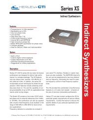
“A”<br />
“B”<br />
.875<br />
1.921<br />
Port 3<br />
Decoupled Output<br />
Coupler Configured As A<br />
Power Divider/Splitter<br />
5 Watt Load, Standard<br />
(60 Watt Resistor with Minimum<br />
Heatsink) Larger Loads may be<br />
Cabled to Coupler, to Handle<br />
Large Reflected Power<br />
Port 4<br />
Load<br />
1.250<br />
1.063<br />
Decoupled<br />
Port<br />
Port 1<br />
Common <strong>In</strong>put<br />
Thruline<br />
Port 2<br />
Thruline Output<br />
.265 DIA.,<br />
4-PLACES<br />
Port 3<br />
TX <strong>In</strong>put<br />
Coupler Configured As A<br />
Transmitter Combiner<br />
Port 4<br />
5 Watt Load, but when coupler<br />
is used as a combiner, the load<br />
size should equal or exceed<br />
transmitter output power.<br />
Larger loads may be cabled<br />
to coupler, to handle large<br />
reflected power.<br />
Decoupled<br />
Port<br />
Thruline<br />
Port 1<br />
Common Combined<br />
Output<br />
Port 2<br />
TX <strong>In</strong>put<br />
tel: 866.695.4569 fax: 716.549.4772 e: sales@bird-technologies.com<br />
17<br />
Bird Technologies Group RESERVES THE RIGHT TO MODIFY SPECIFICATIONS OR DISCONTINUE ANY PRODUCT<br />
WITHOUT NOTICE Terms and Conditions posted on http://www.bird-technologies.com/sales/btg_tc.pdf
Crossband Couplers<br />
25-960 MHz<br />
Bird Technologies Group, TX RX Systems brand, Crossband Couplers allow multiband<br />
operation of tower transmission lines, reducing cost and tower loading. They<br />
are designed for transmit or receive operations with DC pass-thru models or tower<br />
mount Rx Systems. Models are available for specialized transmit and receive applications.<br />
Complete response curves are available on request.<br />
Tunable capacitors are replaced with large area transmission line structure for greater<br />
reliability.<br />
Cascading certain models will allow three frequency bands to use one transmission<br />
line.<br />
Tower mount models consist of the base station unit, less rack bar, in a weatherproof<br />
fiberglass housing which is sealed with silicone rubber adhesive.<br />
base station mount<br />
weatherproof tower mount<br />
MODEL NUMBER<br />
WEATHERPROOF BASE STATION<br />
FREQUENCY BANDS<br />
COUPLED (MHz)<br />
TOWER MOUNT MOUNT<br />
80-05-01 80-05-02 406-512 MHz<br />
806-960 MHz<br />
80-05-03 80-05-02 406-512 MHz<br />
806-960 MHz<br />
80-05-04 80-05-05 406-512 MHz<br />
806-960 MHz<br />
80-05-07 80-05-06 25-175 MHz<br />
406-960 MHz<br />
80-05-09 80-05-08 25-175 MHz<br />
406-960 MHz<br />
80-05-10 --- 406-512 MHz<br />
806-960 MHz<br />
TYPICAL<br />
LOSS (dB)<br />
0.20<br />
0.20<br />
0.30<br />
0.50<br />
0.30<br />
0.50<br />
0.25<br />
0.25<br />
0.30<br />
0.50<br />
0.30<br />
0.35<br />
ISOLATION<br />
(dB)<br />
POWER RATING<br />
WATTS<br />
40 750<br />
500<br />
40 Receive Only 1<br />
40 250<br />
Receive Only<br />
2<br />
40 250<br />
350<br />
40 Receive Only 3<br />
40 Receive Only 4<br />
SEE NOTES<br />
BELOW<br />
COMMON SPECIFICATIONS<br />
Temperature Range<br />
-40º to +70ºC<br />
VSWR (50 ohm ref.) 1.25:1<br />
Connectors<br />
‘N’ female<br />
Dimensions HxWxL [inches (mm)]<br />
Weatherproof Models: 3.5 x 6 x 13.75<br />
Base Station Models: 2 x 19 x 3<br />
NOTES:<br />
1. 80-05-03 will pass DC power between center conductors of all three terminals for operating separate Tower Mount receive systems.<br />
2. DC will pass only between the transmission line terminal and the 800 MHz terminal for operating an 800 MHz Receive Tower Mount<br />
preamplifier. The UHF branch contains a series high current input capacitor to block DC and pass transmit power.<br />
3. DC power passes through UHF and is blocked from VHF to antenna terminal.<br />
4. DC power passes through UHF and is blocked from 800 MHz to antenna terminal.<br />
tel: 866.695.4569 fax: 716.549.4772 e: sales@bird-technologies.com<br />
Bird Technologies Group RESERVES THE RIGHT TO MODIFY SPECIFICATIONS OR DISCONTINUE ANY PRODUCT 18<br />
WITHOUT NOTICE Terms and Conditions posted on http://www.bird-technologies.com/sales/btg_tc.pdf
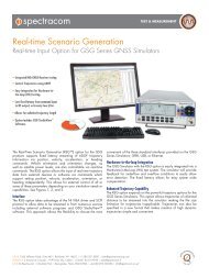
CrossBand Couplers<br />
Typical Applications<br />
I. UHF/800 MHz Tx or Rx USE<br />
(NO DC POWER TRANSFER)<br />
II. UHF/800 MHz TOWER MOUNTS<br />
UHF<br />
800 MHz<br />
80-05-01<br />
UHF<br />
PREAMP<br />
800 MHz-<br />
PREAMP<br />
80-05-03<br />
80-05-02<br />
BIAS INJECTOR<br />
UHF<br />
SYSTEM<br />
800 MHz<br />
SYSTEM<br />
DC<br />
80-05-02<br />
III. UHF TRANMIT/800 MHz Rx TOWER MOUNT<br />
UHF<br />
800 MHz<br />
PREAMP<br />
UHF<br />
RECEIVER<br />
MULTICOUPLER<br />
IV. VHF/UHF/800 MHz<br />
800 MHz<br />
RECEIVER<br />
MULTICOUPLER<br />
UHF<br />
800 MHz<br />
80-05-04<br />
VHF<br />
80-05-01<br />
80-05-07<br />
80-05-05<br />
80-05-06<br />
UHF<br />
REPEATER<br />
DC<br />
BIAS INJECTOR<br />
80-05-02<br />
800 MHz<br />
RECEIVER<br />
MULTICOUPLER<br />
VHF<br />
UHF<br />
800 MHz<br />
<strong>In</strong> this configuration,<br />
passing DC for Tower<br />
Mount Preamp is not<br />
a standard option.<br />
tel: 866.695.4569 fax: 716.549.4772 e: sales@bird-technologies.com<br />
19<br />
Bird Technologies Group RESERVES THE RIGHT TO MODIFY SPECIFICATIONS OR DISCONTINUE ANY PRODUCT<br />
WITHOUT NOTICE Terms and Conditions posted on http://www.bird-technologies.com/sales/btg_tc.pdf
Splitters<br />
Bird Technologies Group, TX RX Systems brand, power dividers are grouped into Hybrid/<br />
Wilkensen and Stripline/coaxial designs. Hybrid designs are characterized by port-to-port isolation<br />
of 20 dB or more and are typically used in receiver multicoupler or low power signal booster<br />
applications. Stripline splitters have no port-to-port isolation and are most typically used to feed<br />
transmitter power to multiple antennas for phased arrays or similar applications. The models<br />
below are characterized by low-loss above the splitting loss and wide bandwidths. N connectors<br />
are standard.<br />
84-01-11<br />
Can cover VHF and UHF, or 800-900 MHz bands.<br />
Two types of construction for different types of applications.<br />
Model<br />
Number<br />
Frequency<br />
Range (MHz)<br />
Number of Outputs<br />
(X-way splitter)<br />
Power Rating<br />
(<strong>In</strong>put)<br />
<strong>In</strong>sertion<br />
Loss<br />
Ratio of<br />
Output/<strong>In</strong>put<br />
Connectors<br />
84-01-09* 10-512 2 125 W -3.2 dB 50% N male<br />
84-01-11 25-512 2 Rx only -3.2 dB 50% N male<br />
84-01-12 25-512 4 Rx only -6.4 dB 25% N female<br />
84-01-12<br />
84-37-01* 144-174 2 800 W -3.2 dB 50% N female<br />
84-37-02 144-174 4 1000 W -6.4 dB 25% N female<br />
84-58-01* 350-520 2 800 W -3.2 dB 50% N female<br />
84-58-02 350-520 4 1000 W -6.4 dB 25% N female<br />
84-83-01 746-960 2 Rx only -3.2 dB 50% N female<br />
84-83-02 746-960 4 Rx only -6.4 dB 25% N female<br />
84-83-12 746-960 3 500 W -5.1 dB 33% N female<br />
84-01-13<br />
84-83-14 746-960 2 500 W -3.2 dB 50% N female<br />
84-83-17 746-960 4 500 W -6.4 dB 25% N female<br />
* Coated version available. Add “C” at the end of the model number, e.g. 84-01-09C<br />
tel: 866.695.4569 fax: 716.549.4772 e: sales@bird-technologies.com<br />
Bird Technologies Group RESERVES THE RIGHT TO MODIFY SPECIFICATIONS OR DISCONTINUE ANY PRODUCT 20<br />
WITHOUT NOTICE Terms and Conditions posted on http://www.bird-technologies.com/sales/btg_tc.pdf
Samplers<br />
Bird Technologies Group, TX RX Systems brand, signal samplers are non-directional taps for<br />
sampling RF signals from a main transmission line, with minimal effect to the power level of<br />
the signals on the main line. The sampled port can be connected to a Spectrum Analyzer for<br />
analysis and measurement, or connected to a low gain, distribution antenna in Signal Boosters<br />
systems to augment communications in buildings and tunnels. We offer a broad range of sampling<br />
levels to accommodate a wide variety of applications.<br />
Signal samplers are used to check system performance while in-use.<br />
Extremely low insertion loss with sample values of 20, 30, 40 and 50 dB.<br />
84-xx-xx-01<br />
Model Number Frequency Range Coupling Loss Power Split Ratio VSWR* Power Rating<br />
[ThrulineSampled] [Thruline/<br />
84-38-10-xx 132-174 MHz<br />
ed]<br />
-0.9/-10 dB<br />
Sampled]<br />
10/90 %
tel: 866.695.4569 fax: 716.549.4772 e: sales@bird-technologies.com<br />
Bird Technologies Group RESERVES THE RIGHT TO MODIFY SPECIFICATIONS OR DISCONTINUE ANY PRODUCT 22<br />
WITHOUT NOTICE Terms and Conditions posted on http://www.bird-technologies.com/sales/btg_tc.pdf
Bird® Technologies Group (BTG) is a global, innovative supplier<br />
of RF products, systems, services and educational solutions.<br />
Combining the industry leading brands of both Bird Electronic<br />
and TX RX Systems in one company reinforces the BTG<br />
commitment to providing RF Measurement and Management in<br />
Your World.<br />
Our portfolio includes hardware, software, components and services. We<br />
offer these innovative products and services through our industry leading<br />
product line brands, Bird Electronic Corp and TX RX Systems. We<br />
provide test instruments that are highly accurate, rugged and easy to<br />
use. <strong>In</strong>dustry leading components and products such as site analyzers,<br />
wattmeters, digital sensors, samplers, antennas, signal boosters,<br />
and tower mounted amplifiers. Furthermore, we offer dependable<br />
engineering, calibration and educational services for land mobile radio,<br />
cellular, semiconductor, broadcast, medical, military and government<br />
applications.<br />
All BTG products can be serviced and calibrated by the Bird Service<br />
Center (BSC). BSC provides a full range of service and support. With over<br />
130 years of combined product and calibration experience, our service<br />
technicians and product experts offer reliable service and customer care.<br />
Bird Service Centers and Service Partners are located World Wide<br />
providing a full range of service and support for your Bird Products.<br />
Catalogs offered by Bird Technologies Group<br />
(To view or download go to www.bird-technologies.com)<br />
Bird General Catalog<br />
RF & Microwave Components Catalog<br />
Transmit Combiners Catalog<br />
Cavity Filters & Duplexers Catalog<br />
Antennas Catalog<br />
Tower Top Amplifiers, Receiver Multicouplers & Preselectors Catalog<br />
Isolators & Loads Catalog<br />
<strong>In</strong>-<strong>Building</strong> <strong>Coverage</strong> Catalog<br />
(Signal Boosters & Accessories)<br />
You’re heard, loud and clear.<br />
30303 Aurora Rd. :: Solon, OH 44139 :: 866.695.4569 :: www.bird-technologies.com<br />
©2009 Bird Technologies Group<br />
INBC-10142009<br />
Bird® Technologies Group combines the industry leading brands of both Bird Electronic and TX RX Systems and is a global, innovative supplier of RF products,<br />
systems, services and educational solutions. Bird® Technologies Group reserved the right to modify specifications or discontinue any product without notice.