VHF Communication Antennas VHF ... - Dallas Avionics
VHF Communication Antennas VHF ... - Dallas Avionics
VHF Communication Antennas VHF ... - Dallas Avionics

You also want an ePaper? Increase the reach of your titles
YUMPU automatically turns print PDFs into web optimized ePapers that Google loves.
<strong>VHF</strong> <strong>VHF</strong> <strong>Communication</strong> <strong>Antennas</strong> <strong>Antennas</strong><br />
<strong>Avionics</strong> & Accessories<br />
EDO Corp./Dorne & Margollin<br />
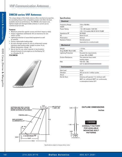
DMC50 series <strong>VHF</strong> <strong>Antennas</strong><br />
The unique design of this blade antenna offers mechanical properties<br />
far exceeding those of any competitive product and offers the best<br />
available electrical performance. The DMC50 is the lowest cost,<br />
lightest weight and strongest blade antenna in current use on<br />
commercial jet aircraft.<br />
Features<br />
• Maximum protection against corona and direct impact p-static<br />
• Unique ruggedness (withstands 10 G at resonance for one<br />
million cycles)<br />
• Lightning protection of associated equipment as well<br />
as antenna<br />
• Factory replaceable leading edge<br />
• An extra strength version for use on unimproved runway<br />
(stainless steel leading edge; weight increase 14 oz)<br />
(Model designation change –/S)<br />
• Hot air duct for use, when required, in top locations<br />
directly forward of a jet engine as on the Boeing 727<br />
or a Douglas DC-10<br />
P/N DMC50<br />
Specifications<br />
Electrical<br />
Frequency Range<br />
116 to 156 MHz<br />
VSWR < 2:1<br />
Power Rating<br />
-1 & -3/B models 1 kW CW;<br />
-2 & -11A models 500 W CW @ 75,000’<br />
Impedance RF<br />
50 OHMS<br />
DC<br />
Short Circuit<br />
Polarization<br />
Vertical<br />
Radiation Pattern<br />
Omnidirectional<br />
(equivalent to a vertical stub)<br />
Mechanical<br />
Weight<br />
Drag (35,000' Mach 0.89)<br />
Lightning Protection<br />
Erosion Resistance<br />
FAA<br />
Environmental<br />
Side Load<br />
Vibration<br />
Shock<br />
Hot Air Duct<br />
< 3.5 lbs.<br />
3 lbs.<br />
Exceeds the requirements<br />
of spec MIL-A-9094C<br />
The antennas have metal<br />
leading edges<br />
TSO-37d, -38d,<br />
CAT F2 ABCXXFXXSXXXXXXXXXX<br />
12 psi<br />
10 G at res for 1 million cycles<br />
30 G<br />
Antenna will operate 1 hr. minimum with<br />
400°F air; withstand 500°F air continuously<br />
in atmosphere below 32°F<br />
ANTENNA MAY BE 0.128 DIA<br />
DRILLED FORE OR AFT FOR<br />
SENSE ANTENNA ATTACHMENT<br />
3.62<br />
- +<br />
AIR OUTLET<br />
-1 AND -3/B<br />
0.34<br />
OUTLINE DIMENSIONS<br />
Inches<br />
FIBERGLASS<br />
REPLACEABLE<br />
ALUMINUM ALLOY<br />
38° 30'<br />
16.0<br />
1.22<br />
0.25<br />
-1 SHOWN<br />
CONSULT FACTORY<br />
FOR AVAILABLE<br />
MOUNTING BOLT<br />
PATTERNS<br />
0.85<br />
0.18 DIA DRAIN<br />
10.87<br />
16.5<br />
2.78<br />
Specifications subject to change without notice.<br />
142<br />
2 1 4 . 3 2 0 . 9 7 7 0 D a l l a s Av i o n i c s 8 0 0 . 5 2 7 . 2 5 8 1
<strong>VHF</strong> <strong>VHF</strong> <strong>Communication</strong> <strong>Antennas</strong> <strong>Antennas</strong><br />
DM C50-17 <strong>VHF</strong> Antenna<br />
The DM C50-17 series <strong>VHF</strong> <strong>Communication</strong> <strong>Antennas</strong> have incorporated<br />
design improvements to enhance corona threshold, corrosion protection,<br />
and drag characteristics.<br />
The DM C50-17 series provides the lightest weight and strongest blade<br />
antenna at lower cost for current use on commercial jet aircraft.<br />
In addition to its low initial price, further cost reductions are realized due<br />
to the weight and drag reduction of the antenna. The fuel saving per<br />
ship-set is calculated to be 160.5 gallons per aircraft per year.<br />
The DM C50-17 antenna has been selected as original equipment for<br />
the Boeing 757 and 767, and 777 aircraft. Other models in the DM C50-17<br />
series can also be used on Boeing 707, 727, 737, 747; Douglas DC-8,<br />
DC-9, and DC-10; Aerospatiale A300 series; and other commercial<br />
aircraft. Many of the DM C50-17 series are interchangeable with other<br />
types of antennas presently in use.<br />
P/N DM C50-17<br />
FWD<br />
Specifications<br />
Electrical<br />
Frequency Range<br />
116 to 156 MHz<br />
VSWR 2.0:1<br />
Power<br />
1 kW CW<br />
Impedance<br />
50 OHMS<br />
Polarization<br />
Vertical<br />
Radiation Pattern<br />
Omnidirectional<br />
(equivalent to a vertical stub)<br />
Mechanical<br />
Weight<br />
Connectors<br />
1.50 R<br />
(3.310)<br />
3.3 lbs.<br />
C Female<br />
3.62<br />
(9.195)<br />
OUTLINE DIMENSIONS<br />
Inches (Centimeters)<br />
1.00 R<br />
(2.50)<br />
0.34<br />
(90.864)<br />
<strong>Avionics</strong> & Accessories<br />
EDO Corp./Dorne & Margollin<br />
0.19 DIA (483)<br />
DRAIN HOLE<br />
THROUGH<br />
NEAR SIDE ONLY<br />
TYP 2 PL<br />
16.0<br />
(40.64)<br />
2.78<br />
(7.061)<br />
1.22<br />
(3.099)<br />
0.25<br />
(0.635)<br />
0.85<br />
(2.159)<br />
10.875<br />
(27.6225)<br />
1.00<br />
(2.540)<br />
1.560<br />
(3.9624)<br />
9.15<br />
(23.241)<br />
2.96<br />
(7.518)<br />
0.262 (0.6528) DIA<br />
10 HOLES CSK 100∞<br />
TO 0.510 (1.2954) DIA<br />
FAR SIDE CSKS<br />
1.840<br />
(4.6736)<br />
1.640<br />
(4.1656)<br />
1.85<br />
(4.699)<br />
3.000<br />
(7.6200)<br />
4.000<br />
(10.1600)<br />
6.000<br />
(15.2400)<br />
12.48<br />
(31.953)<br />
9.000<br />
(22.8600)<br />
1.280<br />
(3.2512)<br />
O-RING GROOVE<br />
Specifications subject to change without notice.<br />
2 1 4 . 3 2 0 . 9 7 7 0 D a l l a s Av i o n i c s 8 0 0 . 5 2 7 . 2 5 8 1<br />
143
<strong>VHF</strong> <strong>VHF</strong> <strong>Communication</strong> <strong>Antennas</strong> <strong>Antennas</strong><br />
<strong>Avionics</strong> & Accessories<br />
EDO Corp./Dorne & Margollin<br />
DM C57-1 Low Profile Metal Blade Radio<br />
Telephone Antenna<br />
The DM C57-1 antenna has achieved a design breakthrough that has<br />
not compromised performance. Previous designs were 6 to 7" high and<br />
heavier. The DM C57-1 is only three and a half inches high and weighs<br />
8 ounces.<br />
The DM C57-1 operates with all airborne radio telephone systems in<br />
the 450-470 MHz frequency range. Reduced maintenance costs are<br />
achieved through the use of this low profile, all metal blade as a result<br />
of its unequalled mechanical strength and built-in reliability. The DM<br />
C57-1 is currently in use and field proven on business and commercial<br />
aircraft. This low drag antenna has extremely high side load strength and<br />
its construction is completely sealed to prevent damage from moisture,<br />
Skydrol, or other contaminants.<br />
P/N DM C57-1<br />
Specifications<br />
Electrical<br />
FrequencyRange<br />
450 to 470 MHz<br />
VSWR<br />
< 2.0:1 454 to 459 MHz<br />
< 2.5:1 450 to 470 MHz<br />
Efficiency > 85%<br />
Impedance<br />
50 OHMS<br />
Power<br />
100 Watts<br />
Polarization<br />
Vertical<br />
Radiation Pattern<br />
Omnidirectional<br />
Gain<br />
Equal to quarter wave stub<br />
Mechanical<br />
Connector<br />
N (female)<br />
Weight<br />
8 oz. maximum (0.22 Kg)<br />
Finish<br />
White<br />
Max Air Speed<br />
0.85 Mach<br />
Temp Range<br />
-65°F to +250°F<br />
Altitude 70,000’<br />
Drag<br />
5.5 oz. @ 25,000’ @ 0.85 Mach<br />
OUTLINE DIMENSIONS<br />
Inches (Centimeters)<br />
0.218 DIA (0.55) CSK 100∞ x<br />
0.375 DIA (0.95) 4 PL<br />
1.062 TYP<br />
(2.70) 0.531 TYP<br />
(0.35)<br />
1.187<br />
(3.01)<br />
2.375<br />
(6.03)<br />
1.89 REF<br />
(4.8)<br />
0.18<br />
(0.46)<br />
3.50 MAX<br />
(8.89)<br />
0.25 R TYP<br />
(0.64)<br />
0.12<br />
(0.30)<br />
1.75<br />
(4.45)<br />
0.50 R TYP<br />
(1.27)<br />
4.9 MAX<br />
(12.45)<br />
2.18 REF<br />
(5.54)<br />
0.62<br />
(1.57)<br />
0.87<br />
(2.21)<br />
C<br />
Specifications subject to change without notice.<br />
144<br />
2 1 4 . 3 2 0 . 9 7 7 0 D a l l a s Av i o n i c s 8 0 0 . 5 2 7 . 2 5 8 1
<strong>VHF</strong> <strong>VHF</strong> <strong>Communication</strong> <strong>Antennas</strong> <strong>Antennas</strong><br />
Specifications<br />
Electrical<br />
Frequency Range -1 118 to 137 MHz<br />
Frequency Range -17 116 to 152 MHz<br />
VSWR<br />
2.0:1 maximum<br />
Power<br />
50 Watts<br />
Impedance<br />
50 OHMS<br />
Polarization<br />
Vertical<br />
Radiation Pattern<br />
Omnidirectional<br />
Gain<br />
Equivalent to a quarter wave stub<br />
Drag, Sea Level @ 250 MPH 0.5 lbs.<br />
Side Load Strength<br />
To 3 psi<br />
Altitude Performance 35,000’<br />
TSO<br />
C37d & C38d<br />
D0160C ENV CAT.<br />
F2-ABCXXXXXXXXXXXXXXXX<br />
DC Resistance<br />
Grounded<br />
Mechanical<br />
Weight<br />
1.6 lbs.<br />
Finish<br />
White<br />
Connectors<br />
BNC (female)<br />
DM C60 Series <strong>VHF</strong> <strong>Antennas</strong><br />
The DM C60 is a vertically polarized <strong>VHF</strong> communications antenna<br />
designed for either top or bottom fuselage mounting. The antenna<br />
covers the frequency range of 118-137 MHz (-1) or 116-152 MHz (-17)<br />
for both transmitting and receiving applications. Electrical elements<br />
of the antenna are completely sealed by foamed-in-place resin within<br />
an outer fiberglass housing. As a result, the antenna is rugged enough<br />
for use on both commercial and general aviation aircraft.<br />
P/N DM C60-<br />
FWD<br />
22<br />
OUTLINE DIMENSIONS<br />
Inches (Centimeters)<br />
7.2<br />
(18.80)<br />
0.125<br />
72<br />
11.9<br />
(30.25)<br />
0.50<br />
(1.27)<br />
<strong>Avionics</strong> & Accessories<br />
EDO Corp./Dorne & Margollin<br />
0.50 DIA<br />
8.65<br />
(21.80)<br />
1.31<br />
1.91<br />
NOTE 1<br />
0.375 0.375<br />
1.25<br />
2.50 1.75<br />
0.96<br />
3.5<br />
MAX<br />
(8.56)<br />
0.48<br />
2.78<br />
6.40<br />
0.225 DIA, 6 HOLES<br />
Notes: 1. DM C60-1 AS SHOWN<br />
DM C60-17-1 DIMENSION IS<br />
2.12 IN. MAX (5.33 cm)<br />
NOTE: A DENOTES<br />
LOCATION OF HOLE<br />
0.625 DIA<br />
2.781<br />
6.406<br />
A<br />
1.750<br />
A<br />
A<br />
1.375<br />
0.875 2.500<br />
0.687<br />
A<br />
1.250<br />
A<br />
A<br />
1.91 (-1)<br />
2.12 (-17)<br />
6 "A" HOLES<br />
FOR NO. 10 SCREWS<br />
Specifications subject to change without notice.<br />
2 1 4 . 3 2 0 . 9 7 7 0 D a l l a s Av i o n i c s 8 0 0 . 5 2 7 . 2 5 8 1<br />
145
<strong>VHF</strong> <strong>VHF</strong> <strong>Communication</strong> <strong>Antennas</strong> <strong>Antennas</strong><br />
<strong>Avionics</strong> & Accessories<br />
DM C63 Series <strong>VHF</strong> Antenna<br />
The DM C63 series antennas are <strong>VHF</strong> communication antennas designed<br />
for high mechanical strength with machine tapered aluminum alloy<br />
radiating elements. These vertically polarized antennas cover the<br />
frequency range of 118-137 or 138-174 MHz for both transmitting and<br />
receiving applications.<br />
The DM C63-1/A and DM C63-4/A are designed for mounting on top of<br />
the fuselage. The DM C63-2 and DM C63-3/A are low profile "bentback"<br />
radiating element designs for mounting on the bottom of the fuselage.<br />
They are well suited for helicopter installations.<br />
All DM C63 series antennas are supplied with a gasket and a<br />
doubler plate.<br />
P/N DM C63-<br />
EDO Corp./Dorne & Margollin<br />
OUTLINE DIMENSIONS<br />
Inches (Centimeters)<br />
2.19<br />
(5.56)<br />
0.562 DIA<br />
(1.43)<br />
1.375<br />
(3.49)<br />
3.25<br />
(8.26)<br />
0.687<br />
(1.74)<br />
0.218 DIA (0.55)<br />
CSK 100° x<br />
0.440 DIA (1.118)<br />
FAR SIDE<br />
3 PLACES<br />
1.375<br />
(3.49)<br />
Notes:<br />
1. 0.032 thick core gasket supplied with antenna<br />
2. Doubler plate supplied with antenna<br />
Specifications<br />
Electrical<br />
Frequency Range<br />
VSWR<br />
Power<br />
Impedance<br />
Polarization<br />
Radiation Pattern<br />
Gain<br />
TSO<br />
Mechanical<br />
Weight<br />
Finish<br />
Connectors<br />
Environmental<br />
Per D0160c<br />
118 to 137 MHz; DM C63-1/A, DM C63-2/A<br />
138 to 174 MHz; DM C63-3/A, DM C63-4/A<br />
2.0:1 DM C63-1/A<br />
3.0:1 DM C63-2<br />
3.5:1 DM C63-3/A<br />
3.0:1 DM C63-4/A<br />
50 Watts<br />
50 OHMS<br />
Vertical<br />
Omnidirectional<br />
Equivalent l/4 stub<br />
C37d & C38d<br />
8 oz.<br />
White<br />
BNC (female)<br />
F2-ABCXXXXXXXXXXXXXXXX<br />
20.8 MAX<br />
(52.83)<br />
8.0 MAX<br />
(20.32)<br />
DM C63–3/A<br />
AIRCRAFT<br />
SKIN (REF)<br />
60°<br />
4.63<br />
(11.76)<br />
DM C63–4/A<br />
DM C63–1/A<br />
16.42 REF<br />
(41.71)<br />
17.0<br />
(43.18)<br />
20.50 MAX<br />
(52.07)<br />
8.1 MAX<br />
(20.57)<br />
DM C63–2<br />
Specifications subject to change without notice.<br />
AIRCRAFT<br />
60°<br />
SKIN (REF)<br />
AIRCRAFT<br />
SKIN (REF)<br />
60°<br />
AIRCRAFT<br />
SKIN (REF)<br />
60°<br />
4.63<br />
(11.76)<br />
4.63<br />
(11.76)<br />
4.63<br />
(11.76)<br />
146<br />
2 1 4 . 3 2 0 . 9 7 7 0 D a l l a s Av i o n i c s 8 0 0 . 5 2 7 . 2 5 8 1
<strong>VHF</strong> <strong>VHF</strong> <strong>Communication</strong> <strong>Antennas</strong> <strong>Antennas</strong><br />
DM C70 Series <strong>VHF</strong> 360/720 Channel<br />
Broadband <strong>Antennas</strong><br />
The DM C70 series <strong>VHF</strong> <strong>Communication</strong> <strong>Antennas</strong> are designed for top<br />
or bottom installation on high-performance, single, twin and turbo engine<br />
fixed and rotary wing aircraft. These uniquely designed antennas offer<br />
mechanical strength and high-electrical efficiency to provide maximum<br />
reliability and full 360/720 channel transceiver operation. The lightweight<br />
profile is unobtrusive, resists icing and offers low drag.<br />
The DM C70-3 is directly interchangeable with the following part<br />
numbers: C598501-0104, VF 10-210, CI 109, and CI 121.<br />
The DM C70-4 which supersedes the DM C70-2, is specifically designed<br />
for bottom installations, where ground clearance does not permit the use<br />
of other DM C70 series antennas. The DM C70-4 provides a higher degree<br />
of efficiency to assure maximum performance from your transceiver.<br />
The DM C70-6, and DM C70-9 variants of the DM C70-1/A, have a<br />
different mounting hole pattern and connector location. All other<br />
characteristics remain the same.<br />
P/N DM C70-<br />
Specifications<br />
Electrical<br />
Frequency Range<br />
118 to 137 MHz<br />
VSWR 2.0:1 DM C70, -1/A, -3, -6, -9<br />
2.5:1 DM C70-4<br />
Polarization<br />
Vertical<br />
Power<br />
50 Watts<br />
Impedance<br />
50 OHMS<br />
Radiation Patterns<br />
Omnidirectional<br />
Connectors<br />
BNC (female)<br />
Mechanical<br />
Weight<br />
Finish<br />
TSO<br />
D0160c ENV CAT<br />
Speed Rating<br />
FWD<br />
DM C70–1/A<br />
DM C70–3<br />
DM C70–4<br />
12 oz. (0.34 Kg)<br />
White polyurethane<br />
C37d, C38d<br />
F2-ABCXWFDXSXXXXXXXXXX<br />
DM C70-1/A, -4, -6, -9, 400 MPH<br />
DM C70-3, 250 MPH<br />
Specifications subject to change without notice.<br />
MOUNTING HOLE PATTERN<br />
Inches (Centimeters)<br />
0.170 (0.432)<br />
4 MTG HOLES CSK 100∞ ON<br />
FARSIDE<br />
<strong>Avionics</strong> & Accessories<br />
EDO Corp./Dorne & Margollin<br />
0.81<br />
(2.057)<br />
2.58<br />
(6.55)<br />
1.62<br />
(4.114)<br />
OUTLINE DIMENSIONS<br />
Inches (Centimeters)<br />
FWD<br />
DM C70–1/A<br />
DM C70–6<br />
DM C70–9<br />
15.00<br />
(38.10)<br />
MAX<br />
60<br />
15.00<br />
(38.10)<br />
MAX<br />
60<br />
DM C70–3<br />
Notes: 1. 0.080 MIN Thk gasket supplied with antenna.<br />
0.130 MAX<br />
2. Doubler plate supplied with antenna.<br />
60<br />
DM C70–4<br />
20.50<br />
(52.07)<br />
MAX<br />
8.90<br />
60 (22.61)<br />
MAX<br />
FWD<br />
1.125<br />
(2.86)<br />
1.750<br />
(4.45)<br />
0.875<br />
(2.22)<br />
DM C70–6<br />
DM C70–9<br />
0.875<br />
(2.222)<br />
1.750<br />
(4.45)<br />
1.00<br />
(2.540)<br />
1.750<br />
(4.445)<br />
2.50<br />
(6.35)<br />
0.750<br />
(1.91)<br />
MOUNT USING FOUR NO. 10<br />
STAINLESS STEEL SCREWS<br />
5.37<br />
(13.65)<br />
4.26<br />
(10.820)<br />
1.50<br />
(3.81)<br />
3.62<br />
0.75<br />
(1.91)<br />
0.203 DIA (0.516)<br />
CSK 100∞ x 390 (0.990)<br />
DIA<br />
(FARSIDE)<br />
2 1 4 . 3 2 0 . 9 7 7 0 D a l l a s Av i o n i c s 8 0 0 . 5 2 7 . 2 5 8 1<br />
147
Couplers Couplers && Diplexers Diplexers<br />
<strong>Avionics</strong> & Accessories<br />
EDO Corp./Dorne & Margollin<br />
DM H21 through DM H24<br />
Antenna Couplers<br />
These Antenna Couplers are specifically designed to couple multiple<br />
receiver systems to a single antenna with a minimum of insertion loss.<br />
The couplers are designed to electronically split the received signals<br />
equally between the systems. In this manner, a single antenna may<br />
feed redundant systems or serve a dual-function role (e.g., Glide Slope<br />
and VOR/LOC).<br />
The ruggedly built couplers are housed in aluminum cases with all<br />
circuit elements fully encapsulated. General specifications applicable<br />
to all couplers are provided in this sheet, while Table 1 indicates the<br />
recommended function of the particular type.<br />
P/N DM H21-<br />
P/N DM H22-<br />
P/N DM H23-<br />
P/N DM H24-<br />
Specifications<br />
Electrical<br />
Frequency Range<br />
108 to 118 MHz<br />
329 to 335.3 MHz<br />
VSWR < 1.5:1<br />
Impedance<br />
50 OHMS<br />
Isolation<br />
VOR/LOC—VOR/LOC<br />
> 20 dB<br />
VOR/LOC from glide slope<br />
> 40 dB<br />
Glide slope from VOR/LOC<br />
> 14 dB<br />
Insertion Loss Glide slope port DM H22-1<br />
0.5 dB max & DM H23-1<br />
VOR/LOC port, DM H22-1 0.5 dB max<br />
VOR/LOC ports, DM H21-1,<br />
3.5 dB maximum including power split<br />
DM H23-1 & glide slope<br />
Ports DM H24-1<br />
TSO<br />
C34c, C35d, C36d, C40c<br />
Mechanical<br />
Weight<br />
4 oz. maximum<br />
0.75<br />
0.37<br />
DM H21-1<br />
DM H22 -1<br />
DM H24-1<br />
3 CONN BNC<br />
OUTLINE DIMENSIONS<br />
Inches<br />
* DM H23-1 4 CONN, 2 EACH END BNC<br />
DM H23-2 4 CONN, 3 EACH END BNC AND 1 TNC<br />
1.03<br />
0.203 DIA (2 HOLES)<br />
*<br />
*<br />
0.44<br />
0.47<br />
TYP<br />
0.87<br />
1.75<br />
0.250<br />
2.375<br />
0.500<br />
1.87<br />
0.687<br />
0.250<br />
TABLE 1<br />
Coupler Frequency (MHz) VSWR Weight Description<br />
DM H21-1 108-118 1.5:1 0.25 lbs Dual VOR or dual marker beacon will permit operation of two NAV<br />
receivers from one VOR antenna or two marker beacon receivers<br />
from one marker beacon antenna.<br />
DM H22-1 108-118 1.5:1 0.25 lbs Single VOR and single GS will permit operation of one NAV and<br />
329-335.3 one glide slope receiver from one VOR antenna.<br />
DM H23-1 108-118 1.5:1 0.25 lbs Dual VOR and single GS permits operation of two NAV and one<br />
329-335.3 glide slope receiver from one VOR/LOC antenna.<br />
DM H24-1 329-335.3 1.5:1 0.25 lbs Dual glide slope permits operation of two glide slope receivers<br />
from one glide slope antenna.<br />
Specifications subject to change without notice.<br />
148<br />
2 1 4 . 3 2 0 . 9 7 7 0 D a l l a s Av i o n i c s 8 0 0 . 5 2 7 . 2 5 8 1
Couplers Couplers && Diplexers Diplexers<br />
DM H69-1 Quadraplexer<br />
Antenna Coupler<br />
The DM H69-1 provides in one small lightweight component the ability<br />
to operate dual NAVS and dual Glide Slope receivers from one VOR<br />
antenna. As with our coupler series, the DM H69-1 is designed to couple<br />
multiple systems to the single antenna with minimum insertion loss but<br />
with more than adequate isolation to prevent intersystem cross-talk.<br />
The ruggedly built DM H69-1 is housed in an aluminum case and all<br />
circuit components are fully encapsulated for vibration protection as<br />
well as waterproof protection.<br />
P/N DM H69-1<br />
Specifications<br />
Electrical<br />
Frequency Range<br />
VSWR<br />
Impedance<br />
Insertion Loss<br />
Isolation<br />
GS-GS<br />
Connectors<br />
108 to 118 MHz; 329 to 335.3 MHz<br />
2.0:1 maximum<br />
50 OHMS<br />
VOR 1 dB maximum; GS 1 dB maximum<br />
VOR 18 dB minimum<br />
VOR-GS 20 dB minimum<br />
18db minimum<br />
BNC (male)<br />
<strong>Avionics</strong> & Accessories<br />
2.81<br />
(71.37)<br />
2.375<br />
(60.325)<br />
0.65<br />
(16.51)<br />
GLIDE<br />
SLOPE REC<br />
NAV<br />
COM RCVR<br />
0.50<br />
(12.70)<br />
0.87<br />
(22.10)<br />
0.44<br />
(11.18)<br />
0.75<br />
(19.05)<br />
1.75<br />
(44.45)<br />
GLIDE<br />
SLOPE REC<br />
ANT.<br />
NAV<br />
COM RCVR<br />
CONNECTORS:<br />
BNC MALE 5 PLACES<br />
0.93<br />
(23.62)<br />
0.47 TYP.<br />
(11.94)<br />
1.87<br />
(47.50)<br />
Mechanical<br />
Weight<br />
Environmental<br />
Environmental Category<br />
5 oz.<br />
MIL-E-5400<br />
Class II<br />
Vibration Curve 1A<br />
EDO Corp./Dorne & Margollin<br />
1.03<br />
(26.16)<br />
0.59 TYP<br />
(14.99)<br />
2 1 4 . 3 2 0 . 9 7 7 0 D a l l a s Av i o n i c s 8 0 0 . 5 2 7 . 2 5 8 1<br />
149
Navigation Navigation <strong>Antennas</strong> <strong>Antennas</strong><br />
<strong>Avionics</strong> & Accessories<br />
EDO Corp./Dorne & Margollin<br />
DM N4-4 Antenna System<br />
The DM N4-4 Antenna System has been designed to minimize bearing<br />
errors in the reception of VOR and ILS signals. It provides considerably<br />
more gain at the horizon (particularly during banks) than do fuselage<br />
mounted "deerhorn" or "vee" antennas. It has substantially greater<br />
discrimination against vertically polarized signals; and when properly<br />
installed on helicopters, it provides much greater rejection of rotor<br />
modulation than can be obtained with these other antennas. As a<br />
result, it provides better signal to noise ratios and smaller errors than is<br />
otherwise available.<br />
The DM N4-4 Antenna consists of two (approximately semicircular)<br />
center-fed half-loops and a cable harness. Because the DM N4-4 has<br />
been designed specifically for light planes and helicopters, lightweight<br />
rugged construction has been stressed. It is built of round magnesium<br />
tubing and weighs only 2 pounds.<br />
P/N DM N4-4<br />
Specifications<br />
Electrical<br />
Frequency Range<br />
108 to 122 MHz<br />
VSWR < 5.0 to 1<br />
Gain<br />
0 ± 2 dB<br />
Impedance<br />
50 OHMS<br />
Polarization<br />
Horizontal<br />
Efficiency 95%<br />
Radiation Pattern<br />
Omnidirectional in the azimuth plane.<br />
Approx cos. Ø in the vertical plane.<br />
Mechanical<br />
Weight (without cable)<br />
Connectors<br />
Military<br />
FAA<br />
2 lbs.<br />
BNC<br />
MIL-E-5400<br />
MIL-T-5422<br />
TSO-C40a<br />
0.213 DIA (5.41)<br />
CSK 100∞ x 0.395 DIA (10.03)<br />
6 PLACES EQUALLY SPACED<br />
ON A 2.312 BC (58.72)<br />
3.00 DIA<br />
17.00<br />
OUTLINE DIMENSIONS<br />
Inches<br />
L1<br />
8.50<br />
Note:<br />
EACH HALF LOOP MUST<br />
BE INSTALLED AS SHOWN, ONE<br />
WITH CONNECTOR FORWARD,<br />
OTHER WITH CONNECTOR AFT<br />
MOUNTING SURFACES<br />
UP TO 36" APART WITH<br />
STANDARD CABLE<br />
HARNESS. SPECIAL<br />
CABLE REQUIRED FOR<br />
GREATER SEPARATION<br />
L2<br />
Specifications subject to change without notice.<br />
150<br />
2 1 4 . 3 2 0 . 9 7 7 0 D a l l a s Av i o n i c s 8 0 0 . 5 2 7 . 2 5 8 1
Navigation Navigation <strong>Antennas</strong> <strong>Antennas</strong><br />
DM N4-7 & DM N4-8 VOR/LOC<br />
Balanced Loop <strong>Antennas</strong><br />
Increased VOR/LOC range and minimized bearing errors can be achieved<br />
with any airborne VOR receiver through the use of these DM N4-7 and<br />
DM N4-8.<br />
Each DM N4 system utilizes two center-fed, half-loops and a cable<br />
harness, enabling "closed loop" current flow. This provides better<br />
signal-to-noise ratios and higher rejection of cross-polarized signals.<br />
In terms of system performance, this means that smaller signals can be<br />
received and bearing errors, particularly those induced by banking, are<br />
greatly reduced.<br />
These rugged antennas have been selected and service proven on such<br />
aircraft as the Lockheed Jet-star, P-3A, and C-141 Starlifter, Bell UH1B<br />
helicopter, Sikorsky H34 helicopter, Convair 340, Aero Commander, North<br />
American Sabreliner, Douglas DC-3, Beech King Air and many other<br />
corporate and commercial aircraft.<br />
P/N DM N4-7<br />
P/N DM N4-8<br />
Specifications<br />
Electrical<br />
Frequency Range<br />
108 to 122 MHz<br />
VSWR
Navigation Navigation <strong>Antennas</strong> <strong>Antennas</strong><br />
<strong>Avionics</strong> & Accessories<br />
EDO Corp./Dorne & Margollin<br />
DM N4-15 & DM N4-33 Low Drag,<br />
VOR/LOC Balanced Loop, <strong>Antennas</strong><br />
The DM N4-15 and DM N4-33 <strong>Antennas</strong> are designed for use on highperformance<br />
aircraft where aerodynamic drag and component weight<br />
must be held at a minimum. These systems provide increased range and<br />
reduced bearing error, versus dipole type installations. Rugged metal<br />
edges provide erosion resistance; flush glass fiber housings ensure<br />
smooth airflow and reduced drag; and each assembly is foam-filled for<br />
maximum reliability.<br />
The DM N4-15 is intended, primarily, for new aircraft installations,<br />
but can be installed, as a retrofit, when dual-antenna capability<br />
is required.<br />
The DM N4-33 is intended for retrofit, or antenna modifications, on<br />
existing aircraft and is designed for ease of installation. Dual-antenna<br />
capability can be obtained by using a DM Hybrid Coupler (H21 series).<br />
P/N DM N4-15<br />
P/N DM N4-33<br />
Specifications<br />
Electrical<br />
Frequency Range 108 to 118 MHz<br />
VSWR<br />
5:1 maximum<br />
Polarization<br />
Horizontal<br />
Impedance<br />
50 OHMS<br />
Connectors<br />
TNC<br />
Radiation Pattern Omnidirectional in the azimuth plane,<br />
approx. cos Ø in the vertical plane<br />
Mechanical<br />
Weight 5.5 lbs. DM N4-15<br />
5.2 lbs. DM N4-33<br />
Construction<br />
Erosion resistant metal edged<br />
fiberglass housing, foam filled with<br />
leading & trailing edge<br />
erosion protection<br />
FAA<br />
TSO-C40a<br />
2.50<br />
0.15 MAX<br />
1.37<br />
FWD (OPTIONAL)<br />
21<br />
4.87 R<br />
6.50<br />
1.0 TNC<br />
CONN<br />
TNC<br />
CONN<br />
30" SEPARATION<br />
COMPATIBLE WITH<br />
STANDARD CABLE<br />
HARNESS<br />
OUTLINE DIMENSIONS<br />
DM N4-15 DUAL CONNECTOR<br />
Inches (Centimeters)<br />
FWD (OPTIONAL)<br />
TWO<br />
CONNECTORS<br />
ON DM N4-15;<br />
ONE<br />
CONNECTOR<br />
ON DM N4-33<br />
1.936<br />
4.50<br />
0.78<br />
9.00<br />
3.00<br />
4.62 5.00<br />
10.00<br />
1.50<br />
0.218 DIA, 8 HOLES<br />
100˚ CSK<br />
OPPOSITE SIDE<br />
TO 0.385 DIA<br />
GROUNDING<br />
STUDS ON<br />
DM N4-15 ONLY<br />
6.53<br />
30"<br />
21<br />
TNC<br />
CONN<br />
4.87 R<br />
9.500 9.500<br />
MOUNTING BASE<br />
DM N4-33 SINGLE CONNECTOR<br />
Specifications subject to change without notice.<br />
152<br />
2 1 4 . 3 2 0 . 9 7 7 0 D a l l a s Av i o n i c s 8 0 0 . 5 2 7 . 2 5 8 1
Navigation Navigation <strong>Antennas</strong> <strong>Antennas</strong><br />
DM N4-17 series VOR/LOC/<br />
Glide Slope <strong>Antennas</strong><br />
The DM N4-17 VOR/LOC/Glide slope antenna is designed for general<br />
aviation, commercial, and military aircraft that operate up to Mach 1.0.<br />
The DM N4-17 is designed and qualified to provide a low-cost,<br />
lightweight, low-drag antenna for state-of-the-art avionics systems.<br />
The antenna is not only TSO'd, its performance parameters exceed<br />
the environmental specifications of MIL-E-5400 Class 3 equipment.<br />
Therefore, the DM N4-17 can be installed on single engine to jet<br />
engine aircraft.<br />
The balanced loop design of the DM N4-17 assures an omnidirectional<br />
radiation pattern at the horizon to obtain the maximum signal for<br />
standard VOR and area navigation, which in turn provides more<br />
receiving distance and reliable system performance.<br />
The standard system is the DM N4-17/N, which consists of two antenna<br />
elements (DM N4-17-1/N), two feed cables and gaskets (DM U212-1<br />
and DM U235-1 respectively), and a phasing coupler (DM N4-17-2).<br />
Dual output couplers (DM N4-17-4) are available as well.<br />
P/N DM N4-17/N—VOR/LOC/GS Single output<br />
P/N DM N4-17/P—VOR/LOC Dual output<br />
P/N DM N4-17/S—VOR/LOC/GS Single output<br />
12.18 (308.9)<br />
14.00 (355.6)<br />
0.21<br />
(5.3<br />
12.18<br />
(308.9)<br />
Specifications<br />
Electrical<br />
Frequency<br />
108 to 118 MHz VOR/LOC<br />
329 to 335.3 MHz Glide slope<br />
VSWR<br />
5.0:1 maximum<br />
Polarization<br />
Horizontal<br />
Gain<br />
0 ± 2 dB<br />
Impedance<br />
50 OHMS<br />
Radiation Pattern<br />
Omnidirectional VOR/LOC<br />
Forward pointing glide slope<br />
Lightning Protection DC short<br />
Mechanical<br />
Weight<br />
1.32 lbs.<br />
Connector<br />
BNC (female*)<br />
Cable Length 27”*<br />
Side Load<br />
17 psi<br />
FAA Approval<br />
C34e, C36e, C40c<br />
D0138 ENV. CAT.<br />
AA5XXXXXHDXS<br />
<strong>Avionics</strong> & Accessories<br />
EDO Corp./Dorne & Margollin<br />
RCVR<br />
* Consult <strong>Dallas</strong> <strong>Avionics</strong> for other connector<br />
types and cable lengths.<br />
Specifications subject to change without notice.<br />
OUTLINE DIMENSIONS<br />
Inches (Centimeters)<br />
LEADING<br />
EDGE<br />
1.125<br />
A<br />
A<br />
+<br />
+<br />
3.187<br />
+<br />
A<br />
A<br />
+<br />
+<br />
0.500 DIA<br />
0.632<br />
1.265<br />
5.480<br />
4-A HOLES<br />
FOR NO. 8 SCREWS<br />
(0.166 DIA)<br />
2 1 4 . 3 2 0 . 9 7 7 0 D a l l a s Av i o n i c s 8 0 0 . 5 2 7 . 2 5 8 1<br />
153
Navigation Navigation <strong>Antennas</strong> <strong>Antennas</strong><br />
<strong>Avionics</strong> & Accessories<br />
DM N4-45 VOR/LOC Antenna<br />
The DM N4-45 continues the DM N4-15 tradition to provide superior<br />
VOR/ILS systems performance for high-performance aircraft where<br />
aerodynamic drag and weight must be held to a minimum.<br />
The DM N4-45 has been designed from the ground up to incorporate<br />
latest developments in structural materials, but retaining the electrical<br />
performance so many have come to expect from a balanced loop<br />
VOR/LOC antenna.<br />
The complete DM N4-45 fit and function have not changed the form<br />
from that of the DM N4-15. While identical in all outward appearances,<br />
it incorporates a new integrated radiating boot material design for<br />
today's environment.<br />
P/N DM N4-45<br />
Specifications<br />
Electrical<br />
Frequency Range<br />
108 to 118 MHz<br />
VSWR 5.0:1<br />
Polarization<br />
Horizontal<br />
Impedance<br />
50 OHMS<br />
Connectors<br />
TNC (female)<br />
Radiation Pattern<br />
Omnidirectional<br />
Mechanical<br />
Weight<br />
5.5 lbs. (2.46 Kg)<br />
EDO Corp./Dorne & Margollin<br />
OUTLINE DIMENSIONS<br />
Inches (Centimeters)<br />
2.5<br />
(6.35)<br />
0.218 (0.5537) DIA CSK<br />
0.390 (0.9906) DIA<br />
100? FAR SIDE (8 PL) REF<br />
NO. 10-32<br />
STUD (REF)<br />
TYP<br />
1.25<br />
(3.175)<br />
TNC<br />
FEMALE<br />
2 PLACES<br />
9.000<br />
(22.860)<br />
6.000<br />
(15.240)<br />
3.000<br />
(7.620)<br />
0.78<br />
(1.981) TYP<br />
5.00<br />
(12.70)<br />
4.62<br />
(11.735) TYP<br />
10.0<br />
(25.40)<br />
19.0<br />
(48.26)<br />
9.50<br />
(24.130) TYP<br />
0.968<br />
(2.4587)<br />
1.936<br />
(4.9174)<br />
20.8<br />
(52.83)<br />
TNC MALE (6 PL)<br />
TYP FOR CABLES<br />
Specifications subject to change without notice.<br />
30" TYP<br />
0.97<br />
(2.463) REF<br />
0.12<br />
(0.305)<br />
10-32<br />
UNF THDD<br />
STUD (2 PL)<br />
6.7<br />
(17.018)<br />
154<br />
2 1 4 . 3 2 0 . 9 7 7 0 D a l l a s Av i o n i c s 8 0 0 . 5 2 7 . 2 5 8 1
Navigation Navigation <strong>Antennas</strong> <strong>Antennas</strong><br />
DM N9 Series Localizer/<br />
VOR/Glide Slope <strong>Antennas</strong><br />
The DM N9 series antenna provides a dual band design for both<br />
Localizer/VOR and Glide Slope systems for installation within nose<br />
radomes on high performance aircraft.<br />
The design incorporates common radiating elements into a single<br />
monolithic structure for mounting either on a bulkhead within a radome<br />
or to the radome directly. The antenna is designed with the radiating<br />
elements attached to a single curved dielectric window to provide<br />
support. In some cases, reinforcing ribs provide structural rigidity and<br />
mounting adaptability to the bulkhead for mechanical attachment and<br />
electrical grounding to the airframe.<br />
The DM N9 series is a balanced bent-back dipole antenna which renders<br />
it immune from the nose radar motion. In addition to excellent Localizer<br />
and Glide Slope patterns, many users utilize the Localizer output for<br />
forward-looking VOR as well.<br />
P/N DM N9<br />
Specifications<br />
Electrical<br />
Frequency Range<br />
108 to 118 MHz Localizer/VOR<br />
328.6 to 335.4 MHz Glide Slope<br />
VSWR < 5.0:1<br />
(immune to de-tuning from radar motion)<br />
Radiation Pattern<br />
Single broad lobe forward of aircraft<br />
Polarization<br />
Horizontal<br />
Mechanical<br />
Mounting<br />
Weight<br />
Connectors<br />
Military<br />
On inner surface of nose radome or bulkhead within radome<br />
< 2.0 lbs. (0.9 Kg)<br />
Consult factory<br />
MIL-E-5400<br />
Installation Considerations<br />
Installation is an important factor for<br />
maximum antenna performance.<br />
Each antenna design within the series<br />
must be customized for the airframe<br />
and radome interface with respect<br />
to bulkhead mounting and radius,<br />
and radome curvature. Physical size<br />
and<br />
space limitations may require an<br />
engineering analysis of your airframe<br />
and radome design. Our extensive<br />
experience with nose radome<br />
installations will enable specific<br />
OUTLINE DIMENSIONS<br />
Inches (Centimeters)<br />
<strong>Avionics</strong> & Accessories<br />
EDO Corp./Dorne & Margollin<br />
FORWARD<br />
0.242 DIA<br />
(0.615)<br />
4 PL<br />
(TYPICAL)<br />
A<br />
DOUBLE CURVATURE<br />
COUTOURED TO<br />
NOSE RADOME<br />
FIBERGLASS<br />
LAMINATE<br />
ELEMENT<br />
10.00 MAX<br />
(25.40)<br />
GLIDE SLOPE<br />
A<br />
25.00 MAX<br />
(63.50)<br />
VOR/LOC<br />
"A-A"<br />
ATTACHES HERE<br />
TO BULKHEAD<br />
Specifications subject to change without notice.<br />
2 1 4 . 3 2 0 . 9 7 7 0 D a l l a s Av i o n i c s 8 0 0 . 5 2 7 . 2 5 8 1<br />
155
Navigation Navigation <strong>Antennas</strong> <strong>Antennas</strong><br />
<strong>Avionics</strong> & Accessories<br />
EDO Corp./Dorne & Margollin<br />
DM N23-1/C VOR Antenna<br />
The DM N23-1/C, designed for the Boeing 737 aircraft, provides a<br />
concept that can be incorporated in many aircraft designs to provide<br />
integral <strong>VHF</strong> navigation systems performance.<br />
The electrical design provides two receiver operation with performance<br />
assured for CAT. III conditions. The omnidirectional radiation patterns in<br />
the horizontal plane also assure signal levels are more than required for<br />
R-NAV systems use.<br />
The DM N23-1/C Balanced Loop Array is designed for installation on<br />
the tip of the Boeing 737's vertical stabilizer. Unlike most vertical<br />
stabilizer VOR antennas, the DM N23-1/C is not freestanding. Rather<br />
the DM N23-1/C antenna system forms a structural component and<br />
exterior skin of the stabilizer.<br />
Lightning diverters and static discharges are integrated into the antenna<br />
system. In addition, both the leading and trailing edges are designed to<br />
be replaceable, thereby extending the service life of the antenna system.<br />
P/N DM N23-1C<br />
Specifications<br />
Mechanical<br />
Frequency Range<br />
108 to 118 MHz<br />
VSWR 2.3:1<br />
Impedance<br />
50 OHMS<br />
Polarization<br />
Horizontal<br />
Radiation Pattern<br />
Omnidirectional<br />
Isolation<br />
7.5 dB<br />
Electrical<br />
Weight Connectors (2) C (female)<br />
Part Numbers<br />
Antenna system DM N23-1/C<br />
Antenna element DM N23-1/C-3<br />
Tip, leading edge DM N23-1/A-1<br />
Tip, trailing edge DM N23-1/A-5<br />
Boeing Part Number 10-61333-3<br />
IAW BAC 65-73789<br />
OUTLINE DIMENSIONS<br />
MOUNTING HOLES<br />
FORWAR<br />
Forward<br />
Specifications subject to change without notice.<br />
156<br />
2 1 4 . 3 2 0 . 9 7 7 0 D a l l a s Av i o n i c s 8 0 0 . 5 2 7 . 2 5 8 1
Navigation Navigation <strong>Antennas</strong> <strong>Antennas</strong><br />
DM N42-1 VOR/LOC Loop Antenna<br />
The DM N42-1 is a tail-mounted antenna for use with VOR, localizer<br />
and glide slope receivers. It has been specially designed to provide the<br />
outstanding electrical performance of a balanced, center-fed loop at<br />
minimum cost. The input balun transformer is permanently sealed inside<br />
the center housing. Output cables extend from this transformer, through<br />
each side bar, to the feed points at the bulge on each element. This<br />
unusual configuration permits reliable, economical installation on aircraft<br />
that cruise at speeds up to 230 mph. When properly installed, the antenna<br />
receives the horizontally polarized VOR and localizer signals with uniform<br />
high sensitivity from all directions around the aircraft over the full VOR/<br />
localizer band. Because of the inherent characteristics of all balanced<br />
loop-type antennas, vertically polarized, error-producing signals are<br />
rejected. The antenna also has excellent forward reception over the<br />
glide slope band (329 to 335 MHz) and can be used for this function by<br />
adding a DMH22-1 coupler to the system.<br />
P/N DMN42-1<br />
Items supplied:<br />
• DM N42-1 antenna<br />
• Leading edge mounting bracket<br />
• Grommet<br />
• BNC connector UG 89C/U.<br />
OUTLINE DIMENSIONS<br />
Inches (Centimeters)<br />
0.75 TYP<br />
DIELECTRIC<br />
Specifications<br />
Electrical<br />
Frequency Range<br />
108 to 118 MHz<br />
329 to 335.3<br />
VSWR < 5:1<br />
Polarization<br />
Horizontal<br />
Impedance<br />
50 OHMS<br />
Radiation Pattern<br />
Omnidirectional VOR/LOC<br />
Forward pointing glide slope<br />
Mechanical<br />
DC Resistance<br />
Open circuited<br />
Weight<br />
1.0 lbs<br />
Connector<br />
BNC (female)<br />
Finish<br />
White<br />
Mounting Place Adjustment 0° to 30°<br />
TSO<br />
C40a, C34b, C36c<br />
DO138 ENV. CAT.<br />
JAJ XXXX<br />
Drag, Sea Level @ 250 mph 0.5 lbs.<br />
<strong>Avionics</strong> & Accessories<br />
EDO Corp./Dorne & Margollin<br />
16.5<br />
(41.91) CM<br />
ALUMINUM<br />
ALLOY<br />
3.05<br />
(7.77) CM<br />
3.00 (7.63)<br />
ADJUSTABLE<br />
± 1.00 (2.54) CM<br />
3.5<br />
(9.89)<br />
16.00<br />
(40.64)<br />
ADJUSTABLE 0 TO 30˚<br />
CABLE RG 58A/U<br />
Specifications subject to change without notice.<br />
2 1 4 . 3 2 0 . 9 7 7 0 D a l l a s Av i o n i c s 8 0 0 . 5 2 7 . 2 5 8 1<br />
157
Navigation Navigation <strong>Antennas</strong> <strong>Antennas</strong><br />
<strong>Avionics</strong> & Accessories<br />
EDO Corp./Dorne & Margollin<br />
DM N48 Series VOR/LOC<br />
Balanced Loop <strong>Antennas</strong><br />
The DM N48 series balanced loop design assures an omnidirectional<br />
radiation pattern at the horizon to obtain the maximum signal for standard<br />
VOR and area navigation systems installed in lightweight aircraft, medium<br />
twins, and helicopters operating up to 250 mph.<br />
The DM N48-3 antenna utilizes a phasing coupler which enables ease of<br />
installation if an access panel is not available or if the vertical stabilizer<br />
is so narrow at the point of installation it makes it necessary to install the<br />
antenna with both cable leads forward or aft.<br />
Dual VOR receiver operation is obtained when the antennas are used<br />
with the DM H21-1 diplexer.<br />
P/N DM N48<br />
Specifications<br />
Electrical<br />
Frequency Range<br />
108 to 118 MHz<br />
VSWR 5.0:1<br />
Impedance<br />
50 OHMS<br />
Polarization<br />
Horizontal<br />
Radiation Pattern<br />
Omnidirectional<br />
Mechanical<br />
Weight<br />
Connector<br />
Finish<br />
DC Resistance<br />
DM N48–1<br />
MANDATORY INSTALLATION<br />
ORIENTATION-DM N48-1<br />
(Cable leads must be at 180˚ to each<br />
other as shown)<br />
1.12 lbs (0.51 Kg)<br />
BNC (male)<br />
White polyurethane<br />
Open circuit<br />
OUTLINE DIMENSIONS AND<br />
MOUNTING HOLE PATTERN<br />
Inches (Centimeters)<br />
Notes:<br />
1. Antenna lead cables are precut.<br />
DO NOT ALTER CABLE LENGTH<br />
2. For new installations it is recommended to use double<br />
shielded coax (particularly important in helicopters.)<br />
DM N48–1–1<br />
Antenna Element<br />
DM N48–3<br />
6.25<br />
(15.88)<br />
2.5 DIA<br />
(6.35) TYP<br />
16.5 REF<br />
(41.19)<br />
14.05<br />
(35.69)<br />
MANDATORY INSTALLATION<br />
ORIENTATION-DM N48-3<br />
(Cable leads must be connected to phasing<br />
coupler as shown)<br />
CABLE (50.0 LG<br />
(127)<br />
0.171 DIA 0.434)<br />
4 HOLES EQUALLY SPACED<br />
AT 45˚ ON A 2.00 DIA (5.08) B.C.<br />
(TYP 2 PLACES)<br />
Specifications subject to change without notice.<br />
158<br />
2 1 4 . 3 2 0 . 9 7 7 0 D a l l a s Av i o n i c s 8 0 0 . 5 2 7 . 2 5 8 1
Navigation Navigation <strong>Antennas</strong> <strong>Antennas</strong><br />
Specifications<br />
Electrical<br />
Frequency Range<br />
108 to 118 MHz<br />
VSWR 6.0:1<br />
Impedance<br />
50 OHMS<br />
Polarization<br />
Horizontal<br />
Radiation Pattern<br />
Omnidirectional<br />
Isolation<br />
8 dB<br />
TSO<br />
C40a, D0106A<br />
Mechanical<br />
Weight<br />
5.25 lbs. (2.34 Kg)<br />
Connectors<br />
C (male)<br />
Part Number 261D1318-1<br />
Boeing Part Number S220T114-101<br />
Environmental<br />
D2AD1XXFXXXXXXXX<br />
7.750<br />
(19.685)<br />
DM N56-1 VOR Antenna<br />
The DM N56-1, designed for the Boeing 757 and 767 aircraft, provides<br />
a concept that can be incorporated in many aircraft designs to provide<br />
integral <strong>VHF</strong> navigation systems performance.<br />
The DM N56-1 free standing, balanced-loop array is mounted on the tip<br />
of a vertical stabilizer and covered with a structural fiberglass housing<br />
forming the fin tip. This approach provides a lightweight antenna system<br />
utilizing available space for maximum efficiency.<br />
The electrical design provides two receiver operation with performance<br />
assured for CAT. III conditions. The omnidirectional radiation patterns in<br />
the horizontal plane also assure signal levels are more than required for<br />
R-NAV systems use.<br />
P/N DMN56-1<br />
0.31<br />
(0.787)<br />
6.875<br />
(17.462)<br />
3.875<br />
(9.842)<br />
14.50<br />
(36.83)<br />
REF<br />
14 HOLES<br />
0.218 DIA<br />
0.229 DIA<br />
8.38<br />
(21.285)<br />
4.19 REF<br />
(10.642)<br />
<strong>Avionics</strong> & Accessories<br />
EDO Corp./Dorne & Margollin<br />
OUTLINE DIMENSIONS<br />
Inches (Centimeters)<br />
0.875<br />
(2.222)<br />
0.38<br />
(0.965)<br />
4.875<br />
(12.382) 8.875<br />
0.875 (22.542)<br />
(2.222)<br />
13.750<br />
(34.925)<br />
12.875<br />
(32.702)<br />
14.50<br />
(36.83)<br />
7.00<br />
(17.78)<br />
MAX<br />
6.00<br />
(15.24) 8.38<br />
MAX (21.285)<br />
27.00<br />
(68.58) MAX<br />
TYPE C<br />
MALE (2 PLACES)<br />
FWD<br />
8.50<br />
(21.59)<br />
MAX<br />
0.12<br />
(0.304)<br />
5.00<br />
(12.7)<br />
MIN<br />
18.75<br />
(47.625)<br />
Specifications subject to change without notice.<br />
2 1 4 . 3 2 0 . 9 7 7 0 D a l l a s Av i o n i c s 8 0 0 . 5 2 7 . 2 5 8 1<br />
159
Navigation Navigation <strong>Antennas</strong> <strong>Antennas</strong><br />
<strong>Avionics</strong> & Accessories<br />
EDO Corp./Dorne & Margollin<br />
DM N27 Series Marker<br />
Beacon <strong>Antennas</strong><br />
The DM N27 <strong>Antennas</strong> are rugged, lightweight antennas for the reception<br />
of 75 MHz marker beacon signals.<br />
These low-drag antennas are designed for simple external mounting<br />
and require no cutting of airframe structural members. The largest hole<br />
required in the skin is for the connector.<br />
Moisture proofing is assured by the dielectric foam filled, white<br />
polyester-fiberglass radomes. These skydrol resistant housings are<br />
fitted with metal leading edges for erosion protection.<br />
The DM N27 antennas are designed to meet the performance<br />
specifications of antennas AT-134 and AT-536.<br />
P/N DM N27<br />
Specifications<br />
Electrical<br />
Frequency Range<br />
74.75 to 75.25 MHz<br />
Center Frequency<br />
75.0 MHz<br />
VSWR (at midband) < 1.5:1<br />
< 5.0:1 (74.8-75.2 MHz)<br />
VSWR curve stable<br />
-65° to +160°F<br />
Gain (Relative to isotropic) -9 dB<br />
Impedance<br />
50 OHMS<br />
Polarization<br />
Horizontal<br />
Mechanical<br />
Connector TNC (female) DM N27-1<br />
C (female) DM N27-2<br />
BNC (female) DM N27-3<br />
Weight<br />
10 oz.<br />
Type of Construction Dielectric foam filled fiberglass<br />
housing with metal leading edge<br />
Military<br />
Qualified to MIL-T-5422E<br />
FAA<br />
TSO C35c<br />
D0108 ENV CAT.<br />
ABAAAAX<br />
OUTLINE DIMENSIONS<br />
Inches<br />
18<br />
1.25<br />
6.25<br />
15 ± 0.06<br />
12.5<br />
1.88 1.437<br />
0.22<br />
0.185 DIA THROUGH x 100° CSK<br />
6 HOLES<br />
1.25<br />
0.62 MAX<br />
CONNECTOR<br />
0.62 DIA<br />
Specifications subject to change without notice.<br />
160<br />
2 1 4 . 3 2 0 . 9 7 7 0 D a l l a s Av i o n i c s 8 0 0 . 5 2 7 . 2 5 8 1
Navigation Navigation <strong>Antennas</strong> <strong>Antennas</strong><br />
DM N43 Series <strong>Antennas</strong><br />
The DM N43-1, DM N43-3, and DM N43-4 are low silhouette antennas for<br />
use with 75 MHz marker beacon receivers. When properly mounted on<br />
the underside of an aircraft, the antennas provide a broad, single-lobed<br />
pattern directed downward. The radiation is polarized parallel to the<br />
long dimension of the antenna. Electrical elements of the antenna are<br />
completely sealed by foamed-in-place resin within a plastic housing. As<br />
a result, the DM N43-1 is rugged enough for use on all subsonic aircraft.<br />
P/N DM N43-1<br />
P/N DM N43-3<br />
P/N DM N43-4<br />
<strong>Avionics</strong> & Accessories<br />
11˚ TYP<br />
0.50<br />
2.25<br />
0.48<br />
BNC FEMALE CONN<br />
1.50<br />
0.78<br />
5.06<br />
OUTLINE DIMENSIONS<br />
Inches (Centimeters)<br />
11˚ TYP<br />
1.00<br />
10.650<br />
R TYP<br />
14.69<br />
DM N43-1<br />
Specifications<br />
Electrical<br />
Frequency<br />
74.75 to 75.25 MHz<br />
VSWR < 5:1<br />
< 2:1 @ 75 MHz<br />
Gain<br />
-10 dB<br />
Impedance<br />
50 OHMS<br />
Polarization<br />
Horizontal<br />
Radiation Pattern<br />
Hemispherical<br />
DC Resistance<br />
Grounded<br />
Mechanical<br />
Connector<br />
Weight<br />
Finish<br />
Environmental<br />
FAA<br />
D0138 ENV. CAT.<br />
Drag, Sea Level @ 250 MPH<br />
BNC (female UG-89)<br />
1.0 lbs.<br />
White<br />
TSO C35c<br />
JAJ XXX<br />
< 0.5 lbs.<br />
EDO Corp./Dorne & Margollin<br />
0.906<br />
(3.01)<br />
11.250<br />
(285.75)<br />
14.812 MAX<br />
(376.22)<br />
5.625<br />
(142.87)<br />
1.812<br />
2.375 MAX<br />
(60.33)<br />
0.171 DIA THRU<br />
COUNTERSUNK 100∞ TO 0.335 DIA<br />
DM N43-4<br />
0.78 ± 0.06<br />
(19.8)<br />
1.50<br />
(38.1)<br />
5.060<br />
(128.52)<br />
10.650<br />
(270.51)<br />
0.171 DIA<br />
(4.34)<br />
6 PL<br />
1.800<br />
(45.72)<br />
14.69 ± 0.10<br />
(373.1)<br />
DM N43-3<br />
0.750<br />
(19.05)<br />
0.375<br />
(9.52)<br />
Specifications subject to change without notice.<br />
2 1 4 . 3 2 0 . 9 7 7 0 D a l l a s Av i o n i c s 8 0 0 . 5 2 7 . 2 5 8 1<br />
161
Navigation Navigation <strong>Antennas</strong> <strong>Antennas</strong><br />
<strong>Avionics</strong> & Accessories<br />
EDO Corp./Dorne & Margollin<br />
DM N25–1<br />
DM N25–3<br />
ALUMINUM<br />
ALLOY<br />
*0.50<br />
TYPE TNC<br />
CONN<br />
(FEMALE)<br />
3.44<br />
(8.74)<br />
4.50<br />
(11.43)<br />
0.47<br />
(1.19)<br />
OUTLINE DIMENSIONS<br />
Inches (Centimeters)<br />
4.53<br />
(11.51)<br />
1.00<br />
(2.54)<br />
2.00<br />
(5.08)<br />
2.00<br />
(5.08)<br />
0.28<br />
(0.71)<br />
0.218 DIA 6 HOLES 100 CSK<br />
1.97<br />
TO 0.390 FAR SIDE<br />
3.94<br />
(10.01)<br />
INTERCHANGEABLE WITH COLLINS 37P4<br />
DM N25–2<br />
ALUMINUM<br />
ALLOY<br />
0.66<br />
0.47<br />
(1.19)<br />
3.44<br />
(8.74)<br />
4.50<br />
(11.43)<br />
3.00<br />
(7.62)<br />
5.25 MAX<br />
(13.34)<br />
1.00<br />
(2.54)<br />
0.75<br />
2.00<br />
(5.08)<br />
0.68 DIA<br />
MOLDED<br />
DIELECTRIC<br />
0.44 DIA<br />
1.00<br />
(2.54)<br />
0.68 DIA<br />
MOLDED<br />
DIELECTRIC<br />
0.44 DIA<br />
1.00<br />
(2.54)<br />
TYPE C CONN (FEMALE)<br />
2 REQD<br />
2.00<br />
(5.08)<br />
0.28<br />
(0.71)<br />
1.97<br />
0.218 DIA 6 HOLES 100 CSK<br />
3.94<br />
TO 0.390 FAR SIDE<br />
(10.01)<br />
INTERCHANGEABLE WITH COLLINS 37P5 AND SENSOR S41422<br />
DM N25 Series Glide Slope <strong>Antennas</strong><br />
The DM N25 series of glide slope antennas employ a grounded,<br />
center-fed loop as the radiating element. The resulting radiation<br />
patterns are symmetrical. The DM N25-2 is a dual connector version<br />
which incorporates a hybrid. This circuitry effectively isolates the two<br />
associated receiving systems providing protection against disablement<br />
of both systems in the event of failure in one system. The radiation<br />
pattern associated with each DM N25-2 antenna port is identical, so<br />
that no coupler drop-out problem during automatic landing occurs.<br />
All DM N25 series antennas provide complete lightning protection for the<br />
associated receivers. They are suitable for mounting either externally, or<br />
within a nose radome. The inherent 180° pattern beam may be modified<br />
slightly by the geometry surrounding the installation. The DM N25<br />
antennas are recommended for installations in close proximity to radar<br />
dish installations since the antenna's (glide slope) sensitivity is relatively<br />
unaffected by dish motion.<br />
P/N DM N25<br />
Specifications<br />
Electrical<br />
Frequency Range<br />
329 to 335.3 MHz<br />
VSWR 5:1 DM N25-1<br />
3:1 DM N25-2<br />
3:1 DM N25-3 (AT-983)<br />
Gain<br />
0 dB<br />
Polarization<br />
Horizontal<br />
Impedance<br />
50 OHMS<br />
Mechanical<br />
Weight (0.23 Kg) 8 oz. DM N25-1<br />
(0.39 Kg) 14 oz. DM N25-2<br />
(0.23 Kg) 8 oz. DM N25-3 (AT-983)<br />
Connectors TNC (female) DM N25-1<br />
C (female) DM N25-2<br />
N (female) pressurized<br />
DM N25-3 (AT-983)<br />
Type of<br />
All aluminum with dielectric<br />
Construction<br />
sealed feed point.<br />
Military<br />
Qualified for vibration, humidity,<br />
temperature-altitude shock &<br />
salt spray per MIL-T-5422E<br />
FAA<br />
TSO C34b<br />
Note:<br />
*DM N25-3 (AT-983) is identical in<br />
configuration to DM N25-1 except<br />
that DM N25-3 is provided with a<br />
pressurized type N connector and<br />
the connector height is 0.88 (2 PL).<br />
Specifications subject to change without notice.<br />
162<br />
2 1 4 . 3 2 0 . 9 7 7 0 D a l l a s Av i o n i c s 8 0 0 . 5 2 7 . 2 5 8 1
Navigation Navigation <strong>Antennas</strong> <strong>Antennas</strong><br />
DM N41-1 Glide Slope Antenna<br />
The DM N41-1 is a center-fed, loop-type antenna which covers the<br />
frequency range of 329 to 335.3 MHz for use with glide slope receivers.<br />
When the antenna is mounted on a metal surface, from which there is a<br />
forward view, it provides a broad, single radiation lobe, pointing forward.<br />
The antenna structure consists of a rugged aluminum die casting.<br />
Because of the high signal output of the DM N41-1, it is well-suited for<br />
use with a coupler, such as the H24-1, for dual-receiver installations.<br />
P/N DM N41-1<br />
Specifications<br />
Electrical<br />
Frequency Range<br />
329-335.3 MHz<br />
VSWR < 5:1<br />
Gain<br />
0 dB<br />
Polarization<br />
Horizontal<br />
Radiation Patterns<br />
Hemispherical<br />
DC Resistance<br />
Open circuited<br />
Impedance<br />
50 OHMS<br />
Mechanical<br />
<strong>Avionics</strong> & Accessories<br />
OUTLINE DIMENSIONS<br />
Inches<br />
6.50<br />
Weight<br />
Connector<br />
Finish<br />
Environmental<br />
Drag, Sea Level @ 250 mph<br />
FAA<br />
D0138 ENV. CAT.<br />
0.5 lbs.<br />
BNC (female UG-89)<br />
White<br />
< 0.5 lbs.<br />
TSO C34c<br />
AAJXXXX<br />
EDO Corp./Dorne & Margollin<br />
3.06<br />
AL ALLOY<br />
0.31<br />
0.50<br />
0.750<br />
1.50<br />
3.50<br />
0.20<br />
1.25<br />
62<br />
0.19<br />
0.375<br />
0.50<br />
0.25 3.00<br />
0.188 DIA<br />
4 HOLES<br />
0.52<br />
Specifications subject to change without notice.<br />
2 1 4 . 3 2 0 . 9 7 7 0 D a l l a s Av i o n i c s 8 0 0 . 5 2 7 . 2 5 8 1<br />
163
Navigation Navigation <strong>Antennas</strong> <strong>Antennas</strong><br />
<strong>Avionics</strong> & Accessories<br />
EDO Corp./Dorne & Margollin<br />
DM N102-2 GPS Antenna<br />
The DM N102-2 GPS antenna has been designed to meet ARINC 743A<br />
active antenna requirements and takes advantage of the latest in<br />
micro-strip and microcircuit technology.<br />
An integral preamplifier/filter assembly provides 33 dB of gain. DC<br />
bias is provided through the RF Coaxial Connector.<br />
P/N DM N102-2<br />
OUTLINE DIMENSIONS<br />
Inches<br />
Specifications<br />
Electrical<br />
Frequency<br />
1575.42 MHz<br />
VSWR 2.0:1<br />
Polarization<br />
RHCP<br />
Impedance<br />
50 OHMS<br />
Antenna Gain (Typical) 2 dBic @ zenith<br />
Gain Coverage (minimum) -2.0 dBic 0° ≤ Ø ≤ 75°<br />
-3.0 dBic 75° ≤ Ø ≤ 80°<br />
-4.5 dBic 80° ≤ Ø ≤ 85°<br />
-7.5 dBic Ø = 90° (horizon)<br />
Gain (preamp)<br />
33.0 ± 3 dB<br />
Noise Figure<br />
2.0 dB<br />
Power Handling<br />
1 Watt<br />
Voltage<br />
+12VDC<br />
Current<br />
100 mA maximum<br />
Lightning Protection DC grounded<br />
Mechanical<br />
Connector<br />
Weight<br />
Finish (Radome)<br />
Finish (Base)<br />
Reference Documents<br />
TNC<br />
9 oz. (nominal)<br />
Skydrol-resistant, white valox<br />
Chemfilm MIL-C-5541<br />
ARINC 743A, D0-160c,<br />
D0-228, TSO C144<br />
0.81 MAX<br />
0.75 MAX<br />
3.00<br />
±0.0<br />
LABEL LOCATED<br />
APPROX AS<br />
SHOWN<br />
4.70<br />
±0.0<br />
FWD<br />
3.30<br />
±0.0<br />
1.65<br />
0.14<br />
0.14<br />
CONNECTOR<br />
TYPE TNC<br />
FEMALE<br />
(2.50) O-RING<br />
GROOVE<br />
1.60<br />
±0.0<br />
0.80<br />
0.22 MOUNTING<br />
HOLES 4 PLCS<br />
CSK FAR SIDE<br />
(100° x 0.385 DIA)<br />
Specifications subject to change without notice.<br />
164<br />
2 1 4 . 3 2 0 . 9 7 7 0 D a l l a s Av i o n i c s 8 0 0 . 5 2 7 . 2 5 8 1
Navigation Navigation <strong>Antennas</strong> <strong>Antennas</strong><br />
3.3 MAX<br />
(8.382)<br />
OUTLINE DIMENSIONS<br />
Inches (Centimeters)<br />
Mounting Hole Pattern<br />
2.0<br />
(5.08)<br />
3.75<br />
(9.525)<br />
DM NI24 & DM NI29 Series<br />
L-Band Blade <strong>Antennas</strong><br />
These L-Band blades utilize a new concept of antenna design and<br />
manufacture which makes them ideal for commercial as well as military<br />
application. The radiating element is encapsulated in an epoxy dielectric<br />
body by a transfer molding process. This simple design has several<br />
notable advantages:<br />
• Moisture Proof—The antenna is impervious to moisture<br />
penetration either by direct immersion or by extended exposure<br />
to high-humidity conditions.<br />
• Rugged Design—The interlocked mounting base and radiating<br />
element, molded into the dielectric body, are a completely unified,<br />
integral, and rugged assembly.<br />
• Economy—The molding process is a high-production technique,<br />
substantially reducing antenna cost.<br />
The antennas have been used with various equipment such as DME, IFF,<br />
TACAN, TELEMETRY, and BEACON. The DM NI29-15, DM NI29-19, and<br />
DM NI29-18, have been designed to provide ideal performance for<br />
various Flight-Fone Systems.<br />
P/N DM NI24<br />
P/N DM NI29<br />
Specifications<br />
Electrical<br />
Frequency Range 849 to 1220 MHz<br />
VSWR 0.85 to 0.90 (1.4:1)<br />
0.90 to 1.10 (1.7:1)<br />
1.10 to 1.22 (2.0:1)<br />
Gain<br />
Typically within 0.5 dB of a matched l/4 stub<br />
Polarization<br />
Vertical<br />
Power<br />
100 Watts average<br />
4.0 kW peak<br />
Radiation Patterns Similar to l/4 stub<br />
Mechanical<br />
<strong>Avionics</strong> & Accessories<br />
EDO Corp./Dorne & Margollin<br />
DM NI24 Series<br />
1.250<br />
1.75<br />
(3175)<br />
(4.445)<br />
0.625<br />
(1.5875)<br />
FIGURE 1<br />
1.130<br />
(2.8575)<br />
5.25<br />
(13.335)<br />
2.250<br />
(5.715)<br />
4.500<br />
(11.43)<br />
1.250<br />
(3.175)<br />
3.250<br />
(8.255)<br />
Connector<br />
N (female)<br />
Weight<br />
6 oz.<br />
Aero Drag 13 oz. sea level, Mach 0.5<br />
30 oz. sea level, Mach 0.8<br />
ARINC<br />
532 D (ATC Transponder)<br />
521 D (DME)<br />
FAA<br />
TSO-C66 (DME)<br />
TSO-C74 (ATC Transponder)<br />
ENV. CAT.<br />
ABAXXXXCL1<br />
Mounting Pattern NI24-15, Figure 1<br />
NI24-19, Figure 1<br />
NI29-18, Figure 2<br />
DM NI29 Series<br />
Notes:<br />
1. DM NI24, has six No. 6 mounting holes<br />
(0.144 dia CSK 100 x 0.28 dia)<br />
0.980<br />
(2.49)<br />
2. DM NI29 Series has four mounting<br />
holes (0.196 dia CSK 100 x 0.385 dia).<br />
0.490<br />
(1.245)<br />
FIGURE 2<br />
1.800<br />
(4.572)<br />
3.600<br />
(9.144)<br />
Specifications subject to change without notice.<br />
2 1 4 . 3 2 0 . 9 7 7 0 D a l l a s Av i o n i c s 8 0 0 . 5 2 7 . 2 5 8 1<br />
165
Navigation Navigation <strong>Antennas</strong> <strong>Antennas</strong><br />
<strong>Avionics</strong> & Accessories<br />
EDO Corp./Dorne & Margollin<br />
DM NI50 Series <strong>Antennas</strong><br />
Reduced maintenance costs are achieved through the use of this<br />
low-profile, all-metal blade as a result of its unequalled mechanical<br />
strength and built-in reliability. Currently in use on business, commercial<br />
and military jet aircraft, the DM NI50 antennas have clear advantages<br />
over the other current designs:<br />
• Extremely high side load strength guards against breakage<br />
by ground handling gear.<br />
• Completely sealed construction prevents failure from<br />
moisture intrusion.<br />
• Lightning protection circuits prevent damage to antenna<br />
and safeguard electronic equipment.<br />
Models of the DM NI50 antenna are directly interchangeable with<br />
virtually all L-Band blade and flush mounting antennas currently in<br />
service on commercial and military aircraft.<br />
P/N DM NI50<br />
Note: The DM NI50 are L-Band blade antennas. The first dash number<br />
indicates a physical difference, i.e., connector type or mounting<br />
configuration. The second dash number indicates antenna color. For<br />
example, the DM NI50-2-1 has a -2 which indicates a Type C female<br />
connector with No. 10 mounting screws in 4 places. The -1 indicates that<br />
the color is international orange. The DM NI50-3-2 has a -3 which<br />
indicates a Type C female connector with No. 6 mounting screws in<br />
6 places. The -2 indicates that the color is glossy white.<br />
OUTLINE DIMENSIONS<br />
Inches<br />
Specifications<br />
Electrical<br />
Frequency Range<br />
960 to 1220 MHz<br />
VSWR < 1.7:1 960 to 1220<br />
< 1.5:1 1000 to 1100<br />
Gain<br />
0 dB average at horizon<br />
Polarization<br />
Vertical<br />
Impedance RF<br />
50 OHMS<br />
DC<br />
Short circuit<br />
Power<br />
3 kW peak<br />
100 Watts peak<br />
Mechanical<br />
Weight<br />
Finish<br />
Environmental<br />
4 oz.<br />
See color chart<br />
Areo Drag, 2 oz., sea Level, Mach 0.5<br />
4.5 oz., sea Level, Mach 0.8<br />
Side Load<br />
Will withstand 175 lbs.<br />
Military<br />
MIL-T-5422E<br />
ARINC<br />
532 E (ATC Transponder)<br />
521 D (DME)<br />
FAA<br />
TSO-C74 (ATC Transponder)<br />
TSO-C66a (DME)<br />
40˚<br />
1.108<br />
2.20<br />
0.125<br />
0.490<br />
0.825<br />
1.80<br />
3.60<br />
0.980<br />
+ +<br />
0.375<br />
1.25<br />
2.25<br />
3.25<br />
5.25<br />
TABLE 1. MOUNTING DATA FOR DM NI50 ANTENNAS<br />
ANTENNA<br />
TYPE<br />
DM NI50-2<br />
DM NI50-3<br />
DM NI50-4<br />
DM NI50-6<br />
DM NI50-8<br />
DM NI50-9<br />
DM NI50-10<br />
MATING<br />
CONNECTOR<br />
TYPE<br />
C MALE<br />
C MALE<br />
HN MALE<br />
N MALE<br />
HN MALE<br />
TNC MALE<br />
N MALE<br />
ATTACHING*<br />
HARDWARE<br />
NO. 10 SCREW<br />
NO. 6 SCREW<br />
NO. 6 SCREW<br />
NO. 6 SCREW<br />
NO. 10 SCREW<br />
NO. 10 SCREW<br />
NO. 6 SCREW<br />
QTY<br />
* ATTACHING HARDWARE TO BE STAINLESS STEEL<br />
4<br />
6<br />
6<br />
6<br />
4<br />
4<br />
6<br />
HARDWARE<br />
CLEARANCE<br />
0.213 IN.<br />
0.171 IN.<br />
0.171 IN.<br />
0.171 IN.<br />
0.213 IN.<br />
0.213 IN.<br />
0.171 IN.<br />
+<br />
SIX HOLE BASE<br />
CONFIGURATION<br />
FOUR HOLE BASE<br />
CONFIGURATION<br />
+ +<br />
0.625<br />
1.25<br />
1.75<br />
4.50<br />
-1<br />
-2<br />
-3<br />
-4<br />
-5<br />
-6<br />
COLOR CHART<br />
INTERNATIONAL ORANGE<br />
GLOSSY WHITE<br />
LUSTERLESS WHITE<br />
LUSTERLESS BLACK<br />
LUSTERLESS GREY<br />
GLOSSY RED<br />
Specifications subject to change without notice.<br />
166<br />
2 1 4 . 3 2 0 . 9 7 7 0 D a l l a s Av i o n i c s 8 0 0 . 5 2 7 . 2 5 8 1
Navigation Navigation <strong>Antennas</strong> <strong>Antennas</strong><br />
DM NI52 Series <strong>Antennas</strong><br />
The DM NI52 series are suitable for use with ATC, FACAN, DME, IFF<br />
and other systems requiring L-Band Operation.<br />
Reduced maintenance costs are achieved through the use of this low<br />
profile, all metal blade as a result of its unequalled mechanical strength<br />
and built in reliability. Currently in use on business, commercial and<br />
military jet aircraft, the DM NI52 antenna has clear advantages over<br />
other current designs:<br />
• Extremely high side load strength guards against breakage<br />
by ground handling gear.<br />
• Completely sealed construction prevents failure from<br />
moisture incursion.<br />
• Lightning protection circuits prevent damage to antenna and<br />
safeguard electronic equipment.<br />
P/N DM NI52<br />
<strong>Avionics</strong> & Accessories<br />
Specifications<br />
Electrical<br />
Frequency<br />
960 to 1,220 MHz<br />
VSWR < 1.7:1 960 to 1,220<br />
< 1.5:1 1,000 to 1,100<br />
Gain<br />
0 dB average @ horizon<br />
Power<br />
3 kW peak<br />
Average<br />
100 Watts<br />
Impedance RF<br />
50 OHMS<br />
DC<br />
Short Circuit<br />
Polarization<br />
Vertical<br />
Mechanical<br />
Weight<br />
6 oz.<br />
Aero Drag 2 oz., sea Level, Mach 0.5:<br />
4.5 oz., sea Level, Mach 0.8:<br />
Side Load<br />
Will withstand 175 lbs.<br />
Military<br />
MIL-T-5422E<br />
ARINC<br />
(ATC Transponder) 532D<br />
(DME) 521D<br />
FAA<br />
(ATC Transponder) TSO C74<br />
(DME) TSO C66a<br />
DM NI52-2<br />
0.183<br />
3.187<br />
1.593<br />
0.125<br />
5.625<br />
4.250<br />
2.812<br />
1.375<br />
OUTLINE DIMENSIONS<br />
0.62 DIA<br />
TYPICAL ELEVATION OUTLINE<br />
1.218<br />
2.253<br />
2.437<br />
Inches<br />
2.18<br />
0.59<br />
0.187 DIA THRU 0.332<br />
DIA CSK x 100∞<br />
FAR SIDE<br />
EDO Corp./Dorne & Margollin<br />
3.203<br />
6.406<br />
DM NI52-1<br />
4.612<br />
3.259<br />
2.306<br />
1.353<br />
0.187 DIA THRU 0.332<br />
DIA CSK x 100∞<br />
FAR SIDE<br />
3.875<br />
0.781<br />
1.937<br />
1.562<br />
2.343<br />
3.124<br />
2.875<br />
5.750<br />
Specifications subject to change without notice.<br />
2 1 4 . 3 2 0 . 9 7 7 0 D a l l a s Av i o n i c s 8 0 0 . 5 2 7 . 2 5 8 1<br />
167
Navigation Navigation <strong>Antennas</strong> <strong>Antennas</strong><br />
<strong>Avionics</strong> & Accessories<br />
DM NI70 Series DME/ATC<br />
Transponder <strong>Antennas</strong><br />
The DM NI70 L-Band antennas offer more than sufficient bandwidth (950<br />
to 1,220 MHz) for use with civil aviation ATC transponders and distance<br />
measuring equipment (DME). The antenna provides omnidirectional,<br />
vertically polarized coverage when installed on the top, or bottom, of<br />
an aircraft. Its streamlined shape assures minimum aerodynamic drag.<br />
Structurally, the antenna consists of a single metal element.<br />
P/N DM NI70<br />
Specifications<br />
Electrical<br />
EDO Corp./Dorne & Margollin<br />
Frequency Range<br />
VSWR<br />
Gain<br />
Polarization<br />
Power<br />
Radiation Patterns<br />
DC Resistance<br />
Impedance<br />
Mechanical<br />
Weight<br />
Connector<br />
Finish<br />
Environmental<br />
TSO C66a<br />
TSO C74b<br />
Drag, Sea Level @ 250 mph<br />
950 to 1220 MHz<br />
< 1.7:1 950 to 1220 MHz<br />
< 1.5:1 1000 to 1100 MHz<br />
Equivalent to a quarter wave stub<br />
Vertical<br />
2 kW peak<br />
Omnidirectional<br />
Open circuited<br />
50 OHMS<br />
0.25 lbs.<br />
C (female) DM NI70-1, DM NI70-3<br />
BNC (female) DM NI70-2<br />
White<br />
ENV. CAT. JAJXXXX<br />
ENV. CAT. JAJXXXX<br />
CAT. II<br />
0.5 lbs.<br />
0.82<br />
+<br />
+<br />
MOUNTING HOLE PATTERNS<br />
1.80<br />
DM NI70-1<br />
DM NI70-2<br />
3.625<br />
+<br />
4 "A" HOLES<br />
FOR NO. 8 SCREWS<br />
OUTLINE DIMENSIONS<br />
+<br />
+<br />
0.687 DIA<br />
Inches<br />
1.000<br />
0.500<br />
DM NI70-3<br />
2.20<br />
40<br />
1.10<br />
CONNECTOR<br />
TYPE C<br />
FEMALE (-1, -3)<br />
0.65<br />
0.144 DIA HOLE THRU<br />
CSK 100∞ X 0.28 DIA<br />
TYP 6 PLACES<br />
1.2501.750<br />
0.625 0.875<br />
0.88<br />
3.60<br />
5.25 1.75<br />
0.375<br />
1.250<br />
3.250<br />
4.500<br />
Specifications subject to change without notice.<br />
168<br />
2 1 4 . 3 2 0 . 9 7 7 0 D a l l a s Av i o n i c s 8 0 0 . 5 2 7 . 2 5 8 1
Navigation Navigation <strong>Antennas</strong> <strong>Antennas</strong><br />
DM 1601354 L-Band Antenna<br />
The DM 1601354 L-Band Antenna has been designed for BCAS<br />
characteristics to provide more stringent radiation pattern directivity<br />
to assure reliable system performance.<br />
Features of the DM NI50 series have still been retained to provide:<br />
• Extremely high side-load strength guards against breakage by ground<br />
handling gear<br />
• Completely sealed construction prevents failure from<br />
moisture incursion<br />
• Lightning protection circuits prevent damage to antenna and<br />
safeguards electronic equipment<br />
P/N DM 1601354<br />
<strong>Avionics</strong> & Accessories<br />
Specifications<br />
Electrical<br />
Frequency Range<br />
960 to 1220 MHz<br />
VSWR<br />
1.8:1 @ 960 to 1220 MHz<br />
1.42:1 @ 1000 to 1100 MHz<br />
Gain<br />
See below<br />
Impedance<br />
50 OHMS<br />
Polarization<br />
Vertical<br />
Power (CW)<br />
250 W CW<br />
Power (Peak)<br />
3 kW<br />
Radiation Pattern<br />
See below<br />
DC Resistance<br />
Short circuit<br />
Model No. DM 1601354<br />
Part No.<br />
DM 1601354-001 (Yellow)<br />
DM 1601354-002 (Orange)<br />
Boeing Part No.<br />
S22OT116-101<br />
Mechanical<br />
Connectors<br />
Weight<br />
C (female)<br />
0.32 lbs. (0.15 Kg)<br />
Radiation Pattern & Gain<br />
The radiation pattern is an adjusted omnidirectional pattern. It has<br />
some directivity in the forward direction to improve the gain in the<br />
most needed forward direction for ASAS, BCAS, and TCAS. This<br />
adjustment in pattern and in gain purposely improves the reception<br />
and transmission characteristics while still meeting the following<br />
ARINC characteristics:<br />
• 709-1 (DME)<br />
• 718<br />
(ATC Transponder)<br />
• 730<br />
(ASAS)<br />
By making the radiation pattern slightly eccentric rather than<br />
perfectly omnidirectional, the forward gain approximates that of a<br />
vertically polarized quarter wave stub. The rearward gain is within<br />
2.5 dB below the forward gain.<br />
OUTLINE DIMENSIONS<br />
Inches (Centimeters)<br />
2.20<br />
(5.59)<br />
MAX<br />
1.75<br />
(4.45)<br />
FWD<br />
30∞<br />
REF<br />
2.62<br />
(6.65)<br />
1.61 REF<br />
(4.09)<br />
5.25<br />
(13.34)<br />
1.53<br />
(3.89) DIA<br />
1.34<br />
(3.40) DIA<br />
1.800<br />
(4.572)<br />
3.600<br />
(9.144)<br />
86∞<br />
REF<br />
0.150<br />
(0.381) 0.50<br />
(1.27)<br />
0.70<br />
(1.78) DIA<br />
O-RING<br />
Specifications subject to change without notice.<br />
0.980<br />
(2.489)<br />
0.50 MIN<br />
(1.27)<br />
0.196<br />
(0.498)<br />
CSK 100∞ x 0.385<br />
0.978 DIA<br />
(4 PL FARSIDE)<br />
EDO Corp./Dorne & Margollin<br />
2 1 4 . 3 2 0 . 9 7 7 0 D a l l a s Av i o n i c s 8 0 0 . 5 2 7 . 2 5 8 1<br />
169
Navigation Navigation <strong>Antennas</strong> <strong>Antennas</strong><br />
<strong>Avionics</strong> & Accessories<br />
DM PN19 Series Radio<br />
Altimeter <strong>Antennas</strong><br />
The DM PN19-1-1 and DM PN19-2-1 utilize micro-strip technology to<br />
provide an extremely low-profile antenna. This fully functional series<br />
was developed to be a high-quality, low-cost, lightweight, and near<br />
conformal antenna. The dielectric insert and radiating elements are<br />
recessed into a complete four-sided metal housing. This exclusive<br />
design feature protects the dielectric surface from the air stream for<br />
increased erosion protection in addition to preventing water intrusion<br />
and delamination.<br />
P/N DM PN19<br />
Specifications<br />
Electrical<br />
EDO Corp./Dorne & Margollin<br />
Frequency<br />
VSWR<br />
Polarization<br />
Gain<br />
Impedance<br />
Mechanical<br />
4,200 to 4,400 MHz<br />
< 2.0:1 4,200 to 4,400 MHz maximum<br />
< 1.8:1 4,275 to 4,325 MHz maximum<br />
Linear<br />
10 dB<br />
50 OHMS<br />
Weight<br />
5 oz. maximum<br />
Connectors<br />
TNC (female)<br />
Dimensions<br />
See drawing<br />
Temperature<br />
-55°C to +85°C operating<br />
Altitude -1,000’ to +70,000’<br />
Lightning Protection DC Short<br />
Vibration<br />
10 G's<br />
Approvals FAA TSO C87, ARINC 707/552<br />
DO160C...E1-ABC¢XWHDNSXXXXXXXXXX<br />
MIL-E-5400<br />
DM PN19-1-1<br />
"O" RING GROOVE<br />
OUTLINE DIMENSIONS<br />
0.25 R(6.4) 4 PL<br />
Inches (Centimeters)<br />
0.185 (4.7)<br />
1.300<br />
(33.0)<br />
DM PN19-2-1<br />
0.25 R (6.4) 4 PL<br />
0.185 (4.7)<br />
0.75 (19.1)<br />
4.12<br />
(104.6)<br />
1.375<br />
(34.92)<br />
2.05<br />
(52.0)<br />
1.375<br />
(34.92)<br />
1.76<br />
(44.7)<br />
3.52<br />
(89.4)<br />
2.75<br />
(69.85)<br />
2.90<br />
(73.6)<br />
TNC FEMALE<br />
SAFETY<br />
WIRE TAB<br />
0.50 R (12.7)<br />
2 PL<br />
0.224 DIA (5.68)<br />
C SINK 100 DEG<br />
0.285 (7.23) DIA FARSIDE<br />
4 PL<br />
3.65<br />
(92.7)<br />
1.375<br />
(34.92)<br />
1.75<br />
(44.5)<br />
2.90<br />
(73.5)<br />
TNC FEMALE<br />
SAFETY<br />
WIRE TAB<br />
Specifications subject to change without notice.<br />
1.375<br />
(34.92)<br />
1.76<br />
(44.7)<br />
3.52<br />
(89.4)<br />
2.75<br />
(69.85)<br />
0.50 R (12.7)<br />
2 PL<br />
0.224 DIA (5.68)<br />
C SINK 100 DEG<br />
0.285 (7.23) DIA FARSIDE<br />
4 PL<br />
170<br />
2 1 4 . 3 2 0 . 9 7 7 0 D a l l a s Av i o n i c s 8 0 0 . 5 2 7 . 2 5 8 1
Navigation Navigation <strong>Antennas</strong> <strong>Antennas</strong><br />
DM NI7 Series L-Band<br />
Flush <strong>Antennas</strong><br />
The DM NI7 series of L-Band annular slot antennas is the result of<br />
20-years of continuous experience in the design and production of this<br />
type of antenna.<br />
Smaller Aperture—provides more signal at angles near the horizon;<br />
regardless of aircraft attitude.<br />
Moisture Proofing—ensures that DM NI7 antennas will not fail<br />
because of the condensation which is inevitable with aircraft. Each<br />
unit is sealed and plastic foam-filled. All materials have been carefully<br />
selected and isolated to prevent galvanic corrosion.<br />
Cabin Pressurization—is not jeopardized. The DM NI 7 antennas<br />
will successfully withstand 25 psi when suitably gasketed. Their rugged<br />
construction ensures that they will not be adversely affected by the most<br />
severe vibrations encountered in flight.<br />
P/N DM N17<br />
TABLE 1. MOUNTING DATA<br />
ANTENNA<br />
TYPE<br />
DM NI 7<br />
DM NI 7-2<br />
DM NI 7-8<br />
DM NI 7-9<br />
MATING<br />
CONNECTOR<br />
TYPE<br />
C MALE<br />
HN MALE<br />
HN MALE<br />
C MALE<br />
RADIUS OF<br />
BASE<br />
71.50 R<br />
20.00 R<br />
71.50 R<br />
71.50 R<br />
Specifications<br />
Electrical<br />
Frequency Range<br />
VSWR<br />
Impedance<br />
Polarization<br />
Mechanical<br />
960 to 1220 MHz<br />
1.5:1 960 to 1220 MHz<br />
1.4:1 1030 to 1090 MHz<br />
50 OHMS<br />
Vertical<br />
Weight<br />
21 oz.<br />
Connector See table 1<br />
Corrosion Resistance Impervious to Skydrol hydraulic fluid or<br />
other normal corrosive aircraft fluids.<br />
ARINC<br />
532 D (ATC Transponder)<br />
521 D (DME)<br />
Military<br />
MIL-E-5400<br />
MIL-T-5422C<br />
Immersion tested to MIL-E-5272A<br />
AT-720/A only<br />
MIL-A-256612<br />
FAA TSO-C74 (ATC transponder )<br />
TSO-C66 (DME)<br />
<strong>Avionics</strong> & Accessories<br />
EDO Corp./Dorne & Margollin<br />
OUTLINE DIMENSIONS<br />
Inches<br />
MOUNTING HOLE<br />
PATTERN<br />
TYPE C<br />
CONN<br />
2.17<br />
1.30<br />
NOTE: FOR CONTOUR OF<br />
BASE SEE TABLE 1<br />
FORWARD<br />
6.36<br />
DIA<br />
8.950 MAX<br />
DIA<br />
Specifications subject to change without notice.<br />
0.189 DIA<br />
12 HOLES EQUALLY SPACED<br />
2 1 4 . 3 2 0 . 9 7 7 0 D a l l a s Av i o n i c s 8 0 0 . 5 2 7 . 2 5 8 1<br />
171
ELT’s ELT’s<br />
<strong>Avionics</strong> & Accessories<br />
DM ELT 14-1-1 Emergency<br />
Locator Transmitter<br />
The DM ELT 14-1-1 emergency locator transmitter is approved to FAA<br />
TSO-C91a for automatic fixed (AF) equipment. The DM U237-1-1 adapter<br />
plate is furnished with the ELT to allow easy upgrade from our DM ELT 8<br />
and DM ELT 6-series ELT's, as well as competitor's models.<br />
The DM U231 series remote control/indicators allow the operator to<br />
manually turn the transmitter on for test or emergency landing purposes,<br />
RESET the transmitter and place the transmitter in the normal<br />
“Armed” mode.<br />
P/N DM ELT 14-1-1<br />
EDO Corp./Dorne & Margollin<br />
Specifications<br />
Electrical<br />
Frequency Range<br />
Peak Effective<br />
Radiated Power<br />
Power Supply<br />
Modulation<br />
Characteristics<br />
Bandwidth<br />
Flight Deck—Remote<br />
Mechanical<br />
OUTLINE DIMENSIONS<br />
Inches<br />
3.36<br />
121.5/243.0 MHz<br />
50 mW for 50-hrs.<br />
DM U158-1 replaceable<br />
alkaline battery pack<br />
Audio downward swept tone<br />
Range > 700 Hz between<br />
1600-300 Hz maximum<br />
25 KHz<br />
Visual alert & control switch<br />
Operating<br />
Temperature Range -20°C to +55°C<br />
Storage Temperature<br />
Range<br />
-55°C to +85°C<br />
Altitude 55,000’<br />
G-switch Activation 3 fps £ Δ V £ 4 fps<br />
Weight<br />
4.5 lbs. (2.0 Kg) maximum<br />
Antenna(s)<br />
See accessories list<br />
Remote<br />
Control/Indicator See accessories list<br />
0.218 +0.005 DIA<br />
-0.015<br />
6 PL<br />
7.65 REF<br />
6.90 REF<br />
Accessories<br />
P/N DM ELT 14-1-1 Emergency locator transmitter, with<br />
DM U158-1 and DM U237-1-1<br />
P/N DM ELT 14-2-1 Emergency locator transmitter<br />
without DM U158-1 or DM U237-1-1<br />
P/N DM U231-1 Remote control/indicator,<br />
surface mounted<br />
P/N DM U231-2 Remote control/indicator,<br />
panel mounted<br />
P/N DM U242-1 Cable kit for DM U231-series<br />
(15' length)<br />
P/N DM ELT 14.2 ELT antenna, flexible, for use with<br />
DM ELT 14 transmitter<br />
P/N DM ELT 14.3 Coaxial cable for DM ELT 14.2<br />
(46" length)<br />
P/N DM ELT 14.4 Coaxial cable for DM ELT 14.2<br />
(79" length)<br />
P/N DM Q18-1/A ELT antenna, rigid (250 MPH rated),<br />
three-hole mount<br />
P/N DM Q18-3 ELT antenna, rigid (400 MPH rated),<br />
4-hole mount<br />
P/N DM U60-1 Coaxial cable for DM Q18-series<br />
(50" length)<br />
P/N DM U60-2 Coaxial cable for DM Q18-series<br />
(120" length)<br />
P/N DM U158-1 Alkaline battery pack for<br />
DM ELT 14-1-1<br />
P/N DM U258-1 Power cell for DM U231-1<br />
P/N DM U264-1 Power cell for DM U231-2<br />
P/N DM U237-1-1 Adapter plate for DM ELT 14-1-1;<br />
Retrofit for DM ELT 8.1, DM ELT 6.1,<br />
and competitor's ELT'S<br />
ANTENNA<br />
3.07 REF<br />
REMOTE<br />
ARM<br />
OFF<br />
ON<br />
4.75<br />
4.187<br />
0.50 REF<br />
3.50 REF<br />
0.50<br />
0.28<br />
3.25<br />
4.50<br />
5.56<br />
8.75 REF<br />
Specifications subject to change without notice.<br />
220<br />
2 1 4 . 3 2 0 . 9 7 7 0 D a l l a s Av i o n i c s 8 0 0 . 5 2 7 . 2 5 8 1