TSC-4100/4200/4300 - Dallas Avionics, Inc.
TSC-4100/4200/4300 - Dallas Avionics, Inc.
TSC-4100/4200/4300 - Dallas Avionics, Inc.

You also want an ePaper? Increase the reach of your titles
YUMPU automatically turns print PDFs into web optimized ePapers that Google loves.
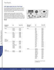
VHF/AM SINGLE CHANNEL<br />
TRANSCEIVER<br />
MODEL TiL-92-SC<br />
(<strong>TSC</strong>-<strong>4100</strong>/<strong>4200</strong>/<strong>4300</strong>)<br />
25 WATT TRANSCEIVER P/N 921018-1 (<strong>TSC</strong>-<strong>4100</strong>)<br />
15 WATT TRANSCEIVER P/N 921018-2 (<strong>TSC</strong>-<strong>4200</strong>)<br />
7 WATT TRANSCEIVER P/N 921018-3 (<strong>TSC</strong>-<strong>4300</strong>)<br />
Installation and<br />
Operating Instructions<br />
Til Document No.<br />
92RE125<br />
Rev. H<br />
September 2002<br />
Technisonic Industries Limited<br />
240 Traders Blvd., Mississauga, Ontario L4Z 1W7 Tel:(905)890-2113 Fax:(905)890-5338<br />
web site: www.til.ca
WARNING<br />
Do not make physical contact with antenna when transmitter is on. This unit can produce up to 30 watts of<br />
power (depending on configuration) when transmitting.<br />
CAUTION<br />
This unit contains static sensitive devices. Wear a grounded wrist strap and/or conductive gloves when<br />
handling printed circuit boards.<br />
WARRANTY INFORMATION<br />
The rack mounted Single Channel Transceiver, Model 92-SC series is under warranty for one year from date<br />
of purchase. Failed units caused by defective parts, or workmanship should be returned to:<br />
Technisonic Industries Limited<br />
250 Watline Avenue<br />
Mississauga,<br />
Ontario L4Z 1P4<br />
Amherst, NY<br />
Tel: (905) 890-2113 Tel: (716) 691-0669<br />
Fax: (905) 890-5338<br />
A Page
REVISIONS<br />
REV PAGE DESCRIPTION DATE APPROVED<br />
G<br />
2-11<br />
2-13<br />
R6 functional description revised,<br />
formerly incorrect.<br />
R6 description revised, formerly<br />
incorrect.<br />
23/6<br />
2000<br />
23/6/<br />
2000<br />
R.R.<br />
H<br />
1-1<br />
1-2<br />
Changes to description in para. 1.2<br />
To include information on new dual<br />
conversion receiver.<br />
2-9<br />
Note at bottom of page regarding 2-<br />
wire only capability of RJ-11.<br />
2-12<br />
Correct R22 - CW rotation direction<br />
will decrease level.<br />
3-6<br />
Changes to para.3.4.2 regarding<br />
squelch knob adjustment for dual<br />
conversion receiver.<br />
19/9/<br />
2002<br />
R.R.
TABLE OF CONTENTS<br />
Paragraph Title Page<br />
SECTION 1<br />
GENERAL DESCRIPTION<br />
1.1 Introduction ........................................................... 1-1<br />
1.2 Description ........................................................... 1-1<br />
1.2.1 Transceiver Module .................................................... 1-2<br />
1.2.2 Power Supply Modules - P/N’s 922079-1,922083-1 .......................... 1-2<br />
1.2.3 RF Amplifier Modules - Models PA-15, PA-25 ............................... 1-2<br />
1.2.4 Mother Board - P/N 923056-2 ........................................... 1-2<br />
1.2.5 Remote Control Boards................................................. 1-2<br />
1.2.6 Crystal Filter (Option 1) ................................................. 1-3<br />
1.2.7 RF Isolator ........................................................... 1-3<br />
1.3 Modes of Operation .................................................... 1-3<br />
1.3.1 Local/Remote Operation ................................................ 1-3<br />
1.3.1.1 Conference Audio ...................................................... 1-4<br />
1.3.2 AC and DC Operation .................................................. 1-4<br />
1.4 Technical Summary.................................................... 1-4<br />
SECTION 2<br />
PREPARATION FOR USE AND STORAGE<br />
2.1 Introduction ........................................................... 2-1<br />
2.2 Disassembly/Assembly ................................................. 2-1<br />
2.2.1 Remove/Replace Cover Assembly ........................................ 2-1<br />
2.2.2 Remove/Replace Transceiver Module ..................................... 2-1<br />
2.2.3 Remove/Replace Memory Set Board Module A5A1 .......................... 2-3<br />
2.2.4 Remove/Replace Control Board .......................................... 2-3<br />
2.2.5 Remove/Replace Crystal Filter Board, P/N 923069 ........................... 2-5<br />
2.3 Channel Frequency Selection ............................................ 2-5<br />
2.3.1 Introduction ........................................................... 2-5<br />
2.3.2 Frequency Range ...................................................... 2-5<br />
2.3.3 Pre-Programming Channel Frequency .................................... 2-5<br />
2.3.4 Offset Frequency Set ................................................... 2-6<br />
2.4 Remote Operation Set Up ............................................... 2-9<br />
2.4.1 Remote Control Board P/N 923051-1 ..................................... 2-10<br />
2.4.2 Remote Control Board P/N 943180-1 ..................................... 2-11<br />
2.5 Optional Loudspeaker, Headphone Installation ............................. 2-14<br />
2.5.1 External Loudspeaker ................................................. 2-14<br />
2.5.2 Headset ............................................................ 2-14<br />
2.6 Transceiver Adjustments and Settings .................................... 2-14<br />
2.7 Operational Check .................................................... 2-14<br />
2.8 Storage ............................................................. 2-14<br />
i
TABLE OF CONTENTS (Continued)<br />
Paragraph Title Page<br />
SECTION 3<br />
OPERATING INSTRUCTIONS<br />
3.1 Introduction ........................................................... 3-1<br />
3.2 Installation............................................................ 3-1<br />
3.3 Operator's Switches, Controls and Indicators ................................ 3-1<br />
3.4 Operating Instructions .................................................. 3-5<br />
3.4.1 Transmitter Operation (Local Mode) ....................................... 3-5<br />
3.4.2 Receiver Operation (Local Mode) ......................................... 3-6<br />
3.4.3 Switching OFF ........................................................ 3-6<br />
3.4.4 External DC Operation.................................................. 3-7<br />
LIST OF TABLES<br />
Table No. Title Page<br />
1-1 <strong>TSC</strong>-<strong>4100</strong>/<strong>4200</strong>/<strong>4300</strong> Configurations ........................................ 1-1<br />
1-2 92-SC Leading Particulars . . . .............................................. 1-5<br />
2-1 Frequency Selection MHz . . . .............................................. 2-7<br />
2-2 Frequency Selection KHz . . . .............................................. 2-8<br />
2-3 Remote Control Connector Functions ....................................... 2-9<br />
2-4 Remote Control Board P/N 923051-1 Settings ............................... 2-10<br />
2-5 Remote Control Board P/N 943180-1 Settings ............................... 2-11<br />
3-1 Operator's Switches, Controls and Indicators .................................. 3-3<br />
LIST OF ILLUSTRATIONS<br />
Figure No. Title Page<br />
1-1 VHF/AM Single Channel Transceiver ........................................ 1-1<br />
2-1 Single Channel Transceiver - Internal View ................................... 2-2<br />
2-2 Single Channel Memory Set Board - Module A5A1 ............................. 2-4<br />
2-3 Remote Control Board P/N 923061-1 ....................................... 2-12<br />
2-4 Remote Control Board P/N 923051 Series and 923082-1 ...................... 2-13<br />
2-6 Transceiver Adjustments and Settings ...................................... 2-15<br />
3-1 Single Channel Transceiver Controls and Indicators . . . ......................... 3-2<br />
ii
SECTION 1<br />
GENERAL DESCRIPTION<br />
1.1 INTRODUCTION<br />
This publication provides general information on the VHF/AM Single Channel Transceivers, Model<br />
TiL-92-SC, Part Nos. 921018-1, 921018-2, and 921018-3 manufactured by Technisonic Industries<br />
Limited. These units are also referred to by Item No.'s <strong>TSC</strong>-<strong>4100</strong>, <strong>TSC</strong>-<strong>4200</strong> and <strong>TSC</strong>-<strong>4300</strong><br />
respectively. This document covers the configuration of this equipment that utilizes either of the<br />
following remote control cards; p/n’s 923051-1 (standard) or 943180-1 (supplied upon request).These<br />
cards allow the transceiver to be remotely controlled over 600 ohm dedicated lines using a variety of<br />
keying methods.<br />
The Model TiL-92-SC Transceivers are simplex, single channel, fixed frequency transceivers<br />
operating over the frequency range of 117.975 MHz to 138.000 MHz. These units are intended for<br />
base station operation in an air traffic environment. These systems can operate from AC power or<br />
external DC power in local and remote operating modes.<br />
1.2 DESCRIPTION<br />
The three rack mounted transceiver configurations are based on the Model 90-6R pre-programmable<br />
transceiver configured for 7 Watt, 15 Watt or 25 Watt operation. All systems can be configured for 2<br />
Wire and 4 Wire remote operation with a variety of remote keying methods (with 923051-1 standard<br />
card). Each configuration consists of a Power Supply Module, Mother Board, and a Remote Control<br />
Board. The 15 Watt and 25 Watt configurations also consist of an RF Amplifier Module.<br />
To improve the rejection of interfering signals, dual conversion receiver technology has been<br />
incorporated on the Transmitter/Receiver (Module A1) board used in Technisonic VHF/AM base<br />
stations. The second IF is 455kHz using a ceramic filter, which is immune to high energy<br />
ringing. The dual conversion module also has a second local oscillator, second mixer and<br />
ceramic filter. The first local oscillator is the original VCO.<br />
The dual conversion receiver board, P/N 003494-1 was implemented into TBS and <strong>TSC</strong> series base<br />
stations starting in January 2001. An option label on the chassis will indicate OPTION 94 if the dual<br />
conversion board is installed. It is possible to retro-fit the dual conversion receiver/transmitter board<br />
into older <strong>TSC</strong>/TBS series base station employing the single conversion board. Please contact<br />
Technisonic for availability of an exchange board.<br />
Note: If a new A1 Module has been retrofitted the squelch circuit must be aligned for the receiver<br />
squelch to operate correctly.<br />
The dual conversion receiver’s squelch knob must be rotated significantly more clockwise (4 o’clock<br />
position) to obtain the same squelch setting (3uV) as a single conversion receiver’s squelch knob set<br />
to the 12 o’clock (straight up) position.<br />
If the dual conversion receiver’s squelch knob is set to the 12 o’clock position, signals with a level<br />
greater than 0.5uV will open the squelch. At most airports this will not be an adequate level of<br />
squelch. Please be aware of this squelch knob adjustment variance when setting and/or<br />
comparing squelch levels of dual conversion vs. single conversion base stations.<br />
An optional RF Crystal Filter which provides higher receiver selectivity is available. These filters can<br />
be ordered to provide either an additional 20dB (4 dB loss sensitivity) or 40dB (7 dB loss) of<br />
selectivity. An RF Isolator which provides unidirectional coupling to the antenna in multiple transmitter<br />
configurations is now standard. Refer to Table 1-1 for system configuration details.<br />
1-1
TABLE 1-1 <strong>TSC</strong>-<strong>4100</strong>/<strong>4200</strong>/<strong>4300</strong> CONFIGURATIONS<br />
System Motherboard w/<br />
25 pin connector<br />
AC Power<br />
supply<br />
module<br />
RF Amplifier<br />
Remote<br />
Control Cards<br />
<strong>TSC</strong>-<strong>4300</strong><br />
<strong>TSC</strong>-<strong>4200</strong><br />
<strong>TSC</strong>-<strong>4100</strong><br />
923056-2<br />
923056-2<br />
923056-2<br />
922079-1<br />
922083-1<br />
922083-1<br />
Not required<br />
Model PA-15<br />
Model PA-25<br />
P/N 923051-1<br />
or<br />
P/N 943180-1<br />
(upon request)<br />
1.2.1 Transceiver Module<br />
The Single Channel Transceiver is based on Transceiver Model 90-6R. The transceiver module is a<br />
low power VHF/AM transceiver which can transmit or receive on independent, pre-programmable<br />
synthesized frequencies, with 25kHz channel spacing in the frequency range 117.975 MHz to 138.000<br />
MHz. The single channel memory set board, module A5A1 is mounted external to the 90-6R<br />
transceiver module to facilitate ease of frequency programming. Refer to above paragraph fro details<br />
on new dual conversion receiver/transmitter A1 module.<br />
1.2.2 Power Supply Modules - P/N’s 922079-1, 922083-1<br />
The Power Supply Modules provide the DC supply voltage to the transceiver and linear amplifier, and<br />
houses a battery charger which can provide charging and trickle charging to external rechargeable<br />
batteries. P/N 922079-1 is for use in the 7 Watt configurations, P/N 922083-1 is for use in the 15 Watt<br />
configurations and the 25 Watt configurations.<br />
1.2.3 RF Amplifier Modules - Models PA-15, PA-25<br />
The RF Amplifier modules provide 15 Watt (Model PA-15) or 25 Watt (Model PA-25) power<br />
output. The RF Amplifiers are fed by the 7 Watt RF output from the transceiver module. An<br />
internal mounted RF Relay bypasses the RF Amplifier when in receive mode.<br />
1.2.4 Mother Board, p/n 923056-2<br />
Mother Board, p/n 923056-2 is supplied with the two available remote control cards and supports both<br />
a 25 pin “D” and 9 pin Positronics remote connectors on the back of the transceiver chassis. A RJ11<br />
style connector is also provided which supports only 2-wire audio signals. The Mother Board provides<br />
all interconnection between the three external remote control connectors, RF Amplifier Module, Power<br />
Supply, Remote Control Board, and Transceiver. The Remote Control Boards, RF Isolator and all<br />
internal fuses are mounted on the Mother Board.<br />
1.2.5 Remote Control Boards<br />
1. Line Interface Board P/N 923051-1<br />
Provides remote control transceiver operation on 2 wire or 4 wire 600 ohm lines. This board can be<br />
configured to key the transmitter using a 2175 Hz* continuous tone (see below), plus/minus DC<br />
1-2
Voltages, ground keying and internal or external DC (15 mA) current loop keying. Transmit and<br />
Receive audio is user selectable for two wires or four wires. *Crystals for tone frequencies other than<br />
2175 Hz may be obtained by special order (ie/2380 Hz).<br />
2. Line Interface Board P/N 943180-1<br />
Provides remote control transceiver operation on 2 wire dedicated 600 ohm lines utilizing the EIA<br />
multi-tone keying format found in the Land Mobile Industry. A high level 2175 tone followed by a 1950<br />
Hz guard tone and then a low level 2175 Hz continuous tone is utilized to key the transceiver. The<br />
943180-1 board can also be jumper strapped for standard aeronautical 2175 Hz continuous tone<br />
operation. DC (15mA) current loop and ground keying is also supported. However this board does not<br />
support 4 wire operation.<br />
NOTE<br />
P/N 923051-1 is the default board supplied in all units. The EIA multi-tone board<br />
P/N 943180-1 must be special ordered. To determine which remote card your 92-SC<br />
has installed the Configuration label on the side of the rack mount chassis should be<br />
consulted.<br />
1.2.6 Crystal Filter Board Assembly P/N 923069-1 (Option 1)<br />
The Crystal Filter is a 25 KHz bandpass filter which provides additional selectivity during receive<br />
operation. The filter provides 5 dB (MAX) attenuation of RF signals ± 7.5 KHz from the receive<br />
frequency and 20 dB (MIN) attenuation of RF signals ± 50.0 KHz from the receive carrier frequency.<br />
Loss in sensitivity is about 4 dB. A higher 40dB attenuation crystal filter can also be ordered. Loss<br />
in sensitivity is about 7 dB. All crystal filters are cut to the required frequency and require 6-8 weeks<br />
lead time. This item is interchangeable in the field. Refer to Paragraph 2.2.5 for replacement<br />
instructions. If no crystal filter option is ordered, jumper board assembly P/N 923074-1 is installed.<br />
1.2.7 RF Isolator<br />
The RF Isolator is a broadband (118 MHz - 138 MHz) RF directional coupler. The RF Isolator provides<br />
20 dB of isolation between the antenna and RF Amplifier while providing 0.7 dB (Max.) insertion loss.<br />
The RF isolator is located on the motherboard and is now provided in all 92-SC equipment.<br />
1.3 MODES OF OPERATION<br />
1.3.1 Local/Remote Operation<br />
NOTE<br />
Local operation is not disabled when operating in Remote mode and Remote operation is not<br />
disabled when operating in Local mode. The two operating modes operate in parallel.<br />
1. LOCAL OPERATION - In local operation, voice audio, and keying (PTT) functions are<br />
routed from the microphone (not supplied) to the transceiver. Receive audio is routed<br />
to the internal loudspeaker and phone jack located on the front panel.<br />
2. REMOTE OPERATION - In Remote operation, transmit audio, keying (PTT), and receive<br />
audio functions are routed over land lines to the 600 ohm remote inputs. Internal jumpers can<br />
be set for ±DC, ground, or tone transmitter keying, and to provide a DC squelch signal and<br />
RF Output Power signal depending on the remote control board installed. Receive audio is<br />
1-3
outed to the internal loudspeaker and is adjustable by the volume control. Transmit audio<br />
is also routed to the internal loudspeaker at an internally adjustable preset level (see<br />
conference audio).<br />
1.3.1.1 Conference Audio (Optional)<br />
NOTE: This feature is only provided upon special order. The component (R7)<br />
discussed below is left unpopulated on standard configuration radios.<br />
Conference Audio provides the operator with Tx voice on the transceiver speaker when the<br />
transmitter is remotely keyed from another location. The audio level of the transmit audio is<br />
internally adjustable from 0.0W to 0.5W of audio output. The adjustment is performed via<br />
rotation of the potentiometer R7 (see Figure 2-5 for location), which is accessible from the<br />
top of the transceiver after removing the top dust cover of the unit.<br />
NOTE: The transmit audio level can be increased by rotating potentiometer R7 clockwise and<br />
decreased by counterclockwise rotation. If further adjustment of conference audio is required,<br />
the top cover of the transceiver module must be removed to gain access to potentiometer<br />
R63, located on the Audio Interface Module, A3 (see Figure 2-5 for location).<br />
1.3.2 AC and DC Operation<br />
The unit can be operated by external 120 VAC or external 28 VDC (13.7 VDC for 7W configurations).<br />
The AC power supply can also be set to allow operation on 240 VAC.<br />
1. AC OPERATION - During AC operation, the unit can charge and trickle charge external<br />
batteries via the external connectors mounted on the rear panel of the unit. Refer to<br />
section 3 for remote connector pin details regarding DC operation.<br />
2. DC OPERATION - The unit can be operated from an external DC supply within the range of<br />
21.6 Vdc to 30 Vdc for 15 watt and 25 watt configurations and within the range of 11.5 Vdc<br />
to 15.0 Vdc for 7 watt configurations.<br />
1.4 TECHNICAL SUMMARY<br />
A summary of electrical, operational, mechanical and physical characteristics of the Single<br />
Channel Transceivers are provided in Table 1-2.<br />
1-4
TABLE 1-2<br />
92-SC LEADING PARTICULARS<br />
POWER REQUIREMENTS:<br />
7 Watt Transceiver<br />
AC Input Voltage/Current ........................... 100 to 132 VAC @ 1.0 Amp<br />
DC Input Voltage/Current ...................... 11.5 VDC to 15 VDC @ 3.5 Amp<br />
15 Watt Transceiver<br />
AC Input Voltage/Current ........................... 100 to 132 VAC @ 1.5 Amp<br />
DC Input Voltage/Current ...................... 21.6 VDC to 30 VDC @ 4.0 Amp<br />
25 Watt Transceiver<br />
AC Input Voltage/Current ........................... 100 to 132 VAC @ 2.0 Amp<br />
DC Input Voltage/Current ...................... 21.6 VDC to 30 VDC @ 7.5 Amp<br />
POWER OUTPUT:<br />
7 Watt Transceiver..................................................... 5-10 Watts<br />
15 Watt Transceiver................................................... 10-20 Watts<br />
25 Watt Transceiver................................................... 20-30 Watts<br />
Microphone Compression Range .....................................................35 dB<br />
Battery Charger Voltage & Current .................................... 27.5 Vdc, 3.5 Amps MAX<br />
REMOTE CONTROL BOARD, P/N 923051-1 specifications:<br />
Remote Audio Input ............................... 2 or 4 wire (selectable), balanced 600 Ω lines<br />
Remote Tx Timeout ..................................................... 30 to 300 seconds<br />
Tone Keying:<br />
Impedance ............................................. 600 Ω floating with respect to ground<br />
Tx Control Tone........................................................ 2175 Hz, standard<br />
Tx Tone Input Level .......................................................... 0 to -40 dBm<br />
Tx Tone Control Response Time ............................................
TABLE 1-2<br />
92-SC LEADING PARTICULARS (Continued)<br />
TRANSCEIVER MODULE:<br />
Dimensions & Weight:<br />
Width ....................................................... 216 mm (8.5 in) MAX<br />
Height ....................................................... 70 mm (2.75 in) MAX<br />
Depth ..................................................... 260 mm (10.25 in) MAX<br />
Weight .................................................... 1.8 Kg (3 lb 15 oz) MAX<br />
TRANSMITTER:<br />
Power Output ......................................................... 5-10 Watts<br />
Audio Input .................................................. 0.05 Vrms to 2.0 Vrms<br />
Speech Processor Dynamic Range ............................................35 dB<br />
Modulation ............................................................ 95% MAX<br />
Audio Distortion @ 90% mod (Low Power) .................................. 10% MAX<br />
Audio Distortion @ 90% mod (with Linear Amplifier at High Power) ............... 15% MAX<br />
Audio Frequency Response .............................. 300 Hz to 2,500 Hz, +1, -3 dB<br />
Spurious Emissions ............................................. 60 dB below carrier<br />
Hum and Noise ....................................... 45 dB below modulated carrier<br />
RECEIVER:<br />
RF Input Impedance ........................................... 50Ω, VSWR 2:1 MAX<br />
Sensitivity (12 dB SINAD) @ 1 KHz 30% Mod .................................1.5 µvolts<br />
Selectivity, 25 KHz Channel Spacing:<br />
6 dB Bandwidth ........................................Greater Than 14 KHz<br />
80 dB Bandwidth ......................................... Less Than 50 KHz<br />
Adjacent Channel Selectivity ...................................... Greater Than 85 dB<br />
Spurious Response Attenuation ....................................Greater than 95 dB<br />
Frequency Stability (-40EC to +55EC).................................. ±1,000 Hz MAX<br />
RF AGC (5 µvolts to 1 volt) ......................... Audio Level change of less than 3 dB<br />
Intermodulation:<br />
Ultimate Sensitivity ...................................................70 dB<br />
30 µvolts ...........................................................45 dB<br />
300 µvolts ..........................................................30 dB<br />
Unwanted Radiation .....................................Less than 80 µvolts into 50 Ω<br />
Hum & Noise @ 1mV RF 30% MOD ...........................................40 dB<br />
Loudspeaker Output ..............................................3 W MAX<br />
Phone Output ........................................... 100 mW into 600 Ω<br />
Audio Distortion 1mV RF Input, 30% MOD ............................. 3% MAX<br />
Audio Distortion 1mV RF Input, 90% MOD.................................... 5% MAX<br />
Audio Output Limiting................................Less than 1 dB @30 to 100% MOD<br />
Audio Frequency Response 300 Hz-2500 Hz ................................. +1 -3 dB<br />
Audio Acquisition Time .......................................... Less than 50 msecs<br />
Audio Squelch Characteristics:<br />
Squelch Type .....................................Noise and Carrier Operated<br />
Carrier Operated Squelch .................................... Adjustable 2 to 15 µvolts<br />
1-6
SECTION 2<br />
PREPARATION FOR USE AND STORAGE<br />
2.1 INTRODUCTION<br />
This section provides the information required for custom configuration and storage of the<br />
Single Channel Transceiver. Custom system configuration includes customizing remote control<br />
board functions, and Transmit/Receive frequency selection.<br />
CAUTION: Antenna must be connected to transceiver before transmitting or permanent damage to<br />
the output stage may occur.<br />
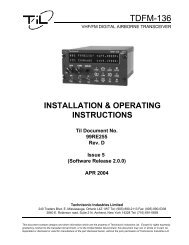
2.2 DISASSEMBLY/ASSEMBLY (Refer to Figure 2-1)<br />
2.2.1 Remove/Replace Top Dust Cover Assembly<br />
REMOVAL<br />
(1) Remove and retain twelve screws securing top dust cover to the 19" rack chassis.<br />
(2) Please note the location of the three longer screws which travel through the heatsink<br />
shims rivetted to the inside of the top cover.<br />
(3) Lift cover clear of chassis to expose internal view of transceiver as shown in Figure<br />
2-1.<br />
REPLACEMENT<br />
(1) Position top cover on chassis.<br />
(2) Position one screw in each corner of the top cover mounting holes. Place the three<br />
longer screws into their correct holes located over the internal transceiver module.<br />
(3) Secure cover to chassis with remaining screws.<br />
2.2.2 Remove/Replace Transceiver Module<br />
REMOVAL<br />
(1) Remove dust cover as described in paragraph 2.2.1.<br />
(2) Disconnect RF and DC connectors from rear of transceiver module.<br />
(3) Remove and retain the screws securing the top cover of the internal transceiver module.<br />
(4) Remove and retain two screws and two washers securing flat cable to the side of the<br />
transceiver module and disconnect the flat cable. Disconnect the flat cable running out of the<br />
transceiver module at the connector on the external memory set board.<br />
(5) Remove and Retain four countersunk screws securing transceiver module to front<br />
panel.<br />
2-1
Figure 2-1<br />
Single Channel Transceiver - Internal View<br />
2-2
(6) Move the transceiver module slightly back from the front panel and disconnect the flat<br />
cable connecting the front panel assembly to the transceiver module, audio interface<br />
board A3. The connector is located on the A3 board.<br />
(7) Lift transceiver module clear of chassis.<br />
REPLACEMENT<br />
(1) Position the transceiver module into the chassis. While holding the transceiver module<br />
slightly back from the front panel, re-connect the flat cable from the front panel to the<br />
A3 board in the transceiver module.<br />
(2) Position and secure transceiver module to front panel with four countersunk screws.<br />
(3) Re-connect flat cable to transceiver module. Secure flat cable to the side of transceiver<br />
module with two screws and two washers. Connect flat cable running out of the transceiver<br />
module to the external memory set board. Connect DC and RF connectors to rear of<br />
transceiver module.<br />
(4) Replace and secure the top cover of the transceiver module with the screws removed in step<br />
(3) of the REMOVAL instructions. Replace top dust cover as described in paragraph 2.2.1.<br />
2.2.3 Remove Replace External Single Channel Memory Set Module A5A1<br />
REMOVAL<br />
(1) Remove dust cover as described in paragraph 2.2.1, remove top cover of transceiver<br />
module.<br />
(2) Disconnect the two crystal filter co-axial cable leads for jumper J2/P3 on the Rx/Tx<br />
module A1, located in the transceiver module.<br />
(3) Remove and retain four screws securing Memory Set Board, Module A5A1 "piggy back" to<br />
the standoffs on the power supply cover. (See Figure 2-1 for location).<br />
REPLACEMENT<br />
(1) Secure the Memory Set Module to the stand-offs located on the power supply cover<br />
by the four screws. Re-connect coaxial leads for RF crystal filter.<br />
2.2.4 Remove/Replace Control Board<br />
REMOVAL<br />
(1) Remove dust cover as described in paragraph 2.2.1.<br />
CAUTION<br />
Care must be taken when removing or replacing Control Board to avoid<br />
damage to Motherboard Connector Pins.<br />
(2) Remove and retain four screws securing Control Board "piggy back" to the Mother<br />
Board standoffs. Remove Control Board from Mother Board.<br />
2-3
Figure 2-2<br />
Single Channel Memory Set Board<br />
Module A5A1 - with Crystal Filter Option<br />
2-4
REPLACEMENT<br />
(1) Align the two female connectors on the control board with the male connectors on the Mother<br />
Board using the four mounting holes and standoffs as a guide. Secure control board to the<br />
Mother Board standoffs with four screws and washers.<br />
(2) Replace dust cover as described in paragraph 2.2.1.<br />
2.2.5 Remove/Replace Crystal Filter Board, p/n 923069 or Jumper Board, p/n 923074<br />
REMOVAL<br />
(1) Remove dust cover of unit as described in Paragraph 2.2.1.<br />
(3) Remove and retain the four screws securing the crystal filter board, p/n 923069-1 (or jumper<br />
Board, p/n 923074) to the standoffs on the external frequency set module A5A1. Pull the<br />
crystal filter board assembly straight up to avoid damaging the connector pins.<br />
REPLACEMENT<br />
(1) Align the pins on the bottom of the crystal filter board with their sockets on the memory set<br />
board. Push the crystal filter board straight down until it rests on the memory set board<br />
standoffs and secure with the four mounting screws.<br />
(2) Connect Module A5A1 co-axial jumper leads to jumper J2/P3 on Rx/Tx Module A1, if not<br />
already connected. Either a crystal filter board, p/n 923074 or a jumper board, p/n 923074<br />
must be installed and the A5A1 co-axial jumper leads connected to J2/P3 on the Rx/Tx<br />
Module A1, for the receiver to work.<br />
NOTE: Make certain that the memory set board, module A5A1 is programmed to the same<br />
operating frequency as the crystal filter board assembly. If no crystal filter board assembly<br />
(option) is installed, jumper board assembly P/N 923074-1 must be installed.<br />
2.3 CHANNEL FREQUENCY SELECTION<br />
2.3.1 Introduction<br />
Before programming a new operating frequency, verify operation on the original frequency.<br />
2.3.2 Frequency Range<br />
The operating frequency may be programmed over the frequency range 117.975 MHz to 138.000<br />
MHz with 25kHz channel spacing.<br />
2.3.3 Pre-programming Channel Frequency<br />
FREQUENCY SELECTION MHz.<br />
Refer to Table 2-1 Frequency Selection MHz. Using the OPERATING FREQUENCY (MHz) column,<br />
find the desired frequency in MHz. Cross-refer to the JUMPER LOCATION column, and install the<br />
jumper as required.<br />
2-5
FREQUENCY SELECTION KHz<br />
Refer to Table 2-2, Frequency Selection kHz. Using the OPERATING FREQUENCY kHz column,<br />
find the portion of the desired frequency in kHz. Cross-refer to the JUMPER LOCATION column, and<br />
install the jumpers in the locations as required.<br />
2.3.4 Offset Frequency Set<br />
(A)<br />
Jumper J15, located on the single channel memory set board, module A5A1 selects<br />
the frequency offset as follows:<br />
(1) If J15 is not installed, frequency offset is inhibited.<br />
(2) If J15 is installed in the Rx position, the transmitted frequency will be higher<br />
than the receive frequency.<br />
(3) If J15 is installed in the Tx position, the transmitted frequency will be lower<br />
than the receive freqeuncy.<br />
(B) Trim capacitors C16 and C37, accessible from the bottom of the unit (see Figure 2-5),<br />
are used to accurately adjust the transmit and receive frequency.<br />
For the Tx frequency to be higher than the receive frequency, proceed as follows:<br />
(1) Set jumper J15 on the memory set board to Rx position.<br />
(2) Key PTT and set the transmitted frequency (without modulation) by rotating<br />
C16* to the desired Tx frequency. *(Revised from C37 in Rev.D document).<br />
(3) Set jumper J15 to Tx position. Key PTT and without modulation set the transmitted<br />
frequency by rotating trim capacitor, C37 to the desired Rx frequency.<br />
(4) Set jumper J15 to the Rx position, key the PTT and without modulation, verify<br />
that the transmitted frequency is the desired Tx frequency. If not, repeat steps<br />
2, 3 and 4.<br />
For the Tx frequency to be lower than the the Rx frequency proceed as follows:<br />
(1) Set jumper J15 to the Rx position. Key the PTT and without modulation set the<br />
transmitted frequency, rotating trim capacitor C16 to the desired Rx frequency.<br />
Release PTT.<br />
(2) Set Jumper J15 to the Tx position. Key the PTT and without modulation set the<br />
transmitted frequency by rotating trim capacitor C37 to the desired transmit<br />
frequency. Release PTT.<br />
(3) Set jumper J15 to thr Rx position. Key the PTT and without modulation, verify that<br />
the transmitted frequency is the desired receive frequency. If not repeat steps 1, 2,<br />
and 3. If it is, release the PTT and set jumper J15 to the Tx position, thus completing<br />
the frequency tuning.<br />
2-6
TABLE 2-1 FREQUENCY SELECTION MHz<br />
OPERATING<br />
FREQUENCY<br />
(MHz)<br />
JUMPER LOCATION<br />
20 Mhz 10 MHz 8 MHz 4 MHz 2 MHz 1 MHz<br />
117<br />
0<br />
1<br />
0<br />
1<br />
1<br />
1<br />
118<br />
0<br />
1<br />
1<br />
0<br />
0<br />
0<br />
119<br />
0<br />
1<br />
1<br />
0<br />
0<br />
1<br />
120<br />
1<br />
0<br />
0<br />
0<br />
0<br />
0<br />
121<br />
1<br />
0<br />
0<br />
0<br />
0<br />
1<br />
122<br />
1<br />
0<br />
0<br />
0<br />
1<br />
0<br />
123<br />
1<br />
0<br />
0<br />
0<br />
1<br />
1<br />
124<br />
1<br />
0<br />
0<br />
1<br />
0<br />
0<br />
125<br />
1<br />
0<br />
0<br />
1<br />
0<br />
1<br />
126<br />
1<br />
0<br />
0<br />
1<br />
1<br />
0<br />
127<br />
1<br />
0<br />
0<br />
1<br />
1<br />
1<br />
128<br />
1<br />
0<br />
1<br />
0<br />
0<br />
0<br />
129<br />
1<br />
0<br />
1<br />
0<br />
0<br />
1<br />
130<br />
1<br />
1<br />
0<br />
0<br />
0<br />
0<br />
131<br />
1<br />
1<br />
0<br />
0<br />
0<br />
1<br />
132<br />
1<br />
1<br />
0<br />
0<br />
1<br />
0<br />
133<br />
1<br />
1<br />
0<br />
0<br />
1<br />
1<br />
134<br />
1<br />
1<br />
0<br />
1<br />
0<br />
0<br />
135<br />
1<br />
1<br />
0<br />
1<br />
0<br />
1<br />
136<br />
1<br />
1<br />
0<br />
1<br />
1<br />
0<br />
137<br />
1<br />
1<br />
0<br />
1<br />
1<br />
1<br />
138<br />
1<br />
1<br />
0<br />
0<br />
0<br />
0<br />
LEGEND: 0 = JUMPER BETWEEN CENTRE AND 0 1 = JUMPER BETWEEN CENTRE AND 1<br />
2-7
TABLE 2-2 FREQUENCY SELECTION KHz<br />
OPERATING<br />
FREQUENCY<br />
(KHz)<br />
DIODE LOCATION<br />
800 KHz 400 KHz 200 KHz 100 KHz 50 KHz 25 KHz<br />
000<br />
025<br />
050<br />
075<br />
100<br />
125<br />
150<br />
175<br />
200<br />
225<br />
250<br />
275<br />
300<br />
325<br />
350<br />
375<br />
400<br />
425<br />
450<br />
475<br />
500<br />
525<br />
550<br />
575<br />
600<br />
625<br />
650<br />
675<br />
700<br />
725<br />
750<br />
775<br />
800<br />
825<br />
850<br />
875<br />
900<br />
925<br />
950<br />
975<br />
0<br />
0<br />
0<br />
0<br />
0<br />
0<br />
0<br />
0<br />
0<br />
0<br />
0<br />
0<br />
0<br />
0<br />
0<br />
0<br />
0<br />
0<br />
0<br />
0<br />
0<br />
0<br />
0<br />
0<br />
0<br />
0<br />
0<br />
0<br />
0<br />
0<br />
0<br />
0<br />
1<br />
1<br />
1<br />
1<br />
1<br />
1<br />
1<br />
1<br />
0<br />
0<br />
0<br />
0<br />
0<br />
0<br />
0<br />
0<br />
0<br />
0<br />
0<br />
0<br />
0<br />
0<br />
0<br />
0<br />
1<br />
1<br />
1<br />
1<br />
1<br />
1<br />
1<br />
1<br />
1<br />
1<br />
1<br />
1<br />
1<br />
1<br />
1<br />
1<br />
0<br />
0<br />
0<br />
0<br />
0<br />
0<br />
0<br />
0<br />
0<br />
0<br />
0<br />
0<br />
0<br />
0<br />
0<br />
0<br />
1<br />
1<br />
1<br />
1<br />
1<br />
1<br />
1<br />
1<br />
0<br />
0<br />
0<br />
0<br />
0<br />
0<br />
0<br />
0<br />
1<br />
1<br />
1<br />
1<br />
1<br />
1<br />
1<br />
1<br />
0<br />
0<br />
0<br />
0<br />
0<br />
0<br />
0<br />
0<br />
0<br />
0<br />
0<br />
0<br />
1<br />
1<br />
1<br />
1<br />
0<br />
0<br />
0<br />
0<br />
1<br />
1<br />
1<br />
1<br />
0<br />
0<br />
0<br />
0<br />
1<br />
1<br />
1<br />
1<br />
0<br />
0<br />
0<br />
0<br />
1<br />
1<br />
1<br />
1<br />
0<br />
0<br />
0<br />
0<br />
1<br />
1<br />
1<br />
1<br />
0<br />
0<br />
1<br />
1<br />
0<br />
0<br />
1<br />
1<br />
0<br />
0<br />
1<br />
1<br />
0<br />
0<br />
1<br />
1<br />
0<br />
0<br />
1<br />
1<br />
0<br />
0<br />
1<br />
1<br />
0<br />
0<br />
1<br />
1<br />
0<br />
0<br />
1<br />
1<br />
0<br />
0<br />
1<br />
1<br />
0<br />
0<br />
1<br />
1<br />
0<br />
1<br />
0<br />
1<br />
0<br />
1<br />
0<br />
1<br />
0<br />
1<br />
0<br />
1<br />
0<br />
1<br />
0<br />
1<br />
0<br />
1<br />
0<br />
1<br />
0<br />
1<br />
0<br />
1<br />
0<br />
1<br />
0<br />
1<br />
0<br />
1<br />
0<br />
1<br />
0<br />
1<br />
0<br />
1<br />
0<br />
1<br />
0<br />
1<br />
LEGEND: 0 = JUMPER BETWEEN CENTRE AND 0 1 = JUMPER BETWEEN CENTRE AND 1<br />
2-8
2.4 REMOTE OPERATION SETUP<br />
The Procedures listed below enable the user to custom configure the unit for external remote<br />
control hardware. Refer to Table 2-3 for connector pin details on Remote Control D Connector<br />
located at rear of Single Channel Transceiver. Position Jumpers on Control board as indicated<br />
in Table 2-4 or Table 2-5 as required. Refer to Figure 2-3 and Figure 2-4 for board locations.<br />
Verify Remote Control operation in accordance with manufacturers instructions.<br />
TWO WIRE SETUP - In two wire operation, a single balanced 600 ohm pair is provided for<br />
transmit and receive audio. The transmitter can be keyed on the same pair or externally.<br />
FOUR WIRE SETUP - In four wire operation, separate balanced 600 ohm pairs are provided for<br />
transmit and receive audio. The transmitter can be keyed on the Tx audio pair or externally.<br />
DC KEYING - In ± DC keying, a positive voltage between +10 Vdc and +48 Vdc or negative voltage<br />
between -10 Vdc and -48 Vdc will key the transmitter. A DC voltage between -5 Vdc and +5 Vdc will<br />
not key the transmitter.<br />
TONE KEYING - In Tone keying a tone of 2175 Hz or 2380 Hz (Optional) can be used to key<br />
the transmitter. Tone sensitivity is adjustable from -40 dBm to 0 dBm.<br />
GROUND KEYING - In Ground Keying the transmitter is keyed by shorting the control point<br />
(landline or External Keying) to chassis ground<br />
CURRENT LOOP KEYING - In Current Loop keying, an internal or external current source (15<br />
mA) is used to key the transmitter<br />
EIA TONE KEYING - The EIA multi-tone keying format is found in the Land Mobile Industry.<br />
A high level 2175 Hz tone followed by a 1950 Hz guard tone then a low level 2175 Hz continuous tone<br />
is utilized to key the transceiver.<br />
9 PIN<br />
NO<br />
A,B<br />
C,D<br />
H<br />
N/A<br />
K<br />
J<br />
N/A<br />
E(-),F(+)<br />
N/A<br />
N/A<br />
TABLE 2-3<br />
25 PIN<br />
NO<br />
9,21<br />
10,22<br />
12,24<br />
8<br />
13<br />
1,2,14,15<br />
25<br />
23(-),11(+)<br />
20<br />
3,4,5,6,7,16,17,<br />
18, 19<br />
REMOTE CONTROL CONNECTOR FUNCTIONS<br />
Connector Pin Functions<br />
4 Wire Tx Audio Line or 2 Wire Rx/Tx Audio Line (600 Ω)<br />
4 Wire Rx Audio Line (600 Ω)<br />
External DC In (+24 Vdc)<br />
AGC<br />
Single Line Keying (PTT)<br />
Ground<br />
Squelch<br />
Carrier Control<br />
RF Indicator<br />
Not Connected, allocated for future functions<br />
NOTE: A modular RJ-11 Jack is also provided on the rear of the 19" rack chassis for quick connection to the<br />
2 wire, Tx/Rx Audio. The red and green wire connections (centre pins) on the RJ-11 are connected parallel<br />
to pins 9 and 21 on the 25 pin connector. This RJ-11 jack CANNOT be used if the remote control card is set<br />
to 4-wire operation as it does not have the necessary connections.<br />
2-9
2.4.1 Two/Four Wire Remote Control Board P/N 923051-1<br />
Provides remote control base station operation on 2 wire or 4 wire, 600 ohm lines. This board can be<br />
configured to key the transmitter using a 2175 Hz tone (2380 Hz upon request), plus/minus DC<br />
Voltages, ground keying and internal or external current loop keying. Transmit and Receive audio is<br />
user selectable for two wires or four wires. Crystals for tone frequencies other than 2175 Hz or 2380<br />
Hz may be obtained by special order.<br />
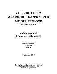
See Figure 2-3 for location of jumpers referred to in the following table. Pins are numbers<br />
increase as you go from top to bottom or left to right on the connector.<br />
TABLE 2-4 REMOTE CONTROL BOARD P/N 923051-1 SETTINGS<br />
CONTROL<br />
J1<br />
J2<br />
J3<br />
J7<br />
J6<br />
SW1<br />
SW2<br />
Y1,Y2<br />
R7<br />
R22<br />
R25<br />
R44<br />
R10<br />
FUNCTION<br />
Jumper Pin 1 and Pin 2 for DC Current Loop Keying<br />
Jumper Pin 2 and Pin 3 for ± DC Keying or Ground Keying.<br />
Note: SW2 must be in position 2 if Pin 2 and Pin 3 are jumpered.<br />
Jumper Pin 1 and Pin 2 for Ground Keying (Land Line).<br />
Jumper Pin 1 and Pin 4 for ± DC Keying (Land Line).<br />
Jumper Pin 2 and Pin 3 for Ground Keying (Single Key Line).<br />
Jumper Pin 3 and Pin 6 for ± DC Keying (Single Key Line).<br />
Jumper Pin 2 and Pin 5 for No Function.<br />
Jumper Pin 1 and Pin 2 for ± DC or Ground Keying.<br />
Jumper Pin 4 and Pin 5 for Tone Keying.<br />
Note: Both Options may be selected.<br />
Jumper Pin 2 and Pin 3 for No Function.<br />
Jumper Pin 5 and Pin 6 for No Function.<br />
Jumper Pin 1 and Pin 2 to enable Timeout Timer.<br />
Jumper Pin 2 and Pin 3 to disable Timeout Timer.<br />
Jumper Pin 1 and Pin 2 to for Internal Current Loop Keying.<br />
Jumper Pin 2 and Pin 3 to for External Current Loop Keying.<br />
Position 1 Selects 2 Wire Operation.<br />
Position 2 Selects 4 Wire Operation.<br />
Position 1 Selects Normal (Land Line Keying).<br />
Position 2 Selects Local (Single Line Keying).<br />
Determines Keying Tone Frequency.<br />
Sets Tx Audio IN Level (Range -18 dBm to +10 dBm).<br />
Sets Key Tone Level (Range -40 dBm to 0 dBm).<br />
Sets Rx Audio OUT Level (Range -15 dBm to +10 dBm).<br />
Sets Timeout Timer (Range 30 to 300 Seconds).<br />
Sets Receive Audio Output Balance.<br />
2-10
2.4.2 Two Wire Line Interface Board P/N 943180-1<br />
Provides remote control Base Station operation on 2 wire 600 ohm lines.Two wire Line Interface<br />
board with EIA multi-tone, standard 2175Hz continuous tone, DC keying of ground keying over audio<br />
lines. The multi-tone keying format consists of a high level 2175 tone followed by a 1950 Hz guard<br />
tone and then a low level 2175 Hz continuous tone is utilized to key the transceiver. This board will<br />
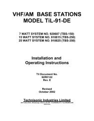
also support 15mA current loop or ground keying. Refer to Figure 2-4 for jumper locations to set<br />
functions and line level adjustments for this board. Summary of jumper settings follow. Pins are<br />
numbers increase as you go from top to bottom or left to right on the connector.<br />
Set J1 for ST (standard 2175Hz continuous) Tone keying or for EIA (multi-tone keying format).<br />
Set J2 for Tone keying function ON (left jumper position) or OFF (right jumper position).<br />
Set J3 for Time out timer OFF (left jumper position) or ON (right jumper position).<br />
See Figure 2-4 for location of jumpers and left/right orientation.<br />
TABLE 2-4 REMOTE CONTROL BOARD P/N 943180-1 SETTINGS<br />
CONTROL<br />
J1<br />
J2<br />
J3<br />
R6<br />
R24<br />
R26<br />
R41<br />
R59<br />
R64<br />
FUNCTION<br />
Jumper Pin 1 and Pin 2 for ST (standard 2175 Hz continuous) tone Keying<br />
Jumper Pin 2 and Pin 3 for EIA multi-tone Keying.<br />
Jumper Pin 1 and Pin 2 for Tone Keying.<br />
Jumper Pin 4 and Pin 5 for Current Loop (15mA DC) or Ground Keying.<br />
NOTE: Both options may be selected<br />
Jumper Pin 2 and Pin 3 to disable Tone Keying.<br />
Jumper Pin 5 and Pin 6 to disable Current Loop and Ground Keying.<br />
Jumper Pin 1 and Pin 2 to enable Timeout Timer.<br />
Jumper Pin 2 and Pin 3 to disable Timeout Timer.<br />
Tx audio level Adjustment<br />
Keying Tone Attenuator<br />
1950 Tone level Adjustment<br />
2175 Tone Level Adjustment<br />
Sets Rx Audio Level Adjustment (Range -15 dBm to +10 dBm).<br />
Sets Timeout Timer (Range 30 to 300 Seconds)<br />
2-11
Control Configuration for 2/4 Wire (+/-)DC/Ground/Tone/<br />
(Current Loop) Keying Control Board.<br />
Assembly #: 923051<br />
R7: Tx Audio SW2: Selects either Local<br />
(-25 dBm sensitivity; or Land Line Current<br />
increases clockwise).<br />
Loop Keying.<br />
R10: 2 Wire Rx Balance @ 600Ω J1: Selects DC or Current<br />
(1mV RF @ 1KHz, 30% Mod.)<br />
Loop Keying operation.<br />
R10 adjusted for minimum J2: Selects either Land Line<br />
amplitude at C6/R4 junction.<br />
(L/L) or Single Line (S/L)<br />
R22: Keying Tone and +/- DC or Ground<br />
(-30 dBm sensitivity; keying operation.<br />
decreases clockwise). J3: Selects Tone and/or +/- DC<br />
R25: Rx Audio Keying enable or disable.<br />
(-10 dBm output level; J6: Selects between Internal<br />
increases clockwise).<br />
or External Current loop<br />
R44: Time Out Timer keying (ICL/ECL).<br />
(15 to 300 sec.; J7: Keying timer<br />
90 sec. Nominal; Enable/Disable.<br />
increases clockwise). J4: Input Connector.<br />
SW1: Selects either 2 Wire J5: Output Connector.<br />
or 4 Wire operation.<br />
NOTE: Bold Italics indicate Factory default configurations.<br />
Figure 2-3 Line Interface/Remote Control Board P/N 923051-1<br />
2-12
Control Configuration for Multi-Tone<br />
Control Board.<br />
Assembly #: 943180<br />
R6: Tx audio level adjustment (-25 dBm). J1: Standard or EIA<br />
R24: Keying Tone Attenuator. Keying tone protocol.<br />
R26: 1950 Hz tone level adjustment J2: Selects Tone and/or Current Loop/<br />
R41: 2175 Hz tone level adjustment Ground Keying enable or disable<br />
R59: Rx Audio level adjustment. J3: Selects Keying timer Enable/Disable<br />
(-10 dBm) J4: Input Connector<br />
R64: Time out timer J5: Output Connector<br />
(90 sec. default)<br />
NOTE: Bold Italics indicate Factory default configurations.<br />
Figure 2-4 Line Interface/Remote Control Board P/N 943180-1<br />
2-13
2.5 OPTIONAL LOUDSPEAKER, HEADPHONE INSTALLATION<br />
Provision is made for connection of an external loudspeaker or headphone to the<br />
jack of the transceiver, as shown in Figure 3-1.<br />
SPEAKER/PHONE<br />
2.5.1 External Loudspeaker<br />
When an external loudspeaker is to be installed, an 8-ohm nominal impedance loudspeaker should<br />
be used. The loudspeaker cable should be terminated by a 1/4 in., 3-pole telephone plug (male), with<br />
the loudspeaker connected between tip and sleeve (ground). Insert the external loudspeaker<br />
connector into the SPEAKER/PHONE jack located on the front panel of the transceiver. When the<br />
external loudspeaker is connected to the transceiver SPEAKER/PHONE jack, the internal<br />
loudspeaker is automatically disconnected.<br />
2.5.2 Headset<br />
Headset impedance should be 150 to 600 ohms. The headset cable must terminate in a 1/4<br />
in. 3-pole telephone plug (male), to mate with the SPEAKER/PHONE jack located on the front<br />
panel of the transceiver. The internal loudspeaker is automatically disconnected. Connect the<br />
headset as indicated below for receiver audio with or without transmit audio.<br />
(1) HEADSET WITHOUT TRANSMIT AUDIO - When receiver audio only without transmit<br />
audio is required, the headset should be connected between the tip and sleeve (ground)<br />
of the telephone plug.<br />
(2) HEADSET WITH TRANSMIT AUDIO - When receiver audio with transmit audio is<br />
required, the headset should be connected between the ring and sleeve (ground).<br />
2.6 TRANSCEIVER ADJUSTMENTS AND SETTINGS<br />
The locations at which certain transceiver settings and adjustments can be performed are shown in<br />
Figure 2-5. The top dust cover of the transceiver must be removed as described in paragraph 2.2.1<br />
to access the AGC, Squelch and Modulation settings. The plastic plugs must be removed prior to<br />
adjustment of the remaining settings which are accessed from the bottom of the transceiver chassis.<br />
If alignment procedures for these settings are required please consult the manufacturer or the<br />
appropriate service manual.<br />
2.7 OPERATIONAL CHECK<br />
Perform an operational check of the transceiver after all adjustments. Ensure that the transceiver<br />
operates in both the transmit and receive modes of operation, using the Operating Instructions given<br />
in Section 3 of this document and the appropriate specified operating procedures for use with the<br />
Remote Control Unit.<br />
2.8 STORAGE<br />
To store for an extended period, store unit in a dry place, in the original shipping container.<br />
2-14
Figure 2-5<br />
Transceiver Adjustments and Settings<br />
2-15
SECTION 3<br />
OPERATING INSTRUCTIONS<br />
3.1 INTRODUCTION<br />
This section includes a functional description of each switch, control, indicator and connector<br />
located on the front and rear panels of the portable transceiver, including the PRESS-TO-TALK<br />
switch located on the microphone. Operating instructions for transmit/receive and the special<br />
functions are also included.<br />
3.2 INSTALLATION<br />
The Single Channel Transceivers are designed for mounting in a 19 inch rack. An AC Line cord P/N<br />
927002-1 is supplied for connection to AC Power. A 9 Pin connector (mates with P o s i t r o n i c<br />
GM9MSCG000VL or equivalent) and a 25 Pin Connector (mates with Amphenol 17D-B-25S or<br />
equivalent) are provided for connection with external DC and 2 Wire or 4 Wire 600 ohm dedicated<br />
lines. A 50 ohm "N" Type connector is provided for connection to an external antenna. Refer to<br />
Section 2 for frequency selection and remote control setup details.<br />
(1) Mount Transceiver in 19 inch rack with 4 screws.<br />
(2) Install Microphone in Microphone (PTT) connector if required.<br />
(3) Ensure that Transceiver POWER ON/OFF switch is set to OFF.<br />
(4) Install AC line cord in AC chassis connector on rear panel.<br />
(5) Install Remote Control connector to 9 Pin or 25 Pin connector as required. (Refer to<br />
Figure 3-1 for connector pin outs.)<br />
(6) Connect antenna connector to rear panel chassis N Type connector.<br />
3.3 OPERATOR'S SWITCHES, CONTROLS AND INDICATORS<br />
A view of the front and rear panel is given in Figure 3-1. A functional description of each of<br />
the operator's switches, controls and indicators, and the microphone PRESS-TO-TALK switch,<br />
is given in Table 3-1, Operator's Switches, Controls and Indicators.<br />
3-1
Figure 3-1<br />
Single Channel Transceiver Controls and Indicators<br />
3-2
TABLE 3-1 OPERATOR'S SWITCHES, CONTROLS AND INDICATORS<br />
Item<br />
No.<br />
SWITCHES<br />
CONTROLS &<br />
INDICATORS<br />
FUNCTIONAL DESCRIPTION<br />
1 POWER ON/OFF<br />
SWITCH<br />
2 POWER ON LED<br />
INDICATOR<br />
3 SQUELCH<br />
CONTROL<br />
4 SQUELCH<br />
INDICATOR<br />
5 Tx ON<br />
AMBER LED<br />
INDICATOR<br />
6 VOLUME<br />
CONTROL<br />
7 MIC/PTT<br />
CONNECTOR<br />
A toggle switch applies the AC power to the power supply and the DC 27.5<br />
volts nominal power to the transceiver. The transceiver is switched to ON<br />
in the toggle UP position the transceiver is switched OFF in the toggle<br />
DOWN position.<br />
A GREEN LED Indicates when the POWER ON/OFF switch is set to ON<br />
and voltage is applied to the transceiver.<br />
A linear potentiometer determines the squelch threshold level. When the<br />
SQUELCH CONTROL is rotated in the counter-clockwise direction, the<br />
SQUELCH GREEN LED indicates that the squelch is connecting<br />
demodulated audio to the VOLUME control.<br />
A GREEN LED indicates the squelch circuit is connecting demodulated<br />
audio signal to the VOLUME control.<br />
An AMBER LED indicates when the transceiver is keyed by the<br />
microphone PRESS-TO-TALK (PTT) switch or remote land line, and the<br />
transceiver is operated in the Tx mode. The Tx ON AMBER LED switches<br />
OFF, when the transceiver is operated in the receive mode.<br />
A logarithmic potentiometer determines the audio level applied to the<br />
internal speaker when the transceiver is operated in the receive mode.<br />
When the SPEAKER/PHONE connector is in use the internal loudspeaker<br />
is disconnected and the VOLUME CONTROL sets the audio level applied<br />
to the external speaker or headphone.<br />
A standard 0.2 inch 3-pole jack is provided to connect a microphone with<br />
PTT to the transceiver front panel.<br />
8 TX LABEL Indicates the frequency programmed for transmit.<br />
3-3
TABLE 3-1 OPERATOR'S SWITCHES, CONTROLS AND INDICATORS (Continued)<br />
Item<br />
No.<br />
SWITCHES<br />
CONTROLS &<br />
INDICATORS<br />
FUNCTIONAL DESCRIPTION<br />
9 RX LABEL Indicates the frequency programmed for receive.<br />
10 LOUDSPEAKER An 8-ohm internal speaker reproduces the receiver audio output. The<br />
audio line is disconnected from the internal loudspeaker when the<br />
transceiver is operated in Tx mode or when the SPEAKER/PHONE<br />
connector is in use.<br />
11 SPEAKER/<br />
PHONE<br />
CONNECTOR<br />
A 3-pole connector provides interconnection to either an external<br />
loudspeaker or headphone. When in use, the internal speaker is<br />
disconnected and the VOLUME control sets the audio level applied to the<br />
external speaker or headphone.<br />
12 AC FUSE A 2.5 Amp fuse protects the Base Station power supply from power supply<br />
internal short circuit or transceiver short circuit.<br />
13 * "N" TYPE<br />
RF<br />
CONNECTOR<br />
14 *AC POWER<br />
CONNECTOR<br />
15 *9 PIN<br />
REMOTE<br />
CONTROL<br />
CONNECTOR<br />
16 *25 PIN<br />
REMOTE<br />
CONTROL<br />
CONNECTOR<br />
17 *RJ-11 REMOTE<br />
CONNECTOR<br />
A 50 ohm coaxial connector provides connection to external antenna.<br />
3 Prong AC Connector for use with AC Power Cord P/N 927002-1.<br />
9 Pin "D" type connector provides connections required for remote<br />
operation. Refer to Table 2-3 for connector details.<br />
25 Pin "D" type connector provides connections required for remote<br />
operation. Refer to Table 2-3 for connector details.<br />
RJ-11 type connector provides parallel connection to the 2-Wire Tx/Rx<br />
audio from remote/line interface board. This connector supports 2 wire<br />
operation only.<br />
* Denotes items located on rear panel.<br />
3-4
3.4 OPERATING INSTRUCTIONS<br />
NOTE<br />
Refer to appropriate Operating Instructions for use<br />
with Remote Control Unit.<br />
NOTE<br />
The following operating procedures are intended<br />
specifically for Local Operation.<br />
(1) Ensure that the microphone connector is connected to the MIC/PTT connector of the<br />
transceiver.<br />
(2) Set the SQUELCH control in the fully counter-clockwise (CCW) position.<br />
(3) Set the VOLUME control in the 12 o'clock centre position.<br />
(4) Set the POWER ON/OFF switch to "ON".<br />
(5) Verify that the FUSE BLOWN red LED is OFF.<br />
(6) Verify that the POWER ON green LED is ON.<br />
(7) Proceed to operate in the transmit mode, paragraph 3.4.1 or operate in the receive<br />
mode, paragraph 3.4.2 as required.<br />
3.4.1 Transmitter Operation (Local Mode)<br />
To operate the transceiver in the transmit mode, proceed as follows:<br />
(1) Set RF POWER switch (if applicable) to desired operating level.<br />
(2) Hold the microphone in one hand, with the upper edge of the microphone as close as<br />
possible to the upper lip.<br />
NOTE<br />
This technique activates the noise cancelling feature<br />
of the microphone. The microphone is most effective<br />
when sound is ½ inch (12.7 mm) or more away from<br />
the microphone.<br />
(3) Press and hold the PRESS-TO-TALK switch of the microphone during transmission.<br />
(4) Ensure that the Tx ON amber LED is ON.<br />
(5) Speak slowly and distinctly into the microphone using specified operating procedures<br />
during transmission.<br />
(6) When message is ended, release the PRESS-TO-TALK switch of the<br />
microphone.<br />
3-5
(7) The transceiver is now operating in the receive mode.<br />
(8) Verify that the Tx ON amber LED is OFF.<br />
3.4.2 Receiver Operation (Local Mode)<br />
To operate the transceiver in the receive mode, proceed as follows:<br />
(1) Ensure that the PRESS-TO-TALK switch on the microphone is NOT depressed, and<br />
verify that the Tx ON amber LED is OFF.<br />
(2) Verify that the correct operating frequency is indicated on the front panel. Refer to<br />
Section 4 for Channel/Frequency selection.<br />
(3) Adjust the SQUELCH control to suit local reception conditions. When the SQUELCH<br />
control is rotated in the counter-clockwise direction, the SQUELCH indicator green LED<br />
will switch to ON, indicating that the squelch circuit is connecting the demodulated<br />
audio output to the VOLUME control.<br />
Further adjustment of the SQUELCH control determines the squelch setting.<br />
IMPORTANT NOTE<br />
The dual conversion receiver’s squelch knob must be rotated significantly more<br />
clockwise (4 o’clock position) to obtain the same squelch setting (3uV) as a single<br />
conversion receiver’s squelch knob set to the 12 o’clock (straight up) position.<br />
If the dual conversion receiver’s squelch knob is set to the 12 o’clock position, signals<br />
with a level greater than 0.5uV will open the squelch. At most airports this will not be an<br />
adequate level of squelch.<br />
Recommended procedure:<br />
The squelch taper on a dual conversion receiver looks as follows:<br />
Squelch knob position Squelch setting<br />
12 o’clock 0.5uV<br />
3 o’clock 1.2uV<br />
3:30 position 2.5uV<br />
4 o’clock 3uV<br />
Fully clockwise<br />
9uV<br />
It is recommended that the squelch be set to at least 2.5uV (3:30 knob position) at busy<br />
airport locations. If ACARS signals are present on adjacent or nearby channels the<br />
squelch level should be at least 3uV (4 o’clock) to prevent ACARS bleed through.<br />
(4) The VOLUME control can then be adjusted in a clockwise direction to increase the audio<br />
level, or in a counter-clockwise direction to decrease the audio level which can be heard on<br />
the internal loudspeaker.<br />
NOTE<br />
When an external loudspeaker or headset is<br />
connected to the SPEAKER/PHONE jack of the<br />
transceiver, the internal loudspeaker is automatically<br />
disconnected. The VOLUME control will now control<br />
the audio level applied to the external loudspeaker or<br />
headset, as applicable.<br />
3-6
3.4.3 Switching OFF<br />
To switch off the transceiver:<br />
(1) Set the POWER ON/OFF on transceiver to switch to OFF.<br />
(2) Verify that all indicator LED's on the front panel are OFF.<br />
NOTE<br />
When the transceiver is switched OFF there is no<br />
current drain from external DC.<br />
3.4.4 EXTERNAL DC OPERATION<br />
(1) Set AC ON/OFF switch to OFF.<br />
(2) Refer to Table 2-3 for pin numbers and Figure 3-1 for pin locations to hook up external<br />
DC Power.<br />
NOTE<br />
Ensure that the DC source voltage does not exceed 30<br />
Vdc. The 15 watt and 25 watt units can operate within<br />
the range 21.6 Vdc to 30 Vdc. The 7 watt units can<br />
operate within the range of 11.5 Vdc to 15.0 Vdc.<br />
3-7