TSC-4100/4200/4300 - Dallas Avionics, Inc.
TSC-4100/4200/4300 - Dallas Avionics, Inc.
TSC-4100/4200/4300 - Dallas Avionics, Inc.

You also want an ePaper? Increase the reach of your titles
YUMPU automatically turns print PDFs into web optimized ePapers that Google loves.
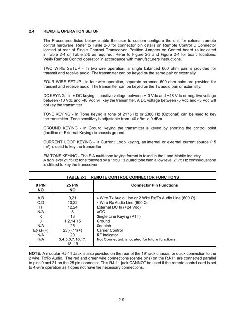
2.4 REMOTE OPERATION SETUP<br />
The Procedures listed below enable the user to custom configure the unit for external remote<br />
control hardware. Refer to Table 2-3 for connector pin details on Remote Control D Connector<br />
located at rear of Single Channel Transceiver. Position Jumpers on Control board as indicated<br />
in Table 2-4 or Table 2-5 as required. Refer to Figure 2-3 and Figure 2-4 for board locations.<br />
Verify Remote Control operation in accordance with manufacturers instructions.<br />
TWO WIRE SETUP - In two wire operation, a single balanced 600 ohm pair is provided for<br />
transmit and receive audio. The transmitter can be keyed on the same pair or externally.<br />
FOUR WIRE SETUP - In four wire operation, separate balanced 600 ohm pairs are provided for<br />
transmit and receive audio. The transmitter can be keyed on the Tx audio pair or externally.<br />
DC KEYING - In ± DC keying, a positive voltage between +10 Vdc and +48 Vdc or negative voltage<br />
between -10 Vdc and -48 Vdc will key the transmitter. A DC voltage between -5 Vdc and +5 Vdc will<br />
not key the transmitter.<br />
TONE KEYING - In Tone keying a tone of 2175 Hz or 2380 Hz (Optional) can be used to key<br />
the transmitter. Tone sensitivity is adjustable from -40 dBm to 0 dBm.<br />
GROUND KEYING - In Ground Keying the transmitter is keyed by shorting the control point<br />
(landline or External Keying) to chassis ground<br />
CURRENT LOOP KEYING - In Current Loop keying, an internal or external current source (15<br />
mA) is used to key the transmitter<br />
EIA TONE KEYING - The EIA multi-tone keying format is found in the Land Mobile Industry.<br />
A high level 2175 Hz tone followed by a 1950 Hz guard tone then a low level 2175 Hz continuous tone<br />
is utilized to key the transceiver.<br />
9 PIN<br />
NO<br />
A,B<br />
C,D<br />
H<br />
N/A<br />
K<br />
J<br />
N/A<br />
E(-),F(+)<br />
N/A<br />
N/A<br />
TABLE 2-3<br />
25 PIN<br />
NO<br />
9,21<br />
10,22<br />
12,24<br />
8<br />
13<br />
1,2,14,15<br />
25<br />
23(-),11(+)<br />
20<br />
3,4,5,6,7,16,17,<br />
18, 19<br />
REMOTE CONTROL CONNECTOR FUNCTIONS<br />
Connector Pin Functions<br />
4 Wire Tx Audio Line or 2 Wire Rx/Tx Audio Line (600 Ω)<br />
4 Wire Rx Audio Line (600 Ω)<br />
External DC In (+24 Vdc)<br />
AGC<br />
Single Line Keying (PTT)<br />
Ground<br />
Squelch<br />
Carrier Control<br />
RF Indicator<br />
Not Connected, allocated for future functions<br />
NOTE: A modular RJ-11 Jack is also provided on the rear of the 19" rack chassis for quick connection to the<br />
2 wire, Tx/Rx Audio. The red and green wire connections (centre pins) on the RJ-11 are connected parallel<br />
to pins 9 and 21 on the 25 pin connector. This RJ-11 jack CANNOT be used if the remote control card is set<br />
to 4-wire operation as it does not have the necessary connections.<br />
2-9