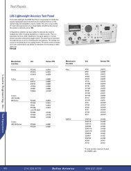
TSC-4100/4200/4300 - Dallas Avionics, Inc.
TSC-4100/4200/4300 - Dallas Avionics, Inc.
TSC-4100/4200/4300 - Dallas Avionics, Inc.

Create successful ePaper yourself
Turn your PDF publications into a flip-book with our unique Google optimized e-Paper software.
SECTION 1<br />
GENERAL DESCRIPTION<br />
1.1 INTRODUCTION<br />
This publication provides general information on the VHF/AM Single Channel Transceivers, Model<br />
TiL-92-SC, Part Nos. 921018-1, 921018-2, and 921018-3 manufactured by Technisonic Industries<br />
Limited. These units are also referred to by Item No.'s <strong>TSC</strong>-<strong>4100</strong>, <strong>TSC</strong>-<strong>4200</strong> and <strong>TSC</strong>-<strong>4300</strong><br />
respectively. This document covers the configuration of this equipment that utilizes either of the<br />
following remote control cards; p/n’s 923051-1 (standard) or 943180-1 (supplied upon request).These<br />
cards allow the transceiver to be remotely controlled over 600 ohm dedicated lines using a variety of<br />
keying methods.<br />
The Model TiL-92-SC Transceivers are simplex, single channel, fixed frequency transceivers<br />
operating over the frequency range of 117.975 MHz to 138.000 MHz. These units are intended for<br />
base station operation in an air traffic environment. These systems can operate from AC power or<br />
external DC power in local and remote operating modes.<br />
1.2 DESCRIPTION<br />
The three rack mounted transceiver configurations are based on the Model 90-6R pre-programmable<br />
transceiver configured for 7 Watt, 15 Watt or 25 Watt operation. All systems can be configured for 2<br />
Wire and 4 Wire remote operation with a variety of remote keying methods (with 923051-1 standard<br />
card). Each configuration consists of a Power Supply Module, Mother Board, and a Remote Control<br />
Board. The 15 Watt and 25 Watt configurations also consist of an RF Amplifier Module.<br />
To improve the rejection of interfering signals, dual conversion receiver technology has been<br />
incorporated on the Transmitter/Receiver (Module A1) board used in Technisonic VHF/AM base<br />
stations. The second IF is 455kHz using a ceramic filter, which is immune to high energy<br />
ringing. The dual conversion module also has a second local oscillator, second mixer and<br />
ceramic filter. The first local oscillator is the original VCO.<br />
The dual conversion receiver board, P/N 003494-1 was implemented into TBS and <strong>TSC</strong> series base<br />
stations starting in January 2001. An option label on the chassis will indicate OPTION 94 if the dual<br />
conversion board is installed. It is possible to retro-fit the dual conversion receiver/transmitter board<br />
into older <strong>TSC</strong>/TBS series base station employing the single conversion board. Please contact<br />
Technisonic for availability of an exchange board.<br />
Note: If a new A1 Module has been retrofitted the squelch circuit must be aligned for the receiver<br />
squelch to operate correctly.<br />
The dual conversion receiver’s squelch knob must be rotated significantly more clockwise (4 o’clock<br />
position) to obtain the same squelch setting (3uV) as a single conversion receiver’s squelch knob set<br />
to the 12 o’clock (straight up) position.<br />
If the dual conversion receiver’s squelch knob is set to the 12 o’clock position, signals with a level<br />
greater than 0.5uV will open the squelch. At most airports this will not be an adequate level of<br />
squelch. Please be aware of this squelch knob adjustment variance when setting and/or<br />
comparing squelch levels of dual conversion vs. single conversion base stations.<br />
An optional RF Crystal Filter which provides higher receiver selectivity is available. These filters can<br />
be ordered to provide either an additional 20dB (4 dB loss sensitivity) or 40dB (7 dB loss) of<br />
selectivity. An RF Isolator which provides unidirectional coupling to the antenna in multiple transmitter<br />
configurations is now standard. Refer to Table 1-1 for system configuration details.<br />
1-1