TSC-4100/4200/4300 - Dallas Avionics, Inc.
TSC-4100/4200/4300 - Dallas Avionics, Inc.
TSC-4100/4200/4300 - Dallas Avionics, Inc.

You also want an ePaper? Increase the reach of your titles
YUMPU automatically turns print PDFs into web optimized ePapers that Google loves.
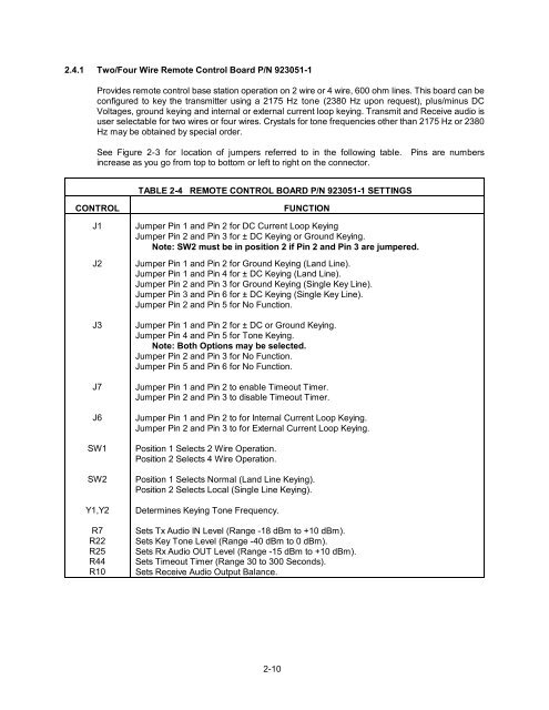
2.4.1 Two/Four Wire Remote Control Board P/N 923051-1<br />
Provides remote control base station operation on 2 wire or 4 wire, 600 ohm lines. This board can be<br />
configured to key the transmitter using a 2175 Hz tone (2380 Hz upon request), plus/minus DC<br />
Voltages, ground keying and internal or external current loop keying. Transmit and Receive audio is<br />
user selectable for two wires or four wires. Crystals for tone frequencies other than 2175 Hz or 2380<br />
Hz may be obtained by special order.<br />
See Figure 2-3 for location of jumpers referred to in the following table. Pins are numbers<br />
increase as you go from top to bottom or left to right on the connector.<br />
TABLE 2-4 REMOTE CONTROL BOARD P/N 923051-1 SETTINGS<br />
CONTROL<br />
J1<br />
J2<br />
J3<br />
J7<br />
J6<br />
SW1<br />
SW2<br />
Y1,Y2<br />
R7<br />
R22<br />
R25<br />
R44<br />
R10<br />
FUNCTION<br />
Jumper Pin 1 and Pin 2 for DC Current Loop Keying<br />
Jumper Pin 2 and Pin 3 for ± DC Keying or Ground Keying.<br />
Note: SW2 must be in position 2 if Pin 2 and Pin 3 are jumpered.<br />
Jumper Pin 1 and Pin 2 for Ground Keying (Land Line).<br />
Jumper Pin 1 and Pin 4 for ± DC Keying (Land Line).<br />
Jumper Pin 2 and Pin 3 for Ground Keying (Single Key Line).<br />
Jumper Pin 3 and Pin 6 for ± DC Keying (Single Key Line).<br />
Jumper Pin 2 and Pin 5 for No Function.<br />
Jumper Pin 1 and Pin 2 for ± DC or Ground Keying.<br />
Jumper Pin 4 and Pin 5 for Tone Keying.<br />
Note: Both Options may be selected.<br />
Jumper Pin 2 and Pin 3 for No Function.<br />
Jumper Pin 5 and Pin 6 for No Function.<br />
Jumper Pin 1 and Pin 2 to enable Timeout Timer.<br />
Jumper Pin 2 and Pin 3 to disable Timeout Timer.<br />
Jumper Pin 1 and Pin 2 to for Internal Current Loop Keying.<br />
Jumper Pin 2 and Pin 3 to for External Current Loop Keying.<br />
Position 1 Selects 2 Wire Operation.<br />
Position 2 Selects 4 Wire Operation.<br />
Position 1 Selects Normal (Land Line Keying).<br />
Position 2 Selects Local (Single Line Keying).<br />
Determines Keying Tone Frequency.<br />
Sets Tx Audio IN Level (Range -18 dBm to +10 dBm).<br />
Sets Key Tone Level (Range -40 dBm to 0 dBm).<br />
Sets Rx Audio OUT Level (Range -15 dBm to +10 dBm).<br />
Sets Timeout Timer (Range 30 to 300 Seconds).<br />
Sets Receive Audio Output Balance.<br />
2-10