AXFE-R114 / AXFE-R1S4 100Base-TX Copper ... - BFi OPTiLAS A/S
AXFE-R114 / AXFE-R1S4 100Base-TX Copper ... - BFi OPTiLAS A/S
AXFE-R114 / AXFE-R1S4 100Base-TX Copper ... - BFi OPTiLAS A/S

Create successful ePaper yourself
Turn your PDF publications into a flip-book with our unique Google optimized e-Paper software.
<strong>AXFE</strong>-<strong>R114</strong> / <strong>AXFE</strong>-<strong>R1S4</strong><br />
<strong>100Base</strong>-<strong>TX</strong> <strong>Copper</strong> SFP Transceiver<br />
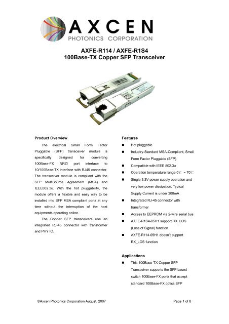
Product Overview<br />
The electrical Small Form Factor<br />
Pluggable (SFP) transceiver module is<br />
specifically designed for converting<br />
<strong>100Base</strong>-FX NRZI port interface to<br />
10/<strong>100Base</strong>-<strong>TX</strong> interface with RJ45 connector.<br />
The transceiver module is compliant with the<br />
SFP MultiSource Agreement (MSA) and<br />
IEEE802.3u. With the hot pluggability, the<br />
module offers a flexible and easy way to be<br />
installed into SFP MSA compliant ports at any<br />
time without the interruption of the host<br />
equipments operating online.<br />
The <strong>Copper</strong> SFP transceivers use an<br />
integrated RJ-45 connector with transformer<br />
and PHY IC.<br />
Features<br />
• Hot pluggable<br />
• Industry-Standard MSA-Compliant, Small<br />
Form Factor Pluggable (SFP)<br />
• Compatible with IEEE 802.3u<br />
• Operation temperature range 0℃ ~ 70℃<br />
• Single 3.3V power supply operation and<br />
very low power dissipation. Typical<br />
Supply Current is under 300mA<br />
• Integrated RJ-45 connector with<br />
transformer<br />
• Access to EEPROM via 2-wire serial bus<br />
• <strong>AXFE</strong>-<strong>R1S4</strong>-05H1 support RX_LOS<br />
(Loss of Signal) function<br />
• <strong>AXFE</strong>-<strong>R114</strong>-05H1 doesn’t support<br />
RX_LOS function<br />
Applications<br />
• This <strong>100Base</strong>-<strong>TX</strong> <strong>Copper</strong> SFP<br />
Transceiver supports the SFP based<br />
switch <strong>100Base</strong>-FX ports that accept<br />
standard <strong>100Base</strong>-FX optics SFP<br />
©Axcen Photonics Corporation August, 2007 Page 1 of 8
Block diagram<br />
<strong>TX</strong>_DATA<br />
RX_DATA<br />
<strong>TX</strong>_DISABLE<br />
<strong>TX</strong>_FAULT<br />
RX_LOS<br />
RATE_SELECT NC<br />
A<br />
PHY IC<br />
B<br />
Magnetics RJ45<br />
Adapter<br />
MOD_DEF0<br />
MOD_DEF1<br />
MOD_DEF2<br />
EEPROM<br />
The transceiver is fundamentally consisted by three parts: RJ45+Magnetics, PHY IC and EEPROM. The<br />
transceiver module can be turned on by setting <strong>TX</strong>_DISABLE = LOW and can be reset by setting<br />
<strong>TX</strong>_DISABLE =High or OPEN. <strong>TX</strong>_FAULT is not supported and always connected to ground. LOS (Loss<br />
of signal) detection is an optional function and please contact Axcen sales representative. For the access<br />
of serial identification information, an EEPROM is used to store the required data via the 2-wire serial<br />
CMOS EEPROM protocol. The detailed signal descriptions are listed in the following sections.<br />
Absolute Maximum Ratings<br />
Parameter Symbol Min. Max. Unit Note<br />
Operating Temperature T OP<br />
0 70 ℃<br />
Storage Temperature T st - 40 85 ℃ 1<br />
Supply Voltage Vcc - 0.5 3.6 V<br />
Supply Current Is 350 mA<br />
Inrush Current I sh 30 mA<br />
Relative Humidity RH 5 95 %<br />
Notes:<br />
1. Ambient Temperature<br />
©Axcen Photonics Corporation August, 2007 Page 2 of 2
Recommended Operating Conditions<br />
Parameter Symbol Min. Typ. Max. Unit Note<br />
Operating Temperature T OP<br />
0 70 ℃ 1<br />
Supply Voltage Vcc 3.15 3.3 3.45 V<br />
Supply Current Is 200 300 mA 2<br />
Notes:<br />
1. Case Temperature,<br />
2. The copper SFP transceiver Meet the requirement of SFP MSA that specifies the maximum current<br />
consumption of 300mA at 3.3V+/ 5%.<br />
High-Speed Electrical Interface, Host to SFP<br />
Parameter Symbol Min. Typ. Max. Unit Note<br />
TD+, TD- Input Voltage Swing Vin+, Vin- 250 1200 mV 2<br />
RD+, RD- Output Voltage Swing Vout+, Vout- 250 800 mV 2<br />
Tx_Disable -High V Disable_H 2 V cc V<br />
Tx_Disable - Low V Disable_L 0 0.4 V<br />
Rise Time (Receiver) t r 2 ns 1<br />
Fall Time (Receiver) t f 2 ns 1<br />
Tx Input Impedance Zin 50 Ohm 2<br />
Rx Output Impedance Zout 50 Ohm 2<br />
Notes:<br />
1. 10% to 90% value<br />
2. Single ended<br />
High-Speed Electrical Interface, Cable to SFP<br />
Parameter Symbol Min. Typ. Max. Unit Note<br />
Transmission Frequency ft 125 MHz 1<br />
Tx Output Impedance Zout.Tx 100 Ohm 2<br />
Rx Output Impedance Zin.Rx 100 Ohm 2<br />
Notes:<br />
1. MLT-3 encoding per IEEE802.3u<br />
2. Differential for frequencies from 1MHz to 125MHz<br />
©Axcen Photonics Corporation August, 2007 Page 3 of 3
General Specifications<br />
Parameter Symbol Min. Typ. Max. Unit Note<br />
Data Rate DR 100 Mb/sec 1<br />
Bit Error Rate BER 10 -10 2<br />
Notes:<br />
1. IEEE802.3u compatible. The host requires an <strong>100Base</strong>-FX NRZI 125Mbps interface with no clock to operated<br />
100 BASE-<strong>TX</strong>.<br />
2. Over 100m Cat 5 UTP Cable<br />
Pin Description<br />
SFP Transceiver Electric Pad Layout<br />
Diagram of Host Board Connector Block<br />
Pin Numbers and Names<br />
Pin No Pin Name Function Plug Seq. Notes<br />
1 VeeT Transmitter Ground 1<br />
2 <strong>TX</strong> Fault Transmitter Fault Indication 3 1<br />
3 <strong>TX</strong> Disable Transmitter Disable 3 2<br />
4 MOD_DEF 2 Module Definition 2 3 3<br />
5 MOD_DEF 1 Module Definition 1 3 3<br />
6 MOD_DEF 0 Module Definition 0 3 3<br />
7 Rate Select Select between full or reduced<br />
3 4<br />
receiver bandwidth<br />
8 LOS Loss of Signal 3 5<br />
9 VeeR Receiver Ground 1 6<br />
10 VeeR Receiver Ground 1 6<br />
11 VeeR Receiver Ground 1 6<br />
©Axcen Photonics Corporation August, 2007 Page 4 of 4
Pin No Pin Name Function Plug Seq. Notes<br />
12 RD - Inv. Received Data Out 3 7<br />
13 RD + Received Data Out 3 7<br />
14 VeeR Receiver Ground 1 6<br />
15 VccR Receiver Power 2 8<br />
16 VccT Transmitter Power 2 8<br />
17 VeeT Transmitter Ground 1 6<br />
18 TD + Transmit Data In 3 9<br />
19 TD - Inv. Transmit Data In 3 9<br />
20 VeeT Transmitter Ground 1 6<br />
Notes:<br />
Plug Seq.: Pin engagement sequence during hot plugging.<br />
1. <strong>TX</strong> Fault is not supported and is always connected to ground.<br />
2. <strong>TX</strong> disable is an input that is used to reset the transceiver module. It is pulled up within the module with a 4.7 – 10<br />
K resistor. Its states are:<br />
Low (0 – 0.8V): transceiver module on<br />
(>0.8, < 2.0V): Undefined<br />
High (2.0 – 3.465V): transceiver module Disabled<br />
Open: transceiver module Disabled<br />
3. Mod-Def 0,1,2. These are the module definition pins. They should be pulled up with a 4.7K - 10K resistor on the<br />
host board. The pull-up voltage shall be VccT or VccR<br />
Mod-Def 0 is grounded in the module to indicate that the module is present<br />
Mod-Def 1 is the clock line of two-wire serial interface for serial ID<br />
Mod-Def 2 is the data line of two-wire serial interface for serial ID<br />
4. Rate select is not required for connection<br />
5. RxLOS (Loss of Signal) : <strong>AXFE</strong>-<strong>R114</strong>-05H1 LOS function is not supported and is always connected to ground.<br />
<strong>AXFE</strong>-<strong>R1S4</strong>-05H1 This active high signal is asserted when the status of network is Link Down. RxLOS is active<br />
low when the status of network is Linkup.<br />
6. VeeR and VeeT may be internally connected within the SFP module.<br />
7. RD-/+: These are the differential receiver outputs. They are AC coupled 100Ω differential lines which should be<br />
terminated with 100 Ω differential at the user SerDes. The AC coupling is done inside the module and is thus not<br />
required on the host board. The voltage swing on these lines will be between 370 and 2000 mV differential (185<br />
mV- 1000 mV single ended) when properly terminated.<br />
8. VccR and VccT are the receiver and transmitter power supplies. They are defined as 3.3V ±5% at the SFP<br />
connector pin. Maximum supply current is 350 mA. Recommended host board power supply filtering is shown<br />
below. Inductors with DC resistance of less than 1 Ω should be used in order to maintain the required voltage at<br />
the SFP input pin with 3.3V supply voltage. When the recommended supply filtering network is used, hot plugging<br />
of the SFP transceiver module will result in an inrush current of no more than 30 mA greater than the steady state<br />
value. VccR and VccT may be internally connected within the SFP transceiver module.<br />
9. TD-/+: These are the differential transmitter inputs. They are AC-coupled differential lines with 100Ω differential<br />
termination inside the module. The AC coupling is done inside the module and is thus not required on the host<br />
board. The inputs will accept differential swings of 500 – 2400mV (250 mV - 1200 mV single ended), though it is<br />
recommended that values between 500 and 1200mV differential (250 – 600mV single ended) be used for best<br />
EMI performance.<br />
©Axcen Photonics Corporation August, 2007 Page 5 of 5
Recommended Host Board Supply Filtering Network<br />
SFP Host Board Schematic<br />
©Axcen Photonics Corporation August, 2007 Page 6 of 6
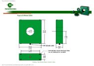
Mechanical Dimensions (Units in mm)<br />
©Axcen Photonics Corporation August, 2007 Page 7 of 7
Ordering Information<br />
Product Code<br />
<strong>AXFE</strong>-<strong>R114</strong>-05H1<br />
<strong>AXFE</strong>-<strong>R1S4</strong>-05H1<br />
Description<br />
<strong>100Base</strong>-<strong>TX</strong> <strong>Copper</strong> SFP, 3.3V, 0~70℃, without LOS function<br />
<strong>100Base</strong>-<strong>TX</strong> <strong>Copper</strong> SFP, 3.3V, 0~70℃, with LOS function<br />
©Axcen Photonics Corporation August, 2007 Page 8 of 8