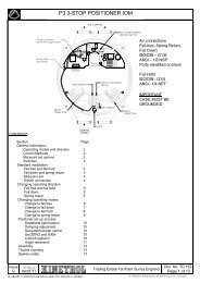
Installation - Kinetrol
Installation - Kinetrol
Installation - Kinetrol

Create successful ePaper yourself
Turn your PDF publications into a flip-book with our unique Google optimized e-Paper software.
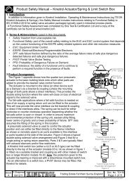
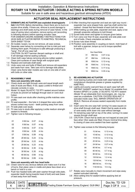
<strong>Installation</strong>, Operation & Maintenance Instructions<br />
ROTARY 1/4 TURN ACTUATOR / DOUBLE ACTING & SPRING RETURN MODELS<br />
Suitable for use in safe area and hazardous gas/dust atmospheres (ATEX)<br />
ACTUATOR SEAL REPLACEMENT INSTRUCTIONS<br />
1. DISMANTLING ACTUATOR (see exploded drawing/parts<br />
list) CAUTION: Before dismantling, check there are no burrs on<br />
square drive shafts. If there are, remove to avoid damage to<br />
bearings and shaft seals during removal of case halves. In the<br />
case of spring return actuators, remove spring unit (according<br />
to following section) before opening actuator case.<br />
FOR DISMANTLING/RE-ASSEMBLY INSTRUCTIONS FOR<br />
20/30 SIZE ACTUATOR REFER TO KINETROL TECHNICAL<br />
DATA SHEET TD104.<br />
2.10 After checking that expander and seal are right way round -<br />
expander has vane shaped hole, seal has shaft centre line<br />
marked - thread first few threads of each bolt into vane.<br />
2.11 While holding up side plate, expander and seal, apply a low<br />
strength anaerobic adhesive to bolt thread.<br />
2.12 Screw bolts down and tighten to torques given below.<br />
2.13 Turn vane over then fit seal, expander and side plate over<br />
end of bolts. Check orientation as before.<br />
2.14 Screw nuts down thread.<br />
1.1 All models: loosen, but do not remove, all case screws.<br />
1.2 Separate case halves by connecting air line to inlet port and<br />
blowing them apart. Procedure is safe although producing a<br />
2.15 Position vane assembly in coupling on bench, hold head of<br />
bolt with a spanner, torque up nut to torque specified<br />
in section 2.7.<br />
“bang”. Pull off one case half.<br />
Hex Head Bolts<br />
CAUTION: Do NOT hammer diecast castings or shaft end.<br />
It will damage internal sealing surfaces.<br />
01 6lbf./ins 0.07 m kg<br />
1.3 Clean both case halves removing silicone rubber sealant.<br />
07 8lbf./ins 0.09 m kg<br />
Clean joint surfaces of case flange with surgical spirit.<br />
08 10lbf./ins 0.12 m kg<br />
1.4 Replace and lubricate shaft seals.<br />
1.5 Undo vane nuts and bolts (if fitted) and remove old expanders<br />
09 10lbf./ins 0.12 m kg<br />
and seals from vane. Take care not to damage side plates.<br />
Clean vane.Some later models use nuts on one side of vane<br />
with bolts on other side.<br />
10<br />
12<br />
15lbf./ins<br />
30lbf./ins<br />
0.17 m kg<br />
0.35 m kg<br />
2. REASSEMBLY VANE<br />
Vane sub assembly with studs<br />
2.1 Check studs are tight through vane and equal length each<br />
side (if studs are fitted). If not, apply Loctite to thread and<br />
relocate correctly in vane.<br />
2.2 Model 18: Apply SILASTIC 732 RTV sealant around bottom<br />
of studs (to prevent air leakage through seal on vane stud<br />
holes).<br />
2.3 Fit new seal over studs after checking profile matches vane<br />
profile.<br />
2.4 Fit seal expander – the hole in it shaped like vane outline<br />
shows correct way round – teeth pointing away from vane.<br />
2.5 Fit side plate over studs.<br />
2.6 Fit new nuts to studs after applying Loctite medium strength<br />
sealant to threads.<br />
2.7 Tighten nuts to following torques:<br />
01 6 lbf.ins 0.07 m kg<br />
02 6 lbf.ins 0.07 m kg<br />
03 6 lbf.ins 0.07 m kg<br />
05 8 lbf.ins 0.09 m kg<br />
07 8 lbf.ins 0.09 m kg<br />
08 20 lbf.ins 0.23 m kg<br />
09 20 lbf.ins 0.23 m kg<br />
10 20 lbf.ins 0.23 m kg<br />
12 30 lbf.ins 0.35 m kg<br />
14 30 lbf.ins 0.35 m kg<br />
16 60 lbf.ins 0.69 m kg<br />
18 60 lbf.ins 0.69 m kg<br />
Vane sub assembly with hex head bolts<br />
2.8 Check vane for any obvious defects and make sure it is free<br />
of burrs, then place vane in cradle and place face down an a<br />
bench or hold in a vice.<br />
2.9 Push hex headed bolts with plain washer through side plate,<br />
expander (teeth facing towards head of bolt) and seal (base<br />
of seal away from bolt head).<br />
ISSUE<br />
K<br />
3. RE-ASSEMBLING ACTUATOR<br />
3.1 Coat bearing bushes and inside both case halves with<br />
molybdenum disulphide grease or grease supplied by<br />
KINETROL.<br />
3.2 Lightly and evenly coat joint face on each case half with<br />
INSTANT GASKET sealant (up to Model 14) available from<br />
<strong>Kinetrol</strong> (SP057) or Loctite, or SILASTIC 732 RTV sealant<br />
(Model 16 up) obtainable from ironmongers, etc. may be<br />
used as a substitute. CAUTION: EXCESS SEALANT, if<br />
extruded inside case, WILL IMPAIR OPERATION OF<br />
SEALS. Remove all excess sealant especially from inside<br />
edge.<br />
3.3 Insert vane into one case half, turning it to ease square on<br />
drive shaft through shaft seal. Watch that lip seals at ends<br />
of vane easily work down into case without damage.<br />
3.4 Fit remaining case half on top of the other, turning it to ease<br />
square through shaft seal.<br />
3.5 CAUTION: Check that lip seals are not trapped at case joint<br />
face when Viton seals are fitted. Ensure minimal time delay<br />
to closing of case once sealant has been applied<br />
3.6 Tighten case screws to the following torques:<br />
01 10 lbf.ins. 0.12 m kg<br />
02 10 lbf.ins. 0.12 m kg<br />
03 10 lbf.ins. 0.12 m kg<br />
05 20 lbf.ins. 0.23 m kg<br />
07 24 lbf.ins. 0.27 m kg<br />
08 60 lbf.ins. 0.7 m kg<br />
09 60 lbf.ins. 0.7 m kg<br />
10 80 lbf.ins. 0.9 m kg<br />
12 100 lbf.ins. 1.2 m kg<br />
14 120 lbf.ins. 1.4 m kg<br />
16 860 lbf.ins. 10 m kg<br />
18 1140 lbf.ins. 13 m kg<br />
3.7 Rotate vane manually to check movement and wipe away<br />
sealant extruded internally.<br />
3.8 Allow setting time for sealant before applying test air<br />
pressure.<br />
DATE<br />
08/12 Trading Estate Farnham Surrey England. GU9 9NU<br />
AR 5474 / ISS.J - AR 4777 / ISS.H - AR 4726<br />
Doc.No. TD 129<br />
Page 3 OF 8 KF464