Installation - Kinetrol
Installation - Kinetrol
Installation - Kinetrol

Create successful ePaper yourself
Turn your PDF publications into a flip-book with our unique Google optimized e-Paper software.
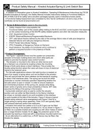
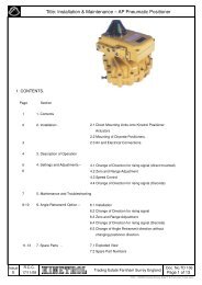
<strong>Installation</strong>, Operation & Maintenance Instructions<br />
ROTARY 1/4 TURN ACTUATOR / DOUBLE ACTING & SPRING RETURN MODELS<br />
Suitable for use in safe area and hazardous gas/dust atmospheres (ATEX)<br />
Conversely if actual pressure at 3.2.4 is significantly greater<br />
than half operating pressure then spring tension is above the<br />
optimum, i.e. S/R torque will be greater than air stroke torque.<br />
3.3 Tension Adjustment Method (Standard S/R units without<br />
worm drive)<br />
3.3.1 Equipment/facilities required:<br />
Air supply with pressure regulator valve and gauge in line.<br />
Keeper plate with bolts and spacers (KINETROL supply).<br />
Spanner/tools to suit.<br />
Means of securely fixing assembly to a suitable work bench.<br />
3.3.2 Detach actuator/spring return from valve/mechanism.<br />
3.3.3 Connect air supply to actuator with regulator shut off.<br />
3.3.4 Carry out optimum spring setting test as at 2.2 above to<br />
determine whether spring tension needs to be increased or<br />
decreased.<br />
3.3.5 Gradually open air supply regulator until actuator vane<br />
is at centre of travel (45°) position (see sketch at page 1).<br />
3.3.6 Place keeper plate over S/R square shaft at top of S/R<br />
unit.<br />
CAUTION: If keeper plate of flat type, spacer washers at<br />
least 3mm (1/8") thick must be used under keeper plate.<br />
KINETROL die cast keeper plates do not need spacer<br />
washers.<br />
3.3.7 If bolt holes of keeper plate do not line up with<br />
corresponding tapped holes in S/R unit, carefully open or<br />
close air supply regulator until S/R square shaft turns so that<br />
holes do line up.<br />
3.3.8 Insert and tighten keeper plate bolts.<br />
3.3.9 Shut off air supply to actuator.<br />
3.3.10 Undo and remove all spring housing flange bolts.<br />
Leave spring housing resting on base plate.<br />
3.3.11 Turn spring housing in required direction according to:<br />
a) S/R operating direction, i.e. clockwise or<br />
anticlockwise operation of spring force, and<br />
b) Tension required to be increased or<br />
decreased.<br />
NOTE: Larger sizes of actuator/spring return will require<br />
spanner and possibly extension bar to turn spring housing<br />
through square shaft on S/R unit.<br />
3.3.12 Dependent on the age of S/R unit concerned there will<br />
be 12 or 24 bolt holes around the base plate flange (except<br />
for 014 and 08 models which have only 4, and 144 model which<br />
now has 36).<br />
Therefore older models (12 holes) can only be adjusted by<br />
30° steps, whereas new models can be adjusted by 15° steps<br />
(014 and 08 by 90° steps and current 144 by 10° steps).<br />
3.3.13 As a rough guide 30° adjustment of spring housing<br />
relative to base plate will give 8% change of spring torque<br />
output providing spring is already tensioned within its<br />
operating air pressure range, i.e. standard S/R units between<br />
50 and 80 p.s.i. Low air supply S/R units between 25 and 50<br />
p.s.i. See catalogue for full details.<br />
3.3.14 Maximum adjustment in one step will be 45° controlled<br />
by available vane movement in actuator.<br />
3.3.15 After turning spring housing by amount required (or<br />
possible) line up bolt holes in spring housing and base plate<br />
flanges. Insert flange bolts and tighten nuts.<br />
3.3.16 Carefully open air supply to actuator until side load on<br />
keeper plate bolts is relieved.<br />
3.3.17 Remove keeper plate.<br />
3.3.18 Repeat optimum spring setting test as at 4.2 above.<br />
3.3.19 If necessary, repeat operations 4.3.5 to 4.3.17 to<br />
further increase or decrease spring tension.<br />
WARNING: Spring tension must not be further increased if<br />
air pressure noted at 4.2.4 is 40 p.s.i. or more for standard<br />
S/R units or 30 p.s.i. for special low air supply types.<br />
Note: If alignment of mounting holes to square is important,<br />
then the spring tension should only be moved in 90°<br />
increments. This is especially important with female drive<br />
spring units where the mounting angle to the valve will<br />
determine correct opening/closing of valve.<br />
4. LABELLING (ATEX)<br />
All spring units that are suitable for use in explosive areas<br />
are labelled with one of the labels as shown in 8 in actuator<br />
section above.<br />
Ensure that the details on the label such as the ambient<br />
temperature range is suitable for the application.<br />
Also ensure that any other equipment fitted to the spring<br />
return (e.g. limit switch box or positioner) does not restrict<br />
the use within the parameters shown on the above labels.<br />
Certificate of Conformance, TD125, shows the category of<br />
spring return approval for different sizes of spring units.<br />
5. SPARE PART ORDER CODES – KEEPER PLATES:<br />
SPRING<br />
SIZE<br />
MALE DRIVE FEMALE ISO<br />
DRIVE<br />
FEMALE SERRATED<br />
DRIVE<br />
01 SP 350 N/A N/A<br />
02 SP 351 N/A N/A<br />
03 SP 352 SP 1360/1 N/A<br />
05 SP 353 SP 1362/3 SP 1480<br />
07 SP 354 SP 1364 SP 1481<br />
08 SP 904 SP 1378 SP 1483<br />
09 SP 356 SP 1365 SP 1482<br />
10 SP 359 SP 1366 SP 1482<br />
12 SP 357 SP 1368 SP 1370 N/A<br />
14 SP 358 SP 1371 N/A<br />
16 SP 360 SP 1372 N/A<br />
18 SP 361 SP 1373 N/A<br />
20 SP 362 SP 1374 N/A<br />
30 SP 362 N/A N/A<br />
For non-standard spring codes please contact <strong>Kinetrol</strong>.<br />
ISSUE<br />
K<br />
DATE<br />
08/12 Trading Estate Farnham Surrey England. GU9 9NU<br />
AR 5474 / ISS.J - AR 4777 / ISS.H - AR 4726<br />
Doc.No. TD 129<br />
Page 5 OF 8 KF464