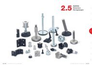
Tube clamp connectors Linear actuators - Ganter Griff
Tube clamp connectors Linear actuators - Ganter Griff
Tube clamp connectors Linear actuators - Ganter Griff

You also want an ePaper? Increase the reach of your titles
YUMPU automatically turns print PDFs into web optimized ePapers that Google loves.
<strong>Tube</strong> <strong>clamp</strong> <strong>connectors</strong><br />
<strong>Linear</strong> <strong>actuators</strong>
<strong>Tube</strong> <strong>clamp</strong> <strong>connectors</strong> / <strong>Linear</strong> <strong>actuators</strong><br />
Otto <strong>Ganter</strong> GmbH & Co. KG<br />
Triberger Straße 3<br />
D-78120 Furtwangen<br />
Germany<br />
Phone<br />
Fax<br />
E-Mail<br />
Internet<br />
+49 77 23 65 07-0<br />
+49 77 23 46 59<br />
info@ganter-griff.de<br />
www.ganter-griff.com<br />
1
2<br />
GN 131<br />
Two-way<br />
connector<br />
<strong>clamp</strong>s<br />
Aluminium<br />
Page 10<br />
GN 132<br />
Two-way<br />
connector<br />
<strong>clamp</strong>s<br />
Aluminium<br />
Page 12<br />
GN 133<br />
Two-way<br />
connector<br />
<strong>clamp</strong>s<br />
Aluminium<br />
Page 13<br />
GN 134<br />
Two-way<br />
connector<br />
<strong>clamp</strong>s<br />
Aluminium<br />
Page 14<br />
GN 141<br />
Flanged<br />
two-way<br />
connector<br />
<strong>clamp</strong>s<br />
Aluminium<br />
Page 15<br />
<strong>Tube</strong> <strong>clamp</strong> <strong>connectors</strong><br />
<strong>Linear</strong> <strong>actuators</strong><br />
GN 131<br />
Two-way<br />
connector<br />
<strong>clamp</strong>s<br />
Stainless Steel<br />
Page 10<br />
GN 145<br />
Flanged<br />
connector<br />
<strong>clamp</strong>s<br />
Aluminium<br />
Page 16<br />
GN 145<br />
Flanged<br />
connector<br />
<strong>clamp</strong>s<br />
Stainless Steel<br />
Page 16<br />
GN 146<br />
Flanged<br />
connector<br />
<strong>clamp</strong>s<br />
Aluminium<br />
Page 18<br />
GN 146.3<br />
Flanged<br />
connector<br />
<strong>clamp</strong>s<br />
Aluminium<br />
Page 19<br />
GN 147<br />
Flanged<br />
connector<br />
<strong>clamp</strong>s<br />
Aluminium<br />
Page 20<br />
GN 162<br />
Base plate<br />
connector<br />
<strong>clamp</strong>s<br />
Aluminium<br />
Page 21<br />
GN 162<br />
Base plate<br />
connector<br />
<strong>clamp</strong>s<br />
Stainless Steel<br />
Page 21<br />
GN 163<br />
Base plate<br />
connector<br />
<strong>clamp</strong>s<br />
Aluminium<br />
Page 23<br />
Stainless Steel<br />
GN 165<br />
Base plate<br />
connector<br />
<strong>clamp</strong>s<br />
Aluminium<br />
Page 24<br />
GN 166<br />
Off-set<br />
base plate<br />
connector<br />
<strong>clamp</strong>s<br />
Aluminium<br />
Page 25<br />
GN 167<br />
Wide base plate<br />
connector<br />
<strong>clamp</strong>s<br />
Aluminium<br />
Page 26<br />
GN 171<br />
Flanged<br />
base plate<br />
connector<br />
<strong>clamp</strong>s<br />
Aluminium<br />
Page 27<br />
GN 191<br />
T-Angle<br />
connector<br />
<strong>clamp</strong>s<br />
Aluminium<br />
Page 28<br />
GN 191<br />
T-Angle<br />
connector<br />
<strong>clamp</strong>s<br />
Stainless Steel<br />
Page 28<br />
GN 192<br />
T-Angle<br />
connector<br />
<strong>clamp</strong>s<br />
Aluminium<br />
Page 30
GN 193<br />
T-Angle<br />
connector<br />
<strong>clamp</strong>s<br />
Aluminium<br />
Page 31<br />
GN 194<br />
T-Angle<br />
connector<br />
<strong>clamp</strong>s<br />
Aluminium<br />
Page 32<br />
GN 195<br />
T-Angle<br />
connector<br />
<strong>clamp</strong>s<br />
Aluminium<br />
Page 33<br />
GN 231<br />
<strong>Tube</strong><br />
supports<br />
Aluminium<br />
Page 34<br />
GN 241<br />
<strong>Tube</strong><br />
<strong>connectors</strong><br />
Aluminium<br />
Page 35<br />
GN 242<br />
<strong>Tube</strong><br />
<strong>connectors</strong><br />
Aluminium<br />
Page 36<br />
<strong>Tube</strong> <strong>clamp</strong> <strong>connectors</strong><br />
<strong>Linear</strong> <strong>actuators</strong><br />
GN 271<br />
Swivel <strong>clamp</strong><br />
connector<br />
bases<br />
Aluminium<br />
Page 38<br />
GN 272<br />
Swivel <strong>clamp</strong><br />
connector<br />
bases<br />
Aluminium<br />
Page 39<br />
GN 273<br />
Swivel <strong>clamp</strong><br />
<strong>connectors</strong><br />
Aluminium<br />
Page 40<br />
GN 274<br />
Swivel <strong>clamp</strong><br />
<strong>connectors</strong><br />
Aluminium<br />
Page 41<br />
GN 275<br />
Swivel <strong>clamp</strong><br />
<strong>connectors</strong><br />
Aluminium<br />
Page 42<br />
GN 276<br />
Swivel <strong>clamp</strong><br />
<strong>connectors</strong><br />
Aluminium<br />
Page 43<br />
GN 277<br />
Swivel <strong>clamp</strong><br />
<strong>connectors</strong><br />
Aluminium<br />
Page 44<br />
GN 278<br />
Swivel <strong>clamp</strong><br />
<strong>connectors</strong><br />
Aluminium<br />
Page 45<br />
Stainless Steel<br />
GN 281<br />
Swivel <strong>clamp</strong><br />
connector<br />
joints<br />
Aluminium<br />
Page 48<br />
GN 282<br />
Swivel <strong>clamp</strong><br />
connector<br />
joints<br />
Aluminium<br />
Page 49<br />
GN 283<br />
Swivel <strong>clamp</strong><br />
connector<br />
joints<br />
Aluminium<br />
Page 50<br />
GN 284<br />
Swivel <strong>clamp</strong><br />
connector<br />
joints<br />
Aluminium<br />
Page 51<br />
GN 285<br />
Swivel <strong>clamp</strong><br />
connector<br />
joints<br />
Aluminium<br />
Page 52<br />
GN 286<br />
Swivel <strong>clamp</strong><br />
connector<br />
joints<br />
Aluminium<br />
Page 53<br />
GN 287<br />
Swivel <strong>clamp</strong><br />
connector<br />
joints<br />
Aluminium<br />
Page 54<br />
3
4<br />
<strong>Tube</strong> <strong>clamp</strong> <strong>connectors</strong><br />
<strong>Linear</strong> <strong>actuators</strong><br />
GN 288<br />
Swivel <strong>clamp</strong><br />
connector<br />
joints<br />
Aluminium<br />
Page 55<br />
GN 271.4<br />
Sensor holders<br />
Aluminium<br />
Page 56<br />
GN 272.4<br />
Sensor holders<br />
Aluminium<br />
Page 57<br />
GN 273.4<br />
Sensor holders<br />
Aluminium<br />
Page 58<br />
GN 990<br />
Construction<br />
tubings<br />
Steel, Aluminium<br />
Page 59<br />
GN 990<br />
Construction<br />
tubings<br />
Stainless Steel<br />
Page 59<br />
GN 991<br />
<strong>Tube</strong> end plugs<br />
Technopolymer<br />
Page 60<br />
GN 992<br />
Insert bushes<br />
Aluminium<br />
Page 61<br />
GN 911<br />
Clamping<br />
kits<br />
Stainless Steel<br />
Page 63<br />
GN 291<br />
<strong>Linear</strong><br />
<strong>actuators</strong><br />
Steel,<br />
Stainless Steel<br />
Page 68<br />
GN 292<br />
<strong>Linear</strong><br />
<strong>actuators</strong><br />
Steel,<br />
Stainless Steel<br />
Page 70<br />
GN 293<br />
<strong>Linear</strong><br />
<strong>actuators</strong><br />
Steel,<br />
Stainless Steel<br />
Page 71<br />
GN 131.1<br />
<strong>Linear</strong><br />
actuator<br />
<strong>connectors</strong><br />
Aluminium<br />
Page 72<br />
GN 131.1<br />
<strong>Linear</strong><br />
actuator<br />
<strong>connectors</strong><br />
Stainless Steel<br />
Page 72<br />
Stainless Steel<br />
GN 131.2<br />
<strong>Linear</strong><br />
actuator<br />
<strong>connectors</strong><br />
Aluminium<br />
Page 72<br />
GN 131.2<br />
<strong>Linear</strong><br />
actuator<br />
<strong>connectors</strong><br />
Stainless Steel<br />
Page 72<br />
GN 132.1<br />
<strong>Linear</strong> actuator<br />
<strong>connectors</strong><br />
Aluminium<br />
Page 73<br />
GN 132.2<br />
<strong>Linear</strong> actuator<br />
<strong>connectors</strong><br />
Aluminium<br />
Page 73<br />
GN 145.1<br />
Flanged<br />
linear actuator<br />
<strong>connectors</strong><br />
Aluminium<br />
Page 74<br />
GN 145.1<br />
Flanged<br />
linear actuator<br />
<strong>connectors</strong><br />
Stainless Steel<br />
Page 74<br />
GN 146.1<br />
Flanged<br />
linear actuator<br />
<strong>connectors</strong><br />
Aluminium<br />
Page 75
<strong>Tube</strong> <strong>clamp</strong> <strong>connectors</strong><br />
<strong>Linear</strong> <strong>actuators</strong><br />
GN 162.1<br />
Base plate<br />
linear actuator<br />
<strong>connectors</strong><br />
Aluminium<br />
Page 76<br />
GN 162.1<br />
Base plate<br />
linear actuator<br />
<strong>connectors</strong><br />
Stainless Steel<br />
Page 76<br />
GN 163.1<br />
Base plate<br />
linear actuator<br />
<strong>connectors</strong><br />
Aluminium<br />
Page 77<br />
GN 191.1<br />
T-Angle<br />
linear actuator<br />
<strong>connectors</strong><br />
Aluminium<br />
Page 78<br />
GN 191.1<br />
T-Angle<br />
linear actuator<br />
<strong>connectors</strong><br />
Stainless Steel<br />
Page 78<br />
GN 192.1<br />
T-Angle<br />
linear actuator<br />
<strong>connectors</strong><br />
Aluminium<br />
Page 79<br />
GN 273.1<br />
Swivel <strong>clamp</strong><br />
linear actuator<br />
<strong>connectors</strong><br />
Aluminium<br />
Page 80<br />
GN 274.1<br />
Swivel <strong>clamp</strong><br />
linear actuator<br />
<strong>connectors</strong><br />
Aluminium<br />
Page 81<br />
GN 291.1<br />
Square<br />
linear <strong>actuators</strong><br />
Steel<br />
Page 82<br />
GN 147.1<br />
Flanged<br />
linear actuator<br />
<strong>connectors</strong><br />
Aluminium<br />
Page 84<br />
GN 134.1<br />
Two-way<br />
linear actuator<br />
<strong>connectors</strong><br />
Aluminium<br />
Page 85<br />
GN 165.1<br />
Base plate<br />
linear actuator<br />
<strong>connectors</strong><br />
Aluminium<br />
Page 86<br />
GN 923.18<br />
Handwheel for<br />
linear actuator<br />
Ø 18<br />
Page 88<br />
GN 923.30<br />
GN 923.40<br />
Handwheels for<br />
linear actuator<br />
Ø 30 and 30<br />
Ø 40 and 40<br />
Page 88<br />
Stainless Steel<br />
GN 924.40<br />
GN 924.50<br />
Handwheels for<br />
linear actuator<br />
Ø 40 and 40<br />
Ø 50 and 50<br />
Page 89<br />
GN 924.60<br />
Handwheel for<br />
linear actuator<br />
Ø 60<br />
Page 89<br />
GN 295<br />
Installation kits<br />
for position<br />
indicators used<br />
on linear<br />
<strong>actuators</strong><br />
Page 90<br />
GN 299<br />
Longitudinal<br />
scales for<br />
linear <strong>actuators</strong><br />
Page 92 / 93<br />
GN 391<br />
Transfer<br />
units<br />
Steel,<br />
Stainless Steel<br />
Page 94<br />
GN 297<br />
Bevel-gear<br />
wheels for<br />
transfer units<br />
Steel<br />
Page 95<br />
GN 298<br />
Housings<br />
for angular /<br />
T-gears<br />
Aluminium<br />
Page 96 / 97<br />
5
6<br />
<strong>Tube</strong> <strong>clamp</strong> <strong>connectors</strong> / <strong>Linear</strong> <strong>actuators</strong><br />
<strong>Tube</strong> <strong>clamp</strong> <strong>connectors</strong> are <strong>clamp</strong>ing components which offer the facility<br />
for simply and rapidly constructing jigs, fixtures and operating systems<br />
using standard round and square section tubings.<br />
The vast range of <strong>clamp</strong> <strong>connectors</strong> in split monoblock or multi-part form<br />
offer almost unlimited possibilities.<br />
Split monoblock <strong>clamp</strong> <strong>connectors</strong> give very robust and sturdy tubular<br />
constructions. For this purpose only precision tubings DIN 2391, with an<br />
outside diameter which lies within relatively tight tolerances, should be<br />
used (construction tubings GN 990).<br />
Multi-part <strong>clamp</strong> <strong>connectors</strong> (consisting of two or more separate parts) are<br />
not tied to tight tolerances as they can also be used with square section<br />
tubings thus allowing incorporation into already existing systems.<br />
As <strong>clamp</strong>ing screws there is a choice of either cap head screws to DIN 912<br />
or adjustable <strong>clamp</strong>ing kits GN 911 if repeated removal and re-installation<br />
is required. As for nuts, hexagon nuts DIN 985 (ISO 10511) which are selflocking<br />
with polyamide ring are recommended.<br />
The <strong>clamp</strong>ing points are provided on both sides with sockets, cast in the<br />
component, which give a free choice for positioning hexagon nuts and<br />
<strong>clamp</strong>ing <strong>connectors</strong>.<br />
<strong>Linear</strong> <strong>actuators</strong> consist of a guide tube, a threaded internal spindle i.e.<br />
lead screw and a follower nut.<br />
Within the tube <strong>clamp</strong> <strong>connectors</strong> range there are numerous <strong>clamp</strong>ing<br />
components available to mount the linear <strong>actuators</strong> in a static position<br />
for the linear actuator <strong>connectors</strong> to perform operations which require<br />
a linear movement. <strong>Linear</strong> <strong>actuators</strong> are designed for manual operation<br />
(handwheels).<br />
Further details about tube <strong>clamp</strong> <strong>connectors</strong> and linear <strong>actuators</strong> are given<br />
on the separate standards sheets.<br />
Two-way<br />
connector <strong>clamp</strong>s<br />
Page 10<br />
Flanged two-way<br />
connector <strong>clamp</strong>s<br />
Page 15<br />
Flanged<br />
connector <strong>clamp</strong>s<br />
Page 16<br />
Base plate<br />
connector <strong>clamp</strong>s<br />
Page 21<br />
Flanged base plate<br />
connector <strong>clamp</strong>s<br />
Page 27<br />
T-angle<br />
connector <strong>clamp</strong>s<br />
Page 28<br />
<strong>Tube</strong> <strong>connectors</strong><br />
Page 35<br />
Swivel<br />
<strong>clamp</strong> <strong>connectors</strong><br />
Page 38<br />
Swivel <strong>clamp</strong><br />
connector joints<br />
Page 48<br />
Sensor holders<br />
Page 56<br />
<strong>Linear</strong> <strong>actuators</strong><br />
Page 66 / 82
Design shapes<br />
<strong>Tube</strong> <strong>clamp</strong> <strong>connectors</strong> / <strong>Linear</strong> <strong>actuators</strong><br />
7
8<br />
GN 147<br />
GN 291<br />
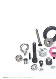
Mobile lifting table<br />
Installation examples<br />
<strong>Tube</strong> <strong>clamp</strong> <strong>connectors</strong><br />
GN 146.1<br />
GN 132<br />
GN 193
Installation examples<br />
<strong>Tube</strong> <strong>clamp</strong> <strong>connectors</strong><br />
9
d1<br />
Bore B<br />
Aluminium<br />
10<br />
St. Steel<br />
Two-way connector <strong>clamp</strong>s<br />
d2<br />
Bore B<br />
Aluminium<br />
St. Steel<br />
k<br />
Clamping<br />
length<br />
d3<br />
Clamping<br />
thread<br />
Length l m Clamping lever<br />
for d3<br />
B 10 - B 10 - 25 M 6 64 20 GN 911-M6-22<br />
B 12 B 12 B 12 B 12 25 M 6 64 20 GN 911-M6-22<br />
B 14 B 14 B 14 B 14 25 M 6 64 20 GN 911-M6-22<br />
B 15 - B 15 - 25 M 6 64 20 GN 911-M6-22<br />
B 16 B 16 B 16 B 16 25 M 6 64 20 GN 911-M6-22<br />
B 18 B 18 B 18 B 18 25 M 6 64 20 GN 911-M6-22<br />
- B 20 - B 20 25 M 6 64 20 GN 911-M6-22<br />
Specification Information How to order<br />
� Aluminium<br />
plastic coated<br />
black SW RAL 9005<br />
textured finish<br />
blank BL<br />
matt shot-blasted<br />
� Stainless Steel NI<br />
German Material No. 1.4308<br />
matt polished<br />
� Clamping bores machined<br />
The <strong>clamp</strong>ing bores of the two-way connector<br />
<strong>clamp</strong>s GN 131 (photo page 11) are machined<br />
and designed for construction tubings GN 990 or<br />
DIN 2391, DIN 2395 and DIN 2462 respectively.<br />
The standard <strong>clamp</strong>ing bolts are socket cap<br />
screws DIN 912. They can be replaced by adjustable<br />
<strong>clamp</strong>ing levers GN 911 (see table of dimensions).<br />
Special executions:<br />
different combinations of bores d1 / d2<br />
Construction tubings GN 990 page 59<br />
<strong>Linear</strong> actuator <strong>connectors</strong> GN 131.1 / GN 131.2<br />
(for linear <strong>actuators</strong>) page 72<br />
Aluminium<br />
Stainless Steel<br />
Two-way connector <strong>clamp</strong><br />
GN 131-B14-B14-1 -BL<br />
| | | | |<br />
Code No.<br />
d1<br />
d2<br />
Id. No.<br />
Finish<br />
Stainless Steel-<br />
Two-way connector <strong>clamp</strong><br />
GN 131-B18-B18-2 -NI<br />
| | | | |<br />
Code No.<br />
d1<br />
GN 131<br />
Id. No. 1 with 2 <strong>clamp</strong>ing screws DIN 912, zinc plated Id. No. 2 with 2 Stainless Steel-<strong>clamp</strong>ing screws DIN 912<br />
� Socket cap screws DIN 912<br />
Steel zinc plated / St. Steel<br />
German Material No. 1.4301<br />
� Hexagon nuts DIN 985<br />
Steel zinc plated / St. Steel<br />
German Material No. 1.4301<br />
� Adjustable<br />
<strong>clamp</strong>ing lever GN 911<br />
Inserts / Distance bushings<br />
Stainless Steel<br />
German Material No. 1.4305<br />
d2<br />
Id. No.<br />
Finish<br />
Adjustable <strong>clamp</strong>ing levers<br />
GN 911 have to be ordered<br />
separately. They are<br />
supplied disassembled.
Two-way connector <strong>clamp</strong>s GN 131 p. 10<br />
Stainless Steel-Two-way connector <strong>clamp</strong>s GN 131 p. 10<br />
Two-way connector <strong>clamp</strong>s GN 132 p. 12<br />
Two-way connector <strong>clamp</strong>s GN 133 p. 13<br />
Two-way connector <strong>clamp</strong>s GN 134 p. 14<br />
Flanged two-way connector <strong>clamp</strong>s GN 141 p. 15<br />
11
d1<br />
Bore B<br />
12<br />
d2<br />
Bore B<br />
Two-way connector <strong>clamp</strong>s<br />
k<br />
Clamping<br />
length<br />
d3<br />
Clamping<br />
thread<br />
l1 l2 m Clamping lever<br />
for d3<br />
B 20 B 20 40 M 8 97 40 33 GN 911-M 8-32<br />
B 25 B 25 40 M 8 97 40 33 GN 911-M 8-32<br />
B 30 B 30 40 M 8 97 40 33 GN 911-M 8-32<br />
B 30 B 30 56 M 10 125 56 45 GN 911-M10-40<br />
B 32 B 32 56 M 10 125 56 45 GN 911-M10-40<br />
B 35 B 35 56 M 10 125 56 45 GN 911-M10-40<br />
B 40 B 40 56 M 10 125 56 45 GN 911-M10-40<br />
B 40 B 40 65 M 10 143 65 53 GN 911-M10-55<br />
B 42 B 42 65 M 10 143 65 53 GN 911-M10-55<br />
B 45 B 45 65 M 10 143 65 53 GN 911-M10-55<br />
B 48 B 48 65 M 10 143 65 53 GN 911-M10-55<br />
B 50 B 50 65 M 10 143 65 53 GN 911-M10-55<br />
B 50 B 50 80 M 10 169 80 65 GN 911-M10-55<br />
B 55 B 55 80 M 10 169 80 65 GN 911-M10-55<br />
B 60 B 60 80 M 10 169 80 65 GN 911-M10-55<br />
� Aluminium<br />
plastic coated<br />
black SW RAL 9005<br />
textured finish<br />
blank BL, matt shot-blasted<br />
� Clamping bores machined<br />
� Socket cap screws DIN 912<br />
Steel zinc plated / St. Steel<br />
German Material No. 1.4301<br />
� Hexagon nuts DIN 985<br />
Steel zinc plated / St. Steel<br />
German Material No. 1.4301<br />
� Adjustable<br />
<strong>clamp</strong>ing lever GN 911<br />
Inserts / Distance bushings<br />
Stainless Steel<br />
The <strong>clamp</strong>ing bores of the two-way connector<br />
<strong>clamp</strong>s GN 132 (photo page 11) are machined<br />
and designed for construction tubings GN 990 or<br />
DIN 2391, DIN 2395 and DIN 2462 respectively.<br />
The standard <strong>clamp</strong>ing bolts are socket cap<br />
screws DIN 912. They can be replaced by adjustable<br />
<strong>clamp</strong>ing levers GN 911 (see table of dimensions).<br />
Special execution:<br />
different combinations of bores d1 / d2<br />
Construction tubings GN 990 page 59<br />
<strong>Linear</strong> actuator <strong>connectors</strong> GN 132.1 / GN 132.2<br />
(for linear <strong>actuators</strong>) page 73<br />
GN 132<br />
Id. No. 1 with 2 <strong>clamp</strong>ing screws DIN 912, zinc plated Id. No. 2 with 2 Stainless Steel-<strong>clamp</strong>ing screws DIN 912<br />
Specification Information How to order<br />
Two-way connector <strong>clamp</strong><br />
GN 132 -B30-B30-56 - 1 -BL<br />
| | | | | |<br />
Code No.<br />
d1<br />
d2<br />
k<br />
Id. No.<br />
Finish<br />
Adjustable <strong>clamp</strong>ing levers<br />
GN 911 have to be ordered<br />
separately. They are<br />
supplied disassembled.
� Aluminium<br />
plastic coated<br />
black SW RAL 9005<br />
textured finish<br />
blank BL, matt shot-blasted<br />
� Clamping bores machined<br />
� Socket cap screws DIN 912<br />
Steel zinc plated / St. Steel<br />
German Material No. 1.4301<br />
� Hexagon nuts DIN 985<br />
Steel zinc plated / St. Steel<br />
German Material No. 1.4301<br />
� Adjustable<br />
<strong>clamp</strong>ing lever GN 911<br />
Inserts / Distance bushings<br />
Stainless Steel<br />
Two-way connector <strong>clamp</strong>s<br />
Specification Information How to order<br />
GN 133<br />
Id. No. 1 with 2 <strong>clamp</strong>ing screws DIN 912, zinc plated Id. No. 2 with 2 Stainless Steel-<strong>clamp</strong>ing screws DIN 912<br />
d1<br />
Bore B<br />
d2<br />
Bore B<br />
d3<br />
Clamping<br />
thread<br />
d4<br />
Clamping<br />
thread<br />
k1<br />
Clam-<br />
ping<br />
length<br />
k2<br />
Clam-<br />
ping<br />
length<br />
l1 l2 l3 m Clamping lever<br />
for d3 for d4<br />
B 20 B 12 B 14 B 16 B 18 M 8 M 6 40 36 81,5 40 26 27 GN 911-M 8-32 GN 911-M6 25<br />
B 25 B 12 B 14 B 16 B 18 M 8 M 6 40 36 81,5 40 26 27 GN 911-M 8-32 GN 911-M6-25<br />
B 30 B 12 B 14 B 16 B 18 M 8 M 6 40 36 81,5 40 26 27 GN 911-M 8-32 GN 911-M6-25<br />
B 40 B 20 B 25 B 30 – M 10 M 8 65 59 122 65 40 45 GN 911-M10-55 GN 911-M8-32<br />
B 42 B 20 B 25 B 30 – M 10 M 8 65 59 122 65 40 45 GN 911-M10-55 GN 911-M8-32<br />
B 45 B 20 B 25 B 30 – M 10 M 8 65 59 122 65 40 45 GN 911-M10-55 GN 911-M8-32<br />
B 48 B 20 B 25 B 30 – M 10 M 8 65 59 122 65 40 45 GN 911-M10-55 GN 911-M8-32<br />
B 50 B 20 B 25 B 30 – M 10 M 8 65 59 122 65 40 45 GN 911-M10-55 GN 911-M8-32<br />
The <strong>clamp</strong>ing bores of the two-way connector<br />
<strong>clamp</strong>s GN 133 (photo page 11) are machined<br />
and designed for construction tubings GN 990 or<br />
DIN 2391, DIN 2395 and DIN 2462 respectively.<br />
The standard <strong>clamp</strong>ing bolts are socket cap<br />
screws DIN 912. They can be replaced by adjustable<br />
<strong>clamp</strong>ing levers GN 911 (see table of dimensions).<br />
Special execution:<br />
different combinations of bores d1 / d2<br />
Construction tubings GN 990 page 59<br />
Two-way connector <strong>clamp</strong><br />
GN 133-B30-B16-1 -SW<br />
| | | | |<br />
Code No.<br />
d1<br />
d2<br />
Id. No.<br />
Finish<br />
Adjustable <strong>clamp</strong>ing levers<br />
GN 911 have to be ordered<br />
separately. They are<br />
supplied disassembled.<br />
13
lank BL<br />
matt shot-blasted<br />
� Clamping bores not machined<br />
� Socket cap screws DIN 912<br />
Steel zinc plated / St. Steel<br />
German Material No. 1.4301<br />
� Hexagon nuts DIN 985<br />
Steel zinc plated / St. Steel<br />
German Material No. 1.4301<br />
� Adjustable<br />
<strong>clamp</strong>ing lever GN 911<br />
Inserts / Distance bushings<br />
Stainless Steel<br />
German Material No. 1.4305<br />
page 63<br />
14<br />
multi part assembly<br />
Two-way connector <strong>clamp</strong>s<br />
Id. No. 1 with 4 <strong>clamp</strong>ing screws DIN 912, zinc plated Id. No. 2 with 4 Stainless Steel-<strong>clamp</strong>ing screws DIN 912<br />
d1<br />
Bore B<br />
s1<br />
Square V<br />
d2<br />
Bore B<br />
s2<br />
Square V<br />
k<br />
Clamping<br />
length<br />
d3<br />
Clamping<br />
thread<br />
The <strong>clamp</strong>ing bores of the two-way connector<br />
<strong>clamp</strong>s GN 134 (photo page 11) are not machined<br />
and designed for construction tubings GN 990 or<br />
DIN 2391, DIN 2395 and DIN 2462 respectively.<br />
Within the same nominal size the two-way connector<br />
<strong>clamp</strong>s can be supplied with the bores d1<br />
and d2 and square bores s1 and s2 i.e. in combination<br />
with d1 and s2 or s1 and d2.<br />
The standard <strong>clamp</strong>ing bolts are socket cap<br />
screws DIN 912. They can be replaced by adjustable<br />
<strong>clamp</strong>ing levers GN 911 (see table of dimensions).<br />
Construction tubings GN 990 page 59<br />
<strong>Linear</strong> actuator <strong>connectors</strong> GN 134.1 page 85<br />
GN 134<br />
l1 l2 m Clamping lever<br />
for d3<br />
B 20 V 20 B 20 V 20 50 M 8 79,5 68 33,5 GN 911-M 8-35<br />
B 25 V 25 B 25 V 25 50 M 8 79,5 68 33,5 GN 911-M 8-35<br />
B 30 V 30 B 30 V 30 50 M 8 79,5 68 33,5 GN 911-M 8-35<br />
B 30 V 30 B 30 V 30 60 M 8 109 79 50 GN 911-M 8-55<br />
B 32 – B 32 – 60 M 8 109 79 50 GN 911-M 8-55<br />
B 35 V 35 B 35 V 35 60 M 8 109 79 50 GN 911-M 8-55<br />
B 40 V 40 B 40 V 40 60 M 8 109 79 50 GN 911-M 8-55<br />
B 40 V 40 B 40 V 40 76 M 10 125 98 55 GN 911-M10-63<br />
B 42 – B 42 – 76 M 10 125 98 55 GN 911-M10-63<br />
B 45 V 45 B 45 V 45 76 M 10 125 98 55 GN 911-M10-63<br />
B 48 – B 48 – 76 M 10 125 98 55 GN 911-M10-63<br />
B 50 V 50 B 50 V 50 76 M 10 125 98 55 GN 911-M10-63<br />
Specification Information How to order<br />
� Aluminium<br />
Two-way<br />
plastic coated<br />
black SW RAL 9005<br />
textured finish<br />
connector <strong>clamp</strong><br />
GN 134 -V45 -V45 -76 - 1 -SW<br />
| | | | | |<br />
Code No.<br />
s1 (d1)<br />
s2 (d2)<br />
k<br />
Id. No.<br />
Finish<br />
Two-way<br />
connector <strong>clamp</strong><br />
GN 134 -B25-V25 -50 - 1 -BL<br />
| | | | | |<br />
Code No.<br />
d1 (s1)<br />
s2 (d2)<br />
k<br />
Id. No.<br />
Finish<br />
Adjustable <strong>clamp</strong>ing levers<br />
GN 911 have to be ordered<br />
separately. They are supplied<br />
disassembled.
� Aluminium<br />
plastic coated<br />
black SW RAL 9005<br />
textured finish<br />
blank BL<br />
matt shot-blasted<br />
� Clamping bores not machined<br />
� Socket cap screws DIN 912<br />
Steel zinc plated / St. Steel<br />
German Material No. 1.4301<br />
� Hexagon nuts DIN 985<br />
Steel zinc plated / St. Steel<br />
German Material No. 1.4301<br />
� Adjustable<br />
<strong>clamp</strong>ing lever GN 911<br />
Inserts / Distance bushings<br />
Stainless Steel<br />
German Material No. 1.4305<br />
page 63<br />
multi part assembly<br />
Flanged two-way connector <strong>clamp</strong>s<br />
Id. No. 1 with 4 <strong>clamp</strong>ing screws DIN 912, zinc plated Id. No. 2 with 4 Stainless Steel-<strong>clamp</strong>ing screws DIN 912<br />
d1<br />
Bore B<br />
s1<br />
Square<br />
V<br />
d2<br />
Bore B<br />
s2<br />
Square<br />
V<br />
d3 d4<br />
Clamping<br />
thread<br />
k<br />
Clamping<br />
length<br />
Specification Information How to order<br />
The <strong>clamp</strong>ing bores of the flanged two-way connector<br />
<strong>clamp</strong>s GN 141 (photo page 11) are not<br />
machined and designed for construction tubings<br />
GN 990 or DIN 2391, DIN 2395 and DIN 2462 respectively.<br />
Within the same nominal size the flanged twoway<br />
connector <strong>clamp</strong>s can be supplied with the<br />
bores d1 and d2 and square bores s1 and s2 i.e. in<br />
combination with d1 and s2 or s1 and d2.<br />
The standard <strong>clamp</strong>ing bolts are socket cap<br />
screws DIN 912. They can be replaced by adjustable<br />
<strong>clamp</strong>ing levers GN 911 (see table of dimensions).<br />
Construction tubings GN 990 page 59<br />
GN 141<br />
l1 l2 l3 m t x1 x2 y1 y2 Clamping lever<br />
for d4<br />
B 20 V 20 B 20 V 20 6,5 M 8 50 89 30 68 36 7 75 60 50 35 GN 911-M 8-35<br />
B 25 V 25 B 25 V 25 6,5 M 8 50 89 30 68 36 7 75 60 50 35 GN 911-M 8-35<br />
B 30 V 30 B 30 V 30 6,5 M 8 50 89 30 68 36 7 75 60 50 35 GN 911-M 8-35<br />
B 40 V 40 B 40 V 40 11 M 10 76 136 46 98 55 14 115 90 76 50 GN 911-M10-63<br />
B 42 – B 42 – 11 M 10 76 136 46 98 55 14 115 90 76 50 GN 911-M10-63<br />
B 45 V 45 B 45 V 45 11 M 10 76 136 46 98 55 14 115 90 76 50 GN 911-M10-63<br />
B 48 – B 48 – 11 M 10 76 136 46 98 55 14 115 90 76 50 GN 911-M10-63<br />
B 50 V 50 B 50 V 50 11 M 10 76 136 46 98 55 14 115 90 76 50 GN 911-M10-63<br />
Flanged two-way<br />
connector <strong>clamp</strong><br />
GN 141-B20-B20-1 -SW<br />
| | | | |<br />
Code No.<br />
s1 (d1)<br />
d2 (s2)<br />
Id. No.<br />
Finish<br />
Flanged two-way<br />
connector <strong>clamp</strong><br />
GN 141-V50-B50-1 -BL<br />
| | | | |<br />
Code No.<br />
s1 (d1)<br />
d2 (s2)<br />
Id. No.<br />
Finish<br />
Adjustable <strong>clamp</strong>ing levers<br />
GN 911 have to be ordered<br />
separately. They are supplied<br />
disassembled.<br />
15
16<br />
Flanged connector <strong>clamp</strong>s<br />
Id. No. 1 with <strong>clamp</strong>ing screw DIN 912, zinc plated Id. No. 2 with Stainless Steel-<strong>clamp</strong>ing screw DIN 912<br />
d1<br />
Bore B<br />
Aluminium St. Steel<br />
d2 d3<br />
Clamping<br />
thread<br />
k<br />
Clamping<br />
length<br />
Specification Information How to order<br />
The <strong>clamp</strong>ing bores of the flanged connector<br />
<strong>clamp</strong>s GN 145 (photo page 17) are machined<br />
and designed for construction tubings GN 990 or<br />
DIN 2391, DIN 2395 and DIN 2462 respectively.<br />
The standard <strong>clamp</strong>ing bolt is a socket cap screw<br />
DIN 912. It can be replaced by an adjustable<br />
<strong>clamp</strong>ing lever GN 911 (see table of dimensions).<br />
Construction tubings GN 990 page 59<br />
Flanged linear actuator <strong>connectors</strong> GN 145.1<br />
page 76<br />
Aluminium<br />
Stainless Steel<br />
Flanged<br />
connector <strong>clamp</strong><br />
GN 145-B14-1 -SW<br />
| | | |<br />
Code No.<br />
d1<br />
GN 145<br />
l1 l2 m t x y1 y2 Clamping lever<br />
for d3<br />
B 10 – 5,5 M 6 25 40 25 18 7 35 50 38 GN 911-M6-22<br />
B 12 B 12 5,5 M 6 25 40 25 18 7 35 50 38 GN 911-M6-22<br />
B 14 B 14 5,5 M 6 25 40 25 18 7 35 50 38 GN 911-M6-22<br />
B 15 B 15 5,5 M 6 25 40 25 18 7 35 50 38 GN 911-M6-22<br />
B 16 B 16 5,5 M 6 25 40 25 18 7 35 50 38 GN 911-M6-22<br />
B 18 B 18 5,5 M 6 25 40 25 18 7 35 50 38 GN 911-M6-22<br />
� Aluminium<br />
plastic coated<br />
black SW RAL 9005<br />
textured finish<br />
blank BL<br />
matt shot-blasted<br />
� Stainless Steel NI<br />
German Material No. 1.4308<br />
matt polished<br />
� Clamping bores machined<br />
� Socket cap screws DIN 912<br />
Steel zinc plated / St. Steel<br />
German Material No. 1.4301<br />
� Hexagon nuts DIN 985<br />
Steel zinc plated / St. Steel<br />
German Material No. 1.4301<br />
� Adjustable<br />
<strong>clamp</strong>ing lever GN 911<br />
Inserts / Distance bushings<br />
Stainless Steel<br />
German Material No. 1.4305<br />
page 63<br />
Id. No.<br />
Finish<br />
Stainless Steel-Flanged<br />
connector <strong>clamp</strong><br />
GN 145-B12-2 -NI<br />
| | | |<br />
Code No.<br />
d1<br />
Id. No.<br />
Material<br />
Adjustable <strong>clamp</strong>ing levers<br />
GN 911 have to be ordered<br />
separately. They are<br />
supplied disassembled.
Flanged connector <strong>clamp</strong>s GN 145 p. 16<br />
Stainless Steel-Flanged connector <strong>clamp</strong>s GN 145 p. 16<br />
Flanged connector <strong>clamp</strong>s GN 146 p. 18<br />
Flanged connector <strong>clamp</strong>s GN 146.3 p. 19<br />
Flanged connector <strong>clamp</strong>s GN 147 p. 20<br />
17
� Aluminium<br />
plastic coated<br />
black SW RAL 9005<br />
textured finish<br />
blank BL, matt shot-blasted<br />
� Clamping bores machined<br />
� Socket cap screws DIN 912<br />
Steel zinc plated / St. Steel<br />
German Material No. 1.4301<br />
� Hexagon nuts DIN 985<br />
Steel zinc plated / St. Steel<br />
German Material No. 1.4301<br />
� Adjustable<br />
<strong>clamp</strong>ing lever GN 911<br />
Inserts / Distance bushings<br />
Stainless Steel<br />
German Material No. 1.4305<br />
18<br />
Flanged connector <strong>clamp</strong>s<br />
Id. No. 1 with <strong>clamp</strong>ing screw DIN 912, zinc plated Id. No. 2 with Stainless Steel-<strong>clamp</strong>ing screw DIN 912<br />
d1<br />
Bore B<br />
k<br />
Clamping<br />
length<br />
d2 d3<br />
Clamping<br />
thread<br />
Specification Information How to order<br />
The <strong>clamp</strong>ing bores of the flanged connector<br />
<strong>clamp</strong>s GN 146 (photo page 17) are machined<br />
and designed for construction tubings GN 990 or<br />
DIN 2391, DIN 2395 and DIN 2462 respectively.<br />
The standard <strong>clamp</strong>ing bolt is a socket cap screw<br />
DIN 912. It can be replaced by an adjustable<br />
<strong>clamp</strong>ing lever GN 911 (see table of dimensions).<br />
Construction tubings GN 990 page 59<br />
Flanged linear actuator <strong>connectors</strong> GN 146.1<br />
page 75<br />
Flanged<br />
connector <strong>clamp</strong><br />
GN 146-B30-56-1 -BL<br />
| | | | |<br />
Code No.<br />
d1<br />
GN 146<br />
l1 l2 m t x1 x2 y1 y2 Clamping lever<br />
for d3<br />
B 20 40 6,5 M 8 62 40 30 7 52 35 70 53 GN 911-M 8-32<br />
B 25 40 6,5 M 8 62 40 30 7 52 35 70 53 GN 911-M 8-32<br />
B 30 40 6,5 M 8 62 40 30 7 52 35 70 53 GN 911-M 8-32<br />
B 30 56 8,5 M 10 83 56 42 10 78 52 108 82 GN 911-M10-40<br />
B 32 56 8,5 M 10 83 56 42 10 78 52 108 82 GN 911-M10-40<br />
B 35 56 8,5 M 10 83 56 42 10 78 52 108 82 GN 911-M10-40<br />
B 40 56 8,5 M 10 83 56 42 10 78 52 108 82 GN 911-M10-40<br />
B 40 65 11 M 10 95 65 50 14 92 62 128 98 GN 911-M10-55<br />
B 42 65 11 M 10 95 65 50 14 92 62 128 98 GN 911-M10-55<br />
B 45 65 11 M 10 95 65 50 14 92 62 128 98 GN 911-M10-55<br />
B 48 65 11 M 10 95 65 50 14 92 62 128 98 GN 911-M10-55<br />
B 50 65 11 M 10 95 65 50 14 92 62 128 98 GN 911-M10-55<br />
B 50 80 11 M 10 112 80 60 14 110 74 154 118 GN 911-M10-55<br />
B 55 80 11 M 10 112 80 60 14 110 74 154 118 GN 911-M10-55<br />
B 60 80 11 M 10 112 80 60 14 110 74 154 118 GN 911-M10-55<br />
k<br />
Id. No.<br />
Finish<br />
Adjustable <strong>clamp</strong>ing levers<br />
GN 911 have to be ordered<br />
separately. They are<br />
supplied disassembled.
� Aluminium<br />
plastic coated<br />
black SW RAL 9005<br />
textured finish<br />
blank BL, matt shot-blasted<br />
� Clamping bores machined<br />
� Socket cap screws DIN 912<br />
Steel zinc plated / St. Steel<br />
German Material No. 1.4301<br />
� Hexagon nuts DIN 985<br />
Steel zinc plated / St. Steel<br />
German Material No. 1.4301<br />
� Adjustable<br />
<strong>clamp</strong>ing lever GN 911<br />
Inserts / Distance bushings<br />
Stainless Steel<br />
German Material No. 1.4305<br />
Flanged connector <strong>clamp</strong>s<br />
Specification Information How to order<br />
The <strong>clamp</strong>ing bores of the flanged connector<br />
<strong>clamp</strong>s GN 146.3 (photo page 17) are machined<br />
and designed for construction tubings GN 990 or<br />
DIN 2391, DIN 2395 and DIN 2462 respectively.<br />
The standard <strong>clamp</strong>ing bolt is a socket cap screw<br />
DIN 912. It can be replaced by an adjustable<br />
<strong>clamp</strong>ing lever GN 911 (see table of dimensions).<br />
Construction tubings GN 990 page 59<br />
Flanged linear actuator <strong>connectors</strong> GN 146.1<br />
page 75<br />
GN 146.3<br />
Id. No. 1 with <strong>clamp</strong>ing screw DIN 912, zinc plated Id. No. 2 with Stainless Steel-<strong>clamp</strong>ing screw DIN 912<br />
d1 k d2 d3 l1 l2 m t x y1 y2 Clamping lever<br />
Bore B Clamping<br />
Clamping<br />
for d3<br />
length<br />
thread<br />
B 20 40 6,5 M 8 62 40 30 7 52 70 53 GN 911-M 8-32<br />
B 25 40 6,5 M 8 62 40 30 7 52 70 53 GN 911-M 8-32<br />
B 30 40 6,5 M 8 62 40 30 7 52 70 53 GN 911-M 8-32<br />
B 30 56 8,5 M 10 83 56 42 10 78 108 82 GN 911-M10-40<br />
B 32 56 8,5 M 10 83 56 42 10 78 108 82 GN 911-M10-40<br />
B 35 56 8,5 M 10 83 56 42 10 78 108 82 GN 911-M10-40<br />
B 40 56 8,5 M 10 83 56 42 10 78 108 82 GN 911-M10-40<br />
Flanged<br />
connector <strong>clamp</strong>s<br />
GN 146.3-B25-40-1 -SW<br />
| | | | |<br />
Code No.<br />
d1<br />
k<br />
Id. No.<br />
Finish<br />
Adjustable <strong>clamp</strong>ing levers<br />
GN 911 have to be ordered<br />
separately. They are<br />
supplied disassembled.<br />
19
� Aluminium<br />
plastic coated<br />
black SW RAL 9005<br />
textured finish<br />
blank BL<br />
matt shot-blasted<br />
� Clamping bores not machined<br />
� Socket cap screws DIN 912<br />
Steel zinc plated / St. Steel<br />
German Material No. 1.4301<br />
� Hexagon nuts DIN 985<br />
Steel zinc plated / St. Steel<br />
German Material No. 1.4301<br />
� Adjustable<br />
<strong>clamp</strong>ing lever GN 911<br />
Inserts / Distance bushings<br />
Stainless Steel<br />
German Material No. 1.4305<br />
20<br />
split assembly<br />
Flanged connector <strong>clamp</strong>s<br />
Id. No. 1 with 2 <strong>clamp</strong>ing screws DIN 912, zinc plated Id. No. 2 with 2 Stainless Steel-<strong>clamp</strong>ing screws DIN 912<br />
d1<br />
Bore B<br />
s<br />
Square V<br />
d2 d3<br />
Clamping<br />
thread<br />
k<br />
Clamping<br />
length<br />
Specification Information How to order<br />
The <strong>clamp</strong>ing bores of the flanged connector<br />
<strong>clamp</strong>s GN 147 (photo page 17) are not machined<br />
and designed for construction tubings GN 990 or<br />
DIN 2391, DIN 2395 and DIN 2462 respectively.<br />
The standard <strong>clamp</strong>ing bolts are socket cap<br />
screws DIN 912. They can be replaced by adjustable<br />
<strong>clamp</strong>ing levers GN 911 (see table of dimensions).<br />
Construction tubings GN 990 page 59<br />
<strong>Linear</strong> actuator <strong>connectors</strong> GN 147.1 page 84<br />
Flanged<br />
connector <strong>clamp</strong><br />
GN 147-B25- 1 -SW<br />
| | | |<br />
Code No.<br />
d1 (s)<br />
GN 147<br />
l1 l2 m t x1 x2 y1 y2 Clamping lever<br />
for d3<br />
B 20 V 20 6,5 M 8 50 53 68 30 7 50 35 75 60 GN 911-M 8-45<br />
B 25 V 25 6,5 M 8 50 53 68 30 7 50 35 75 60 GN 911-M 8-45<br />
B 30 V 30 6,5 M 8 50 53 68 30 7 50 35 75 60 GN 911-M 8-45<br />
B 40 V 40 11 M 10 76 81,5 98 46.5 14 76 50 115 90 GN 911-M10-70<br />
B 42 – 11 M 10 76 81,5 98 46,5 14 76 50 115 90 GN 911-M10-70<br />
B 45 V 45 11 M 10 76 81.5 98 46.5 14 76 50 115 90 GN 911-M10-70<br />
B 48 – 11 M 10 76 81,5 98 46,5 14 76 50 115 90 GN 911-M10-70<br />
B 50 V 50 11 M 10 76 81,5 98 46,5 14 76 50 115 90 GN 911-M10-70<br />
Id. No.<br />
Finish<br />
Adjustable <strong>clamp</strong>ing levers<br />
GN 911 have to be ordered<br />
separately. They are<br />
supplied disassembled.
� Aluminium<br />
plastic coated<br />
black SW RAL 9005<br />
textured finish<br />
blank BL<br />
matt shot-blasted<br />
� Stainless Steel NI<br />
German Material No. 1.4308<br />
matt polished<br />
� Clamping bores machined<br />
� Socket cap screws DIN 912<br />
Steel zinc plated / St. Steel<br />
German Material No. 1.4301<br />
� Hexagon nuts DIN 985<br />
Steel zinc plated / St. Steel<br />
German Material No. 1.4301<br />
� Adjustable<br />
<strong>clamp</strong>ing lever GN 911<br />
Inserts / Distance bushings<br />
Stainless Steel<br />
German Material No. 1.4305<br />
page 63<br />
Base plate connector <strong>clamp</strong>s<br />
Id. No. 1 with <strong>clamp</strong>ing screw DIN 912, zinc plated Id. No. 2 with Stainless Steel-<strong>clamp</strong>ing screw DIN 912<br />
d1<br />
Bore B<br />
Aluminium St. Steel<br />
d2 d3<br />
Clamping<br />
thread<br />
k<br />
Clamping<br />
length<br />
Specification Information How to order<br />
The <strong>clamp</strong>ing bores of the base plate <strong>clamp</strong>s<br />
GN 162 (photo page 22) are machined and<br />
designed for construction tubings GN 990 or<br />
DIN 2391, DIN 2395 and DIN 2462 respectively.<br />
The standard <strong>clamp</strong>ing bolt is a socket cap screw<br />
DIN 912. It can be replaced by an adjustable<br />
<strong>clamp</strong>ing lever GN 911 (see table of dimensions).<br />
Construction tubings GN 990 page 59<br />
Base plate linear actuator <strong>connectors</strong> GN 162.1<br />
page 76<br />
Aluminium<br />
Stainless Steel<br />
Base plate<br />
connector <strong>clamp</strong><br />
GN 162-B15-2 -SW<br />
| | | |<br />
Code No.<br />
d1<br />
Id. No.<br />
Finish<br />
Stainless Steel-<br />
Base plate<br />
connector <strong>clamp</strong><br />
GN 162-B12-2 -NI<br />
| | | |<br />
Code No.<br />
d1<br />
GN 162<br />
l1 l2 t x1 x2 y1 y2 Clamping lever<br />
for d3<br />
B 10 – 5,5 M 6 40 34,5 25 7 50 38 50 38 GN 911-M6-22<br />
B 12 B 12 5,5 M 6 40 34,5 25 7 50 38 50 38 GN 911-M6-22<br />
B 14 B 14 5,5 M 6 40 34,5 25 7 50 38 50 38 GN 911-M6-22<br />
B 15 – 5,5 M 6 40 34,5 25 7 50 38 50 38 GN 911-M6-22<br />
B 16 B 16 5,5 M 6 40 34,5 25 7 50 38 50 38 GN 911-M6-22<br />
B 18 B 18 5,5 M 6 40 34,5 25 7 50 38 50 38 GN 911-M6-22<br />
Id. No.<br />
Finish<br />
21
22<br />
Base plate connector <strong>clamp</strong>s GN 162 p. 21<br />
St. Steel-Base plate connector <strong>clamp</strong>s GN 162 p. 21<br />
Base plate connector <strong>clamp</strong>s GN 163 p. 23<br />
Base plate connector <strong>clamp</strong>s GN 165 p. 24<br />
Off-set base plate connector <strong>clamp</strong>s GN 166 p. 25<br />
Wide base plate connector <strong>clamp</strong>s GN 167 p. 26<br />
Flanged base plate connector <strong>clamp</strong>s GN 171 p. 27
� Aluminium<br />
plastic coated<br />
black SW RAL 9005<br />
textured finish<br />
blank BL<br />
matt shot-blasted<br />
� Clamping bores machined<br />
� Socket cap screws DIN 912<br />
Steel zinc plated / St. Steel<br />
German Material No. 1.4301<br />
� Hexagon nuts DIN 985<br />
Steel zinc plated / St. Steel<br />
German Material No. 1.4301<br />
� Adjustable<br />
<strong>clamp</strong>ing lever GN 911<br />
Inserts / Distance bushings<br />
Stainless Steel<br />
German No. 1.4305<br />
Base plate connector <strong>clamp</strong>s<br />
Id. No. 1 with <strong>clamp</strong>ing screw DIN 912, zinc plated Id. No. 2 with Stainless Steel-<strong>clamp</strong>ing screw DIN 912<br />
d1<br />
Bore B<br />
k<br />
Clamping<br />
length<br />
d2 d3<br />
Clamping<br />
thread<br />
Specification Information How to order<br />
The <strong>clamp</strong>ing bores of the base plate connector<br />
<strong>clamp</strong>s GN 163 (photo page 22) are machined<br />
and designed for construction tubings GN 990 or<br />
DIN 2391, DIN 2395 and DIN 2462 respectively.<br />
The standard <strong>clamp</strong>ing bolt is a socket cap screw<br />
DIN 912. It can be replaced by an adjustable<br />
<strong>clamp</strong>ing lever GN 911 (see table of dimensions).<br />
Construction tubings GN 990 page 59<br />
Base plate linear actuator <strong>connectors</strong> GN 163.1<br />
page 77<br />
Base plate<br />
connector <strong>clamp</strong><br />
GN 163-B40-85-1 -BL<br />
| | | | |<br />
Code No.<br />
d1<br />
GN 163<br />
l1 l2 t x1 x2 y1 y2 Clamping lever<br />
for d3<br />
B 20 50 6,5 M 8 52 40 7 60 42 60 42 GN 911-M 8-32<br />
B 25 50 6,5 M 8 52 40 7 60 42 60 42 GN 911-M 8-32<br />
B 30 50 6,5 M 8 52 40 7 60 42 60 42 GN 911-M 8-32<br />
B 30 70 8,5 M 10 68 56 10 90 64 90 64 GN 911-M10-40<br />
B 32 70 8.5 M 10 68 56 10 90 64 90 64 GN 911-M10-40<br />
B 35 70 8,5 M 10 68 56 10 90 64 90 64 GN 911-M10-40<br />
B 40 70 8,5 M 10 68 56 10 90 64 90 64 GN 911-M10-40<br />
B 40 85 11 M 10 77,5 65 14 105 74 105 74 GN 911-M10-55<br />
B 42 85 11 M 10 77,5 65 14 105 74 105 74 GN 911-M10-55<br />
B 45 85 11 M 10 77,5 65 14 105 74 105 74 GN 911-M10-55<br />
B 48 85 11 M 10 77,5 65 14 105 74 105 74 GN 911-M10-55<br />
B 50 85 11 M 10 77,5 65 14 105 74 105 74 GN 911-M10-55<br />
B 55 100 11 M 10 92 80 14 125 89 125 89 GN 911-M10-55<br />
B 60 100 11 M 10 92 80 14 125 89 125 89 GN 911-M10-55<br />
k<br />
Id. No.<br />
Finish<br />
Adjustable <strong>clamp</strong>ing levers<br />
GN 911 have to be ordered<br />
separately. They are<br />
supplied disassembled.<br />
23
� Aluminium<br />
plastic coated<br />
black SW RAL 9005<br />
textured finish<br />
blank BL<br />
matt shot-blasted<br />
� Clamping bores not machined<br />
� Socket cap screws DIN 912<br />
Steel zinc plated / St. Steel<br />
German Material No. 1.4301<br />
� Hexagon nuts DIN 985<br />
Steel zinc plated / St. Steel<br />
German Material No. 1.4301<br />
� Adjustable<br />
<strong>clamp</strong>ing lever GN 911<br />
Zinc die casting<br />
Inserts / Distance bushings<br />
Stainless Steel<br />
German Material No. 1.4305<br />
page 63<br />
24<br />
split assembly<br />
Base plate connector <strong>clamp</strong>s<br />
Id. No. 1 with 2 <strong>clamp</strong>ing screws DIN 912, zinc plated Id. No. 2 with 2 Stainless Steel-<strong>clamp</strong>ing screws DIN 912<br />
d1<br />
Bore B<br />
s<br />
Square V<br />
d2 d3<br />
Clamping<br />
thread<br />
k<br />
Clamping<br />
length<br />
Specification Information How to order<br />
The <strong>clamp</strong>ing bores of the base plate connector<br />
<strong>clamp</strong>s GN 165 (photo page 22) are not machined<br />
and designed for construction tubings GN 990 or<br />
DIN 2391, DIN 2395 and DIN 2462 respectively.<br />
The standard <strong>clamp</strong>ing bolts are socket cap<br />
screws DIN 912. They can be replaced by adjustable<br />
<strong>clamp</strong>ing levers GN 911 (see table of dimensions).<br />
Construction tubings GN 990 page 59<br />
<strong>Linear</strong> actuator <strong>connectors</strong> GN 165.1 page 86<br />
GN 165<br />
l1 l2 t x1 x2 y1 y2 Clamping lever<br />
for d3<br />
B 20 V 20 7 M 8 58 69 46 7 75 60 75 60 GN 911-M 8-40<br />
B 25 V 25 7 M 8 58 69 46 7 75 60 75 60 GN 911-M 8-40<br />
B 30 V 30 7 M 8 58 69 46 7 75 60 75 60 GN 911-M 8-40<br />
B 40 V 40 11 M 10 91 98 70 14 115 90 119 90 GN 911-M10-63<br />
B 42 – 11 M 10 91 98 70 14 115 90 119 90 GN 911-M10-63<br />
B 45 V 45 11 M 10 91 98 70 14 115 90 119 90 GN 911-M10-63<br />
B 48 – 11 M 10 91 98 70 14 115 90 119 90 GN 911-M10-63<br />
B 50 V 50 11 M 10 91 98 70 14 115 90 119 90 GN 911-M10-63<br />
Base plate<br />
connector <strong>clamp</strong><br />
GN 165-V25-1 -SW<br />
| | | |<br />
Code No.<br />
s (d1)<br />
Id. No.<br />
Finish<br />
Adjustable <strong>clamp</strong>ing levers<br />
GN 911 have to be ordered<br />
separately. They are<br />
supplied disassembled.
� Aluminium<br />
plastic coated<br />
black SW RAL 9005<br />
textured finish<br />
blank BL<br />
matt shot-blasted<br />
� Clamping bores not machined<br />
� Socket cap screws DIN 912<br />
Steel zinc plated / St. Steel<br />
German Material No. 1.4301<br />
� Hexagon nuts DIN 985<br />
Steel zinc plated / St. Steel<br />
German Material No. 1.4301<br />
� Adjustable<br />
<strong>clamp</strong>ing lever GN 911<br />
Zinc die casting<br />
Inserts / Distance bushings<br />
Stainless Steel<br />
German Material No. 1.4305<br />
page 63<br />
split assembly<br />
Off-set base plate connector <strong>clamp</strong>s<br />
Id. No. 1 with 2 <strong>clamp</strong>ing screws DIN 912, zinc plated Id. No. 2 with 2 Stainless Steel-<strong>clamp</strong>ing screws DIN 912<br />
d1<br />
Bore B<br />
s<br />
Square V<br />
d2 d3<br />
Clamping<br />
thread<br />
k<br />
Clamping<br />
length<br />
Specification Information How to order<br />
The off-set <strong>clamp</strong>ing bores of the base plate connector<br />
<strong>clamp</strong>s GN 166 (photo page 22) are not<br />
machined and designed for construction tubings<br />
GN 990 or DIN 2391, DIN 2395 and DIN 2462<br />
respectively.<br />
The standard <strong>clamp</strong>ing bolts are socket cap<br />
screws DIN 912. They can be replaced by adjustable<br />
<strong>clamp</strong>ing levers GN 911 (see table of dimensions).<br />
Construction tubings GN 990 page 59<br />
GN 166<br />
l1 l2 l3 l4 t x1 x2 y1 y2 y3 Clamping lever<br />
for d3<br />
B 20 V 20 7 M 8 58 69 46 96 23 7 75 60 72 35 30 GN 911-M 8-40<br />
B 25 V 25 7 M 8 58 69 46 96 23 7 75 60 72 35 30 GN 911-M 8-40<br />
B 30 V 30 7 M 8 58 69 46 96 23 7 75 60 72 35 30 GN 911-M 8-40<br />
B 40 V 40 11 M 10 91 98 70 145 35 14 115 90 108 50 45 GN 911-M10-63<br />
B 42 – 11 M 10 91 98 70 145 35 14 115 90 108 50 45 GN 911-M10-63<br />
B 45 V 45 11 M 10 91 98 70 145 35 14 115 90 108 50 45 GN 911-M10-63<br />
B 48 – 11 M 10 91 98 70 145 35 14 115 90 108 50 45 GN 911-M10-63<br />
B 50 V 50 11 M 10 91 98 70 145 35 14 115 90 108 50 45 GN 911-M10-63<br />
Off-set base plate<br />
connector <strong>clamp</strong><br />
GN 166-B48-1 -BL<br />
| | | |<br />
Code No.<br />
d1 (s)<br />
Id. No.<br />
Finish<br />
Adjustable <strong>clamp</strong>ing levers<br />
GN 911 have to be ordered<br />
separately. They are<br />
supplied disassembled.<br />
25
lank BL<br />
matt shot-blasted<br />
� Clamping bores not machined<br />
� Socket cap screws DIN 912<br />
Steel zinc plated / St. Steel<br />
German Material No. 1.4301<br />
� Hexagon nuts DIN 985<br />
Steel zinc plated / St. Steel<br />
German Material No. 1.4301<br />
� Adjustable<br />
<strong>clamp</strong>ing lever GN 911<br />
Zionc die casting<br />
Inserts / Distance bushings<br />
Stainless Steel<br />
German Material No. 1.4305<br />
page 63<br />
26<br />
split assembly<br />
Wide base plate connector <strong>clamp</strong>s<br />
Id. No. 1 with 2 <strong>clamp</strong>ing screws DIN 912, zinc plated Id. No. 2 with 2 Stainless Steel-<strong>clamp</strong>ing screws DIN 912<br />
d1<br />
Bore B<br />
s<br />
Square V<br />
d2 d3<br />
Clamping<br />
thread<br />
k<br />
Clamping<br />
length<br />
The <strong>clamp</strong>ing bores of the wide base plate connector<br />
<strong>clamp</strong>s GN 167 (photo page 22) are not<br />
machined and designed for construction tubings<br />
GN 990 or DIN 2391, DIN 2395 and DIN 2462 respectively.<br />
The standard <strong>clamp</strong>ing bolts are socket cap<br />
screws DIN 912. They can be replaced by adjustable<br />
<strong>clamp</strong>ing levers GN 911 (see table of dimensions).<br />
Construction tubings GN 990 page 59<br />
GN 167<br />
l1 l2 l3 t x1 x2 y1 y2 y3 Clamping lever<br />
for d3<br />
B 20 V 20 7 M 8 58 69 46 146 7 75 60 72 35 30 GN 911-M 8-40<br />
B 25 V 25 7 M 8 58 69 46 146 7 75 60 72 35 30 GN 911-M 8-40<br />
B 30 V 30 7 M 8 58 69 46 146 7 75 60 72 35 30 GN 911-M 8-40<br />
B 40 V 40 11 M 10 91 98 70 218 14 115 90 108 50 45 GN 911-M10-63<br />
B 42 – 11 M 10 91 98 70 218 14 115 90 108 50 45 GN 911-M10-63<br />
B 45 V 45 11 M 10 91 98 70 218 14 115 90 108 50 45 GN 911-M10-63<br />
B 48 – 11 M 10 91 98 70 218 14 115 90 108 50 45 GN 911-M10-63<br />
B 50 V 50 11 M 10 91 98 70 218 14 115 90 108 50 45 GN 911-M10-63<br />
Specification Information How to order<br />
� Aluminium<br />
Wide base plate<br />
plastic coated<br />
black SW RAL 9005<br />
textured finish<br />
connector <strong>clamp</strong><br />
GN 167-V30-1 -SW<br />
| | | |<br />
Code No.<br />
d1 (s)<br />
Id. No.<br />
Finish<br />
Adjustable <strong>clamp</strong>ing levers<br />
GN 911 have to be ordered<br />
separately. They are<br />
supplied disassembled.
lank BL<br />
matt shot-blasted<br />
� Clamping bores not machined<br />
� Socket cap screws DIN 912<br />
Steel zinc plated / St. Steel<br />
German Material No. 1.4301<br />
� Hexagon nuts DIN 985<br />
Steel zinc plated / St. Steel<br />
German Material No. 1.4301<br />
� Adjustable<br />
<strong>clamp</strong>ing lever GN 911<br />
Zinc die casting<br />
Inserts / Distance bushings<br />
Stainless Steel<br />
German Material No. 1.4305<br />
page 63<br />
split assembly<br />
Flanged base plate connector <strong>clamp</strong>s<br />
Id. no. 1 with 2 <strong>clamp</strong>ing screws DIN 912, zinc plated Id. no. 2 with 2 Stainless Steel-<strong>clamp</strong>ing screws DIN 912<br />
d1<br />
Bore B<br />
s<br />
Square V<br />
d2 d3<br />
Clamping<br />
thread<br />
k<br />
Clamping<br />
length<br />
The <strong>clamp</strong>ing bores of the flanged base plate<br />
connector <strong>clamp</strong>s GN 171 (photo page 22) are<br />
not machined and designed for construction<br />
tubings GN 990 or DIN 2391, DIN 2395 and<br />
DIN 2462 respectively.<br />
The standard <strong>clamp</strong>ing bolts are socket cap<br />
screws DIN 912. They can be replaced by adjustable<br />
<strong>clamp</strong>ing levers GN 911 (see table of dimensions).<br />
Construction tubings GN 990 page 59<br />
GN 171<br />
l1 l2 l3 l4 t x1 x2 y1 y2 y3 y4 Clamping lever<br />
for d3<br />
B 20 V 20 7 M 8 58 69 53 103 30 7 75 60 72 35 30 50 GN 911-M 8-45<br />
B 25 V 25 7 M 8 58 69 53 103 30 7 75 60 72 35 30 50 GN 911-M 8-45<br />
B 30 V 30 7 M 8 58 69 53 103 30 7 75 60 72 35 30 50 GN 911-M 8-45<br />
B 40 V 40 11 M 10 91 98 82 156 47 14 115 90 108 50 45 76 GN 911-M10-70<br />
B 42 – 11 M 10 91 98 82 156 47 14 115 90 108 50 45 76 GN 911-M10-70<br />
B 45 V 45 11 M 10 91 98 82 156 47 14 115 90 108 50 45 76 GN 911-M10-70<br />
B 48 – 11 M 10 91 98 82 156 47 14 115 90 108 50 45 76 GN 911-M10-70<br />
B 50 V 50 11 M 10 91 98 82 156 47 14 115 90 108 50 45 76 GN 911-M10-70<br />
Specification Information How to order<br />
� Aluminium<br />
Flanged base plate<br />
plastic coated<br />
black SW RAL 9005<br />
textured finish<br />
connector <strong>clamp</strong><br />
GN 171-B45 - 1-BL<br />
| | | |<br />
NCode No.<br />
d1 (s)<br />
Id. No.<br />
Finish<br />
Adjustable <strong>clamp</strong>ing levers<br />
GN 911 have to be ordered<br />
separately. They are<br />
supplied disassembled.<br />
27
28<br />
T-angle connector <strong>clamp</strong>s<br />
Aluminium<br />
Stainless Steel<br />
GN 191<br />
Id. No. 1 with 2 <strong>clamp</strong>ing screws DIN 912, zinc plated Id. No. 2 with 2 Stainless Steel-<strong>clamp</strong>ing screws DIN 912<br />
d1<br />
d2<br />
Bore B<br />
Bore B<br />
Aluminium St. Steel Aluminium St. Steel<br />
d3<br />
Clamping<br />
thread<br />
k<br />
Clamping<br />
length<br />
l1 l2 m Clamping lever<br />
for d3<br />
B 10 – B 10 – M 6 25 61 34,5 39 GN 911-M6-22<br />
B 12 B 12 B 12 B 12 M 6 25 61 34,5 39 GN 911-M6-22<br />
B 14 B 14 B 14 B 14 M 6 25 61 34,5 39 GN 911-M6-22<br />
B 15 – B 15 – M 6 25 61 34,5 39 GN 911-M6-22<br />
B 16 B 16 B 16 B 16 M 6 25 61 34,5 39 GN 911-M6-22<br />
B 18 B 18 B 18 B 18 M 6 25 61 34,5 39 GN 911-M6-22<br />
Specification Information How to order<br />
� Aluminium<br />
plastic coated<br />
black SW RAL 9005<br />
textured finish<br />
blank BL<br />
matt shot-blasted<br />
� Stainless Steel NI<br />
German Material No. 1.4308<br />
matt polished<br />
� Clamping bores machined<br />
� Socket cap screws DIN 912<br />
Steel zinc plated / St. Steel<br />
German Material No. 1.4301<br />
� Hexagon nuts DIN 985<br />
Steel zinc plated / St. Steel<br />
German Material No. 1.4301<br />
� Adjustable<br />
<strong>clamp</strong>ing lever GN 911<br />
Zinc die casting<br />
Inserts / Distance bushings<br />
Stainless Steel<br />
German Material No. 1.4305<br />
The <strong>clamp</strong>ing bores of the T-angle connector<br />
<strong>clamp</strong>s GN 191 (photo page 29) are machined<br />
and designed for construction tubings GN 990 or<br />
DIN 2391, DIN 2395 and DIN 2462 respectively.<br />
The standard <strong>clamp</strong>ing bolts are socket cap<br />
screws DIN 912. They can be used in place of<br />
adjustable <strong>clamp</strong>ing levers GN 911 (see table of<br />
dimensions).<br />
Special executions:<br />
different combinations of bores d1 / d2<br />
Construction tubings GN 990 page 59<br />
T-angle linear actuator <strong>connectors</strong> GN 191.1<br />
page 78<br />
T-angle<br />
connector <strong>clamp</strong><br />
GN 191-B12-B12-1 -SW<br />
| | | | |<br />
Code No.<br />
d1<br />
d2<br />
Id. No.<br />
Finish<br />
Stainless Steel-<br />
T-angle<br />
connector <strong>clamp</strong><br />
GN 191-B16-B16-2 -NI<br />
| | | | |<br />
Code No.<br />
d1<br />
d2<br />
Id. No.<br />
Material<br />
Adjustable <strong>clamp</strong>ing levers<br />
GN 911 have to be ordered<br />
separately. They are<br />
supplied disassembled.
T-angle connector <strong>clamp</strong>s GN 191 p. 28<br />
Stainless Steel-T-angle connector <strong>clamp</strong>s GN 191 p. 28<br />
T-angle connector <strong>clamp</strong>s GN 192 p. 30<br />
T-angle connector <strong>clamp</strong>s GN 193 p. 31<br />
T-angle connector <strong>clamp</strong>s GN 194 p. 32<br />
T-angle connector <strong>clamp</strong>s GN 195 p. 33<br />
29
lank BL<br />
matt shot-blasted<br />
� Clamping bores machined<br />
� Socket cap screws DIN 912<br />
Steel zinc plated / St. Steel<br />
German Material No. 1.4301<br />
� Hexagon nuts DIN 985<br />
Steel zinc plated / St. Steel<br />
� Adjustable<br />
<strong>clamp</strong>ing lever GN 911<br />
Inserts / Distance bushings<br />
Stainless Steel<br />
30<br />
T-angle connector <strong>clamp</strong>s<br />
The <strong>clamp</strong>ing bores of the T-angle connector<br />
<strong>clamp</strong>s GN 192 (photo page 29) are machined<br />
and designed for construction tubings GN 990 or<br />
DIN 2391, DIN 2395 and DIN 2462 respectively.<br />
The standard <strong>clamp</strong>ing bolts are socket cap<br />
screws DIN 912. They can be replaced by adjustable<br />
<strong>clamp</strong>ing levers GN 911 (see table of dimensions).<br />
Special executions:<br />
different combinations of bores d1 / d2<br />
Construction tubings GN 990 page 59<br />
T-angle linear actuator <strong>connectors</strong> GN 192.1<br />
page 79<br />
GN 192<br />
Id. No. 1 with 2 <strong>clamp</strong>ing screws DIN 912, zinc plated Id. No. 2 with 2 Stainless Steel-<strong>clamp</strong>ing screws DIN 912<br />
d1<br />
Bore B<br />
d2<br />
Bore B<br />
k1<br />
Clamping<br />
length<br />
d3<br />
Clamping<br />
thread<br />
k2<br />
Clamping<br />
length<br />
l1 l2 m Clamping lever<br />
for d3<br />
B 20 B 20 40 M 8 42,5 92 52 60 GN 911-M 8-32<br />
B 25 B 25 40 M 8 42,5 92 52 60 GN 911-M 8-32<br />
B 30 B 30 40 M 8 42,5 92 52 60 GN 911-M 8-32<br />
B 30 B 30 56 M 10 62 129 69 88 GN 911-M10-40<br />
B 32 B 32 56 M 10 62 129 69 88 GN 911-M10-40<br />
B 35 B 35 56 M 10 62 129 69 88 GN 911-M10-40<br />
B 40 B 40 56 M 10 62 129 69 88 GN 911-M10-40<br />
B 40 B 40 65 M 10 75 148 77,5 103 GN 911-M10-55<br />
B 42 B 42 65 M 10 75 148 77,5 103 GN 911-M10-55<br />
B 45 B 45 65 M 10 75 148 77,5 103 GN 911-M10-55<br />
B 48 B 48 65 M 10 75 148 77,5 103 GN 911-M10-55<br />
B 50 B 50 65 M 10 75 148 77,5 103 GN 911-M10-55<br />
B 50 B 50 80 M 10 80 177 92 125 GN 911-M10-55<br />
B 55 B 55 80 M 10 80 177 92 125 GN 911-M10-55<br />
B 60 B 60 80 M 10 80 177 92 125 GN 911-M10-55<br />
Specification Information How to order<br />
� Aluminium<br />
T-angle<br />
plastic coated<br />
black SW RAL 9005<br />
textured finish<br />
connector <strong>clamp</strong><br />
GN 192 -B32-B32 -56 - 1 -BL<br />
| | | | | |<br />
Code No.<br />
d1<br />
d2<br />
k1<br />
Id. No.<br />
Finish<br />
Adjustable <strong>clamp</strong>ing levers<br />
GN 911 have to be ordered<br />
separately. They are<br />
supplied disassembled.
T-angle connector <strong>clamp</strong>s GN 193<br />
Id. No. 1 with 2 <strong>clamp</strong>ing screws DIN 912, zinc plated Id. No. 2 with 2 Stainless Steel-<strong>clamp</strong>ing screws DIN 912<br />
d1<br />
Bore B<br />
s1<br />
Square V<br />
d2<br />
Bore B<br />
B 20 V 20 B 20 V 20 50 M 8 120 68 46 85 GN 911-M 8-40<br />
B 25 V 25 B 25 V 25 50 M 8 120 68 46 85 GN 911-M 8-40<br />
B 30 V 30 B 30 V 30 50 M 8 120 68 46 85 GN 911-M 8-40<br />
B 30 V 30 B 30 V 30 60 M 8 141 79 59 101,5 GN 911-M 8-55<br />
B 32 – B 32 – 60 M 8 141 79 59 101,5 GN 911-M 8-55<br />
B 35 V 35 B 35 V 35 60 M 8 141 79 59 101,5 GN 911-M 8-55<br />
B 40 V 40 B 40 V 40 60 M 8 141 79 59 101,5 GN 911-M 8-55<br />
B 40 V 40 B 40 V 40 76 M 10 176 98 70 126 GN 911-M10-63<br />
B 42 – B 42 – 76 M 10 176 98 70 126 GN 911-M10-63<br />
B 45 V 45 B 45 V 45 76 M 10 176 98 70 126 GN 911-M10-63<br />
B 48 – B 48 – 76 M 10 176 98 70 126 GN 911-M10-63<br />
B 50 V 50 B 50 V 50 76 M 10 176 98 70 126 GN 911-M10-63<br />
Specification Information How to order<br />
� Aluminium<br />
The <strong>clamp</strong>ing bores of the T-angle connector T-angle<br />
plastic coated<br />
black SW RAL 9005<br />
textured finish<br />
<strong>clamp</strong>s GN 193 (photo page 29) are not machined<br />
and designed for construction tubings GN 990 or<br />
DIN 2391, DIN 2395 and DIN 2462 respectively.<br />
connector <strong>clamp</strong><br />
GN 193 -V20 -V20-50 - 1 -SW<br />
| | | | | |<br />
blank BL<br />
matt shot-blasted<br />
Within the same nominal size the T-angle connector<br />
<strong>clamp</strong>s can be supplied with the bores d1<br />
� Clamping bores machined and d2 and square bores s1 and s2 i.e. in combination<br />
with d1 and s2 or s1 and d2.<br />
The standard <strong>clamp</strong>ing bolts are socket cap T-angle<br />
screws DIN 912. They can be replaced by adju- connector <strong>clamp</strong><br />
stable <strong>clamp</strong>ing levers GN 911 (see table of di- GN 193 -B45-V45-76- 2 -BL<br />
mensions).<br />
| | | | | |<br />
� Socket cap screws DIN 912<br />
Steel zinc plated / St. Steel<br />
German Material No. 1.4301<br />
� Hexagon nuts DIN 985<br />
Steel zinc plated / St. Steel<br />
� Adjustable<br />
<strong>clamp</strong>ing lever GN 911<br />
Zinc die casting<br />
Inserts / Distance bushings<br />
Stainless Steel<br />
German Material No. 1.4305<br />
page 63<br />
s2<br />
Square V<br />
k<br />
Clamping<br />
length<br />
d3<br />
Clamping<br />
thread<br />
Construction tubings GN 990 page 59<br />
l1 l2 l3 m Clamping lever<br />
for d3<br />
Code No.<br />
Code No.<br />
s1 (d1)<br />
d1 (s1)<br />
s2 (d2)<br />
s2 (d2)<br />
k<br />
Id. No.<br />
Finish<br />
k<br />
Id. No.<br />
Finish<br />
Adjustable <strong>clamp</strong>ing levers<br />
GN 911 have to be ordered<br />
separately. They are<br />
supplied disassembled.<br />
31
d1<br />
Bore B<br />
blank BL<br />
matt shot-blasted<br />
� Clamping bores not machined<br />
� Socket cap screws DIN 912<br />
Steel zinc plated / St. Steel<br />
German Material No. 1.4301<br />
� Hexagon nuts DIN 985<br />
Steel zinc plated / St. Steel<br />
German Material No. 1.4301<br />
� Adjustable<br />
<strong>clamp</strong>ing lever GN 911<br />
Zinc die casting<br />
Inserts / Distance bushings<br />
Stainless Steel<br />
German Material No. 1.4305<br />
page 63<br />
32<br />
s1<br />
Square V<br />
d2<br />
multi part assembly<br />
T-angle connector <strong>clamp</strong>s<br />
Bore B<br />
s2<br />
Square V<br />
k<br />
Clamping<br />
length<br />
d3<br />
Clamping<br />
thread<br />
The <strong>clamp</strong>ing bores of the T-angle connector<br />
<strong>clamp</strong>s GN 194 (photo page 29) are not machined<br />
and designed for construction tubings GN 990 or<br />
DIN 2391, DIN 2395 and DIN 2462 respectively.<br />
Within the same nominal size the T-angle connector<br />
<strong>clamp</strong> bores can be supplied with the<br />
bores d1 and d2 and square bores s1 and s2 i.e.<br />
in combination with d1 and s2 or s1 and d2.<br />
The standard <strong>clamp</strong>ing bolts are socket cap<br />
screws DIN 912. They can be replaced by adjustable<br />
<strong>clamp</strong>ing levers GN 911 (see table of dimensions).<br />
Construction tubings GN 990 page 59<br />
GN 194<br />
Id. No. 1 with 4 <strong>clamp</strong>ing screws DIN 912, zinc plated Id. No. 2 with 4 Stainless Steel-<strong>clamp</strong>ing screws DIN 912<br />
l1 l2 l3 m Clamping lever<br />
for d3<br />
B 20 V 20 B 20 V 20 50 M 8 120 68 46 85 GN 911-M 8-40<br />
B 25 V 25 B 25 V 25 50 M 8 120 68 46 85 GN 911-M 8-40<br />
B 30 V 30 B 30 V 30 50 M 8 120 68 46 85 GN 911-M 8-40<br />
B 30 V 30 B 30 V 30 60 M 8 141 79 59 101,5 GN 911-M 8-55<br />
B 32 – B 32 – 60 M 8 141 79 59 101,5 GN 911-M 8-55<br />
B 35 V 35 B 35 V 35 60 M 8 141 79 59 101,5 GN 911-M 8-55<br />
B 40 V 40 B 40 V 40 60 M 8 141 79 59 101,5 GN 911-M 8-55<br />
B 40 V 40 B 40 V 40 76 M 10 176 98 70 126 GN 911-M10-63<br />
B 42 – B 42 – 76 M 10 176 98 70 126 GN 911-M10-63<br />
B 45 V 45 B 45 V 45 76 M 10 176 98 70 126 GN 911-M10-63<br />
B 48 – B 48 – 76 M 10 176 98 70 126 GN 911-M10-63<br />
B 50 V 50 B 50 V 50 76 M 10 176 98 70 126 GN 911-M10-63<br />
Specification Information How to order<br />
� Aluminium<br />
T-angle<br />
plastic coated<br />
black SW RAL 9005<br />
textured finish<br />
connector <strong>clamp</strong><br />
GN 194 -B42-B42-76 - 1 -BL<br />
| | | | | |<br />
Code No.<br />
d1 (s1)<br />
d2 (s2)<br />
k<br />
Id. No.<br />
Finish<br />
T-angle<br />
connector <strong>clamp</strong><br />
GN 194 -V50 -B50 -76 - 2 -SW<br />
| | | | | |<br />
Code No.<br />
s1 (d1)<br />
d2 (s2)<br />
k<br />
Id. No.<br />
Finish<br />
Adjustable <strong>clamp</strong>ing levers<br />
GN 911 have to be ordered<br />
separately. They are<br />
supplied disassembled.
� Aluminium<br />
plastic coated<br />
black SW RAL 9005<br />
textured finish<br />
blank BL<br />
matt shot-blasted<br />
� Clamping bores not machined<br />
� Socket cap screws DIN 912<br />
Steel zinc plated / St. Steel<br />
German Material No. 1.4301<br />
� Hexagon nuts DIN 985<br />
Steel zinc plated / St. Steel<br />
German Material No. 1.4301<br />
� Adjustable<br />
<strong>clamp</strong>ing lever GN 911<br />
Inserts / Distance bushings<br />
Stainless Steel<br />
German Material No. 1.4305<br />
page 63<br />
multi part assembly<br />
T-angle connector <strong>clamp</strong>s<br />
Specification Information How to order<br />
The <strong>clamp</strong>ing bores of the T-angle connector<br />
<strong>clamp</strong>s GN 195 (photo page 29) are not machined<br />
and designed for construction tubings GN 990 or<br />
DIN 2391, DIN 2395 and DIN 2462 respectively.<br />
The standard <strong>clamp</strong>ing bolts are socket cap<br />
screws DIN 912. They can be replaced by adjustable<br />
<strong>clamp</strong>ing levers GN 911 (see table of dimensions).<br />
Construction tubings GN 990 page 59<br />
T-angle<br />
connector <strong>clamp</strong><br />
GN 195-V25-60-1 -SW<br />
| | | | |<br />
Code No.<br />
s (d1)<br />
GN 195<br />
Id. No. 1 with 6 <strong>clamp</strong>ing screws DIN 912, zinc plated Id. No. 2 with 6 Stainless Steel-<strong>clamp</strong>ing screws DIN 912<br />
d1<br />
Bore B<br />
s<br />
Square V<br />
k<br />
Clamping<br />
length<br />
d2<br />
Clamping<br />
thread<br />
l1 l2 l3 m Clamping lever<br />
for d2<br />
B 20 V 20 50 M 8 172 68 46 86 GN 911-M 8-40<br />
B 25 V 25 50 M 8 172 68 46 86 GN 911-M 8-40<br />
B 30 V 30 50 M 8 172 68 46 86 GN 911-M 8-40<br />
B 30 V 30 60 M 8 203 79 59 101,5 GN 911-M 8-55<br />
B 32 – 60 M 8 203 79 59 101,5 GN 911-M 8-55<br />
B 35 V 35 60 M 8 203 79 59 101,5 GN 911-M 8-55<br />
B 40 V 40 60 M 8 203 79 59 101,5 GN 911-M 8-55<br />
B 40 V 40 76 M 10 254 98 70 127 GN 911-M10-63<br />
B 42 – 76 M 10 254 98 70 127 GN 911-M10-63<br />
B 45 V 45 76 M 10 254 98 70 127 GN 911-M10-63<br />
B 48 – 76 M 10 254 98 70 127 GN 911-M10-63<br />
B 50 V 50 76 M 10 254 98 70 127 GN 911-M10-63<br />
k<br />
Id. No.<br />
Finish<br />
Adjustable <strong>clamp</strong>ing levers<br />
GN 911 have to be ordered<br />
separately. They are<br />
supplied disassembled.<br />
33
� Aluminium<br />
plastic coated<br />
black SW RAL 9005<br />
textured finish<br />
blank BL<br />
matt shot-blasted<br />
� Clamping bores not machined<br />
� Socket cap screws DIN 912<br />
Steel zinc plated / St. Steel<br />
German Material No. 1.4301<br />
� Hexagon nuts DIN 985<br />
Steel zinc plated / St. Steel<br />
German Material No. 1.4301<br />
� Adjustable<br />
<strong>clamp</strong>ing lever GN 911<br />
Inserts / Distance bushings<br />
Stainless Steel<br />
German Material No. 1.4305<br />
page 63<br />
34<br />
split assembly<br />
<strong>Tube</strong> supports<br />
Specification Information How to order<br />
The <strong>clamp</strong>ing bores of the tube supports GN 231<br />
(photo page 37) are not machined and designed<br />
for construction tubings GN 990 or DIN 2391, DIN<br />
2395 and DIN 2462 respectively.<br />
The standard <strong>clamp</strong>ing bolts are socket cap<br />
screws DIN 912. They can be replaced by<br />
adjustable <strong>clamp</strong>ing levers GN 911 (see table<br />
of dimensions).<br />
Construction tubings GN 990 page 59<br />
<strong>Tube</strong> support<br />
GN 231-B40-1 -BL<br />
| | | |<br />
Code No.<br />
d1 (s1)<br />
GN 231<br />
Id. No. 1 with 2 <strong>clamp</strong>ing screws DIN 912, zinc plated Id. No. 2 with 2 Stainless Steel-<strong>clamp</strong>ing screws DIN 912<br />
d1<br />
Bore B<br />
s1<br />
Square V<br />
d2 d3<br />
Clamping<br />
thread<br />
k<br />
Clamping<br />
length<br />
l1 l2 l3 l4 s2 Clamping lever<br />
for d3<br />
B 20 V 20 8,5 M 8 22 70 55 48 16 13 GN 911-M 8-50<br />
B 25 V 25 8,5 M 8 22 70 55 48 16 13 GN 911-M 8-50<br />
B 30 V 30 8,5 M 8 22 70 55 48 16 13 GN 911-M 8-50<br />
B 40 V 40 11 M 10 27 100 80 73 30 17 GN 911-M10-70<br />
B 42 – 11 M 10 27 100 80 73 30 17 GN 911-M10-70<br />
B 45 V 45 11 M 10 27 100 80 73 30 17 GN 911-M10-70<br />
B 48 – 11 M 10 27 100 80 73 30 17 GN 911-M10-70<br />
B 50 V 50 11 M 10 27 100 80 73 30 17 GN 911-M10-70<br />
B 55 V 55 11 M 10 27 100 90 73 30 17 GN 911-M10-80<br />
B 60 V 60 11 M 10 27 100 90 73 30 17 GN 911-M10-80<br />
Id. No.<br />
Finish<br />
Adjustable <strong>clamp</strong>ing levers<br />
GN 911 have to be ordered<br />
separately. They are<br />
supplied disassembled.
� Aluminium<br />
plastic coated<br />
black SW RAL 9005<br />
textured finish<br />
blank BL<br />
matt shot-blasted<br />
� Clamping bores not machined<br />
� Socket cap screws DIN 912<br />
Steel zinc plated / St. Steel<br />
German Material No. 1.4301<br />
� Hexagon nuts DIN 985<br />
Steel zinc plated / St. Steel<br />
German Material No. 1.4301<br />
� Adjustable<br />
<strong>clamp</strong>ing lever GN 911<br />
Inserts / Distance bushings<br />
Stainless Steel<br />
German Material No. 1.4305<br />
split assembly<br />
<strong>Tube</strong> <strong>connectors</strong><br />
The <strong>clamp</strong>ing bores of the tube <strong>connectors</strong><br />
GN 241 (photo page 37) are not machined and<br />
designed for construction tubings GN 990 or<br />
DIN 2391, DIN 2395 and DIN 2462 respectively.<br />
The standard <strong>clamp</strong>ing bolts are socket cap<br />
screws DIN 912. They can be replaced by adjustable<br />
<strong>clamp</strong>ing levers GN 911 (see table of dimensions).<br />
Construction tubings GN 990 page 59<br />
GN 241<br />
Id. No. 1 with 2 <strong>clamp</strong>ing screws DIN 912, zinc plated Id. No. 2 with 2 Stainless Steel-<strong>clamp</strong>ing screws DIN 912<br />
d1<br />
Bore B<br />
s<br />
Square V<br />
k<br />
Clamping<br />
length<br />
d2<br />
Clamping<br />
thread<br />
l1 l2 l3 Clamping lever<br />
for d2<br />
B 20 V 20 50 M 8 68 46 48 GN 911-M 8-40<br />
B 25 V 25 50 M 8 68 46 48 GN 911-M 8-40<br />
B 30 V 30 50 M 8 68 46 48 GN 911-M 8-40<br />
B 30 V 30 60 M 8 79 59 58 GN 911-M 8-55<br />
B 32 – 60 M 8 79 59 58 GN 911-M 8-55<br />
B 35 V 35 60 M 8 79 59 58 GN 911-M 8-55<br />
B 40 V 40 60 M 8 79 59 58 GN 911-M 8-55<br />
B 40 V 40 76 M 10 98 70 73 GN 911-M10-63<br />
B 42 – 76 M 10 98 70 73 GN 911-M10-63<br />
B 45 V 45 76 M 10 98 70 73 GN 911-M10-63<br />
B 48 – 76 M 10 98 70 73 GN 911-M10-63<br />
B 50 V 50 76 M 10 98 70 73 GN 911-M10-63<br />
Specification Information How to order<br />
<strong>Tube</strong> <strong>connectors</strong><br />
GN 241-V45-76-1 -SW<br />
| | | | |<br />
Code No.<br />
s (d1)<br />
k<br />
Id. No.<br />
Finish<br />
Adjustable <strong>clamp</strong>ing levers<br />
GN 911 have to be ordered<br />
separately. They are<br />
supplied disassembled.<br />
35
� Aluminium<br />
plastic coated<br />
black SW RAL 9005<br />
textured finish<br />
blank BL<br />
matt shot-blasted<br />
� Clamping bores machined<br />
� Socket cap screws DIN 912<br />
Steel zinc plated / St. Steel<br />
German Material No. 1.4301<br />
� Hexagon nuts DIN 985<br />
Steel zinc plated / St. Steel<br />
German Material No. 1.4301<br />
� Adjustable<br />
<strong>clamp</strong>ing lever GN 911<br />
Zinc die casting<br />
Inserts / Distance bushings<br />
Stainless Steel<br />
German Material No. 1.4305<br />
page 63<br />
36<br />
<strong>Tube</strong> <strong>connectors</strong><br />
Specification Information How to order<br />
The <strong>clamp</strong>ing bores of the tube <strong>connectors</strong><br />
GN 242 (photo page 37) are machined and<br />
designed for construction tubings GN 990 or<br />
DIN 2391, DIN 2395 and DIN 2462 respectively.<br />
The standard <strong>clamp</strong>ing bolts are socket cap<br />
screws DIN 912. They can be replaced by adjustable<br />
<strong>clamp</strong>ing levers GN 911 (see table of dimensions).<br />
Construction tubings GN 990 page 59<br />
<strong>Tube</strong> <strong>connectors</strong><br />
GN 242-B50-B50-2 -SW<br />
| | | | |<br />
Code No.<br />
d1<br />
GN 242<br />
Id. No. 1 with 2 <strong>clamp</strong>ing screws DIN 912, zinc plated Id. No. 2 with 2 Stainless Steel-<strong>clamp</strong>ing screws DIN 912<br />
d1<br />
Bore B<br />
d2<br />
Bore B<br />
d3<br />
Clamping<br />
thread<br />
d4 k1<br />
Clamping<br />
length<br />
k2<br />
Clamping<br />
length<br />
l1 l2 Clamping lever<br />
for d3<br />
B 20 B 20 M 8 40 45 45 90 52 GN 911-M 8-32<br />
B 25 B 25 M 8 40 45 45 90 52 GN 911-M 8-32<br />
B 30 B 30 M 8 40 45 45 90 52 GN 911-M 8-32<br />
B 40 B 40 M 10 65 70 70 140 77,5 GN 911-M10-50<br />
B 42 B 42 M 10 65 70 70 140 77,5 GN 911-M10-50<br />
B 45 B 45 M 10 65 70 70 140 77,5 GN 911-M10-50<br />
B 48 B 48 M 10 65 70 70 140 77,5 GN 911-M10-50<br />
B 50 B 50 M 10 65 70 70 140 77,5 GN 911-M10-50<br />
d2<br />
Id. No.<br />
Finish<br />
Adjustable <strong>clamp</strong>ing levers<br />
GN 911 have to be ordered<br />
separately. They are<br />
supplied disassembled.
<strong>Tube</strong> supports GN 231 p. 34<br />
<strong>Tube</strong> <strong>connectors</strong> GN 241 p. 35<br />
<strong>Tube</strong> <strong>connectors</strong> GN 242 p. 36<br />
37
Swivel<br />
width<br />
38<br />
Swivel <strong>clamp</strong> connector bases<br />
d1 d2 d3 Length l m1 m2 t1 t2 s x1 x2 y<br />
25 6,5 5,5 M 6 36,5 24 25 12,5 7 10 50 38 35<br />
Specification Information How to order<br />
� Aluminium<br />
plastic coated<br />
black SW RAL 9005<br />
textured finish<br />
blank BL<br />
matt shot-blasted<br />
Swivel <strong>clamp</strong> connector bases GN 271 (photo<br />
page 46 / 47) can be assembled with the swivel<br />
<strong>clamp</strong> <strong>connectors</strong> GN 273, GN 275 or GN 277 to<br />
create swivel <strong>clamp</strong> connector joints.<br />
Swivel <strong>clamp</strong> connector joints GN 281 page 48<br />
(Combination of GN 271 with GN 275)<br />
Sensor holders GN 271.4 page 56<br />
Swivel <strong>clamp</strong><br />
connector base<br />
GN 271-25-SW<br />
| | |<br />
Code No.<br />
GN 271<br />
b<br />
Finish
Swivel <strong>clamp</strong> connector bases<br />
b<br />
Swivel<br />
width<br />
d1 d2 d3 Length l m1 m2 t1 t2 s x1x2 y1 y2<br />
40 8,5 6,5 M 8 52,5 32,5 30 20 7 13 60 42 60 42<br />
65 10,2 11 M 10 84,5 52 52,5 32,5 14 17 105 74 105 74<br />
Specification Information How to order<br />
� Aluminium<br />
plastic coated<br />
black SW RAL 9005<br />
textured finish<br />
blank BL<br />
matt shot-blasted<br />
Swivel <strong>clamp</strong> connector bases GN 272<br />
(photo page 46 / 47) can be assembled with<br />
swivel <strong>clamp</strong> <strong>connectors</strong> GN 274, GN 276 or GN<br />
278 to create swivel <strong>clamp</strong> connector joints.<br />
Swivel <strong>clamp</strong> connector joints GN 282 page 49<br />
(Combination of GN 272 with GN 276)<br />
Sensor holders GN 272.4 page 57<br />
Swivel <strong>clamp</strong><br />
connector base<br />
GN 272-40-OZ-BL<br />
| | | |<br />
Code No.<br />
GN 272<br />
b<br />
Type<br />
Finish<br />
39
� Aluminium<br />
plastic coated<br />
black SW RAL 9005<br />
textured finish<br />
blank BL<br />
matt shot-blasted<br />
� Clamping bores machined<br />
� Socket cap screws DIN 912<br />
Steel zinc plated / St. Steel<br />
German Material No. 1.4301<br />
� Hexagon nuts DIN 985<br />
Steel zinc plated / St. Steel<br />
German Material No. 1.4301<br />
� Adjustable<br />
<strong>clamp</strong>ing lever GN 911<br />
Zinc die casting<br />
Inserts / Distance bushings<br />
Stainless Steel<br />
German Material No. 1.4305<br />
40<br />
Swivel <strong>clamp</strong> <strong>connectors</strong><br />
Specification Information How to order<br />
The <strong>clamp</strong>ing bore of the swivel <strong>clamp</strong> <strong>connectors</strong><br />
GN 273 (photo page 46 / 47) is machined<br />
and designed for construction tubings GN 990 or<br />
DIN 2391, DIN 2395 and DIN 2462 respectively.<br />
The standard <strong>clamp</strong>ing bolt is a socket cap screw<br />
DIN 912. It can be replaced by an adjustable<br />
<strong>clamp</strong>ing lever GN 911 (see table of dimensions).<br />
Swivel <strong>clamp</strong> <strong>connectors</strong> GN 273 can be assembled<br />
with swivel <strong>clamp</strong> <strong>connectors</strong> GN 271,<br />
GN 275 or GN 277 to create swivel <strong>clamp</strong> connector<br />
joints.<br />
Construction tubings GN 990 page 59<br />
Swivel <strong>clamp</strong> connector joints GN 283 page 50<br />
(Combination of GN 273 with GN 275)<br />
Swivel <strong>clamp</strong> linear actuator <strong>connectors</strong><br />
GN 273.1 page 80<br />
Sensor holders GN 273.4 page 58<br />
Swivel <strong>clamp</strong> connector<br />
GN 273-B16-1 -SW<br />
| | | |<br />
Code No.<br />
d1<br />
GN 273<br />
Id. No. 1 with <strong>clamp</strong>ing screw DIN 912, zinc plated Id. No. 2 with Stainless Steel-<strong>clamp</strong>ing screw DIN 912<br />
d1<br />
Bore B<br />
b<br />
Swivel<br />
width<br />
d2 d3<br />
Clamping<br />
thread<br />
d4 k Length l m s t Clamping lever<br />
for d3<br />
B 12 25 6,5 M 6 M 6 25 64 29,5 10 12,5 GN 911-M6-22<br />
B 14 25 6,5 M 6 M 6 25 64 29,5 10 12,5 GN 911-M6-22<br />
B 16 25 6,5 M 6 M 6 25 64 29,5 10 12,5 GN 911-M6-22<br />
B 18 25 6,5 M 6 M 6 25 64 29,5 10 12,5 GN 911-M6-22<br />
Id. No.<br />
Finish<br />
Adjustable <strong>clamp</strong>ing levers<br />
GN 911 have to be ordered<br />
separately. They are<br />
supplied disassembled.
� Aluminium<br />
plastic coated<br />
black SW RAL 9005<br />
textured finish<br />
blank BL<br />
matt shot-blasted<br />
� Clamping bores machined<br />
� Socket cap screws DIN 912<br />
Steel zinc plated / St. Steel<br />
German Material No. 1.4301<br />
� Hexagon nuts DIN 985<br />
Steel zinc plated / St. Steel<br />
German Material No. 1.4301<br />
� Adjustable<br />
<strong>clamp</strong>ing lever GN 911<br />
Zinc die casting<br />
Inserts / Distance bushings<br />
Stainless Steel<br />
German Material No. 1.4305<br />
page 63<br />
Swivel <strong>clamp</strong> <strong>connectors</strong><br />
Specification Information How to order<br />
The <strong>clamp</strong>ing bore of the swivel <strong>clamp</strong> <strong>connectors</strong><br />
GN 274 (photo page 46 / 47) is machined<br />
and designed for construction tubings GN 990 or<br />
DIN 2391, DIN 2395 and DIN 2462 respectively.<br />
The standard <strong>clamp</strong>ing bolt is a socket cap screw<br />
DIN 912. It can be replaced by an adjustable<br />
<strong>clamp</strong>ing lever GN 911 (see table of dimensions).<br />
Swivel <strong>clamp</strong> <strong>connectors</strong> GN 274 can be assembled<br />
with swivel <strong>clamp</strong> <strong>connectors</strong> GN 272, GN<br />
276 or GN 278 to create swivel <strong>clamp</strong> connector<br />
joints.<br />
Construction tubings GN 990 page 59<br />
Swivel <strong>clamp</strong> connector joints GN 284<br />
(Combination of GN 274 with GN 276) page 51<br />
Swivel <strong>clamp</strong> GN 274.1 page 81<br />
Swivel <strong>clamp</strong> connector<br />
GN 274-B45-AV-1 -BL<br />
| | | | |<br />
Code No.<br />
d1<br />
GN 274<br />
Id. No. 1 with <strong>clamp</strong>ing screw DIN 912, zinc plated Id. No. 2 with Stainless Steel-<strong>clamp</strong>ing screw DIN 912<br />
d1<br />
Bore B<br />
b<br />
Swivel<br />
width<br />
d2 d3<br />
Clamping<br />
thread<br />
d4 k Length l m s t Clamping lever<br />
for d3<br />
B 20 40 8,5 M 8 M 8 40 95 43 13 20 GN 911-M 8-32<br />
B 25 40 8,5 M 8 M 8 40 95 43 13 20 GN 911-M 8-32<br />
B 30 40 8,5 M 8 M 8 40 95 43 13 20 GN 911-M 8-32<br />
B 40 65 10,5 M 10 M 10 65 148 70 17 32,5 GN 911-M10-55<br />
B 42 65 10,5 M 10 M 10 65 148 70 17 32,5 GN 911-M10-55<br />
B 45 65 10,5 M 10 M 10 65 148 70 17 32,5 GN 911-M10-55<br />
B 48 65 10,5 M 10 M 10 65 148 70 17 32,5 GN 911-M10-55<br />
B 50 65 10,5 M 10 M 10 65 148 70 17 32,5 GN 911-M10-55<br />
Type<br />
Id. No.<br />
Finish<br />
Adjustable <strong>clamp</strong>ing levers<br />
GN 911 have to be ordered<br />
separately. They are<br />
supplied disassembled.<br />
41
� Aluminium<br />
plastic coated<br />
black SW RAL 9005<br />
textured finish<br />
blank BL<br />
matt shot-blasted<br />
� Clamping bores machined<br />
� Socket cap screws DIN 912<br />
Steel zinc plated / St. Steel<br />
German Material No. 1.4301<br />
� Hexagon nuts DIN 985<br />
Steel zinc plated / St. Steel<br />
German Material No. 1.4301<br />
� Adjustable<br />
<strong>clamp</strong>ing lever GN 911<br />
Zinc die casting<br />
Inserts / Distance bushings<br />
Stainless Steel<br />
German Material No. 1.4305<br />
page 63<br />
42<br />
Swivel <strong>clamp</strong> <strong>connectors</strong><br />
Specification Information How to order<br />
GN 275<br />
Id. No. 1 with <strong>clamp</strong>ing screw DIN 912, zinc plated Id. No. 2 with Stainless Steel-<strong>clamp</strong>ing screw DIN 912<br />
d1<br />
Bore B<br />
b<br />
Swivel<br />
width<br />
d2 d3<br />
Clamping<br />
thread<br />
d4 k l1 l2 m s t Clamping lever<br />
for d3<br />
B 12 25 6,5 M 6 M 6 25 61 34,5 48,5 10 12,5 GN 911-M6-22<br />
B 14 25 6,5 M 6 M 6 25 61 34,5 48,5 10 12,5 GN 911-M6-22<br />
B 16 25 6,5 M 6 M 6 25 61 34,5 48,5 10 12,5 GN 911-M6-22<br />
B 18 25 6,5 M 6 M 6 25 61 34,5 48,5 10 12,5 GN 911-M6-22<br />
The <strong>clamp</strong>ing bore of the swivel <strong>clamp</strong> <strong>connectors</strong><br />
GN 275 (photo page 46 / 47) is machined<br />
and designed for construction tubings GN 990 or<br />
DIN 2391, DIN 2395 and DIN 2462 respectively.<br />
The standard <strong>clamp</strong>ing bolt is a socket cap screw<br />
DIN 912. It can be replaced by an adjustable<br />
<strong>clamp</strong>ing lever GN 911 (see table of dimensions).<br />
Swivel <strong>clamp</strong> <strong>connectors</strong> GN 275 can be assembled<br />
with swivel <strong>clamp</strong> <strong>connectors</strong> GN 271, GN<br />
273 or GN 277 to create swivel <strong>clamp</strong> connector<br />
joints.<br />
Construction tubings GN 990 page 59<br />
Swivel <strong>clamp</strong> connector joints GN 281<br />
(Combination of GN 275 with GN 271) page 48<br />
Swivel <strong>clamp</strong> connector<br />
GN 275-B18-2 -SW<br />
| | | |<br />
Code No.<br />
d1<br />
Id. No.<br />
Finish<br />
Adjustable <strong>clamp</strong>ing levers<br />
GN 911 have to be ordered<br />
separately. They are<br />
supplied disassembled.
� Aluminium<br />
plastic coated<br />
black SW RAL 9005<br />
textured finish<br />
blank BL<br />
matt shot-blasted<br />
� Clamping bores machined<br />
� Socket cap screws DIN 912<br />
Steel zinc plated / St. Steel<br />
German Material No. 1.4301<br />
� Hexagon nuts DIN 985<br />
Steel zinc plated / St. Steel<br />
German Material No. 1.4301<br />
� Adjustable<br />
<strong>clamp</strong>ing lever GN 911<br />
Zinc die casting<br />
Inserts / Distance bushings<br />
Stainless Steel<br />
German Material No. 1.4305<br />
page 63<br />
Swivel <strong>clamp</strong> <strong>connectors</strong><br />
Specification Information How to order<br />
The <strong>clamp</strong>ing bore of the swivel <strong>clamp</strong> <strong>connectors</strong><br />
GN 276 (photo page 46 / 47) is machined<br />
and designed for con-struction tubings GN 990 or<br />
DIN 2391, DIN 2395 and DIN 2462 respectively.<br />
The standard <strong>clamp</strong>ing bolt is a socket cap screw<br />
DIN 912. It can be replaced by an adjustable<br />
<strong>clamp</strong>ing lever GN 911 (see table of dimensions).<br />
Swivel <strong>clamp</strong> connnectors GN 276 can be<br />
assembled with swivel <strong>clamp</strong> <strong>connectors</strong><br />
GN 272, GN 274 or GN 278 to create swivel <strong>clamp</strong><br />
connector joints.<br />
Construction tubings GN 990 page 59<br />
Swivel <strong>clamp</strong> connector joints GN 284<br />
(Combination of GN 274 with GN 276) page 51<br />
Swivel <strong>clamp</strong> connector<br />
GN 276-B30-OZ-1 -BL<br />
| | | | |<br />
Code No.<br />
d1<br />
GN 276<br />
Id. No. 1 with <strong>clamp</strong>ing screw DIN 912, zinc plated Id. No. 2 with Stainless Steel-<strong>clamp</strong>ing screw DIN 912<br />
d1<br />
Bore B<br />
b<br />
Swivel<br />
width<br />
d2 d3<br />
Clamping<br />
thread<br />
d4 h k l1 l2 m s Clamping lever<br />
for d3<br />
B 20 40 8,5 M 8 M 8 20 42,5 92 52 72 13 GN 911-M 8-32<br />
B 25 40 8,5 M 8 M 8 20 42,5 92 52 72 13 GN 911-M 8-32<br />
B 30 40 8,5 M 8 M 8 20 42,5 92 52 72 13 GN 911-M 8-32<br />
B 40 65 10,5 M 10 M 10 32,5 74 148 78 115 17 GN 911-M10-55<br />
B 42 65 10,5 M 10 M 10 32,5 74 148 78 115 17 GN 911-M10-55<br />
B 45 65 10,5 M 10 M 10 32,5 74 148 78 115 17 GN 911-M10-55<br />
B 48 65 10,5 M 10 M 10 32,5 74 148 78 115 17 GN 911-M10-55<br />
B 50 65 10,5 M 10 M 10 32,5 74 148 78 115 17 GN 911-M10-55<br />
Type<br />
Id. No.<br />
Finish<br />
Adjustable <strong>clamp</strong>ing levers<br />
GN 911 have to be ordered<br />
separately. They are<br />
supplied disassembled.<br />
43
� Aluminium<br />
plastic coated<br />
black SW RAL 9005<br />
textured finish<br />
blank BL<br />
matt shot-blasted<br />
� Clamping bores machined<br />
� Socket cap screws DIN 912<br />
Steel zinc plated / St. Steel<br />
German Material No. 1.4301<br />
� Hexagon nuts DIN 985<br />
Steel zinc plated / St. Steel<br />
German Material No. 1.4301<br />
� Adjustable<br />
<strong>clamp</strong>ing lever GN 911<br />
Zinc die casting<br />
Inserts / Distance bushings<br />
Stainless Steel<br />
German Material No. 1.4305<br />
page 63<br />
44<br />
Swivel <strong>clamp</strong> <strong>connectors</strong><br />
Specification Information How to order<br />
GN 277<br />
Id. No. 1 with <strong>clamp</strong>ing screw DIN 912, zinc plated Id. No. 2 with Stainless Steel-<strong>clamp</strong>ing screw DIN 912<br />
d1<br />
Bore B<br />
b<br />
Swivel<br />
width<br />
d2 d3<br />
Clamping<br />
thread<br />
d4 k l1 l2 m s t Clamping lever<br />
for d3<br />
B 12 25 6,5 M 6 M 6 25 64 25 29,5 10 12,5 GN 911-M6-22<br />
B 14 25 6,5 M 6 M 6 25 64 25 29,5 10 12,5 GN 911-M6-22<br />
B 16 25 6,5 M 6 M 6 25 64 25 29,5 10 12,5 GN 911-M6-22<br />
B 18 25 6,5 M 6 M 6 25 64 25 29,5 10 12,5 GN 911-M6-22<br />
The <strong>clamp</strong>ing bore of the swivel <strong>clamp</strong> <strong>connectors</strong><br />
GN 277 (photo page 46 / 47) is machined<br />
and designed for construction tubings GN 990 or<br />
DIN 2391, DIN 2395 and DIN 2462 respectively.<br />
The standard <strong>clamp</strong>ing bolt is a socket cap screw<br />
DIN 912. It can be replaced by an adjustable<br />
<strong>clamp</strong>ing lever GN 911 (see table of dimensions).<br />
Swivel <strong>clamp</strong> <strong>connectors</strong> GN 277 can be<br />
assembled with swivel <strong>clamp</strong> <strong>connectors</strong> GN 271,<br />
GN 273 or GN 275 to create swivel <strong>clamp</strong><br />
connector joints.<br />
Construction tubings GN 990 page 59<br />
Swivel <strong>clamp</strong> connector joints GN 287<br />
(Combination of GN 276 with GN 274) page 54<br />
Swivel <strong>clamp</strong> connector<br />
GN 277-B16-1 -SW<br />
| | | |<br />
Code No.<br />
d1<br />
A<br />
Finish<br />
Adjustable <strong>clamp</strong>ing levers<br />
GN 911 have to be ordered<br />
separately. They are<br />
supplied disassembled.
� Aluminium<br />
plastic coated<br />
black SW RAL 9005<br />
textured finish<br />
blank BL<br />
matt shot-blasted<br />
� Clamping bores machined<br />
� Socket cap screws DIN 912<br />
Steel zinc plated / St. Steel<br />
German Material No. 1.4301<br />
� Hexagon nuts DIN 985<br />
Steel zinc plated / St. Steel<br />
German Material No. 1.4301<br />
� Adjustable<br />
<strong>clamp</strong>ing lever GN 911<br />
Zinc die casting<br />
Inserts / Distance bushings<br />
Stainless Steel<br />
German Material No. 1.4305<br />
page 63<br />
Swivel <strong>clamp</strong> <strong>connectors</strong><br />
Specification Information How to order<br />
The <strong>clamp</strong>ing bore of the swivel <strong>clamp</strong> <strong>connectors</strong><br />
GN 278 (photo page 46 / 47) is machined<br />
and designed for construction tubings GN 990 or<br />
DIN 2391, DIN 2395 and DIN 2462 respectively.<br />
The standard <strong>clamp</strong>ing bolt is a socket cap screw<br />
DIN 912. It can be replaced by an adjustable<br />
<strong>clamp</strong>ing lever GN 911 (see table of dimensions).<br />
Swivel <strong>clamp</strong> <strong>connectors</strong> GN 278 can be<br />
assembled with swivel <strong>clamp</strong> <strong>connectors</strong><br />
GN 272, GN 274 or GN 276 to create swivel <strong>clamp</strong><br />
connector joints.<br />
Construction tubings GN 990 page 59<br />
Swivel <strong>clamp</strong> connector joints GN 288<br />
(Comination of GN 276 with GN 278) page 55<br />
Swivel <strong>clamp</strong> connector<br />
GN 278-B50-MZ-1 -BL<br />
| | | | |<br />
Code No.<br />
d1<br />
GN 278<br />
Id. No. 1 with <strong>clamp</strong>ing screw DIN 912, zinc plated Id. No. 2 with Stainless Steel-<strong>clamp</strong>ing screw DIN 912<br />
d1<br />
Bore B<br />
b<br />
Swivel<br />
width<br />
d2 d3<br />
Clamping<br />
thread<br />
d4 k l1 l2 m s t Clamping lever<br />
for d3<br />
B 20 40 8,5 M 8 M 8 40 95 40 43 13 20 GN 911-M 8-32<br />
B 25 40 8,5 M 8 M 8 40 95 40 43 13 20 GN 911-M 8-32<br />
B 30 40 8,5 M 8 M 8 40 95 40 43 13 20 GN 911-M 8-32<br />
B 40 65 10,5 M 10 M 10 65 148 65 70 17 32,5 GN 911-M10-55<br />
B 42 65 10,5 M 10 M 10 65 148 65 70 17 32,5 GN 911-M10-55<br />
B 45 65 10,5 M 10 M 10 65 148 65 70 17 32,5 GN 911-M10-55<br />
B 48 65 10,5 M 10 M 10 65 148 65 70 17 32,5 GN 911-M10-55<br />
B 50 65 10,5 M 10 M 10 65 148 65 70 17 32,5 GN 911-M10-55<br />
Type<br />
Id. No.<br />
Finish<br />
Adjustable <strong>clamp</strong>ing levers<br />
GN 911 have to be ordered<br />
separately. They are<br />
supplied disassembled.<br />
45
46<br />
Foto: Rohrschellen<br />
Muffen-Klemmverbinder<br />
GN 231 Alu<br />
GN 241 Alu<br />
GN 242 Alu<br />
Rohrschellen GN 231 S. 34<br />
Muffen-Klemmverbinder GN 241 S. 35<br />
Muffen-Klemmverbinder GN 242 S. 36
Swivel <strong>clamp</strong> <strong>connectors</strong><br />
Swivel <strong>clamp</strong> connector joints<br />
Variations of swivel <strong>clamp</strong> <strong>connectors</strong><br />
and swivel <strong>clamp</strong> connector joints p. 38 ff<br />
47
� Aluminium<br />
plastic coated<br />
black SW RAL 9005<br />
textured finish<br />
blank BL<br />
matt shot-blasted<br />
� Clamping bores machined<br />
� Socket cap screws DIN 912<br />
Steel zinc plated / St. Steel<br />
German Material No. 1.4301<br />
� Hexagon nuts DIN 985<br />
Steel zinc plated / St. Steel<br />
German Material No. 1.4301<br />
� Adjustable<br />
<strong>clamp</strong>ing lever GN 911<br />
Zinc die casting<br />
Inserts / Distance bushings<br />
Stainless Steel<br />
German Material No. 1.4305<br />
page 63<br />
48<br />
Swivel <strong>clamp</strong> connector joints<br />
Specification Information How to order<br />
The swivel <strong>clamp</strong> connector joints GN 281 (photo<br />
page 46 / 47) are an assembly of the swivel <strong>clamp</strong><br />
<strong>connectors</strong> GN 271 and GN 275.<br />
The <strong>clamp</strong>ing bore is machined and designed<br />
for construction tubings GN 990 or DIN 2391,<br />
DIN 2395 and DIN 2462 respectively.<br />
The standard <strong>clamp</strong>ing bolts are socket cap<br />
screws DIN 912. They can be replaced by adjustable<br />
<strong>clamp</strong>ing levers GN 911 (see table of dimensions).<br />
Construction tubings GN 990 page 59<br />
Swivel <strong>clamp</strong> connector bases GN 271 page 38<br />
Swivel <strong>clamp</strong> <strong>connectors</strong> GN 275 page 42<br />
Swivel <strong>clamp</strong><br />
connector joint<br />
GN 281-B14-1 -BL<br />
| | | |<br />
Code No.<br />
d1<br />
GN 281<br />
Id. No. 1 with 2 <strong>clamp</strong>ing screws DIN 912, zinc plated Id. No. 2 with 2 Stainless Steel-<strong>clamp</strong>ing screws DIN 912<br />
d1<br />
Bore B<br />
b<br />
Swivel<br />
width<br />
d2 d3<br />
Clamping<br />
thread<br />
k l1 l2 m1 m2 t x1 x2 y Clamping lever<br />
for d3<br />
B 12 25 5,5 M 6 25 72,5 34,5 24 48,5 7 50 38 35 GN 911-M6-22<br />
B 14 25 5,5 M 6 25 72,5 34,5 24 48,5 7 50 38 35 GN 911-M6-22<br />
B 16 25 5,5 M 6 25 72,5 34,5 24 48,5 7 50 38 35 GN 911-M6-22<br />
B 18 25 5,5 M 6 25 72,5 34,5 24 48,5 7 50 38 35 GN 911-M6-22<br />
Id. No.<br />
Finish<br />
Adjustable <strong>clamp</strong>ing levers<br />
GN 911 have to be ordered<br />
separately. They are<br />
supplied disassembled.
� Aluminium<br />
plastic coated<br />
black SW RAL 9005<br />
textured finish<br />
blank BL<br />
matt shot-blasted<br />
� Clamping bores machined<br />
� Socket cap screws DIN 912<br />
Steel zinc plated / St. Steel<br />
German Material No. 1.4301<br />
� Hexagon nuts DIN 985<br />
Steel zinc plated / St. Steel<br />
German Material No. 1.4301<br />
� Adjustable<br />
<strong>clamp</strong>ing lever GN 911<br />
Zinc die casting<br />
Inserts / Distance bushings<br />
Stainless Steel<br />
German Material No. 1.4305<br />
page 63<br />
Swivel <strong>clamp</strong> connector joints<br />
Specification Information How to order<br />
The swivel <strong>clamp</strong> connector joints GN 282 (photo<br />
page 46 / 47) are an assembly of of the swivel<br />
<strong>clamp</strong> <strong>connectors</strong> GN 272 and GN 276.<br />
For the type with stepless adjustment (Type S)<br />
swivel <strong>clamp</strong> <strong>connectors</strong> with a centring step are<br />
used.<br />
The <strong>clamp</strong>ing bore is machined and designed<br />
for construction tubings GN 990 or DIN 2391,<br />
DIN 2395 and DIN 2462 respectively.<br />
The standard <strong>clamp</strong>ing bolts are socket cap<br />
screws DIN 912. They can be replaced by adjustable<br />
<strong>clamp</strong>ing levers GN 911 (see table of dimensions).<br />
Construction tubings GN 990 page 59<br />
Swivel <strong>clamp</strong> connector bases GN 272 page 39<br />
Swivel <strong>clamp</strong> <strong>connectors</strong> GN 276 page 43<br />
Swivel <strong>clamp</strong><br />
connector joint<br />
GN 282-B42-S-1 -BL<br />
| | | | |<br />
Code No.<br />
d1<br />
GN 282<br />
Id. No. 1 with 3 <strong>clamp</strong>ing screws DIN 912, zinc plated Type S steppless adjustment<br />
Id. No. 2 with 3 Stainless Steel-<strong>clamp</strong>ing screws DIN 912 Type T adjustment by 15°-division (serration)<br />
d1<br />
Bore B<br />
b d2 d3<br />
Clamping<br />
thread<br />
d4<br />
Clamping<br />
thread<br />
k l1 l2 m1 m2 t x1 x2 y1 y2 Clamping lever<br />
for d3 for d4<br />
B 20 40 6,5 M 8 M 8 42,5 104,5 52 32,5 72 7 60 42 60 42 GN 911-M 8-32 GN 911-M 8-35<br />
B 25 40 6,5 M 8 M 8 42,5 104,5 52 32,5 72 7 60 42 60 42 GN 911-M 8-32 GN 911-M 8-35<br />
B 30 40 6,5 M 8 M 8 42,5 104,5 52 32,5 72 7 60 42 60 42 GN 911-M 8-32 GN 911-M 8-35<br />
B 40 65 11 M 10 M 10 74 167 77,5 52 115 14 105 74 105 74 GN 911-M10-55 GN 911-M10-63<br />
B 42 65 11 M 10 M 10 74 167 77,5 52 115 14 105 74 105 74 GN 911-M10-55 GN 911-M10-63<br />
B 45 65 11 M 10 M 10 74 167 77,5 52 115 14 105 74 105 74 GN 911-M10-55 GN 911-M10-63<br />
B 48 65 11 M 10 M 10 74 167 77,5 52 115 14 105 74 105 74 GN 911-M10-55 GN 911-M10-63<br />
B 50 65 11 M 10 M 10 74 167 77,5 52 115 14 105 74 105 74 GN 911-M10-55 GN 911-M10-63<br />
Type<br />
A<br />
Finish<br />
Adjustable <strong>clamp</strong>ing levers<br />
GN 911 have to be ordered<br />
separately. They are<br />
supplied disassembled.<br />
49
� Aluminium<br />
plastic coated<br />
black SW RAL 9005<br />
textured finish<br />
blank BL<br />
matt shot-blasted<br />
� Clamping bores machined<br />
� Socket cap screws DIN 912<br />
Steel zinc plated / St. Steel<br />
German Material No. 1.4301<br />
� Hexagon nuts DIN 985<br />
Steel zinc plated / St. Steel<br />
German Material No. 1.4301<br />
� Adjustable<br />
<strong>clamp</strong>ing lever GN 911<br />
Zinc die casting<br />
Inserts / Distance bushings<br />
Stainless Steel<br />
German Material No. 1.4305<br />
page 63<br />
50<br />
Swivel <strong>clamp</strong> connector joints<br />
Specification Information How to order<br />
GN 283<br />
Id. No. 1 with 3 <strong>clamp</strong>ing screws DIN 912, zinc plated Id. No. 2 with 3 Stainless Steel-<strong>clamp</strong>ing screws DIN 912<br />
d1<br />
Bore B<br />
d2<br />
Bore B<br />
b<br />
Swivel<br />
width<br />
d3<br />
Clamping<br />
thread<br />
k1 k2 l1 l2 m1 m2 Clamping lever<br />
for d3<br />
B 12 B 12 25 M 6 25 25 100 34,5 29,5 48,5 GN 911-M6-22<br />
B 14 B 14 25 M 6 25 25 100 34,5 29,5 48,5 GN 911-M6-22<br />
B 16 B 16 25 M 6 25 25 100 34,5 29,5 48,5 GN 911-M6-22<br />
B 18 B 18 25 M 6 25 25 100 34,5 29,5 48,5 GN 911-M6-22<br />
The swivel <strong>clamp</strong> connector joints GN 283 (photo<br />
page 46 / 47) are an assembly of the swivel<br />
<strong>clamp</strong> <strong>connectors</strong> GN 273 and GN 275. Since the<br />
swivel <strong>clamp</strong> <strong>connectors</strong> have an identical swivel<br />
width “b”, all bores “d1 / d2” can be combined as<br />
required.<br />
The <strong>clamp</strong>ing bore is machined and designed<br />
for construction tubings GN 990 or DIN 2391,<br />
DIN 2395 and DIN 2462 respectively.<br />
The standard <strong>clamp</strong>ing bolts are socket cap<br />
screws DIN 912. They can be replaced by adjustable<br />
<strong>clamp</strong>ing levers GN 911 (see table of dimensions).<br />
Construction tubings GN 990 page 59<br />
Swivel <strong>clamp</strong> <strong>connectors</strong> GN 273 page 40<br />
Swivel <strong>clamp</strong> <strong>connectors</strong> GN 275 page 42<br />
Swivel <strong>clamp</strong><br />
connector joint<br />
GN 283-B12-B14-1 -SW<br />
| | | | |<br />
Code No.<br />
d1<br />
d2<br />
Id. No.<br />
Finish<br />
Adjustable <strong>clamp</strong>ing levers<br />
GN 911 have to be ordered<br />
separately. They are<br />
supplied disassembled.
� Aluminium<br />
plastic coated<br />
black SW RAL 9005<br />
textured finish<br />
blank BL<br />
matt shot-blasted<br />
� Clamping bores machined<br />
� Socket cap screws DIN 912<br />
Steel zinc plated / St. Steel<br />
German Material No. 1.4301<br />
� Hexagon nuts DIN 985<br />
Steel zinc plated / St. Steel<br />
German Material No. 1.4301<br />
� Adjustable<br />
<strong>clamp</strong>ing lever GN 911<br />
Zinc die casting<br />
Inserts / Distance bushings<br />
Stainless Steel<br />
German Material No. 1.4305<br />
page 63<br />
Swivel <strong>clamp</strong> connector joints<br />
Specification Information How to order<br />
The swivel <strong>clamp</strong> connector joints GN 284 (photo<br />
page 46 / 47) are an assembly of the two swivel<br />
<strong>clamp</strong> <strong>connectors</strong> GN 274 and GN 276. For the<br />
type with a stepless adjustment (Type S) swivel<br />
<strong>clamp</strong> <strong>connectors</strong> with a centring step are used.<br />
Since the latter have an identical swivel width “b”,<br />
all bores “d1 / d2” can be combined as required.<br />
The <strong>clamp</strong>ing bore is machined and designed<br />
for construction tubings GN 990 or DIN 2391,<br />
DIN 2395 and DIN 2462 respectively.<br />
The standard <strong>clamp</strong>ing bolts are socket cap<br />
screws DIN 912. They can be replaced by adjustable<br />
<strong>clamp</strong>ing levers GN 911 (see table of dimensions).<br />
Construction tubings GN 990 page 59<br />
Swivel <strong>clamp</strong> <strong>connectors</strong> GN 274 page 41<br />
Swivel <strong>clamp</strong> <strong>connectors</strong> GN 276 page 43<br />
Swivel <strong>clamp</strong><br />
connector joint<br />
GN 284-B40-B40-T-1 -BL<br />
| | | | | |<br />
Code No.<br />
d1<br />
GN 284<br />
Id. No. 1 with 3 <strong>clamp</strong>ing screws DIN 912, zinc plated Type S steppless adjustment<br />
Id. No. 2 with 3 Stainless Steel-<strong>clamp</strong>ing screws DIN 912 Type T adjustment by 15°-division (serration)<br />
d1<br />
Bore B<br />
d2<br />
Bore B<br />
b<br />
Swivel<br />
width<br />
d3<br />
Clamping<br />
thread<br />
d4<br />
Clamping<br />
thread<br />
k1 k2 l1 l2 m1 m2 Clamping lever<br />
for d3 for d4<br />
B 20 B 20 40 M 8 M 8 42,5 40 147 52 43 72 GN 911-M 8-32 GN 911-M 8-35<br />
B 25 B 25 40 M 8 M 8 42,5 40 147 52 43 72 GN 911-M 8-32 GN 911-M 8-35<br />
B 30 B 30 40 M 8 M 8 42,5 40 147 52 43 72 GN 911-M 8-32 GN 911-M 8-35<br />
B 40 B 40 65 M 10 M 10 74 65 230 77,5 70 115 GN 911-M10-55 GN 911-M10-63<br />
B 42 B 42 65 M 10 M 10 74 65 230 77,5 70 115 GN 911-M10-55 GN 911-M10-63<br />
B 45 B 45 65 M 10 M 10 74 65 230 77,5 70 115 GN 911-M10-55 GN 911-M10-63<br />
B 48 B 48 65 M 10 M 10 74 65 230 77,5 70 115 GN 911-M10-55 GN 911-M10-63<br />
B 50 B 50 65 M 10 M 10 74 65 230 77,5 70 115 GN 911-M10-55 GN 911-M10-63<br />
d2<br />
Type<br />
Id. No.<br />
Finish<br />
Adjustable <strong>clamp</strong>ing levers<br />
GN 911 have to be ordered<br />
separately. They are<br />
supplied disassembled.<br />
51
� Aluminium<br />
plastic coated<br />
black SW RAL 9005<br />
textured finish<br />
blank BL<br />
matt shot-blasted<br />
� Clamping bores machined<br />
� Socket cap screws DIN 912<br />
Steel zinc plated / St. Steel<br />
German Material No. 1.4301<br />
� Hexagon nuts DIN 985<br />
Steel zinc plated / St. Steel<br />
German Material No. 1.4301<br />
� Adjustable<br />
<strong>clamp</strong>ing lever GN 911<br />
Zinc die casting<br />
Inserts / Distance bushings<br />
Stainless Steel<br />
German Material No. 1.4305<br />
page 63<br />
52<br />
Swivel <strong>clamp</strong> connector joints<br />
Specification Information How to order<br />
GN 285<br />
Id. No. 1 with 3 <strong>clamp</strong>ing screws DIN 912, zinc plated Id. No. 2 with 3 Stainless Steel-<strong>clamp</strong>ing screws DIN 912<br />
d1<br />
Bore B<br />
d2<br />
Bore B<br />
b<br />
Swivel<br />
width<br />
d3<br />
Clamping<br />
thread<br />
k1 k2 l1 l2 m1 m2 Clamping lever<br />
for d3<br />
B 12 B 12 25 M 6 25 25 97 34,5 48,5 48,5 GN 911-M6-22<br />
B 14 B 14 25 M 6 25 25 97 34,5 48,5 48,5 GN 911-M6-22<br />
B 16 B 16 25 M 6 25 25 97 34,5 48,5 48,5 GN 911-M6-22<br />
B 18 B 18 25 M 6 25 25 97 34,5 48,5 48,5 GN 911-M6-22<br />
The swivel <strong>clamp</strong> connector joints GN 285<br />
(photo page 46 / 47) are an assembly of two<br />
swivel <strong>clamp</strong> <strong>connectors</strong> GN 275.<br />
Since the swivel <strong>clamp</strong> <strong>connectors</strong> have an identical<br />
swivel width “b”, all bores “d1 / d2” can be<br />
combined as required.<br />
The <strong>clamp</strong>ing bore is machined and designed<br />
for construction tubings GN 990 or DIN 2391,<br />
DIN 2395 and DIN 2462 respectively.<br />
The standard <strong>clamp</strong>ing bolts are socket cap<br />
screws DIN 912. They can be replaced by adjustable<br />
<strong>clamp</strong>ing levers GN 911 (see table of dimensions).<br />
Construction tubings GN 990 page 59<br />
Swivel <strong>clamp</strong> <strong>connectors</strong> GN 275 page 42<br />
Swivel <strong>clamp</strong><br />
connector joint<br />
GN 285-B12-B16-1 -BL<br />
| | | | |<br />
Code No.<br />
d1<br />
d2<br />
Id. No.<br />
Finish<br />
Adjustable <strong>clamp</strong>ing levers<br />
GN 911 have to be ordered<br />
separately. They are<br />
supplied disassembled.
� Aluminium<br />
plastic coated<br />
black SW RAL 9005<br />
textured finish<br />
blank BL<br />
matt shot-blasted<br />
� Clamping bores machined<br />
� Socket cap screws DIN 912<br />
Steel zinc plated / St. Steel<br />
German Material No. 1.4301<br />
� Hexagon nuts DIN 985<br />
Steel zinc plated / St. Steel<br />
German Material No. 1.4301<br />
� Adjustable<br />
<strong>clamp</strong>ing lever GN 911<br />
Zinc die casting<br />
Inserts / Distance bushings<br />
Stainless Steel<br />
German Material No. 1.4305<br />
page 63<br />
Swivel <strong>clamp</strong> connector joints<br />
Specification Information How to order<br />
The swivel <strong>clamp</strong> connector joints GN 286<br />
(photo page 46 / 47) are an assembly of two<br />
swivel <strong>clamp</strong> <strong>connectors</strong> GN 276. For the type<br />
with a stepless adjustment (Type S) swivel <strong>clamp</strong><br />
<strong>connectors</strong> with a centring step are used. Since<br />
the latter have an identical swivel width “b”, all<br />
bores “d1 / d2” can be combined as required.<br />
The <strong>clamp</strong>ing bore is machined and designed<br />
for construction tubings GN 990 or DIN 2391,<br />
DIN 2395 and DIN 2462 respectively.<br />
The standard <strong>clamp</strong>ing bolts are socket cap<br />
screws DIN 912. They can be replaced by adjustable<br />
<strong>clamp</strong>ing levers GN 911 (see table of dimensions).<br />
Construction tubings GN 990 page 59<br />
Swivel <strong>clamp</strong> <strong>connectors</strong> GN 276 page 43<br />
Swivel <strong>clamp</strong><br />
connector joint<br />
GN 286-B40-B45-S-1 -SW<br />
| | | | | |<br />
Code No.<br />
d1<br />
GN 286<br />
Id. No. 1 with 3 <strong>clamp</strong>ing screws DIN 912, zinc plated Type S steppless adjustment<br />
Id. No. 2 with 3 Stainless Steel-<strong>clamp</strong>ing screws DIN 912 Type T adjustment by 15°-division (serration)<br />
d1<br />
Bore B<br />
d2<br />
Bore B<br />
b<br />
Swivel<br />
width<br />
d3<br />
Clamping<br />
screw<br />
d4<br />
Clamping<br />
screw<br />
k1 k2 l1 l2 m1 m2 Clamping lever<br />
for d3 for d4<br />
B 20 B 20 40 M 8 M 8 42,5 42,5 144 52 72 72 GN 911-M 8-32 GN 911-M 8-35<br />
B 25 B 25 40 M 8 M 8 42,5 42,5 144 52 72 72 GN 911-M 8-32 GN 911-M 8-35<br />
B 30 B 30 40 M 8 M 8 42,5 42,5 144 52 72 72 GN 911-M 8-32 GN 911-M 8-35<br />
B 40 B 40 65 M 10 M 10 74 74 230 77,5 115 115 GN 911-M10-55 GN 911-M10-63<br />
B 42 B 42 65 M 10 M 10 74 74 230 77,5 115 115 GN 911-M10-55 GN 911-M10-63<br />
B 45 B 45 65 M 10 M 10 74 74 230 77,5 115 115 GN 911-M10-55 GN 911-M10-63<br />
B 48 B 48 65 M 10 M 10 74 74 230 77,5 115 115 GN 911-M10-55 GN 911-M10-63<br />
B 50 B 50 65 M 10 M 10 74 74 230 77,5 115 115 GN 911-M10-55 GN 911-M10-63<br />
d2<br />
Type<br />
Id. No.<br />
Finish<br />
Adjustable <strong>clamp</strong>ing levers<br />
GN 911 have to be ordered<br />
separately. They are<br />
supplied disassembled.<br />
53
lank BL<br />
matt shot-blasted<br />
� Clamping bores machined<br />
� Socket cap screws DIN 912<br />
Steel zinc plated / St. Steel<br />
German Material No. 1.4301<br />
� Hexagon nuts DIN 985<br />
Steel zinc plated / St. Steel<br />
German Material No. 1.4301<br />
� Adjustable<br />
<strong>clamp</strong>ing lever GN 911<br />
Zinc die casting<br />
Inserts / Distance bushings<br />
Stainless Steel<br />
German Material No. 1.4305<br />
page 63<br />
54<br />
Swivel <strong>clamp</strong> connector joints<br />
Id. No. 1 with 3 <strong>clamp</strong>ing screws DIN 912, zinc plated Id. No. 2 with 3 Stainless Steel-<strong>clamp</strong>ing screws DIN 912<br />
d1<br />
Bore B<br />
d2<br />
Bore B<br />
b<br />
Swivel<br />
width<br />
d3<br />
Clamping<br />
thread<br />
k1 k2 l1 l2 l3 m1 m2 Clamping lever<br />
for d3<br />
B 12 B 12 25 M 6 25 25 100 34,5 25 29,5 48,5 GN 911-M6-22<br />
B 14 B 14 25 M 6 25 25 100 34,5 25 29,5 48,5 GN 911-M6-22<br />
B 16 B 16 25 M 6 25 25 100 34,5 25 29,5 48,5 GN 911-M6-22<br />
B 18 B 18 25 M 6 25 25 100 34,5 25 29,5 48,5 GN 911-M6-22<br />
The swivel <strong>clamp</strong> connector joints GN 287<br />
(photo page 46 / 47) are an assembly of swivel<br />
<strong>clamp</strong> <strong>connectors</strong> GN 275 and GN 277.<br />
Since the swivel <strong>clamp</strong> <strong>connectors</strong> have an identical<br />
swivel width “b”, all bores “d1 / d2” can be<br />
combined as required.<br />
The <strong>clamp</strong>ing bore is machined and designed<br />
for construction tubings GN 990 or DIN 2391,<br />
DIN 2395 and DIN 2462 respectively.<br />
The standard <strong>clamp</strong>ing bolts are socket cap<br />
screws DIN 912. They can be replaced by adjustable<br />
<strong>clamp</strong>ing levers GN 911 (see table of dimensions).<br />
Construction tubings GN 990 page 59<br />
Swivel <strong>clamp</strong> <strong>connectors</strong> GN 275 page 42<br />
Swivel <strong>clamp</strong> <strong>connectors</strong> GN 277 page 44<br />
GN 287<br />
Specification Information How to order<br />
� Aluminium<br />
Swivel <strong>clamp</strong><br />
plastic coated<br />
black SW RAL 9005<br />
textured finish<br />
connector joint<br />
GN 287-B12-B12-1 -SW<br />
| | | | |<br />
Code No.<br />
d1<br />
d2<br />
Id. No.<br />
Finish<br />
Adjustable <strong>clamp</strong>ing levers<br />
GN 911 have to be ordered<br />
separately. They are<br />
supplied disassembled.
d1<br />
Bore B<br />
d2<br />
Bore B<br />
b<br />
Swivel<br />
width<br />
� Aluminium<br />
plastic coated<br />
black SW RAL 9005<br />
textured finish<br />
blank BL<br />
matt shot-blasted<br />
� Clamping bores machined<br />
� Socket cap screws DIN 912<br />
Steel zinc plated / St. Steel<br />
German Material No. 1.4301<br />
� Hexagon nuts DIN 985<br />
Steel zinc plated / St. Steel<br />
German Material No. 1.4301<br />
� Adjustable<br />
<strong>clamp</strong>ing lever GN 911<br />
Zinc die casting<br />
Inserts / Distance bushings<br />
Stainless Steel<br />
German Material No. 1.4305<br />
page 63<br />
Swivel <strong>clamp</strong> connector joints<br />
d3<br />
Clamping<br />
thread<br />
d4<br />
Clamping<br />
thread<br />
k1 k2 l1 l2 l3 m1 m2 Clamping lever<br />
Specification Information How to order<br />
The swivel <strong>clamp</strong> connector joints GN 288<br />
(photo page 46 / 47) are an assembly of swivel<br />
<strong>clamp</strong> <strong>connectors</strong> GN 276 and GN 278. For the<br />
type with a stepless adjustment (Type S) swivel<br />
<strong>clamp</strong> <strong>connectors</strong> with a centring step are used.<br />
Since the latter have an identical swivel width “b”,<br />
all bores “d1 / d2” can be combined as required.<br />
The <strong>clamp</strong>ing bore is machined and designed<br />
for construction tubings GN 990 or DIN 2391,<br />
DIN 2395 and DIN 2462 respectively.<br />
The standard <strong>clamp</strong>ing bolts are socket cap<br />
screws DIN 912. They can be replaced by adjustable<br />
<strong>clamp</strong>ing levers GN 911 (see table of dimensions).<br />
Construction tubings GN 990 page 59<br />
Swivel <strong>clamp</strong> <strong>connectors</strong> GN 276 page 43<br />
Swivel <strong>clamp</strong> <strong>connectors</strong> GN 278 page 45<br />
for d3 for d4<br />
Swivel <strong>clamp</strong><br />
connector joint<br />
GN 288-B25-B25-S-1 -BL<br />
| | | | | |<br />
Code No.<br />
d1<br />
GN 288<br />
Id. No. 1 with 3 <strong>clamp</strong>ing screws DIN 912, zinc plated Type S steppless adjustment<br />
Id. No. 2 with 3 Stainless Steel-<strong>clamp</strong>ing screws DIN 912 Type T adjustment by 15°-division (serration)<br />
B 20 B 20 40 M 8 M 8 42,5 40 147 52 40 43 72 GN 911-M 8-32 GN 911-M 8-35<br />
B 25 B 25 40 M 8 M 8 42,5 40 147 52 40 43 72 GN 911-M 8-32 GN 911-M 8-35<br />
B 30 B 30 40 M 8 M 8 42,5 40 147 52 40 43 72 GN 911-M 8-32 GN 911-M 8-35<br />
B 40 B 40 65 M 10 M 10 74 65 230 77,5 65 70 115 GN 911-M10-55 GN 911-M10-63<br />
B 42 B 42 65 M 10 M 10 74 65 230 77,5 65 70 115 GN 911-M10-55 GN 911-M10-63<br />
B 45 B 45 65 M 10 M 10 74 65 230 77,5 65 70 115 GN 911-M10-55 GN 911-M10-63<br />
B 48 B 48 65 M 10 M 10 74 65 230 77,5 65 70 115 GN 911-M10-55 GN 911-M10-63<br />
B 50 B 50 65 M 10 M 10 74 65 230 77,5 65 70 115 GN 911-M10-55 GN 911-M10-63<br />
d2<br />
Type<br />
Id. No.<br />
Finish<br />
Adjustable <strong>clamp</strong>ing levers<br />
GN 911 have to be ordered<br />
separately. They are<br />
supplied disassembled.<br />
55
d1<br />
Bore B<br />
for sensor<br />
56<br />
b<br />
Swivel<br />
width<br />
Sensor holders<br />
d2 d3 Length l m1 m2 t1 -0,5 t2 x1 x2 y<br />
B 12 25 B 20 5,5 36,5 24 25 11,5 7 50 38 35<br />
B 18 25 B 28 5,5 36,5 24 25 11,5 7 50 38 35<br />
Specification How to order<br />
� Aluminium<br />
Sensor holder<br />
GN 271.4-B12-25-SW<br />
plastic coated<br />
black SW RAL 9005<br />
textured finish<br />
| | | |<br />
Code No.<br />
GN 271.4<br />
d1<br />
b<br />
Finish
d1<br />
Bore B<br />
for sensor<br />
b<br />
Swivel<br />
width<br />
Sensor holders<br />
d2 d3 Length l m1 m2 t1 -0,5 t2 x1 x2 y1 y2<br />
B 18 40 B 28 6,5 52,5 32,5 30 11 7 60 42 60 42<br />
B 30 40 B 42 6,5 52,5 32,5 30 10 7 60 42 60 42<br />
Specification How to order<br />
� Aluminium<br />
Sensor holder<br />
GN 272.4-B30-40-SW<br />
plastic coated<br />
black SW RAL 9005<br />
textured finish<br />
| | | |<br />
Code No.<br />
GN 272.4<br />
d1<br />
b<br />
Finish<br />
57
� Aluminium<br />
kunststoffbeschichtet<br />
black SW RAL 9005<br />
textured finish<br />
� Clamping bore machined<br />
� Socket cap screws DIN 912<br />
Steel zinc plated / St. Steel<br />
German Material No. 1.4301<br />
� Hexagon nuts DIN 985<br />
Steel zinc plated / St. Steel<br />
German Material No. 1.4301<br />
� Adjustable<br />
<strong>clamp</strong>ing lever GN 911<br />
Zinc die casting<br />
Inserts / Distance bushings<br />
Stainless Steel<br />
German Material No. 1.4305<br />
page 63<br />
58<br />
Sensor holders<br />
Id. No. 1 with <strong>clamp</strong>ing screw DIN 912, zinc plated Id. No. 2 with Stainless Steel-<strong>clamp</strong>ing screw DIN 912<br />
d1<br />
Bore B<br />
Clamping-Ø<br />
d2<br />
Bore B<br />
for sensor<br />
b<br />
Swivel<br />
width<br />
d3 d4<br />
Clamping<br />
thread<br />
Specification Information How to order<br />
The <strong>clamp</strong>ing bore of the sensor holders<br />
GN 273.4 is machined and designed for construction<br />
tubings GN 990 or DIN 2391, DIN 2395 and<br />
DIN 2462 respectively.<br />
The standard <strong>clamp</strong>ing bolt is a socket cap screw<br />
DIN 912. It can be replaced by an adjustable<br />
<strong>clamp</strong>ing lever GN 911 (see table of dimensions).<br />
The aluminium design guarantees a highly safe<br />
and secure <strong>clamp</strong>ing action and safe positioning.<br />
Construction tubings GN 990 page 59<br />
Swivel <strong>clamp</strong> <strong>connectors</strong> GN 273 page 40<br />
Sensor holder<br />
GN 273.4-B14-B18-1 -SW<br />
| | | | |<br />
Code No.<br />
GN 273.4<br />
k Length l m t -0.5 Clamping lever<br />
for d4<br />
B 12 B 12 B 18 25 20 M 6 25 64 29,5 11,5 GN 911-M6-22<br />
B 14 B 12 B 18 25 20 M 6 25 64 29,5 11,5 GN 911-M6-22<br />
B 16 B 12 B 18 25 20 M 6 25 64 29,5 11,5 GN 911-M6-22<br />
B 18 B 12 B 18 25 20 M 6 25 64 29,5 11,5 GN 911-M6-22<br />
d1<br />
d2<br />
Id. No.<br />
Finish<br />
Adjustable <strong>clamp</strong>ing levers<br />
GN 911 have to be ordered<br />
separately. They are<br />
supplied disassembled.
d1<br />
Diameter D<br />
Ø 10 ÷ 30: ±0,1<br />
Ø 32 ÷ 40: ±0,15<br />
Ø 42 ÷ 50: ±0,2<br />
Ø 55 ÷ 60: ±0,25<br />
for tube <strong>clamp</strong> <strong>connectors</strong><br />
Construction tubings<br />
s1<br />
Square V<br />
ST AL NI ST AL NI<br />
Lenth l<br />
±0,5<br />
available are all length<br />
in 1mm steps<br />
max. length 3000 mm<br />
GN 990<br />
d2 s2 w1 w2<br />
D 10 D 10 D 10 – V 10 – 7 8 1,5 1,5<br />
D 12 D 12 D 12 – V 12 – 9 10 1,5 1,5<br />
D 14 D 14 D 14 – – – 11 – 1,5 –<br />
D 15 D 15 D 15 – – – 12 – 1,5 –<br />
D 16 D 16 D 16 – V 16 – 13 14 1,5 1,5<br />
D 18 D 18 D 18 – – – 15 – 1,5 –<br />
D 20 D 20 D 20 V 20 V 20 V 20 16 16 2 2<br />
D 25 D 25 D 25 V 25 V 25 V 25 21 21 2 2<br />
D 30 D 30 D 30 V 30 V 30 V 30 26 26 2 2<br />
D 32 D 32 D 32 – – – 28 – 2 –<br />
D 35 D 35 D 35 V 35 V 35 – 31 31 2 2<br />
D 40 D 40 D 40 V 40 V 40 V 40 34 34 3 3<br />
D 42 D 42 – – – – 36 – 3 –<br />
D 45 D 45 – V 45 V 45 V 45 39 39 3 3<br />
D 48 D 48 – – – – 42 – 3 –<br />
D 50 D 50 D 50 V 50 V 50 V 50 44 44 3 3<br />
D 55 – – – – – 47 – 4 –<br />
D 60 D 60 D 60 – – – 52 – 4 –<br />
Specification Information How to order<br />
� Steel ST<br />
Construction tubing<br />
zinc plated ZB<br />
blue anodized<br />
� Aluminium AL<br />
GN 990-ST-D32-460-ZB<br />
| | | | |<br />
blank BL<br />
untreated<br />
anodized natural colour EL<br />
natural colour<br />
� Stainless Steel NI<br />
German Material No. 1.4301<br />
blank BL<br />
untreated<br />
� Sawed cross sections<br />
deburred blank,<br />
i.e. not surface treated<br />
� Stainless Steel characteristics<br />
main catalogue page 894<br />
Construction tubings GN 990 can be supplied in<br />
any length up to 3000 mm.<br />
The tolerances specified for the o/d of the round<br />
construction tubings comply with the requirements<br />
for split mono-block connector <strong>clamp</strong>s.<br />
In addition the tolerances comply with DIN 2391,<br />
DIN 2395 and DIN 2462.<br />
Two-piece connector <strong>clamp</strong>s allow obviously larger<br />
tolerances on round and square construction<br />
tubings.<br />
<strong>Tube</strong> end plugs GN 991 page 60<br />
Insert bushes GN 348.1<br />
(Plastic, with internal thread)<br />
main catalogue page 706<br />
Insert bushes GN 992<br />
(Aluminium, with internal thread) page 61<br />
Code No.<br />
Material<br />
d1<br />
Length l<br />
Finish<br />
Construction tubing<br />
GN 990-NI-V25-300-BL<br />
| | | | |<br />
Code No.<br />
Material<br />
s1<br />
Length l<br />
Finish<br />
59
d1<br />
Diameter D<br />
60<br />
s1<br />
Square V<br />
for construction tubings GN 990<br />
<strong>Tube</strong> end plugs<br />
d2 ≈ s2 ≈ l1 ≈ l2 l3<br />
D 10 - 9 - 15 3 -<br />
D 12 - 11 - 14 4 -<br />
D 14 - 13 - 13 4 -<br />
D 15 - 14 - 16 4 -<br />
D 16 - 14,5 - 15 5 -<br />
D 18 - 17 - 16 5 -<br />
D 20 V 20 19 19 16 5 17<br />
D 25 V 25 23,5 24 16 5 17<br />
D 30 V 30 29 29 16 5 17<br />
D 32 - 30,5 - 16 5 -<br />
D 35 V 35 34 33 16 5 17<br />
D 40 V 40 35 36 17 5 20<br />
D 42 - 38,5 - 17 5 -<br />
D 45 V 45 44 44 16 5 20<br />
D 48 - 45 - 20 5 -<br />
D 50 V 50 45,5 46 23 5 24<br />
D 55 - 53 - 19 5 -<br />
D 60 - 58 - 22 4 -<br />
Specification Information How to order<br />
� Plastic<br />
Technopolymer (Polyamide PA)<br />
black<br />
� Plastic characteristics<br />
main catalogue page 897<br />
<strong>Tube</strong> end plugs GN 991 have been designed for<br />
sealing tube ends for safety or optical reasons.<br />
They are inserted into the tube end either by hand<br />
or with a mallet.<br />
Construction tubings GN 990 page 59<br />
Insert bushes GN 348.1<br />
(Plastic, with internal thread)<br />
main catalogue page 706<br />
Threaded tube inserts GN 992<br />
(Aluminium, with internal thread) page 61<br />
<strong>Tube</strong> end plug<br />
GN 991-D23<br />
| |<br />
Code No.<br />
GN 991<br />
s1 d1<br />
<strong>Tube</strong> end plug<br />
GN 991-V25<br />
| |<br />
Code No.
d1<br />
Outside<br />
diameter D<br />
for tube<br />
s1<br />
Outside<br />
diameter V<br />
for square<br />
for construction tubings GN 990<br />
Insert bushes<br />
d2 d2 d3<br />
Internal<br />
diameter<br />
d4<br />
Lamella<br />
diameter<br />
d3/s2 + 0,5<br />
l1 l2 l3 +0,5 s2<br />
Internal<br />
square<br />
D 20 V 20 M 8 - 16 16,5 29,5 2,5 16 16<br />
D 25 V 25 M 8 M 10 21 21,5 33,5 2,5 16 21<br />
D 30 V 30 M 8 M 10 26 26,5 33,5 2,5 18 26<br />
D 32 - M 8 M 10 28 28,5 33,5 2,5 18 -<br />
D 35 V 35 M 10 M 12 31 31,5 37,5 2,5 24 31<br />
D 40 V 40 M 10 M 12 34 34,5 41,5 2,5 24 34<br />
D 42 - M 10 M 12 36 36,5 41,5 2,5 24 -<br />
D 45 V 45 M 12 M 16 39 39,5 45,5 2,5 30 39<br />
D 48 - M 12 M 16 42 42,5 45,5 2,5 30 -<br />
D 50 V 50 M 12 M 16 44 44,5 45,5 2,5 30 44<br />
Specification Information How to order<br />
� Aluminium<br />
Insert bushes GN 992 (photo page 62) serve as Insert bush<br />
blank<br />
end plugs in tubing which offer the additional facility<br />
for fitting threaded levelling feet.<br />
Threaded tube inserts can bridge an internal diameter<br />
tolerance on both round as well as square<br />
tube of ± 0,5 mm. This with the aid of lamellas.<br />
Threaded tube inserts are fitted with a mallet.<br />
GN 992-D40-M10<br />
| | |<br />
Construction tubings GN 990 page 59<br />
Code No.<br />
d1<br />
d2<br />
Insert bush<br />
GN 992-V25-M8<br />
| | |<br />
Code No.<br />
s1<br />
GN 992<br />
d2<br />
61
62<br />
Levelling feet GN 343.2 to GN 343.4 main catalogue p. 682 to 685<br />
with threaded tube insert<br />
for construction tubings GN 990 p. 59<br />
in Technopolymer GN 348.1 main catalogue p. 706<br />
in Aluminium GN 992 p. 61
Clamping kit<br />
Article no.<br />
adjustable, for <strong>clamp</strong> <strong>connectors</strong><br />
Clamping kits<br />
d1 d2 l1 l2 l3 l4 h1 h2<br />
GN 911-M 6-22 M 6 9,9 45 22 19 3 24,5 35<br />
GN 911-M 6-25 M 6 9,9 45 25 22 3 24,5 35<br />
GN 911-M 8-32 M 8 12,9 63 32 27,5 4,5 31 45<br />
GN 911-M 8-35 M 8 12,9 63 35 30,5 4,5 31 45<br />
GN 911-M 8-40 M 8 12,9 63 40 35,5 4,5 31 45<br />
GN 911-M 8-45 M 8 12,9 63 45 40,5 4,5 31 45<br />
GN 911-M 8-50 M 8 12,9 63 50 45,5 4,5 31 45<br />
GN 911-M 8-55 M 8 12,9 63 55 50,5 4,5 31 45<br />
GN 911-M10-40 M 10 16,9 78 40 34,5 5,5 36 55<br />
GN 911-M10-50 M 10 16,9 78 50 44,5 5,5 36 55<br />
GN 911-M10-55 M 10 16,9 78 55 49,5 5,5 36 55<br />
GN 911-M10-63 M 10 16,9 78 63 57,5 5,5 36 55<br />
GN 911-M10-70 M 10 16,9 78 70 64,5 5,5 36 55<br />
GN 911-M10-80 M 10 16,9 78 80 74,5 5,5 36 55<br />
Specification Information How to order<br />
� Clamping lever<br />
Zinc die casting<br />
plastic coated<br />
silver-metallic<br />
� Inserts,<br />
Distance bushing<br />
Stainless Steel<br />
German Material No. 1.4305<br />
Hexagon nut DIN 985<br />
Stainless Steel<br />
German Material No. 1.4301<br />
� Stainless Steel characteristics<br />
main catalogue page 894<br />
The <strong>clamp</strong>ing kits GN 911 can be used instead<br />
of the hexagon socket cap screws DIN 912 for<br />
connector <strong>clamp</strong>s.<br />
The table of the connector <strong>clamp</strong>s shows the corresponding<br />
<strong>clamp</strong>ing kit for each <strong>clamp</strong>ing point.<br />
Clamping kit<br />
GN 911-M8-45<br />
| | |<br />
Code No.<br />
d1<br />
GN 911<br />
l2<br />
63
<strong>Linear</strong> <strong>actuators</strong><br />
<strong>Linear</strong> actuator <strong>connectors</strong><br />
65
66<br />
Technical description - Load data<br />
<strong>Linear</strong> <strong>actuators</strong><br />
Ø <strong>Linear</strong> Fx (N) Fy (N) fz (N) Mx (Nm) My (Nm) Mz (Nm)<br />
actuator l = 500 l = 1000 l = 1500 l = 500 l = 1000 l = 1500<br />
18 400 80 15 – 65 10 – 1,5 4,5 4,5<br />
30 850 500 70 15 550 55 10 6,5 15 15<br />
40 1100 2150 250 65 1900 150 50 15 42 42<br />
50 1750 3100 650 150 3100 650 150 29 69 69<br />
60 2600 4550 1500 400 4550 1400 350 45 125 125<br />
The load data are applicable to linear <strong>actuators</strong> GN 291, GN 292, GN 293 Steel (SCR) or St. Steel (NI). At the values<br />
indicated above, a temporary linear tube deformation of approx. 0.5 mm will occur.<br />
Description<br />
The lead screw with a trapezoidal thread mounted on a thrust ball bearing at both ends is fitted with a follower<br />
nut. The follower nut carries an adaptor bar that protrudes through the tube slot thus preventing the follower nut<br />
from rotating. The adaptor bar is linked to sliding units. <strong>Linear</strong> <strong>actuators</strong> have been designed for hand operation<br />
(handwheel).<br />
The positioning accuracy is 0,2 mm at 300 mm travel.<br />
Guide tubes are available in chrome plated steel (SCR) or Stainless Steel (NI). They are produced within the tolerance<br />
band of precision steel tubes DIN 2391 and DIN 2462 respectively.<br />
Within the extensive range of tube <strong>clamp</strong>ing <strong>connectors</strong>, there are numerous components available for constructing<br />
jigs and fixtures which are designed to perform linear operations.<br />
In addition digital position indicators (DD52R / DD51, main catalogue page 384 / 387) can be added to monitor the<br />
movement and positioning.<br />
For applications with high torsional moments Mx it is recommended to use square linear <strong>actuators</strong>.<br />
For this type there are also a numerous components within the tube <strong>clamp</strong> <strong>connectors</strong> range available. The slide<br />
units of the square linear <strong>actuators</strong> are built of split elements. Therefore there are no special requirements regarding<br />
the tolerance of the square tubes.
Assembly examples<br />
<strong>Linear</strong> actuator <strong>connectors</strong><br />
Description<br />
<strong>Linear</strong> <strong>actuators</strong> GN 291<br />
(standard sheet page 68)<br />
are available with left or<br />
right hand thread, with<br />
protruding shaft at either<br />
one or both ends with<br />
one linear actuator<br />
connector GN 146.1<br />
(standard sheet page 75).<br />
Square linear <strong>actuators</strong><br />
GN 291.1 (standard sheet<br />
page 82) is available with<br />
left or right hand thread,<br />
with protruding shaft at<br />
either one or both ends<br />
with one linear actuator<br />
connector GN 147.1<br />
(standard sheet page 84).<br />
Description<br />
<strong>Linear</strong> <strong>actuators</strong> GN 292<br />
(standard sheet page 70)<br />
are available with left and<br />
right hand thread, with<br />
protruding shaft at either<br />
one or both ends and<br />
two linear actuator<br />
<strong>connectors</strong> GN 146.1<br />
(standard sheet page 75).<br />
Square linear <strong>actuators</strong><br />
GN 292.1 on request.<br />
Description<br />
<strong>Linear</strong> <strong>actuators</strong> GN 293<br />
(standard sheet page 71)<br />
are available with two<br />
separate spindles with left<br />
or right hand thread, or<br />
alternatively two left or two<br />
right hand threads with<br />
protruding shaft ends and<br />
two linear actuator<br />
<strong>connectors</strong> GN 146.1<br />
(standard sheet page 75).<br />
Square linear <strong>actuators</strong><br />
GN 293.1 on request.<br />
67
68<br />
d 1<br />
with left or right hand thread<br />
<strong>Linear</strong> <strong>actuators</strong><br />
l 4<br />
l 2<br />
l 4<br />
l3 2,5<br />
l 1 = Travel<br />
l3 2,5<br />
2 fixing screws<br />
for the slider<br />
with thread d 3<br />
( are included part<br />
of the order )<br />
� Guide tube<br />
Precision steel tube<br />
Steel, chrome-plated SCR<br />
��������������������NI<br />
German Material No. 1.4301<br />
DIN 2462<br />
� Trapezoidal thread on shaft<br />
Steel resp. St. Steel<br />
German Material No. 1.4305<br />
thrust ball bearings<br />
� Follower nut<br />
gun metal<br />
� End cap<br />
Plastic<br />
� ISO-Fundamental<br />
Tolerances<br />
main catalogue page 888<br />
� Stainless Steel<br />
characteristics<br />
main catalogue page 894<br />
�������������������������������<br />
as usually not in stock.<br />
m<br />
m<br />
1<br />
2<br />
Plastic cover<br />
In addition to the standard travel lengths specified<br />
in the above table for linear actuator GN 291<br />
(photo page 69) any length inside the maximum<br />
length is available.<br />
Besides the extensive range of tube <strong>clamp</strong> <strong>connectors</strong><br />
there are a number of additional components<br />
for mounting on the linear actuator to build<br />
slider units.<br />
In order to measure the movement and positioning<br />
of the sliders, digital as well as analogue<br />
position indicators can be added and furthermore<br />
the guide tube can be provided with a longitudinal<br />
scale along the slot.<br />
d 2<br />
Spindle with<br />
Trapez thread<br />
Key DIN 6885<br />
Specification Information How to order<br />
Longitudinal scales GN 299 page 92 / 93<br />
Position indicators DD52R / DD51<br />
main catalogue page 384 / 387<br />
Installation kits GN 295 page 90<br />
Technical description and load data page 66<br />
Lead nut<br />
Follower<br />
Thread d 3<br />
<strong>Linear</strong> actuator<br />
GN 291-30-200-R1-SCR<br />
| | | | |<br />
Code No.<br />
d1<br />
l1<br />
Type<br />
Material<br />
Stainless Steel-<br />
<strong>Linear</strong> actuator<br />
GN 291- 40-220-L2-NI<br />
| | | | |<br />
Code No.<br />
d1<br />
GN 291<br />
Type R1 Right hand thread, single shaft end only Type L1 Left hand thread, single shaft end only<br />
Type R2 Right hand thread, two shaft ends Type L2 Left hand thread, two shaft ends<br />
d1 l1<br />
Travel (standard lengths)<br />
max.<br />
travel<br />
Shaft<br />
thread<br />
d2 f7 d3 l2<br />
Total<br />
length<br />
l3 l4 m1 m2 Shaft key<br />
spring<br />
DIN 6885<br />
18 65 165 265 - - 350 TR10x3 6 M 3 l1+140 70 16 17 24 A2x2x12<br />
30 100 150 200 300 - 1250 TR14x4 8 M 4 l1+205 102,5 16 23 38 A2x2x12<br />
40 70 170 220 270 320 1800 TR20x4 12 M 5 l1+235 117,5 17 42 54 A4x4x12<br />
50 65 115 215 265 315 2300 TR20x4 12 M 6 l1+240 120 18 42 54 A4x4x12<br />
60 220 720 - - - 2700 TR24x4 14 M 8 l1+280 142,5 19 50 70 A5x5x16<br />
l1<br />
Type<br />
Material<br />
Sliders, connector <strong>clamp</strong>s<br />
and accessories have to<br />
be ordered separately.
<strong>Linear</strong> <strong>actuators</strong> GN 291 p. 68<br />
<strong>Linear</strong> <strong>actuators</strong> GN 292 p. 70<br />
<strong>Linear</strong> <strong>actuators</strong> GN 293 p. 71<br />
Longitudinal scales GN 299 p. 92<br />
<strong>Linear</strong> actuator <strong>connectors</strong> GN 145.1 p. 74<br />
<strong>Linear</strong> actuator <strong>connectors</strong> GN 146.1 p. 75<br />
69
70<br />
d 1<br />
with left or right hand thread<br />
<strong>Linear</strong> <strong>actuators</strong><br />
l 4<br />
l 2<br />
l 4<br />
l 3<br />
2,5<br />
l 1 =Travel l 1=Travel<br />
l 3<br />
2,5<br />
m<br />
m<br />
� Guide tube<br />
Precision steel tube<br />
Steel, chrome-plated SCR<br />
��������������������NI<br />
German Material No. 1.4301<br />
DIN 2462<br />
� Trapezoidal thread on shaft<br />
Steel resp. St. Steel<br />
German Material No. 1.4305<br />
thrust ball bearings<br />
� Follower nut<br />
gun metal<br />
� End cap<br />
Plastic<br />
� ISO-Fundamental<br />
Tolerances<br />
main catalogue page 888<br />
� Stainless Steel<br />
characteristics<br />
main catalogue page 894<br />
�������������������������������<br />
as usually not in stock.<br />
1<br />
2<br />
2 fixing screws<br />
for the slider<br />
with thread d 3<br />
( are included part<br />
of the order )<br />
Plastic cover<br />
In addition to the standard travel lengths specified<br />
in the above table for linear actuator GN 292<br />
(photo page 69) any length inside the maximum<br />
length is available.<br />
Besides the extensive range of tube <strong>clamp</strong> <strong>connectors</strong><br />
there are a number of additional components<br />
for mounting on the linear actuator to build<br />
slider units.<br />
In order to measure the movement and positioning<br />
of the sliders, digital as well as analogue<br />
position indicators can be added and furthermore<br />
the guide tube can be provided with a longitudinal<br />
scale along the slot.<br />
d 2<br />
Key DIN 6885<br />
Lead nut<br />
Spindle with<br />
Trapez thread<br />
Specification Information How to order<br />
Longitudinal scales GN 299 page 92 / 92<br />
Position indicators DD51 / DD52R<br />
main catalogue page 387 / 384<br />
Installation kits GN 295 page 90<br />
Technical description and load data page 66<br />
Follower<br />
Thread d 3<br />
<strong>Linear</strong> actuator<br />
GN 292-40-205-RL1-SCR<br />
| | | | |<br />
Code No.<br />
d1<br />
l1<br />
Type<br />
Material<br />
Stainless Steel-<br />
<strong>Linear</strong> actuator<br />
GN 292-30-130-RL2-NI<br />
| | | | |<br />
Code No.<br />
d1<br />
GN 292<br />
Type RL1 Shaft end protruding at one end only Type RL2 Shaft end protruding at both ends<br />
d1 l1<br />
Travel<br />
(standard lengths)<br />
max.<br />
travel<br />
Shaft<br />
thread<br />
d2 f7 d3 l2<br />
Total<br />
length<br />
l3 l4 m1 m2 Shaft key<br />
spring<br />
DIN 6885<br />
18 ��120 140 TR10x3 6 M 3 2 x l1 + 165 70 16 17 24 A2x2x12<br />
30 ��130 600 TR14x4 8 M 4 2 x l1 + 245 102,5 16 23 38 A2x2x12<br />
40 ��205 255 900 TR20x4 12 M 5 2 x l1 + 295 117,5 17 42 54 A4x4x12<br />
50 ��300 350 1150 TR20x4 12 M 6 2 x l1 + 305 120 18 42 54 A4x4x12<br />
60 ��300 1280 TR24x5 14 M 8 2 x l1 + 360 142,5 23,5 50 70 A5x5x16<br />
for every<br />
l1<br />
Type<br />
Material<br />
Sliders, connector <strong>clamp</strong>s<br />
and accessories have to<br />
be ordered separately.
1<br />
d<br />
l 4<br />
l 3<br />
2,5<br />
with two separate threaded shafts<br />
<strong>Linear</strong> <strong>actuators</strong><br />
m<br />
m<br />
1<br />
2<br />
<strong>Tube</strong> DIN 2462<br />
������������������NI<br />
German Material No. 1.4301<br />
� Trapezoidal thread on shaft<br />
Steel resp. St. Steel<br />
German Material No. 1.4305<br />
thrust ball bearings<br />
� Follower nut<br />
gun metal<br />
� End cap<br />
Plastic<br />
� ISO-Fundamental<br />
Tolerances<br />
main catalogue page 889<br />
� Stainless Steel<br />
characteristics<br />
main catalogue page 894<br />
�������������������������������<br />
as usually not in stock.<br />
l<br />
2<br />
l 1=Travel l 1=Travel<br />
l 3<br />
2 fixing screws<br />
for the slider<br />
with thread d 3<br />
Plastic cover<br />
( are included part<br />
of the order )<br />
Longitudinal scales GN 299 page 92 / 93<br />
Position indicators DD52R / DD51<br />
main catalogue page 384 / 387<br />
Installation kits GN 295 page 90<br />
Technical description and load data page 66<br />
l 4<br />
2,5<br />
2<br />
d<br />
Key DIN 6885<br />
Lead nut<br />
Spindle with<br />
Trapez thread<br />
Follower<br />
Thread d 3<br />
Specification Information How to order<br />
� Guide tube<br />
In addition to the standard travel lengths specified <strong>Linear</strong> actuator<br />
<strong>Tube</strong> DIN 2391<br />
�����������������������SCR<br />
in the above table for linear actuator GN 293 any<br />
length inside the maximum length is available.<br />
Besides the extensive range of tube <strong>clamp</strong> <strong>connectors</strong><br />
there are a number of additional components<br />
for mounting on the linear actuator to build<br />
slider units.<br />
In order to measure the movement and positio-<br />
GN 293-50-1280-RR2-SCR<br />
| | | | |<br />
ning of the sliders, digital as well as analogue<br />
position indicators can be added and furthermore<br />
the guide tube can be provided with a longitudinal<br />
scale along the slot.<br />
Stainless Steel-<br />
<strong>Linear</strong> actuator<br />
GN 293-30-600-LL2-NI<br />
| | | | |<br />
Code No.<br />
Code No.<br />
d1<br />
d1<br />
GN 293<br />
Type RL2 one shaft right hand thread and one shaft left hand thread Type LL2 both shafts left hand thread<br />
Type RR2 both shafts right hand thread<br />
d1 l1<br />
Travel<br />
(standard<br />
lenghts)<br />
max.<br />
travel<br />
Shaft<br />
thread<br />
d2 f7 d3 l2<br />
Total length<br />
l3 l4 m1 m2 Shaft key<br />
spring<br />
DIN 6885<br />
30 ��100 600 TR14x4 8 M 4 2 x l1 + 255 102,5 16 23 38 A2x2x12<br />
40 ��170 900 TR20x4 12 M 5 2 x l1 + 300 117,5 17 42 54 A4x4x12<br />
50 ��200 1150 TR20x4 12 M 6 2 x l1 + 310 120 18 42 54 A4x4x12<br />
60 ��250 1280 TR24x5 14 M 8 2 x l1 + 360 142,5 23,5 50 70 A5x5x16<br />
for every<br />
l1<br />
l1<br />
Type<br />
Type<br />
Material<br />
Material<br />
Sliders, connector <strong>clamp</strong>s<br />
and accessories have to<br />
be ordered separately.<br />
71
Id. No. 1 with 2 <strong>clamp</strong>ing screws DIN 912, zinc plated Id. No. 2 with 2 Stainless Steel-<strong>clamp</strong>ing screws DIN 912<br />
d1 d2 d3 d4 k Length l m Clamping lever<br />
SW<br />
Bore B<br />
without<br />
slider bush<br />
72<br />
SW, NI<br />
Bore G<br />
with<br />
slider bush<br />
Construction - Two-way connector <strong>clamp</strong>s - Aluminum / St. Steel<br />
<strong>Linear</strong> actuator <strong>connectors</strong><br />
SW<br />
Bore B<br />
without<br />
slider bush<br />
SW, NI<br />
Bore G<br />
with<br />
slider bush<br />
Clamping<br />
thread<br />
Mounting<br />
screw on the<br />
follower<br />
Clamping<br />
length<br />
B 18 G 18 B 18 G 18 M 6 M 3 25 64 20 GN 911-M6-22<br />
Specification Information How to order<br />
� Aluminium<br />
plastic coated<br />
black SW RAL 9005<br />
textured finish<br />
� Stainless Steel NI<br />
German Material No. 1.4308<br />
matt polished<br />
� Clamping bores machined<br />
� Sliding bush insert<br />
Polyamide<br />
� Socket cap screws DIN 912<br />
Steel zinc plated / St. Steel<br />
German Material No. 1.4301<br />
� Hexagon nuts DIN 985<br />
Steel zinc plated / St. Steel<br />
German Material No. 1.4301<br />
� Adjustable<br />
<strong>clamp</strong>ing lever GN 91<br />
Zinc die casting<br />
Inserts / Distance bushings<br />
Stainless Steel<br />
German Material No. 1.4305<br />
page 63<br />
<strong>Linear</strong> actuator <strong>connectors</strong> GN 131.1 / GN 131.2<br />
are normally supplied only in connection with a<br />
mounted actuator and for function control.<br />
By means of the <strong>clamp</strong>ing screw on the giude<br />
bores d1 / d2 the movement can either be set or<br />
the slider can be <strong>clamp</strong>ed (after setting of final<br />
adjustment).<br />
The standard <strong>clamp</strong>ing bolts are socket cap<br />
screws DIN 912. They can be replaced by adjustable<br />
<strong>clamp</strong>ing levers GN 911 (see table of dimensions).<br />
Construction tubings GN 990 page 59<br />
<strong>Linear</strong> <strong>actuators</strong> GN 291 / GN 292 page 68 / 70<br />
for d3<br />
<strong>Linear</strong> actuator connector<br />
GN 131.1-G18-B18-1 -SW<br />
| | | | |<br />
Code No.<br />
GN 131.1<br />
GN 131.2<br />
d1<br />
d2<br />
Id. No.<br />
Finish<br />
Stainless Steel-<br />
<strong>Linear</strong> actuator connector<br />
GN 131.2-G18 -G18 -2 -NI<br />
| | | | |<br />
Code No.<br />
d1<br />
d2<br />
Id. No.<br />
Material<br />
Adjustable <strong>clamp</strong>ing levers<br />
GN 911 have to be ordered<br />
separately. They are<br />
supplied disassembled.
� Aluminium<br />
plastic coated<br />
black SW RAL 9005<br />
textured finish<br />
� Clamping bores machined<br />
� Sliding bush insert<br />
Polyamide<br />
� Socket cap screws DIN 912<br />
Steel zinc plated / St. Steel<br />
German Material No. 1.4301<br />
� Hexagon nuts DIN 985<br />
Steel zinc plated / St. Steel<br />
German Material No. 1.4301<br />
� Adjustable<br />
<strong>clamp</strong>ing lever GN 911<br />
Inserts / Distance bushings<br />
Stainless Steel<br />
German Material No. 1.4305<br />
� Stainless Steel<br />
characteristics<br />
main catalogue page 894<br />
Construction - Two-way connector <strong>clamp</strong>s<br />
<strong>Linear</strong> actuator <strong>connectors</strong><br />
<strong>Linear</strong> actuator <strong>connectors</strong> GN 132.1 / GN 132.2<br />
are normally supplied only in connection with a<br />
mounted linear actuator and for function control.<br />
By means of the <strong>clamp</strong>ing screw on the guide<br />
bores the movement can either be set or the<br />
slider can be <strong>clamp</strong>ed (after setting of final adjustment).<br />
The standard <strong>clamp</strong>ing bolts are socket cap<br />
screws DIN 912. They can be replaced by adjustable<br />
<strong>clamp</strong>ing levers GN 911 (see table of dimensions).<br />
GN 132.1<br />
GN 132.2<br />
Id. No. 1 with 2 <strong>clamp</strong>ing screws DIN 912, zinc plated Id. No. 2 with 2 Stainless Steel-<strong>clamp</strong>ing screws DIN 912<br />
d1 d2 d3 d4 k Length l m Clamping lever<br />
Bore B<br />
without<br />
slider bush<br />
Bore G<br />
with<br />
slider bush<br />
Bore B<br />
without<br />
slider bush<br />
Bore G<br />
with<br />
slider bush<br />
Clamping<br />
thread<br />
Mounting<br />
screw on the<br />
follower<br />
Clamping<br />
length<br />
B 30 G 30 B 30 G 30 M 8 M 4 40 97 33 GN 911-M 8-32<br />
B 40 G 40 B 40 G 40 M 10 M 5 56 125 45 GN 911-M10-40<br />
B 50 G 50 B 50 G 50 M 10 M 6 65 143 53 GN 911-M10-55<br />
B 60 G 60 B 60 G 60 M 10 M 8 80 169 65 GN 911-M10-55<br />
Specification Information How to order<br />
Construction tubings GN 990 page 59<br />
<strong>Linear</strong> <strong>actuators</strong> GN 291 to 293 page 68 to 71<br />
<strong>Linear</strong> actuator connector<br />
GN 132.1-G40-B40-1 -SW<br />
| | | | |<br />
Code No.<br />
d1<br />
d2<br />
Id. No.<br />
Finish<br />
<strong>Linear</strong> actuator connector<br />
GN 132.2-G50-G50-2 -SW<br />
| | | | |<br />
Code No.<br />
for d3<br />
d1<br />
d2<br />
Id. No.<br />
Finish<br />
Adjustable <strong>clamp</strong>ing levers<br />
GN 911 have to be ordered<br />
separately. They are<br />
supplied disassembled.<br />
73
� Aluminium<br />
plastic coated<br />
black SW RAL 9005<br />
textured finish<br />
� Stainless Steel NI<br />
German Material No. 1.4308<br />
matt polished<br />
� Guide bore machined<br />
� Sliding bush insert<br />
Polyamide<br />
� Socket cap screws DIN 912<br />
Steel zinc plated / St. Steel<br />
German Material No. 1.4301<br />
� Hexagon nuts DIN 985<br />
Steel zinc plated / St. Steel<br />
German Material No. 1.4301<br />
� Adjustable<br />
<strong>clamp</strong>ing lever GN 911<br />
Inserts / Distance bushings<br />
Stainless Steel<br />
German Material No. 1.4305<br />
page 63<br />
74<br />
Construction - Flanged connector <strong>clamp</strong>s - Aluminum / St. Steel<br />
Flanged linear actuator <strong>connectors</strong><br />
Specification Information How to order<br />
<strong>Linear</strong> actuator <strong>connectors</strong> GN 145.1 (photo<br />
page 69) are normally supplied only in connection<br />
with a mounted linear actuator and for function<br />
control.<br />
By means of the <strong>clamp</strong>ing screw on the guide<br />
bore d1 the movement can either be set or the<br />
linear actuator connector can be <strong>clamp</strong>ed (after<br />
setting of final adjustment).<br />
The standard <strong>clamp</strong>ing bolt is a socket cap screw<br />
DIN 912. It can be replaced by an adjustable<br />
<strong>clamp</strong>ing lever GN 911 (see table of dimensions).<br />
<strong>Linear</strong> <strong>actuators</strong> GN 291 / GN 292 page 68 / 70<br />
Flanged<br />
linear actuator connector<br />
GN 145.1-B18-1 -SW<br />
| | | |<br />
Code No.<br />
d1<br />
Id. No.<br />
Finish<br />
Stainless Steel-Flanged<br />
linear actuator connector<br />
GN 145.1-G18-2 -NI<br />
| | | |<br />
Code No.<br />
GN 145.1<br />
Id. No. 1 with <strong>clamp</strong>ing screw DIN 912, zinc plated Id. No. 2 with Stainless Steel-<strong>clamp</strong>ing screw DIN 912<br />
d1 d2 d3 d4 k Length l m t x y1 y2 Clamping lever<br />
SW<br />
Bore B<br />
without<br />
slider bush<br />
SW, NI<br />
Bore G<br />
with<br />
slider bush<br />
Clamping<br />
thread<br />
Mounting<br />
screw on<br />
the follower<br />
Clamping<br />
length<br />
B 18 G 18 5,5 M 6 M 3 25 40 18 7 35 50 38 GN 911-M6-22<br />
for d3<br />
d1<br />
Id. No.<br />
Finish<br />
Adjustable <strong>clamp</strong>ing levers<br />
GN 911 have to be ordered<br />
separately. They are<br />
supplied disassembled.
� Aluminium<br />
plastic coated<br />
black SW RAL 9005<br />
textured finish<br />
� Guide bore machined<br />
� Sliding bush insert<br />
Polyamide<br />
� Socket cap screws DIN 912<br />
Steel zinc plated / St. Steel<br />
German Material No. 1.4301<br />
� Hexagon nuts DIN 985<br />
Steel zinc plated / St. Steel<br />
German Material No. 1.4301<br />
� Adjustable<br />
<strong>clamp</strong>ing lever GN 911<br />
Zinc die casting<br />
Inserts / Distance bushings<br />
Stainless Steel<br />
German Material No. 1.4305<br />
page 63<br />
Construction - Flanged connector <strong>clamp</strong>s<br />
Flanged linear actuator <strong>connectors</strong><br />
Specification Information How to order<br />
<strong>Linear</strong> actuator <strong>connectors</strong> GN 146.1 (photo<br />
page 69) are normally supplied only in connection<br />
with a mounted linear actuator and for function<br />
control.<br />
By means of the <strong>clamp</strong>ing screw on the guide<br />
bore d1 the movement can either be set or the<br />
linear actuator connector can be <strong>clamp</strong>ed (after<br />
setting of final adjustment).<br />
The standard <strong>clamp</strong>ing bolt is a socket cap screw<br />
DIN 912. It can be replaced by an adjustable<br />
<strong>clamp</strong>ing lever GN 911 (see table of dimensions).<br />
<strong>Linear</strong> <strong>actuators</strong> GN 291 to 293 page 68 to 71<br />
Flanged<br />
linear actuator connector<br />
GN 146.1-G50-1 -SW<br />
| | | |<br />
Code No.<br />
GN 146.1<br />
Id. No. 1 with <strong>clamp</strong>ing screw DIN 912, zinc plated Id. No. 2 with Stainless Steel-<strong>clamp</strong>ing screw DIN 912<br />
d1 d2 d3 d4 k Length l m t x1 x2 y1 y2 Clamping lever<br />
Bore B<br />
without<br />
slider bush<br />
Bore G<br />
with<br />
slider bush<br />
Clamping<br />
thread<br />
Mounting<br />
screw on the<br />
follower<br />
Clamping<br />
length<br />
B 30 G 30 6,5 M 8 M 4 40 62 30 7 52 35 70 53 GN 911-M 8-32<br />
B 40 G 40 8,5 M 10 M 5 56 83 42 10 78 52 108 82 GN 911-M10-40<br />
B 50 G 50 11 M 10 M 6 65 95 50 14 92 62 128 98 GN 911-M10-55<br />
B 60 G 60 11 M 10 M 8 80 112 60 14 110 74 154 118 GN 911-M10-55<br />
for d3<br />
d1<br />
Id. No.<br />
Finish<br />
Adjustable <strong>clamp</strong>ing levers<br />
GN 911 have to be ordered<br />
separately. They are<br />
supplied disassembled.<br />
75
� Aluminium<br />
plastic coated<br />
black SW RAL 9005<br />
textured finish<br />
� Stainless Steel NI<br />
German Material No. 1.4308<br />
matt polished<br />
� Guide bore machined<br />
� Sliding bush insert<br />
Polyamide<br />
� Socket cap screws DIN 912<br />
Steel zinc plated / St. Steel<br />
German Material No. 1.4301<br />
� Hexagon nuts DIN 985<br />
Steel zinc plated / St. Steel<br />
German Material No. 1.4301<br />
� Adjustable<br />
<strong>clamp</strong>ing lever GN 911<br />
Inserts / Distance bushings<br />
Stainless Steel<br />
German Material No. 1.4305<br />
page 63<br />
� Stainless Steel<br />
characteristics<br />
main catalogue page 894<br />
76<br />
Construction - Base plate connector <strong>clamp</strong>s - Aluminum / St. Steel<br />
Base plate linear actuator <strong>connectors</strong><br />
Specification Information How to order<br />
<strong>Linear</strong> actuator <strong>connectors</strong> GN 162.1 are normally<br />
supplied only in connection with a mounted<br />
linear actuator and for function control.<br />
By means of the <strong>clamp</strong>ing screw on the guide<br />
bore d1 the movement can either be set or the<br />
linear actuator connector can be <strong>clamp</strong>ed (after<br />
setting of final adjustment).<br />
The standard <strong>clamp</strong>ing bolt is a socket cap screw<br />
DIN 912. It can be replaced by an adjustable<br />
<strong>clamp</strong>ing lever GN 911 (see table of dimensions).<br />
<strong>Linear</strong> <strong>actuators</strong> GN 291 / GN 292 page 68 / 70<br />
Base plate<br />
linear actuator connector<br />
GN 162.1-B18-1 -SW<br />
| | | |<br />
Code No.<br />
d1<br />
Id. No.<br />
Finish<br />
Stainless Steel-<br />
Base plate<br />
linear actuator connector<br />
GN 162.1-G18-2 -NI<br />
| | | |<br />
Code No.<br />
GN 162.1<br />
Id. No. 1 with <strong>clamp</strong>ing screw DIN 912, zinc plated Id. No. 2 with Stainless Steel-<strong>clamp</strong>ing screw DIN 912<br />
d1 d2 d3 d4 k t x1 x2 y1 y2 Clamping lever<br />
SW<br />
Bore B<br />
without<br />
slider bush<br />
SW, NI<br />
Bore G<br />
with<br />
slider bush<br />
Clamping<br />
thread<br />
Mounting<br />
screw on the<br />
follower<br />
Clamping<br />
length<br />
B 18 G 18 5,5 M 6 M 3 40 7 50 38 50 38 GN 911-M6-22<br />
for d3<br />
d1<br />
Id. No.<br />
Finish<br />
Adjustable <strong>clamp</strong>ing levers<br />
GN 911 have to be ordered<br />
separately. They are<br />
supplied disassembled.
� Aluminium<br />
plastic coated<br />
black SW RAL 9005<br />
textured finish<br />
� Guide bore machined<br />
� Sliding bush insert<br />
Polyamide<br />
� Socket cap screws DIN 912<br />
Steel zinc plated / St. Steel<br />
German Material No. 1.4301<br />
� Hexagon nuts DIN 985<br />
Steel zinc plated / St. Steel<br />
German Material No. 1.4301<br />
� Adjustable<br />
<strong>clamp</strong>ing lever GN 911<br />
Zinc die casting<br />
Inserts / Distance bushings<br />
Stainless Steel<br />
German Material No. 1.4305<br />
page 63<br />
Construction - Base plate connector <strong>clamp</strong>s<br />
Base plate linear actuator <strong>connectors</strong><br />
<strong>Linear</strong> actuator <strong>connectors</strong> GN 163.1 are normally<br />
supplied only in connection with a mounted<br />
linear actuator and for function control.<br />
By means of the <strong>clamp</strong>ing screw on the guide<br />
bore d1 the movement can either be set or the<br />
linear actuator connector can be <strong>clamp</strong>ed (after<br />
setting of final adjustment).<br />
The standard <strong>clamp</strong>ing bolt is a socket cap screw<br />
DIN 912. It can be replaced by an adjustable<br />
<strong>clamp</strong>ing lever GN 911 (see table of dimensions).<br />
GN 163.1<br />
Id. No. 1 with <strong>clamp</strong>ing screw DIN 912, zinc plated Id. No. 2 with Stainless Steel-<strong>clamp</strong>ing screw DIN 912<br />
d1 d2 d3 d4 k t x1 x2 y1 y2 Clamping lever for d3<br />
Bore B<br />
without<br />
slider bush<br />
Bore G<br />
with<br />
slider bush<br />
Clamping<br />
thread<br />
Mounting<br />
screw on the<br />
follower<br />
Clamping<br />
length<br />
B 30 G 30 6,5 M 8 M 4 50 7 60 42 60 42 GN 911-M 8-32<br />
B 40 G 40 8,5 M 10 M 5 70 10 90 64 90 64 GN 911-M10-40<br />
B 50 G 50 11 M 10 M 6 85 14 105 74 105 74 GN 911-M10-55<br />
B 60 G 60 11 M 10 M 8 100 14 125 89 125 89 GN 911-M10-55<br />
Specification Information How to order<br />
<strong>Linear</strong> <strong>actuators</strong> GN 291 to 293 page 68 to 71<br />
Base plate<br />
linear actuator connector<br />
GN 163.1-B30-1 -SW<br />
| | | |<br />
Code No.<br />
d1<br />
Id. No.<br />
Finish<br />
Adjustable <strong>clamp</strong>ing levers<br />
GN 911 have to be ordered<br />
separately. They are<br />
supplied disassembled.<br />
77
� Aluminium<br />
plastic coated<br />
black SW RAL 9005<br />
textured finish<br />
� Stainless Steel NI<br />
German Material No. 1.4308<br />
matt polished<br />
� Guide bores / Clamping bores<br />
machined<br />
� Sliding bush insert<br />
Polyamide<br />
� Socket cap screws DIN 912<br />
Steel zinc plated / St. Steel<br />
German Material No. 1.4301<br />
� Hexagon nuts DIN 985<br />
Steel zinc plated / St. Steel<br />
German Material No. 1.4301<br />
� Adjustable<br />
<strong>clamp</strong>ing lever GN 911<br />
Inserts / Distance bushings<br />
Stainless Steel<br />
German Material No. 1.4305<br />
page 63<br />
78<br />
Construction - T-angle connector <strong>clamp</strong>s - Aluminum / St. Steel<br />
T-angle linear actuator <strong>connectors</strong><br />
Specification Information How to order<br />
<strong>Linear</strong> actuator <strong>connectors</strong> GN 191.1 are normally<br />
supplied only in connection with a mounted<br />
linear actuator unit and for function control.<br />
By means of the <strong>clamp</strong>ing screw on the guide<br />
bore d1 the movement can either be set or the<br />
linear actuator connector can be <strong>clamp</strong>ed (after<br />
setting of final adjustment).<br />
The standard <strong>clamp</strong>ing bolts are socket cap<br />
screws DIN 912. They can be replaced by adjustable<br />
<strong>clamp</strong>ing levers GN 911 (see table of dimensions).<br />
Construction tubings GN 990 page 59<br />
<strong>Linear</strong> <strong>actuators</strong> GN 291 / GN 292 page 68 / 70<br />
T-angle<br />
linear actuator connector<br />
GN 191.1-B18-B18-1 -SW<br />
| | | | |<br />
Code No.<br />
d1<br />
d2<br />
Id. No.<br />
Finish<br />
Stainless Steel-T-angle<br />
linear actuator connector<br />
GN 191.1-G18-B18-2 -NI<br />
| | | | |<br />
Code No.<br />
GN 191.1<br />
Id. No. 1 with 2 <strong>clamp</strong>ing screws DIN 912, zinc plated Id. No. 2 with 2 Stainless Steel-<strong>clamp</strong>ing screws DIN 912<br />
d1 d2 d3 d4 k1 k2 Length l m Clamping lever<br />
SW<br />
Bore B<br />
without<br />
slider bush<br />
SW, NI<br />
Bore G<br />
with<br />
slider bush<br />
Clamping<br />
Bore B<br />
Clamping<br />
screw<br />
Mounting<br />
screw on the<br />
follower<br />
Clamping<br />
length<br />
Clamping<br />
length<br />
B 18 G 18 B 18 M 6 M 3 25 25 61 39 GN 911-M6-22<br />
for d3<br />
d1<br />
d2<br />
Id. No.<br />
Finish<br />
Adjustable <strong>clamp</strong>ing levers<br />
GN 911 have to be ordered<br />
separately. They are<br />
supplied disassembled.
� Aluminium<br />
plastic coated<br />
black textured finish SW<br />
� Guide / Clamping bores<br />
machined<br />
� Sliding bush insert<br />
Polyamide<br />
� Socket cap screws DIN 912<br />
Steel zinc plated / St. Steel<br />
German Material No. 1.4301<br />
� Hexagon nuts DIN 985<br />
Steel zinc plated / St. Steel<br />
German Material No. 1.4301<br />
� Adjustable<br />
<strong>clamp</strong>ing lever GN 911<br />
Zinc die casting<br />
Inserts / Distance bushings<br />
Stainless Steel<br />
German Material No. 1.4305<br />
page 63<br />
Construction - T-angle connector <strong>clamp</strong>s<br />
T-angle linear actuator <strong>connectors</strong><br />
Specification Information How to order<br />
<strong>Linear</strong> actuator <strong>connectors</strong> GN 192.1 are normally<br />
supplied only in connection with a mounted<br />
linear actuator unit and for function control.<br />
By means of the <strong>clamp</strong>ing screw on the guide<br />
bore d1 the movement can either be set or the<br />
linear actuator connector can be <strong>clamp</strong>ed (after<br />
setting of final adjustment).<br />
The standard <strong>clamp</strong>ing bolts are socket cap<br />
screws DIN 912. They can be replaced by adjustable<br />
<strong>clamp</strong>ing levers GN 911 (see table of dimensions).<br />
Construction tubings GN 990 page 59<br />
<strong>Linear</strong> <strong>actuators</strong> GN 291 to 293 page 68 to 71<br />
T-angle<br />
linear actuator connector<br />
GN 192.1-G30-B30-1 -SW<br />
| | | | |<br />
Code No.<br />
GN 192.1<br />
Id. No. 1 with 2 <strong>clamp</strong>ing screws DIN 912, zinc plated Id. No. 2 with 2 Stainless Steel-<strong>clamp</strong>ing screws DIN 912<br />
d1 d2 d3 d4 k1 k2 Length l m Clamping lever<br />
Bore B<br />
without<br />
slider bush<br />
Bore G<br />
with<br />
slider bush<br />
Clamping<br />
Bore B<br />
Clamping<br />
thread<br />
Mounting<br />
screw on the<br />
follower<br />
Clamping<br />
length<br />
Clamping<br />
length<br />
B 30 G 30 B 30 M 8 M 4 40 42,5 92 60 GN 911-M 8-32<br />
B 40 G 40 B 40 M 10 M 5 56 62 129 88 GN 911-M10-40<br />
B 50 G 50 B 50 M 10 M 6 65 75 148 103 GN 911-M10-55<br />
B 60 G 60 B 60 M 10 M 8 80 80 177 125 GN 911-M10-55<br />
for d3<br />
d1<br />
d2<br />
Id. No.<br />
Finish<br />
Adjustable <strong>clamp</strong>ing levers<br />
GN 911 have to be ordered<br />
separately. They are<br />
supplied disassembled.<br />
79
� Aluminium<br />
plastic coated<br />
black SW RAL 9005<br />
textured finish<br />
� Guide bore machined<br />
� Sliding bush insert<br />
Polyamide<br />
� Socket cap screws DIN 912<br />
Steel zinc plated / St. Steel<br />
German Material No. 1.4301<br />
� Hexagon nuts DIN 985<br />
Steel zinc plated / St. Steel<br />
German Material No. 1.4301<br />
� Adjustable<br />
<strong>clamp</strong>ing lever GN 911<br />
Zinc die casting<br />
Inserts / Distance bushings<br />
Stainless Steel<br />
German Material No. 1.4305<br />
page 63<br />
80<br />
Construction - Swivel <strong>clamp</strong> connector joints<br />
Swivel <strong>clamp</strong> linear actuator <strong>connectors</strong><br />
Specification Information How to order<br />
GN 273.1<br />
Id. No. 1 with <strong>clamp</strong>ing screw DIN 912, zinc plated Id. No. 2 with Stainless Steel-<strong>clamp</strong>ing screw DIN 912<br />
d1 b d2 d3 d4 d5 k Length l m s Clamping lever<br />
Bore B<br />
without<br />
slider bush<br />
Bore G<br />
with<br />
slider bush<br />
Swivel<br />
width<br />
Clamping<br />
thread<br />
Mounting<br />
screw on<br />
the follower<br />
Clamping<br />
length<br />
B 18 G 18 25 6,5 M 6 M 6 M 3 25 64 29,5 10 GN 911-M6-22<br />
<strong>Linear</strong> actuator <strong>connectors</strong> GN 273.1 are normally<br />
supplied only in connection with a mounted<br />
linear actuator unit and for function control.<br />
By means of the <strong>clamp</strong>ing screw on the guide<br />
bore d1 the movement can either be set or the<br />
linear actuator connector can be <strong>clamp</strong>ed (after<br />
setting of final adjustment).<br />
The standard <strong>clamp</strong>ing bolt is a socket cap screw<br />
DIN 912. It can be replaced by an adjustable<br />
<strong>clamp</strong>ing lever GN 911 (see table of dimensions).<br />
<strong>Linear</strong> <strong>actuators</strong> GN 291 / GN 292 page 68 / 70<br />
Swivel <strong>clamp</strong><br />
linear actuator connector<br />
GN 273.1-B18-1 -SW<br />
| | | |<br />
Code No.<br />
for d3<br />
d1<br />
Id. No.<br />
Finish<br />
Adjustable <strong>clamp</strong>ing levers<br />
GN 911 have to be ordered<br />
separately. They are<br />
supplied disassembled.
� Aluminium<br />
plastic coated<br />
black SW RAL 9005<br />
textured finish<br />
� Guide bore machined<br />
� Sliding bush insert<br />
Polyamide<br />
� Socket cap screws DIN 912<br />
Steel zinc plated / St. Steel<br />
German Material No. 1.4301<br />
� Hexagon nuts DIN 985<br />
Steel zinc plated / St. Steel<br />
German Material No. 1.4301<br />
� Adjustable<br />
<strong>clamp</strong>ing lever GN 911<br />
Zinc die casting<br />
Inserts / Distance bushings<br />
Stainless Steel<br />
German Material No. 1.4305<br />
page 63<br />
Construction - Swivel <strong>clamp</strong> connector joints<br />
Swivel <strong>clamp</strong> linear actuator <strong>connectors</strong><br />
Specification Information How to order<br />
<strong>Linear</strong> actuator <strong>connectors</strong> GN 274.1 are normally<br />
supplied only in connection with a mounted<br />
linear actuator unit and for function control.<br />
By means of the <strong>clamp</strong>ing screw on the guide<br />
bore d1 the movement can either be set or the<br />
linear actuator connector can be <strong>clamp</strong>ed (after<br />
setting of final adjustment).<br />
The standard <strong>clamp</strong>ing bolt is a socket cap screw<br />
DIN 912. It can be replaced by an adjustable<br />
<strong>clamp</strong>ing lever GN 911 (see table of dimensions).<br />
<strong>Linear</strong> <strong>actuators</strong> GN 291 to 293 page 68 to 71<br />
Swivel <strong>clamp</strong><br />
linear actuator connector<br />
GN 274.1-B30-OZ-1 -SW<br />
| | | | |<br />
Code No.<br />
GN 274.1<br />
Id. No. 1 with <strong>clamp</strong>ing screw DIN 912, zinc plated Id. No. 2 with Stainless Steel-<strong>clamp</strong>ing screw DIN 912<br />
d1 b d2 d3 d4 d5 k Length l m s Clamping lever<br />
Bore B<br />
without<br />
slider bush<br />
Bore G<br />
with<br />
slider bush<br />
Swivel<br />
width<br />
Clamping<br />
thread<br />
Mounting<br />
screw on<br />
the follower<br />
Clamping<br />
length<br />
B 30 G 30 40 8,5 M 8 M 8 M 4 40 95 43 13 GN 911-M 8-32<br />
B 40 G 40 65 10,5 M 10 M 10 M 5 65 148 70 17 GN 911-M10-55<br />
B 50 G 50 65 10,5 M 10 M 10 M 6 65 148 70 17 GN 911-M10-55<br />
for d3<br />
d1<br />
Type<br />
Id. No.<br />
Finish<br />
Adjustable <strong>clamp</strong>ing levers<br />
GN 911 have to be ordered<br />
separately. They are<br />
supplied disassembled.<br />
81
� Square tube<br />
Steel, chrome-plated SCR<br />
� Trapezoidal thread on shaft<br />
Steel<br />
thrust ball bearings<br />
� Follower nut<br />
gun metal<br />
� End cap<br />
Plastic<br />
� ISO-Fundamental Tolerances<br />
main catalogue page 888<br />
82<br />
with left or right hand thread<br />
Square linear <strong>actuators</strong><br />
Specification Information How to order<br />
Square linear <strong>actuators</strong> GN 291.1 (photo page<br />
83) are used if the linear actuator <strong>connectors</strong> are<br />
exposed to high torsion forces.<br />
Besides the extensive range of tube <strong>clamp</strong> <strong>connectors</strong><br />
there are a number of additional components<br />
for mounting on the linear actuator to build<br />
slider units.<br />
The two-part tube <strong>clamp</strong> <strong>connectors</strong> range includes<br />
a wide variety of different components for<br />
fixing linear <strong>actuators</strong> and for setting up linear actuator<br />
<strong>connectors</strong>.<br />
In order to measure the movement and positioning<br />
of the linear actuator <strong>connectors</strong>, the square<br />
tube can be fitted with a longitudinal scale.<br />
Square linear <strong>actuators</strong> GN 291.1 made of stainless<br />
steel (NI) on request.<br />
Longitudinal scales GN 299 page 92<br />
Flanged linear actuator <strong>connectors</strong> page 84 to 86<br />
Handwheel for linear <strong>actuators</strong> page 88 / 89<br />
Technical description and load data page 66 / 67<br />
Square linear actuator<br />
GN 291.1-30-200-R1-SCR<br />
| | | | |<br />
Code No.<br />
GN 291.1<br />
Type R1 Right hand thread, single shaft end only Type L1 Left hand thread, single shaft end only<br />
Type R2 Right hand thread, two shaft ends Type L2 Left hand thread, two shaft ends<br />
s l1<br />
Travel (standard lengths)<br />
max.<br />
travel<br />
Shaft<br />
thread<br />
d1 f7 d2 l2<br />
Total<br />
length<br />
l3 l4 m1 m2 Shaft key<br />
spring<br />
DIN 6885<br />
30 100 150 200 300 - 1250 TR14x4 8 M 4 l1+210 105 16 23 38 A2x2x12<br />
40 70 170 220 270 320 1800 TR20x4 12 M 5 l1+240 120 17 42 54 A4x4x12<br />
50 65 115 215 265 315 2300 TR20x4 12 M 6 l1+245 122,5 18 42 54 A4x4x12<br />
s<br />
l1<br />
Type<br />
Material<br />
Sliders, connector <strong>clamp</strong>s<br />
and accessories have to<br />
be ordered separately.
Square linear <strong>actuators</strong> GN 291.1 p. 82<br />
<strong>Linear</strong> actuator <strong>connectors</strong> GN 147.1 p. 84<br />
<strong>Linear</strong> actuator <strong>connectors</strong> GN 134.1 p. 85<br />
<strong>Linear</strong> actuator <strong>connectors</strong> GN 165.1 p. 86<br />
83
� Aluminium<br />
plastic coated<br />
black SW RAL 9005<br />
textured finish<br />
� Clamping square<br />
not machined<br />
� Socket cap screws DIN 912<br />
Steel zinc plated / St. Steel<br />
German Material No. 1.4301<br />
� Hexagon nuts DIN 985<br />
Steel zinc plated / St. Steel<br />
German Material No. 1.4301<br />
� Adjustable<br />
<strong>clamp</strong>ing lever GN 911<br />
Zinc die casting<br />
Inserts / Distance bushings<br />
Stainless Steel<br />
German Material No. 1.4305<br />
page 63<br />
84<br />
Construction - Flanged connector <strong>clamp</strong>s, split assembly<br />
<strong>Linear</strong> actuator <strong>connectors</strong><br />
Specification Information How to order<br />
<strong>Linear</strong> actuator <strong>connectors</strong> GN 147.1 (photo<br />
page 83) are normally supplied only in connection<br />
with a mounted square linear actuator and<br />
for function control.<br />
By means of the <strong>clamp</strong>ing screw and self-locking<br />
hexagonal nut (polyamide ring) the movement can<br />
either be set or the linear actuator connector can<br />
be <strong>clamp</strong>ed (after setting of final adjustment).<br />
The standard <strong>clamp</strong>ing bolts are socket cap<br />
screws DIN 912. They can be replaced by adjustable<br />
<strong>clamp</strong>ing levers GN 911 (see table of dimensions).<br />
Square linear <strong>actuators</strong> GN 291.1 page 82<br />
<strong>Linear</strong> actuator connector<br />
GN 147.1-V30-1 -SW<br />
| | | |<br />
Code No.<br />
GN 147.1<br />
Id. No. 1 with 2 <strong>clamp</strong>ing screws DIN 912, zinc plated Id. No. 2 with 2 Stainless Steel-<strong>clamp</strong>ing screws DIN 912<br />
s<br />
Square<br />
V<br />
d1 d2<br />
Clamping<br />
thread<br />
d3<br />
Mounting<br />
screw on the<br />
follower<br />
k<br />
Clamping<br />
length<br />
l1 l2 m t x1 x2 y1 y2 Clamping lever<br />
for d2<br />
V 30 6,5 M 8 M 4 50 53 68 30 7 50 35 75 60 GN 911-M 8-45<br />
V 40 11 M 10 M 5 76 81,5 98 46,5 14 76 50 115 90 GN 911-M 10-70<br />
V 50 11 M 10 M 6 76 81,5 98 46,5 14 76 50 115 90 GN 911-M 10-70<br />
s<br />
Id. No.<br />
Finish<br />
Adjustable <strong>clamp</strong>ing levers<br />
GN 911 have to be ordered<br />
separately. They are<br />
supplied disassembled.
� Aluminium<br />
plastic coated<br />
black SW RAL 9005<br />
textured finish<br />
� Clamping square<br />
not machined<br />
� Socket cap screws DIN 912<br />
Steel zinc plated / St. Steel<br />
German Material No. 1.4301<br />
� Hexagon nuts DIN 985<br />
Steel zinc plated / St. Steel<br />
German Material No. 1.4301<br />
� Adjustable<br />
<strong>clamp</strong>ing lever GN 911<br />
Zinc die casting<br />
Inserts / Distance bushings<br />
Stainless Steel<br />
German Material No. 1.4305<br />
page 63<br />
Construction - Flanged connector <strong>clamp</strong>s, split assembly<br />
<strong>Linear</strong> actuator <strong>connectors</strong><br />
Specification Information How to order<br />
<strong>Linear</strong> actuator <strong>connectors</strong> GN 134.1 (photo<br />
page 83) are normally supplied only in connection<br />
with a mounted square linear actuator and<br />
for function control.<br />
By means of the <strong>clamp</strong>ing screw and self-locking<br />
hexagonal nut (polyamide ring) the movement can<br />
either be set or the linear actuator connector can<br />
be <strong>clamp</strong>ed (after setting of final adjustment).<br />
The standard <strong>clamp</strong>ing bolts are socket cap<br />
screws DIN 912. They can be replaced by adjustable<br />
<strong>clamp</strong>ing levers GN 911 (see table of dimensions).<br />
Construction tubings GN 990 page 59<br />
Square linear <strong>actuators</strong> GN 291.1 page 82<br />
<strong>Linear</strong> actuator connector<br />
GN 134.1-V30-V30-1 -SW<br />
| | | | |<br />
Code No.<br />
s1<br />
s2 (d1)<br />
Id. No.<br />
Finish<br />
<strong>Linear</strong> actuator connector<br />
GN 134.1-V50-B50-1 -SW<br />
| | | | |<br />
Code No.<br />
GN 134.1<br />
Id. No. 1 with 4 <strong>clamp</strong>ing screws DIN 912, zinc plated Id. No. 2 with 4 Stainless Steel-<strong>clamp</strong>ing screws DIN 912<br />
s1<br />
Square V<br />
s2<br />
Square V<br />
d1<br />
Bore B<br />
d2<br />
Clamping<br />
thread<br />
d3<br />
Mounting<br />
screw on the<br />
follower<br />
k<br />
Clamping<br />
length<br />
l1 l2 m Clamping lever<br />
for d2<br />
V 30 V 30 B 30 M 8 M 4 50 79,5 68 33,5 GN 911-M 8-32<br />
V 40 V 40 B 40 M 10 M 5 76 125 98 55 GN 911-M10-55<br />
V 50 V 50 B 50 M 10 M 6 76 125 98 55 GN 911-M10-55<br />
s1<br />
d1 (s2)<br />
Id. No.<br />
Finish<br />
Adjustable <strong>clamp</strong>ing levers<br />
GN 911 have to be ordered<br />
separately. They are<br />
supplied disassembled.<br />
85
� Aluminium<br />
plastic coated<br />
black SW RAL 9005<br />
textured finish<br />
� Clamping square<br />
not machined<br />
� Socket cap screws DIN 912<br />
Steel zinc plated / St. Steel<br />
German Material No. 1.4301<br />
� Hexagon nuts DIN 985<br />
Steel zinc plated / St. Steel<br />
German Material No. 1.4301<br />
� Adjustable<br />
<strong>clamp</strong>ing lever GN 911<br />
Zinc die casting<br />
Inserts / Distance bushings<br />
Stainless Steel<br />
German Material No. 1.4305<br />
86<br />
Construction - Base plate connector <strong>clamp</strong>s, split assembly<br />
<strong>Linear</strong> actuator <strong>connectors</strong><br />
Specification Information How to order<br />
<strong>Linear</strong> actuator <strong>connectors</strong> GN 165.1 (photo<br />
page 83) are normally supplied only in connection<br />
with a mounted square linear actuator and<br />
for function control.<br />
By means of the <strong>clamp</strong>ing screw and self-locking<br />
hexagonal nut (polyamide ring) the movement can<br />
either be set or the linear actuator connector can<br />
be <strong>clamp</strong>ed (after setting of final adjustment).<br />
The standard <strong>clamp</strong>ing bolts are socket cap<br />
screws DIN 912. They can be replaced by adjustable<br />
<strong>clamp</strong>ing levers GN 911 (see table of dimensions).<br />
Square linear <strong>actuators</strong> GN 291.1 page 82<br />
<strong>Linear</strong> actuator connector<br />
GN 165.1-V40-1 -SW<br />
| | | |<br />
Code No.<br />
GN 165.1<br />
Id. No. 1 with 2 <strong>clamp</strong>ing screws DIN 912, zinc plated Id. No. 2 with 2 Stainless Steel-<strong>clamp</strong>ing screws DIN 912<br />
s<br />
Square V<br />
d1 d2<br />
Clamping<br />
thread<br />
d3<br />
Mounting<br />
screw on the<br />
follower<br />
k<br />
Clamping<br />
length<br />
l1 l2 t x1 x2 y1 y2 Clamping lever<br />
for d2<br />
V 30 6,5 M 8 M 4 58 69 46 7 75 60 75 60 GN 911-M 8-40<br />
V 40 11 M 10 M 5 91 98 70 14 115 90 119 90 GN 911-M 10-63<br />
V 50 11 M 10 M 6 91 98 70 14 115 90 119 90 GN 911-M 10-63<br />
s<br />
Id. No.<br />
Finish<br />
Adjustable <strong>clamp</strong>ing levers<br />
GN 911 have to be ordered<br />
separately. They are<br />
supplied disassembled.
<strong>Linear</strong> <strong>actuators</strong> GN 291 p. 68<br />
with position indicators DD52R main catalogue p. 384<br />
Handwheel GN 323.8 main catalogue p. 380<br />
with position indicators GA main catalogue p. 379<br />
and linear actuator <strong>connectors</strong> GN 132.1 p. 73<br />
Square linear <strong>actuators</strong> GN 291.1 p. 82<br />
and linear actuator <strong>connectors</strong> GN 147.1 p. 84<br />
87
88<br />
Handwheels for linear <strong>actuators</strong> / transfer units<br />
Specification<br />
� Aluminum, plastic coated, black, textured finish<br />
(For details see GN 923)<br />
Revolving handle, plastic, black<br />
Specification<br />
� Aluminum, plastic coated, black, textured finish<br />
(For details see GN 923)<br />
Revolving handle, plastic, black<br />
Specification<br />
� Aluminum, plastic coated, black, textured finish<br />
(For details see GN 924)<br />
Revolving handle, plastic, black<br />
How to order<br />
Handwheel<br />
for linear actuator Ø 18<br />
GN 923.18-80-K6-R<br />
How to order<br />
Handwheel for<br />
linear actuator Ø 30 / 30<br />
GN 923.30-100-K8-R<br />
How to order<br />
Handwheel for<br />
linear actuator Ø 40 / 40<br />
GN 923.40-100-K12-R<br />
How to order<br />
Handwheel for<br />
linear actuator Ø 40 / 40<br />
GN 924.40-125-K12-R
Handwheels for linear <strong>actuators</strong> / transfer units<br />
Specification<br />
� Aluminum, plastic coated, black, textured finish<br />
(For details see GN 924)<br />
Revolving handle, plastic, black<br />
Specification<br />
� Aluminum, plastic coated, black, textured finish<br />
(For details see GN 924)<br />
Revolving handle, plastic, black<br />
How to order<br />
Handwheel for<br />
linear actuator Ø 50 / 50<br />
GN 924.50-140-K12-R<br />
How to order<br />
Handwheel for<br />
linear actuator Ø 60<br />
GN 924.60-160-K14-R<br />
89
d1<br />
Ø <strong>Linear</strong><br />
actuator<br />
90<br />
for position indicators used on linear <strong>actuators</strong><br />
Installation kits<br />
d2 f7 b d3 l1 l2 l3 r1 r2 s for<br />
position<br />
indicators<br />
18 6 35 14 30 16 4,5 24,5 17,5 8 GN 954<br />
30 8 35 14 35 15 - 24,5 17,5 10 GN 954<br />
40 12 47 20 40 16 - 32 24,5 10 GN 953<br />
50 12 58 20 40 17 - 32 29 10 GN 953<br />
60 14 - 20 39 18 - - 32 7 GN 953<br />
Specification Information How to order<br />
� Adaptor shaft<br />
Steel<br />
blackened<br />
� Torque limiting contact block<br />
Aluminum<br />
black anodized<br />
� ISO-Fundamental Tolerances<br />
main catalogue page 889<br />
With the installation kits GN 295 the linear <strong>actuators</strong><br />
can be fitted with a position indicator.<br />
An installation kit comprises an adaptor shaft and<br />
a torque limiting contact block.<br />
Retrofitting is possible. Remove the wheel, mount<br />
the kit and put the wheel back in place. For linear<br />
actuator units Ø 60, the plastic cover on the<br />
attachment side must be removed before assembly.<br />
As a rule a counter is chosen which matches the<br />
pitch of the trapeze thread on the lead spindle to<br />
show the read-out required per complete revolution.<br />
Position indicators DD52R<br />
main catalogue page 384<br />
Position indicators DD51<br />
main catalogue page 387<br />
Installation kit<br />
GN 295-30-8<br />
| | |<br />
Code No.<br />
d1<br />
GN 295<br />
d2<br />
An installation kit GN 295<br />
comprises an adaptor<br />
shaft and a torque limiting<br />
contact block.<br />
Position indicators and<br />
handwheels have to be<br />
ordered separately.
Position indicators DD52R / DD51 main catalogue page 384 to 387<br />
91
d d d d<br />
92<br />
010<br />
for standard travel lengths l1 of the linear <strong>actuators</strong><br />
Longitudinal scales GN 299<br />
z<br />
l2z z<br />
l 3<br />
l 3<br />
z<br />
z<br />
z<br />
0<br />
10<br />
10<br />
010<br />
0<br />
10<br />
z<br />
0<br />
10<br />
z<br />
z<br />
Guide slot for<br />
the follower nut<br />
with adaptor<br />
3<br />
l 3<br />
l 3<br />
l 2<br />
z<br />
z<br />
2<br />
010<br />
1<br />
Type A<br />
Scale numbers<br />
ascending<br />
to the left<br />
Type B<br />
Scale numbers<br />
ascending<br />
to the right<br />
Type C<br />
Scale numbers<br />
decreasing<br />
towards centre<br />
Type D<br />
Scale numbers<br />
ascending<br />
towards centre<br />
The identification numbers<br />
1, 2 or 3 determine<br />
the positioning of the scale<br />
relative to the guide slot.
d<br />
Ø <strong>Linear</strong> actuator<br />
for standard travel lengths l1 of the linear <strong>actuators</strong><br />
Longitudinal scales<br />
l1<br />
Travel<br />
(standard lengths)<br />
l2 l3 z<br />
Scale length<br />
or highest figure<br />
18 65 82,5 147,5 90<br />
18 165 82,5 247,5 190<br />
18 265 82,5 347,5 290<br />
30 100 122,5 222,5 120<br />
30 150 122,5 272,5 170<br />
30 200 122,5 322,5 220<br />
30 300 122,5 422,5 320<br />
40 70 142,5 217,5 90<br />
40 170 142,5 317,5 190<br />
40 220 142,5 367,5 240<br />
40 270 142,5 417,5 290<br />
40 320 142,5 467,5 340<br />
50 65 147,5 217,5 90<br />
50 115 147,5 267,5 190<br />
50 215 147,5 367,5 240<br />
50 265 147,5 417,5 290<br />
50 315 147,5 467,5 340<br />
60 220 182,5 402,5 240<br />
60 720 182,5 902,5 740<br />
Specification Information How to order<br />
� Scale is engraved<br />
by precision laser<br />
The longitudinal scales GN 299 of Forms A and<br />
B are normally used in connection with the linear<br />
actuator units GN 291 and GN 291.1, the scales<br />
of Forms C and D are normally used for the linear<br />
actuator units GN 292 and GN 293.<br />
<strong>Linear</strong> <strong>actuators</strong> GN 291<br />
(with right or left hand thread) page 68<br />
<strong>Linear</strong> <strong>actuators</strong> GN 292<br />
(with right and left hand thread) page 70<br />
<strong>Linear</strong> <strong>actuators</strong> GN 293<br />
(with two separate threaded shafts) page 71<br />
Square linear actuator GN 291.1<br />
(with right or left hand thread) page 82<br />
Longitudinal scale<br />
GN 299-50-315-A-1<br />
| | | | |<br />
Code No.<br />
d<br />
GN 299<br />
l1<br />
Type<br />
Identification no.<br />
Longitudinal scales have<br />
to be ordered together<br />
with the linear <strong>actuators</strong>.<br />
93
<strong>Tube</strong> DIN 2462<br />
Stainless Steel NI<br />
German Material No. 1.4301<br />
� Spindle<br />
Steel resp. Stainless Steel<br />
thrust ball bearings<br />
� End cap<br />
Plastic<br />
� ISO-Fundamental<br />
Tolerances<br />
main catalogue page 889<br />
� Stainless Steel characteristics<br />
main catalogue page 894<br />
94<br />
Drive / Transfer units<br />
d1 l1 d2 f7 l2<br />
Standard length of the<br />
Drive units Transfer units<br />
18<br />
30<br />
40<br />
50<br />
47<br />
60<br />
93<br />
93<br />
according to<br />
customer‘s<br />
requirement<br />
6<br />
8<br />
12<br />
12<br />
16<br />
16<br />
17<br />
18<br />
Specification Information How to order<br />
� Guide tube<br />
Transfer units GN 391 are normally used in con- Drive unit<br />
<strong>Tube</strong> DIN 2391<br />
Steel, chrome-plated SCR<br />
nection with linear <strong>actuators</strong> (GN 291, GN 292,<br />
GN 293). They are designed to translate the rotary<br />
movement for operating the linear <strong>actuators</strong><br />
to another point or position. Examples of use are<br />
shown on page 98.<br />
The transfer unit is a special design: it is designed<br />
to turn the operating axis for the linear <strong>actuators</strong><br />
GN 391-30-60-SCR<br />
| | | |<br />
(handwheel) by 90° together with an angular gear<br />
drive.<br />
As in linear <strong>actuators</strong>, digital position indicators<br />
can be fitted.<br />
Transfer unit<br />
GN 391-50-500-NI<br />
| | | |<br />
Housings GN 298<br />
(for angular / T-gears) page 96<br />
Bevel-gear wheels GN 297 page 95<br />
Position indicators DD52R<br />
main catalogue page 384<br />
Position indicators DD51<br />
main catalogue page 387<br />
Installation kits GN 295 page 90<br />
Code No.<br />
Code No.<br />
d1<br />
d1<br />
GN 391<br />
l1<br />
l1<br />
Material<br />
Material<br />
Bevel-gear wheels / handwheels,<br />
tube <strong>clamp</strong> <strong>connectors</strong><br />
and accessories<br />
are to be ordered separately.
d0<br />
Ø <strong>Linear</strong> actuator /<br />
Transfer unit<br />
GN 391<br />
for linear <strong>actuators</strong> / transfer units with angular gear<br />
Bevel-gear wheels<br />
d1 d2 H7<br />
Bore with<br />
keyway K<br />
b d3 Length l<br />
18 17 K 6 2 M 4 11<br />
30 26 K 8 2 M 6 19<br />
40 34 K 12 4 M 6 23,5<br />
50 40 K 12 4 M 6 24<br />
Specification Information How to order<br />
� Steel<br />
blackened<br />
� Teeth milled<br />
Bevel-gear wheels GN 297 are used for angular /<br />
T-gears in connection with linear <strong>actuators</strong> / transfer<br />
units and housings GN 298.<br />
Two bevel-gear wheels are required for an angular<br />
gear, three for a T-gear. The transmission ratio<br />
is always 1:1.<br />
<strong>Linear</strong> <strong>actuators</strong><br />
GN 291 / GN 292 / GN 293 page 68 to 71<br />
Drive / Transfer units GN 391 page 94<br />
Housings GN 298 page 96<br />
Bevel-gear wheel<br />
GN 297-34-K12<br />
| | |<br />
Code No.<br />
d1<br />
GN 297<br />
d2<br />
95
96<br />
for angular / T-gears<br />
Housings<br />
s d<br />
Bore for<br />
<strong>Linear</strong> actuator /<br />
Transfer unit<br />
l1 l2<br />
28 B 18 60 90<br />
40 B 30 84 126<br />
50 B 40 108 162<br />
60 B 50 128 190<br />
Specification Information How to order<br />
� Aluminium Gravity die casting<br />
plastic coated<br />
black SW RAL 9005<br />
textured finish<br />
� Trust bolts<br />
Stainless Steel<br />
Housings GN 298 for angular / T-gears are used<br />
in connection with bevel-gear wheels GN 297<br />
and linear <strong>actuators</strong> / transfer units: the angular /<br />
T-gears are designed to deflect the rotary movement<br />
of a linear actuator / transfer unit by 90°.<br />
<strong>Linear</strong> <strong>actuators</strong><br />
GN 291 / GN 292 / GN 293 page 68 to 71<br />
Drive / Transfer units GN 391 page 94<br />
Bevel-gear wheels GN 297 page 95<br />
Housing<br />
GN 298-40-B30-T-SW<br />
| | | | |<br />
Code No.<br />
GN 298<br />
Type W for angular gears Type T for T-gears<br />
s<br />
d<br />
Type<br />
Finish
Bevel gear wheels and<br />
linear actuator / transfer unit assembled<br />
Housings<br />
Assembly of linear <strong>actuators</strong> / transfer units with bevel gear wheels in housings GN 298<br />
d<br />
Ø <strong>Linear</strong><br />
actuator /<br />
Transfer unit<br />
m1 m2 t Bevel gear wheel Housing<br />
18 19,5 4 22 GN 297-17-K 6 GN 298-28-B18-W/T-SW<br />
30 26 6 35 GN 297-29-K 8 GN 298-40-B30-W/T-SW<br />
40 26 9 44 GN 297-39-K12 GN 298-50-B40-W/T-SW<br />
50 33,5 13 56 GN 297-49-K12 GN 298-60-B50-W/T-SW<br />
GN 298<br />
Length of transfer unit:<br />
l1 = A - 2 x m1<br />
97
198<br />
GN 132.1<br />
for transfer units and angular gears<br />
Application examples<br />
GN 298-W<br />
GN 924.40<br />
GN 391<br />
GN 291<br />
GN 391<br />
GN 146<br />
Two parallel sliding linear <strong>actuators</strong> are connected with a<br />
transfer unit GN 391.<br />
The angular housing GN 298-W including the bevel gear<br />
wheels GN 297 and another transfer unit GN 391 connect<br />
the handwheel with the system. The handwheel is placed in<br />
a rectangular position to the moving axes.<br />
Two linear <strong>actuators</strong> GN 291 are connected<br />
with a transfer unit GN 391 and so two flanged<br />
linear actuator <strong>connectors</strong> GN 146.1 will be<br />
moved in parallel.<br />
The T- and angular gears GN 298-T/-W including<br />
the assembled bevel gear wheels GN 297 and<br />
another transfer unit GN 391 connect the handwheel<br />
with the system. The handwheel is (placed)<br />
in a parallel position to the moving axes.<br />
GN 298-W<br />
GN 291<br />
GN 298-W<br />
GN 163<br />
GN 132.1<br />
GN 391<br />
GN 146.1<br />
GN 291<br />
GN 163<br />
GN 924.40<br />
GN 391<br />
GN 298-T<br />
GN 291
... a mouse click away<br />
GANTER-Standard Parts in the Internet<br />
The GANTER product range is also available online at<br />
www.ganter-griff.com - always up to date<br />
with the latest products.<br />
Various practical selection procedures combined with the options<br />
of the Internet technology take you quickly to the product<br />
you are looking for.<br />
Use the Quickfinder with its interactive selection to take you<br />
to the desired design or article number. Information on RoHS<br />
conformity is also given.<br />
The next steps are:<br />
�<br />
Placing your selection in the shopping cart for enquiries or<br />
orders, downloading product drawings in 2D (DXF) and in all<br />
standard 3D formats.<br />
CAD capable product drawings of the GANTER standard<br />
parts can also be downloaded free of charge via the CAD<br />
portals www.partcommunity.com or www.traceparts.com<br />
www.ganter-griff.com<br />
99
GN 131 10<br />
GN 131.1 72<br />
GN 131.2 72<br />
GN 132 12<br />
GN 132.1 73<br />
GN 132.2 73<br />
GN 133 13<br />
GN 134 14<br />
GN 134.1 85<br />
GN 141 15<br />
GN 145 16<br />
GN 145.1 74<br />
GN 146 18<br />
GN 146.1 75<br />
GN 146.3 19<br />
GN 147 20<br />
GN 147.1 84<br />
GN 162 21<br />
GN 162.1 76<br />
GN 163 23<br />
GN 163.1 77<br />
GN 165 24<br />
GN 165.1 86<br />
GN 166 25<br />
GN 167 26<br />
GN 171 27<br />
GN 191 28<br />
GN 191.1 78<br />
GN 192 30<br />
GN 192.1 79<br />
GN 193 31<br />
GN 194 32<br />
GN 195 33<br />
GN 231 34<br />
GN 241 35<br />
GN 242 36<br />
GN 271 38<br />
GN 271.4 56<br />
GN 272 39<br />
GN 272.4 57<br />
GN 273 40<br />
GN 273.1 80<br />
GN 273.4 58<br />
GN 274 41<br />
GN 274.1 81<br />
100<br />
Index of standards in numerical order<br />
GN 275 42<br />
GN 276 43<br />
GN 277 44<br />
GN 278 45<br />
GN 281 48<br />
GN 282 49<br />
GN 283 50<br />
GN 284 51<br />
GN 285 52<br />
GN 286 53<br />
GN 287 54<br />
GN 288 55<br />
GN 291 68<br />
GN 291.1 82<br />
GN 292 70<br />
GN 293 71<br />
GN 295 90<br />
GN 297 95<br />
GN 298 96<br />
GN 299 92<br />
GN 391 94<br />
GN 911 63<br />
GN 923.18 88<br />
GN 923.30 88<br />
GN 923.40 88<br />
GN 924.40 88<br />
GN 924.50 89<br />
GN 924.60 89<br />
GN 990 59<br />
GN 991 60<br />
GN 992 61
www.ganter-griff.com<br />
Otto <strong>Ganter</strong> GmbH & Co. KG<br />
Normteilefabrik<br />
Triberger Straße 3<br />
D-78120 Furtwangen<br />
Germany<br />
Phone +49 77 23 65 07-0<br />
Fax +49 77 23 46 59<br />
E-Mail info@ganter-griff.de<br />
Edition: November 2010