Q71A 230V Control Board Swing Gate – Double Leaf ... - Gate Motors
Q71A 230V Control Board Swing Gate – Double Leaf ... - Gate Motors
Q71A 230V Control Board Swing Gate – Double Leaf ... - Gate Motors

You also want an ePaper? Increase the reach of your titles
YUMPU automatically turns print PDFs into web optimized ePapers that Google loves.
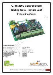
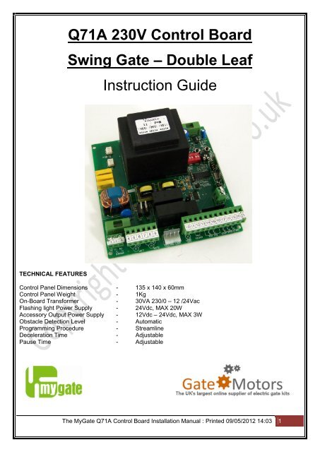
<strong>Q71A</strong> <strong>230V</strong> <strong>Control</strong> <strong>Board</strong><br />
<strong>Swing</strong> <strong>Gate</strong> <strong>–</strong> <strong>Double</strong> <strong>Leaf</strong><br />
Instruction Guide<br />
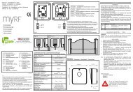
TECHNICAL FEATURES<br />
<strong>Control</strong> Panel Dimensions - 135 x 140 x 60mm<br />
<strong>Control</strong> Panel Weight - 1Kg<br />
On-<strong>Board</strong> Transformer - 30VA 230/0 <strong>–</strong> 12 /24Vac<br />
Flashing light Power Supply - 24Vdc, MAX 20W<br />
Accessory Output Power Supply - 12Vdc <strong>–</strong> 24Vdc, MAX 3W<br />
Obstacle Detection Level - Automatic<br />
Programming Procedure - Streamline<br />
Deceleration Time - Adjustable<br />
Pause Time - Adjustable<br />
The My<strong>Gate</strong> <strong>Q71A</strong> <strong>Control</strong> <strong>Board</strong> Installation Manual : Printed 09/05/2012 14:03 1
Contents<br />
<strong>Q71A</strong> control board layout ........................................................................................................................ 3<br />
Pre-installation checks .............................................................................................................................. 4<br />
Linking Essential Terminals ................................................................................................................... 5<br />
Connecting the motors to the control board ............................................................................................... 6<br />
Connecting the capacitors to the control board ......................................................................................... 7<br />
Photocells ................................................................................................................................................. 8<br />
Photocell positioning .............................................................................................................................. 8<br />
Photocell Wiring .................................................................................................................................... 9<br />
To Use in Closing Cycle ...................................................................................................................... 10<br />
Connecting power to the control board .................................................................................................... 12<br />
Programming the remote control / key-fob .............................................................................................. 13<br />
Saving a new remote controls / key-fobs to the control board .............................................................. 13<br />
Deleting existing remote controls / key-fobs from the control board ..................................................... 13<br />
Changing the code the key-fob transmits ............................................................................................. 14<br />
Remote <strong>Control</strong> Receiver .................................................................................................................... 15<br />
Extended Aerial <strong>–</strong> (optional accessory) ................................................................................................... 15<br />
Fitting the Extended Aerial ................................................................................................................... 15<br />
Selecting the Operating Mode ............................................................................................................. 16<br />
Programming the gates open & closing cycles ........................................................................................ 17<br />
Programming <strong>–</strong> <strong>Double</strong> <strong>Gate</strong>s (for two leafs) ....................................................................................... 17<br />
Setting the Pause Time ....................................................................................................................... 18<br />
Obstacle Detection .............................................................................................................................. 18<br />
Appendix: A ............................................................................................................................................ 21<br />
<strong>Q71A</strong> connection map <strong>–</strong> terminals 1 to 21 ........................................................................................... 21<br />
Appendix: D ............................................................................................................................................ 22<br />
<strong>Q71A</strong> control board <strong>–</strong> FAQ’S ............................................................................................................... 22<br />
Comments & Feedback ........................................................................................................................... 26<br />
The My<strong>Gate</strong> <strong>Q71A</strong> <strong>Control</strong> <strong>Board</strong> Installation Manual : Printed 09/05/2012 14:03 2
<strong>Q71A</strong> control board layout<br />
Map of <strong>Q71A</strong><br />
<strong>Q71A</strong> legend<br />
The My<strong>Gate</strong> <strong>Q71A</strong> <strong>Control</strong> <strong>Board</strong> Installation Manual : Printed 09/05/2012 14:03 3
Pre-installation checks<br />
Thank you for choosing <strong>Gate</strong> <strong>Motors</strong> My<strong>Gate</strong> product for your gate automation needs. This instruction<br />
booklet accompanies every swing gate automation model that uses the <strong>Q71A</strong> control board.<br />
This control board tells the motors what to do and how to behave. The control board has memory chips<br />
onboard which store the key-fob transmitting codes and the parameters the motors will be working to.<br />
These memory chips contain a bare-bones program which literally tells the motors how to walk and talk, but<br />
of course we need to tell the motor how far they are walking and who they will be talking to at the end. This<br />
guide will take you through every step of the installation, one step at a time to ensure that the control board<br />
is wired, configured and operating at full capacity to promote safe and durable working life of your gate<br />
automation system.<br />
With all installations of electrical equipment, your approach should be methodical and concise. Please do<br />
follow this guide correctly, whilst observing personal health and safety for your own protection and for those<br />
around you.<br />
DO NOT use live power to the control board during wiring of the equipment to its terminals<br />
DO NOT touch the control board components or the printed circuit board tracking with your fingertips<br />
DO NOT allow moisture / rain / liquid substances to come into contact with the control board in any manner<br />
This instruction guide is designed to be as simple as possible, including jargon free guidance, to allow you<br />
to follow the complete installation from start to finish at your own pace and leisure to promote perfect<br />
smooth operation of your My<strong>Gate</strong> gate automation system.<br />
The My<strong>Gate</strong> <strong>Q71A</strong> <strong>Control</strong> <strong>Board</strong> Installation Manual : Printed 09/05/2012 14:03 4
So Before We Get Started.....................<br />
Ensure sure you have access to 230v power feed from<br />
your property to the control panels junction box. Cable<br />
used must be 3 core armoured and should be placed<br />
inside a conduit and buried underground to reduce risk<br />
of trip and accidental cutting hazard.<br />
The junction box and control board has been located near<br />
the gates and is mounted and attached to your pillar<br />
securely. This reduces the need for extension cabling to<br />
the motors from the control panel and forms a means of<br />
ease of access to the gate automation control board<br />
should the need arise.<br />
Once the control panel junction box has been fixed into location, and you have power accessible to the<br />
control board, we next look at getting your motors physically operational and ensure they are<br />
communicating efficiently with the control board.<br />
Linking Essential Terminals<br />
In order to activate the gate control board, an essential “link” must be fitted. A “link” in this instance, is a<br />
piece of wire that connects terminals together so that a voltage charge can be distributed from one terminal<br />
to another in order to complete a circuit. Links are placed between terminals on occasions to complete a<br />
circuit to “fool” the control board some equipment is there when it is not.<br />
If you do not have an EMERGENCY STOP button fitted, a link must be placed between terminals 18 & 21<br />
(illustrated below)<br />
The EMERGENCY STOP function is an<br />
ESSENTIAL SAFETY FEATURE and is a<br />
continuous circuit. The quickest way to STOP<br />
the gates if ever an accident was to occur is to<br />
cut all power to the motors <strong>–</strong> like tripping a fuse.<br />
Of course you may not be in a position to<br />
“disconnect the power” to the control board and<br />
this is never recommended.<br />
For Emergency Stop button - <strong>Gate</strong> <strong>Motors</strong> push button switch can be fitted into terminals 18 & 21 (optional<br />
accessory). As soon as the push button is pressed, this breaks the circuit and the control board sees the<br />
broken circuit and IMMEDIATELY STOPS the motors during their operation.<br />
If you do not have an EMERGENCY STOP button and you do not place a link between these two<br />
terminals, the control board “thinks” you have pressed a STOP button and, of course, will halt all operations<br />
<strong>–</strong> regardless to any command you may give it. Be sure to tighten the terminals screws to ensure good<br />
contact is made.<br />
The My<strong>Gate</strong> <strong>Q71A</strong> <strong>Control</strong> <strong>Board</strong> Installation Manual : Printed 09/05/2012 14:03 5
Next stage of the installation is to introduce the motor(s) to the control board. From following your ‘Motor<br />
Installation Guide’ each motor is wired the respective terminals as required for your particular model of<br />
automation. If you do not have this guide to hand, below is a re-cap of connections to the control board<br />
based on the model and which side of the gate is to open first (LEFT HAND / RIGHT HAND)<br />
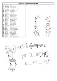
Connecting the motors to the control board<br />
MyAster<br />
MyHook<br />
The My<strong>Gate</strong> <strong>Q71A</strong> <strong>Control</strong> <strong>Board</strong> Installation Manual : Printed 09/05/2012 14:03 6
MyFlow<br />
Connecting the capacitors to the control board<br />
It is essential to wire the capacitors for the motors to the<br />
control board. Typically these are wired into the same<br />
terminals as the Brown (opening) and the Black<br />
(closing) wires. In effect, both will be sharing the same<br />
terminal space. Without the capacitor, the motors will<br />
struggle to start and may “BUZZ” without movement to<br />
the mechanical arm.<br />
Connection illustrated right:<br />
Having attached the motor(s), we can now introduce the photocells to the control board.<br />
The My<strong>Gate</strong> <strong>Q71A</strong> <strong>Control</strong> <strong>Board</strong> Installation Manual : Printed 09/05/2012 14:03 7
Photocells<br />
The My<strong>Gate</strong> photocells are essential for safe use of your gate automation system. These are units that are<br />
comprised of a transmitter and receiver. The photocell transmitter projects an Infrared confined beam in a<br />
straight line and is intercepted by the photocell receiver. The receiver is not a mirrored unit as it absorbs the<br />
Infrared beam. The transmitter and receiver unit must be placed directly opposite each other to have a<br />
clear line of sight and be fixed to the inside of your pillar, just beyond your gate. The photocell then acts as<br />
an “invisible trip-wire” across your drive way, permanently watching for any kind of obstruction. As soon as<br />
the Infrared beam is broken, the “trip-wire” is activated and the motors will immediately stop and will<br />
reverse in their motion. Typically the photocells are used for the closing phase of the gates automated<br />
cycle. “Closing Phase” means that as gates are closing / returning to their original closed position, if your<br />
car stalls in-between the gates or an object / pedestrian moves through the closing gates <strong>–</strong> the gates will<br />
immediately stop and reverse to the full open position at great speed. There is no control over the speed at<br />
which the motors will run. At this stage the control board’s main objective is to get the gates back open as<br />
fast as possible. The gates will continue to be held open until the obstruction has been cleared (the Infrared<br />
beam has been restored) and the control board will continue with its original closing cycle and your gates<br />
will return to their fully closed position.<br />
Photocell positioning<br />
As the transmitter and receiver unit must be directly<br />
opposite each other, typically these units are fixed to<br />
the inside of your pillar, just beyond your gate<br />
(illustrated left). If pillars are not wide enough to<br />
support the fixing of the photocells, do consider<br />
using a <strong>Gate</strong> <strong>Motors</strong> photocell column with rain<br />
hood (optional accessory <strong>–</strong> pictured below):<br />
The photocell pack comes complete with fixings. Each fixing pack contains (illustrated below right):<br />
The photocell pack comes complete with fixings. Each fixing pack contains (illustrated below below):<br />
4 x Threaded screws<br />
4 x Rawlplugs<br />
1 x Photocell Transmitter<br />
1 x Photocell Receiver<br />
The My<strong>Gate</strong> <strong>Q71A</strong> <strong>Control</strong> <strong>Board</strong> Installation Manual : Printed 09/05/2012 14:03 8
Remove the covers of the photocells by removing the facia<br />
fixing screw (circled left)<br />
Photocell Wiring<br />
IMPORTANT SAFETY NOTICE: Please disconnect power to the control board before proceeding.<br />
This reduces the risk of personal shock and any voltage feedback to the control board.<br />
There are two functions the photocells can perform depending on how they are wired to the control board.<br />
Option 1 <strong>–</strong> Closing Phase (photocells placed on the outside of the gates)<br />
Closing Phase means that as gates are closing /<br />
returning to their original closed position, if your<br />
car stalls in-between the gates or an object /<br />
pedestrian moves through the closing gates and<br />
breaks the Infrared beam <strong>–</strong> the gates will<br />
immediately stop and reverse to the full open<br />
position at great speed.<br />
Option 2 <strong>–</strong> Opening Phase (photocells installed on the inside of the gates)<br />
Opening Phase means that as gates are opening, if<br />
your car stalls in-between the gates or an object /<br />
pedestrian moves through the closing gates and<br />
breaks the Infrared beam <strong>–</strong> the gates will<br />
immediately stop and reverse to the full open<br />
position at great speed.<br />
The My<strong>Gate</strong> <strong>Q71A</strong> <strong>Control</strong> <strong>Board</strong> Installation Manual : Printed 09/05/2012 14:03 9
To Use in Closing Cycle<br />
To connect power to Transmitter Unit<br />
Use 1 core wire to connect AC+ on photocell<br />
Transmitter Unit (TX) to Terminal 12.<br />
Use 1 core wire to connect AC- on photocell<br />
Transmitter Unit (TX) to Terminal 13<br />
To connect power to Receiver Unit<br />
Use 1 core wire to connect AC+ on photocell<br />
Receiver Unit (RX) to Terminal 12<br />
Use 1 core wire to connect AC- on photocell<br />
Receiver Unit (RX) to Terminal 13<br />
To connect the relay function to <strong>Control</strong> <strong>Board</strong><br />
Use 1 core wire to connect 3 rd terminal (looking<br />
from left to right) on photocell Receiver Unit (RX)<br />
to Terminal 15<br />
Use 1 core wire to connect 4th terminal (looking<br />
from left to right) on photocell Receiver Unit (RX)<br />
to Terminal 14<br />
IMPORTANT: Please place a link between terminals 16 and 17<br />
To Use in Opening Cycle<br />
To connect power to Transmitter Unit<br />
Use 1 core wire to connect AC+ on photocell<br />
Transmitter Unit (TX) to Terminal 12<br />
Use 1 core wire to connect AC- on photocell<br />
Transmitter Unit (TX) to Terminal 13<br />
To connect power to Receiver Unit<br />
Use 1 core wire to connect AC+ on photocell<br />
Receiver Unit (RX) to Terminal 12<br />
Use 1 core wire to connect AC- on photocell<br />
Receiver Unit (RX) to Terminal 13<br />
To connect the relay function to <strong>Control</strong> <strong>Board</strong><br />
Use 1 core wire to connect 3 rd terminal (looking<br />
from left to right) on photocell Receiver Unit (RX)<br />
to Terminal 17<br />
Use 1 core wire to connect 4th terminal (looking<br />
from left to right) on photocell Receiver Unit (RX)<br />
to Terminal 16<br />
IMPORTANT: Please place a link between terminals 14 and 15<br />
The My<strong>Gate</strong> <strong>Q71A</strong> <strong>Control</strong> <strong>Board</strong> Installation Manual : Printed 09/05/2012 14:03 10
Ensure all wiring is touching the metal contact within each individual terminal block on the control board <strong>–</strong><br />
you can use a Choc Block (terminal strip) as an expansion. The terminals on the control board are narrow<br />
and may have multiple cables in them depending on what other accessories you may be using in<br />
conjunction with your gate automation kit. Please ensure all wires are touching the metal contact strip<br />
within the terminal. This ensures that power can flow through the cable. If you are using a terminal strip,<br />
make sure the cable used to connect the terminal strip to the terminal block is sufficient to carry the current.<br />
Photocell Maintenance - IMPORTANT<br />
Photocells are one piece of equipment supplied with the automation kit that does require regular<br />
maintenance. As they sit on the pillar and quietly operate, they can be forgotten. Faults can occur if<br />
insects, webs, dirt or grease is present in and around the sensors or the case lenses (inside and out). This<br />
scatters the Infrared beam and the control board will interpret this as a warning that an obstacle is present<br />
and the motors will fail to respond to your command <strong>–</strong> this is a safety feature. The motors will not operate if<br />
they believe there is an obstacle that may potentially cause damage.<br />
The photocells are supplied with cable grommets in an attempt to keep the bugs on the outside. Check that<br />
the cases are clean and obstacle free and have the grommets in place. You may find using a silicone<br />
sealant may help to keep the bugs at bay.<br />
At this stage of the installation:<br />
We have our emergency stop link in place<br />
We have wired the motor(s) to the control board<br />
We have wired the photocells to the control board<br />
We can now introduce power to the control board so we can enable the programming of the key-fobs and<br />
the programming of the gate automation opening and closing settings.<br />
The My<strong>Gate</strong> <strong>Q71A</strong> <strong>Control</strong> <strong>Board</strong> Installation Manual : Printed 09/05/2012 14:03 11
Connecting power to the control board<br />
Connecting power to the control board using 1.5mm - 3 core armoured cable 230v.<br />
Cable identification should be:<br />
Colour<br />
Brown<br />
Blue<br />
Yellow / Green<br />
Identification<br />
Live<br />
Neutral<br />
Earth<br />
Insert the Live (brown) wire to terminal 2 and the Neutral (blue) to terminal 3 and tighten the terminal<br />
screws to ensure good safe contact is made. Please connect your Earth (yellow/green) wire to terminal 1.<br />
Please switch the power supply on. After a few seconds you will see three LED’s lit:<br />
DL3 (above terminal 15)<br />
DL4 (above terminal 16)<br />
DL5 (above terminal 18)<br />
DL3 Lit =<br />
DL4 Lit =<br />
Photocells status OK, wiring is complete and control board can see the photocells<br />
2nd set of photocells status is OK, wiring is complete and control board can see the photocells.<br />
If second set of additional photocells are fitted (optional).<br />
If a second set is not used, link must be placed between terminals 16 + 17.<br />
DL5 Lit =<br />
Emergency stop button status OK, wiring is complete and control board can see it.<br />
If an emergency stop button is not fitted, a link must be placed between terminals 18 + 21<br />
Now we look to program the remote control key-fob(s) to the control board.<br />
The My<strong>Gate</strong> <strong>Q71A</strong> <strong>Control</strong> <strong>Board</strong> Installation Manual : Printed 09/05/2012 14:03 12
Programming the remote control / key-fob<br />
<strong>–</strong> Please have your key-fob(s) to hand<br />
Every DOUBLE GATE automation kit comes equipped with 2 MyKey remote controls as standard.<br />
These are three channel Rolling Code remote controls. Rolling Code means<br />
the key fob has multiple combinations (like cut keys for a door lock) at its<br />
disposal which can be changed at anytime digitally. Each channel sends an<br />
individual code on a 433.92 MHz frequency that the control board’s internal<br />
receiver intercepts. The key fob contains 16,000 code combinations.<br />
When the remote control is transmitting, an LED will be seen lit on the<br />
remote control. This is confirmation that the remote control is transmitting.<br />
The remote control is powered by 12v A23 battery with an average life span of 3-5 years depending on<br />
usage.<br />
When the capacity of this battery runs low, you may see the LED transmitting indicator on the key fob lit<br />
faint and the control board may not respond to your command as the signal may be too weak.<br />
Before we program your remote controls to the control board, select one button to act as the activation key<br />
for your gate automation.<br />
On the control board, towards the right hand side,<br />
there are three buttons marked P1, P2 & P3<br />
(illustrated right). These are the control board’s<br />
operational buttons. To program they remote control<br />
to the control board, please follow next set of steps<br />
below:<br />
Saving a new remote controls / key-fobs to the control board<br />
a) Press button P1 on the control panel once and hold for a few seconds then release.<br />
The DL1 light will come on then will go off then come on again. You will hear the relay on<br />
the control board click once. The light will stay on for 10 seconds, allowing 10 seconds to<br />
program the remote control to the control board.<br />
b) Press and hold the button on the remote control until the DL1 light goes off and the relay on<br />
the control board “clicks”.<br />
The control board can store up to 50 remote controls.<br />
Deleting existing remote controls / key-fobs from the control board<br />
a) Press and hold the P1 button, the DL1 light will come on. Keep the button pressed until the<br />
DL1 light goes off.<br />
The My<strong>Gate</strong> <strong>Q71A</strong> <strong>Control</strong> <strong>Board</strong> Installation Manual : Printed 09/05/2012 14:03 13
Changing the key-fob battery<br />
When the capacity of this battery runs low, you may see the LED transmitting indicator on the key fob lit<br />
faint and the control board may not respond to your command as the signal may be too weak. To change<br />
the battery, follow the next set of steps:<br />
1) Turn the key-fob over so it is resting on its front. To the bottom<br />
of the key fob you will see a compartment cover. Using a small<br />
flathead screwdriver, insert this between the casing and the<br />
battery compartment cover to gently release the cover.<br />
2) Obtain size 23A 12V battery from <strong>Gate</strong> <strong>Motors</strong> and replace<br />
like for like. Once the battery is in place replace the compartment<br />
cover.<br />
Changing the code the key-fob transmits<br />
Upon use of the key-fob, if you find that the code the key-fob transmits is not being identified by the control<br />
board, is intermittent in receiving the signal produced or someone else in the immediate area is using (RF)<br />
radio equipment that is transmitting a similar code on the same frequency, you can change the rolling<br />
code that the key-fob transmits. This is achieved by following the next set of steps:<br />
Simultaneously press buttons B and C (about 4-5 seconds) till the<br />
red light of the remote control illuminates.<br />
Hold button B pressed and at the same time release button C and<br />
press it again twice.<br />
The two lights, red and green, should alternating blink to show that<br />
the generation of a new random code succeeded.<br />
Now you can release button B. The remote control is ready to<br />
transmit with a new radio code. N.B. <strong>–</strong> Please delete the previous<br />
stored key fob from the control board<br />
Once this has been completed you must program the key-fob to the control board so it can recognise the<br />
new code generated.<br />
The My<strong>Gate</strong> <strong>Q71A</strong> <strong>Control</strong> <strong>Board</strong> Installation Manual : Printed 09/05/2012 14:03 14
Remote <strong>Control</strong> Receiver<br />
The key-fob signal receiver is built-in to the control panel has a range of up to 30M.<br />
As the signal transmitted from the key-fob is a radio frequency, the signal quality and strength may be<br />
hindered if the control panel for the gate automation is mounted onto a metal plate / bracket or is mounted<br />
against thick concrete pillar, in addition atmospheric conditions (rain / fog) can reduce the strength of the<br />
radio signal. Neighbouring radio signals, especially in built-up areas, can impede the control board’s ability<br />
to single out your key-fob’s code.<br />
If you find the range your radio receiver is having trouble with the interception of your key-fobs transmitting<br />
frequency and code, a My<strong>Gate</strong> Extended Aerial can be fitted to your receiver unit.<br />
Extended Aerial <strong>–</strong> (optional accessory)<br />
The <strong>Gate</strong> <strong>Motors</strong> extended aerial substitutes the<br />
standard internal aerial to extend the range of<br />
your transmitters to 80m (max) in free field<br />
conditions. Typically mounted on top of the gate<br />
pillar, the 2M coaxial cable length makes this unit<br />
easy to install on a variety of applications. Using<br />
its “L” shaped bracket, the extended aerial is<br />
very versatile as it can be mounted on top of<br />
pillars, fence posts, or any other structure near<br />
your gates that is elevated.<br />
Fitting the Extended Aerial<br />
Fitting of the Extended Aerial is very simple and effective.<br />
Simply remove existing white aerial wire by using a small<br />
flat head screwdriver to loosen its terminal screw and take out<br />
the aerial cable.<br />
Place the Extended Aerial coaxial cable into terminal 23<br />
(Illustrated left).<br />
Twist the braiding from the Extended Aerial and place into<br />
terminal 22.<br />
The My<strong>Gate</strong> <strong>Q71A</strong> <strong>Control</strong> <strong>Board</strong> Installation Manual : Printed 09/05/2012 14:03 15
Selecting the Operating Mode<br />
Before we program the opening / closing cycles, we first need to establish the cycles operating mode.<br />
The operating mode is selected through DS1 dipswitches.<br />
The switches are located to the right<br />
hand side of the control board (illustrated right):<br />
There are three different operating modes:<br />
Step by Step<br />
Automatic Closing<br />
Automatic Closing with Multi-occupation<br />
STEP by STEP Mode (Automatic closing turned off)<br />
This operating function turns off the automatic closing. When a START command is given by pressing<br />
remote control button or<br />
A first START command makes the gate OPEN.<br />
A second START command while the gate is opening will STOP the gate.<br />
A further START command makes the gate CLOSE.<br />
A START command while the gate is closing will STOP the gate.<br />
To select this operating mode place the DS1 dip-switches as shown right:<br />
1=OFF<br />
2=OFF<br />
3=OFF<br />
AUTOMATIC CLOSING Mode<br />
A first START command makes the gate OPEN, once the gate has reached the<br />
complete opening it stops and the PAUSE-TIME starts.<br />
When the pause-time elapses the gate automatically CLOSES.<br />
If a START command is given while the gate is opening, the gate STOPS still.<br />
A further START command makes the gate CLOSE.<br />
If a START command is given while the gate is closing, the gate STOPS and<br />
REVERSES in about 1.5 seconds.<br />
To select this operating mode place the DS1 dip-switches as shown right:<br />
1=OFF<br />
2=ON<br />
3=OFF<br />
The My<strong>Gate</strong> <strong>Q71A</strong> <strong>Control</strong> <strong>Board</strong> Installation Manual : Printed 09/05/2012 14:03 16
AUTOMATIC CLOSING mode with MULTI-OCCUPATION Function<br />
A first START command makes the gate OPEN, once the gate has reached the<br />
complete opening it stops and the PAUSE-TIME starts.<br />
When the pause-time elapses the gate automatically CLOSES.<br />
A START command given while the gate is opening has no effects.<br />
A START command given whilst the gate is closing makes the gate STOP and<br />
REVERSE in its direction - this may take about 1.5 seconds to action.<br />
To select this operating mode place the DS1 dip-switches as shown right:<br />
1=ON<br />
2=ON<br />
3=OFF<br />
Now we look to program your gates opening & closing cycles and allow the control board to become<br />
familiar with the operating of your gate automation by pushing and pulling the weight of your gate leaf(s) to<br />
ascertain the correct level of obstacle detection required and calculate the time period required to complete<br />
the opening and closing operation.<br />
Programming the gates open & closing cycles<br />
At this stage of the installation we have:<br />
We have our emergency stop link in place<br />
We have wired the motor(s) to the control board<br />
We have wired the photocells to the control board<br />
We have programmed the key-fob remotes<br />
We have set the gate operation mode<br />
Now we look to program the automation cycles. The programming sequence is a short and fully automatic<br />
process. Please have your key-fob close to hand and read the next set of instructions thoroughly before<br />
proceeding.<br />
Programming <strong>–</strong> <strong>Double</strong> <strong>Gate</strong>s (for two leafs)<br />
Make sure that the gate is fully closed.<br />
a) Press Button P2 and hold. The DL1 LED light comes on and stays on for a few seconds and then<br />
goes off. When the DL1 light turns of, release button P2. The motors will initially work in the<br />
opposite direction (over close) for a few seconds before stopping and then travelling in the right<br />
direction (opens the gate). This is normal programming operation and is critical to the continued<br />
operation of the gates as the control board is determining its start position by pushing your gate leaf<br />
against your centre gate stop.<br />
The My<strong>Gate</strong> <strong>Q71A</strong> <strong>Control</strong> <strong>Board</strong> Installation Manual : Printed 09/05/2012 14:03 17
) During the first 8 seconds of the opening cycle, the motor is travelling slowly. This is the control<br />
board calculating the ‘deceleration speed’ required for the motor. Use the RV1 adjuster<br />
to adjust the deceleration speed accordingly (clockwise to increase speed of motor,<br />
anti-clockwise to increase deceleration speed)<br />
c) After the 8 second period, the motor will then operate at full speed. The control board’s relays will<br />
“click” quickly. Use the RV1 to set the torque force required for the motor to move the physical<br />
weight of your gate leaf. It is critical for the motor to just push the weight of the gate and not to over<br />
set the torque. If the torque is too high, the obstacle detection facility will be compromised and will<br />
not function accordingly therefore leaving the safety of the gate operation at risk.<br />
d) After a short time after opening, the gates will close automatically: the control boards relays will<br />
“click” slowly.<br />
e) Once the gates have closed, the control board automatically saves the settings.<br />
Now we need to set the pause time. This is the time taken where the gates are open before<br />
automatically closing <strong>–</strong> of course this will only be active if you have set the gate operation mode to<br />
Automatic Closing / Automatic Closing with Multi-occupation.<br />
Setting the Pause Time<br />
a) Press button P3 and hold until the DL1 LED is lit and stays lit. Once permanently lit, release the<br />
button.<br />
b) Count down the seconds the gates are to stay open before automatically closing and then press<br />
button P3 again. The DL1 LED will turn off.<br />
If you need to change the pause time, please repeat the above steps.<br />
It is essential after completing the installation programming process to run a complete open and<br />
close cycle before general use.<br />
The control board is self-learning and needs to use the very first full cycle to use as a “bench mark” for<br />
future operations. It is during this process the control board is calibrating the level of obstacle detection<br />
required.<br />
Obstacle Detection<br />
The <strong>Q71A</strong> features built-in obstacle detection during opening and closing cycles. This feature is present<br />
during the whole gates operation and cannot be turned off. The control board automatically adjusts the<br />
detection sensibility according to the force required to the motor to physically move the gate. The obstacle<br />
detection operates by measuring the force required to move the weight of the gate and detects resistance if<br />
the gate becomes obstructed. The gate reacts by stopping in its motion, waits for a 1 / 2 seconds and then<br />
reverses in its travel for between 1 / 2 cm’s to allow the obstruction trapped to be safely removed.<br />
The gate will not continue to operate UNTIL you have pressed your key fob button or give another start<br />
signal. The control board will then continue to complete the cycle it was in before the obstruction happened.<br />
There are incidences where the Obstacle Detection level can be sensitive when the gate is about to fully<br />
open / close (gate leaf rests against gate stop). When the motor is decelerating, it is using a quarter of its<br />
The My<strong>Gate</strong> <strong>Q71A</strong> <strong>Control</strong> <strong>Board</strong> Installation Manual : Printed 09/05/2012 14:03 18
power consumption. Therefore even the friction created by the coming into contact with your gate stops<br />
may trigger the obstacle detection system and the gates will reverse.<br />
This sensitivity during deceleration of the motors can be adjusted with ease by simply moving the DIP<br />
switches marked on the control board as DS2 (illustrated below):<br />
Sometimes anomalies are encountered during the normal duty cycle, for example:<br />
<strong>Gate</strong> stops and reverses before completing full travel when opening<br />
<strong>Gate</strong> stops and reverses just after starting<br />
Repeated ‘stop & reverse’ incidences are specifically seen in cases where heavy gates are being<br />
automated and/or gates with hinges that adds friction to the gates motion and sudden temperature falls.<br />
It is possible to reduce the sensibility level of the obstacle detection applying the following procedure:<br />
1) Keep buttons P1 & P2 pressed at the same time - the Led DL1 will blink a certain number of times<br />
(example: 10 blinks), then let go of P1 & P2 and keep a note of the amount of times the light blinks.<br />
2) After the DL1 light has stopped blinking, press P1 as many times as the number of blinks seen <strong>–</strong><br />
then add 3 additional times (example: 10 + 3 = 13 times). Every press of the P1 button corresponds<br />
to the blinking of the DL1 light.<br />
3) Confirm the procedure by pressing button P2<br />
The procedure is now completed and the level of the obstacle detection has been reduced. If the anomalies<br />
continue to re-occur (false and repeated stops / reversing) repeat the same procedure again up to step 2,<br />
and then follow step 2 but instead of adding 3 additional strokes of the P1 button, this time increase by<br />
more.<br />
The Obstacle Detection feature on this control board is completely self-learning. Please remember that it is<br />
essential after completing the installation programming process to run a complete open and close cycle<br />
before general use.<br />
The My<strong>Gate</strong> <strong>Q71A</strong> <strong>Control</strong> <strong>Board</strong> Installation Manual : Printed 09/05/2012 14:03 19
Have you tried the gate automation’s full open & close cycle for the first time since completion of<br />
the programming?<br />
Did the gate(s) open and close perfectly?<br />
If the gates timing was not as perfect as you would like, please repeat the programming process from step<br />
“a)”. The completion of the programming sequence will replace any previously saved settings.<br />
Have you tried and tested the gates Obstacle Detection after completing the first cycle since<br />
completion of the programming?<br />
If the gates did not respond as quickly as you would of hoped, please repeat the programming process fro,<br />
step “a)” paying particular attention to the position of the RV1 trimmer for the torque setting. Adjust this<br />
trimmer switch to a lower position. The motors may be providing more psuh and pull power than they need<br />
to be for the weight of your gate.<br />
To recap:<br />
The emergency stop link in place<br />
The photocells have been wired to the control board<br />
The motor(s) have been wired to the control board<br />
The remote controls have been programmed the control board<br />
The opening & closing cycles have been programmed<br />
The opening & closing cycle has been tested<br />
The Obstacle detection level / setting has been tested<br />
Your installation is now complete!<br />
The My<strong>Gate</strong> <strong>Q71A</strong> <strong>Control</strong> <strong>Board</strong> Installation Manual : Printed 09/05/2012 14:03 20
Appendix: A<br />
<strong>Q71A</strong> connection map <strong>–</strong> terminals 1 to 21<br />
Map showing connections for:<br />
Motor 1 & Motor 2 (Included with Kit)<br />
Safety Photocells (Included with Kit)<br />
Electro-Lock & MEL unit (Optional Accessory)<br />
Flashing light (Optional Accessory)<br />
Extended Aerial (Optional Accessory)<br />
The My<strong>Gate</strong> <strong>Q71A</strong> <strong>Control</strong> <strong>Board</strong> Installation Manual : Printed 09/05/2012 14:03 21
Appendix: D<br />
<strong>Q71A</strong> control board <strong>–</strong> FAQ’S<br />
Photocells <strong>–</strong> Do I need to use the photocells that come with the kit?<br />
Included in each double and single gate automation kit is a pair of safety photocells <strong>–</strong> one transmitter cell<br />
and one receiver cell. The transmitter projects an Infrared beam direct across the drive way to the receiver<br />
unit. These units should be mounted on each gatepost, directly opposite each other. This creates an<br />
invisible “Trip Wire” that detects any obstacles that comes into its path. As soon as the beam is broken, the<br />
relay in the receiver sends a signal to the control board telling it there is an obstruction. If the gates are in<br />
their fully closed or open position, the breaking of the photocell beam will stop any automation from<br />
commencing until the obstacle is/has cleared. If the beam is broken during the automated open / close<br />
cycle, the breaking of the beam triggers the relay in the receiver to send a signal to the control board telling<br />
it there is an immediate obstruction. The motors will instantly stop and begin to reverse. Once the motors<br />
have reversed fully, the motors will stop and will stay still until the photocell receiver can see the beam<br />
transmitted from its opposite unit. Once the beam is seen again, unbroken, the motors will continue to<br />
complete their original cycle. The photocells are an important safety feature and must be installed <strong>–</strong> at all<br />
times.<br />
If you have large / deep gates then an additional pair of photocells should be purchased and mounted on<br />
posts just beyond the leading edges of the open gate. These will protect the full radial sweep of the gate.<br />
Photocells - My gates are not working, I cannot see LED DL3 Lit. What can I do?<br />
When DL3 light is not seen, this is the board telling us that the photocell beam is broken / there is an<br />
obstacle. Without this resolved, the motors will not work <strong>–</strong> this is a safety feature. Make sure there are no<br />
obvious obstructions breaking the beam(s) <strong>–</strong> custom brackets, branches etc. If there are no obstructions<br />
then we need to look closely at the photocells themselves <strong>–</strong> this includes removing the covers of the<br />
photocells and looking to see if insects, webs, dirt or grease is present in and around the sensors or the<br />
case lenses (inside and out). Photocells are supplied with cable grommets in an attempt to keep the bugs<br />
on the outside. Check that the cases are clean and obstacle free.<br />
Heavy rain and direct sunlight may cause disruption to the photocell Infrared beam. An attempt to stop the<br />
disruption can be made by using a hood protector to cover the photocells.<br />
Photocells should not be installed where direct sunlight may affect their use.<br />
Key-fob <strong>–</strong> I am pressing the button but my gates are not opening, what can I do?<br />
If your key-fob is new, check that it has been programmed to the control board. If not, please follow<br />
instruction below:<br />
a) Press button P1 on the control panel once and hold for a few seconds then release. The DL1<br />
light will come on then will go off then come on again. You will hear the relay on the control board<br />
click once. The light will stay on for 10 seconds, allowing 10 seconds to program the remote control<br />
to the control board.<br />
b) Press and hold the button on the remote control until the DL1 light goes off and the relay on the<br />
control board “clicks”.<br />
If the key-fob has been programmed to the control board and has been working fine before, check the keyfob<br />
indicator LED is alit when you are pressing the button. If the light is not seen or is faintly illuminated,<br />
please change the battery. Remove the small screw on the reverse side of the key-fob and remove the keyfob<br />
cover, this will show the battery compartment.<br />
The My<strong>Gate</strong> <strong>Q71A</strong> <strong>Control</strong> <strong>Board</strong> Installation Manual : Printed 09/05/2012 14:03 22
Weather condition - As the key-fob remotes function by transmitting a radio frequency signal to the control<br />
board, signal quality can be diminished as a result of poor weather; rain, fog and in some cases electrical<br />
storms. In these situations, capture range can reduce to as little as 5M. Using an extended aerial will<br />
increase capture range to 80M in all weather.<br />
Key-fob - My gates are opening randomly for no reason, is someone else using my key-fob signal?<br />
With any unit that transmits a radio frequency, there are incidences where radio receiving equipment<br />
catches the signal and thinks it is intended for that unit by recognizing the coding contained within that<br />
frequency it has intercepted. In this case, the gate control board radio receiver unit has collected a signal<br />
that is similar if not almost the same as the one your key-fob is transmitting and believes it is being told to<br />
open by you.<br />
The key-fobs transmit a 433,92Mhz frequency and are DIP switch operated. To resolve this clash of<br />
signals, we need to give the control board another code to recognize. This is done in three steps:<br />
Step 1: Deleting your existing key-fob code.<br />
- Press button P1 on the control board until DL1 light comes on. Keep this button pressed for a<br />
further 10 seconds, the DL1 light will go out. This is confirmation all key fob codes have been<br />
deleted.<br />
Step 2: Re-modulating the frequency code<br />
On the reverse side of your key-fob’s casing is a small metal screw. Remove the screw and remove the<br />
front cover of the key-fob. Please be careful when removing the key-fob cover as the tactile switch circular<br />
button covers are loose and may fall out from their place.<br />
Look towards the bottom of the key-fob’s printed circuit board (PCB) and you will see a row of white tiny<br />
DIP switches. By moving the DIP switches, the key-fob will transmit a different coded frequency. Use a pin<br />
or tip of pencil to move a few of these switches up and down. Re-attach the key-fobs case, paying attention<br />
to the alignment of the tactile switch covers and screw the case tightly in place.<br />
Step 3: Programming the control board to accept your key-fob signal<br />
a) Press button P1 on the control panel once and hold for a few seconds then release. The DL1<br />
light will come on then will go off then come on again. You will hear the relay on the control board<br />
click once. The light will stay on for 10 seconds, allowing 10 seconds to program the remote control<br />
to the control board.<br />
b) Press and hold the button on the remote control until the DL1 light goes off and the relay on the<br />
control board “clicks”.<br />
Key-fob - What range does the remote key-fob have?<br />
The radio frequency range is 30m from the key-fob, on an ideal day. As the key-fob remotes function by<br />
transmitting a radio frequency signal to the control board, signal quality can be diminished as a result of<br />
poor weather including rain or fog and in some cases electrical storms. In these situations, capture range<br />
by the built-in aerial can reduce to as little as 5m. Using the <strong>Gate</strong> <strong>Motors</strong> Extended Aerial in conjunction<br />
with your automation kit will ensure up to 80m signal capture range in all conditions.<br />
Key-fob <strong>–</strong> What are the extra buttons on the remote key-fob for?<br />
To avoid having to carry around a pile of different remote controls for your other remote devices, these<br />
buttons may be programmed to open a second gate, a garage door, outside lighting, etcetera. In order for<br />
these devices to work with the MyKey key-fob remotes, each device will need an additional radio receiver.<br />
The My<strong>Gate</strong> <strong>Q71A</strong> <strong>Control</strong> <strong>Board</strong> Installation Manual : Printed 09/05/2012 14:03 23
Aerial - What does the extended aerial do and do I need one?<br />
The extended aerial boosts the radio frequency capture range to 80m in all weather conditions. As the keyfob<br />
remotes function by transmitting a radio frequency signal to the control board, signal quality can be<br />
diminished as a result of poor weather. The improved signal capture range can also help for installations<br />
where there is a long drive way to the gates or you need to open the gates much before you arrive.<br />
Intercoms<strong>–</strong> I have an intercom system, how do I connect it to my gate?<br />
Power<br />
Your intercom system may already be powered by separate source. If you are fitting a new intercom, the<br />
<strong>Q71A</strong> control board has 12/24vdc power outputs available for fueling such equipment that requires<br />
12/24vdc to function. Terminal 12 (power positive) and terminal 13 (power negative) provide the power<br />
output. Check with your intercom install guide for suitability.<br />
Opening the gate<br />
Your intercom should have 2 sets of outputs for unlocking MAG locks (labeled as C <strong>–</strong> Common & N/C -<br />
Normally Closed) and for switching volt free contact equipment (labeled as C <strong>–</strong> Common, N/O - Normally<br />
Open). To connect the intercom to the <strong>Q71A</strong> control board for opening the gate from your intercom<br />
handset:<br />
Intercom - <strong>Q71A</strong> Terminals<br />
C (Common) - 21<br />
N/O (Normally Open) - 20<br />
Digital Keypads <strong>–</strong> I have a keypad for coded access, how do I connect it to my gate?<br />
Power<br />
Your digital keypad system may already be powered by separate source. If you are fitting a new digital<br />
keypad, the <strong>Q71A</strong> control board has 12/24vdc power outputs available for fueling such equipment that<br />
requires 12/24vdc to function. Terminal 12 (power positive) and terminal 13 (power negative) provide the<br />
power output. Check with your digital keypad install guide for suitability.<br />
Opening the gate<br />
Your digital keypad should have 2 sets outputs for unlocking MAG locks on doors (labeled as C <strong>–</strong> Common<br />
& N/C - Normally Closed) and for switching volt free contact equipment (labeled as C <strong>–</strong> Common, N/O -<br />
Normally Open). To connect the digital keypad to the <strong>Q71A</strong> control board for opening the gate by entering<br />
your pin code:<br />
Intercom - <strong>Q71A</strong> Terminals<br />
C (Common) - 21<br />
N/O (Normally Open) - 20<br />
The My<strong>Gate</strong> <strong>Q71A</strong> <strong>Control</strong> <strong>Board</strong> Installation Manual : Printed 09/05/2012 14:03 24
Will my gates still open in the winter when it is very cold and icy?<br />
Climate conditions do affect how the internal mechanics operate. During periods where the outside<br />
temperature can drop as low as -20 in some parts of the UK, the motors can physically have trouble<br />
starting, just like a motor vehicle. Although the internal gears are protected by machine grease, of course<br />
anti-freeze cannot be used. If the motors do struggle to push and pull the gates and you are finding them<br />
closing short or opening short, a simple adjustment to the torque force is required to give the motors an<br />
extra helping hand. This adjustment will increase the power output to the motor to help it mobilise. During<br />
the summer season or where the temperature increases, this torque force adjustment may need to be<br />
reversed as the mechanics will be able to move a lot more freely and you may find your gates closing<br />
quicker or over closing / opening. For the MyDiamond and MyAster, if you are finding ice forming on the<br />
motor arms, wiping the arm with liquid paraffin will help reduce ice formation. Due to the unique way the<br />
motors are fabricated, no ice will get into the motor via the arms, however if it has settled and compacts<br />
when the arm retracts to open your gate, the ice build-up may force the arm not to fully retract.<br />
What happens if there is a power cut?<br />
In the event of a power cut, naturally the gate automation kit will not function. Once the automation kit has<br />
completed either a closing or opening cycle, the arms are locked into position. All <strong>Gate</strong> <strong>Motors</strong> automation<br />
kits have an emergency release system, where a special key is used to disengage the motor gearing from<br />
its mechanical arm to allow the gates to be opened manually.<br />
Always remember to re-engage the emergency release when power has been restored. If the release is not<br />
engage, the motor(s) will fail to operate.<br />
If the power cut is a result of a grid surge and you find the gate automation kit ceases to function once<br />
power has been restored, check the quick blow fuses on the control board to ensure these have not blown.<br />
Do the motors need maintaining?<br />
Unlike hydraulic motors, the <strong>Gate</strong> Motor gate automation kits are electromechanical motors and do require<br />
periodic maintenance including cable checks to make sure there are no breaks, chew marks from animals<br />
and make sure the motors are free from dirt, free from fallen branches from neighbouring trees and other<br />
obstacles that could pose as a risk to the efficient working of the gate motors.<br />
Following practical maintenance will ensure continued uninterrupted automation service.<br />
The My<strong>Gate</strong> <strong>Q71A</strong> <strong>Control</strong> <strong>Board</strong> Installation Manual : Printed 09/05/2012 14:03 25
Comments & Feedback<br />
We thank you for taking the time in reading and following the new version of our instructions. This<br />
instruction guide has been compiled from comments and feedbacks received from previous / existing<br />
customers who are familiar with our automation and had followed the old version (also included alongside<br />
with this guide). The aim of this guide is to appeal to all “walks” of life - from end users to Tradesmen. We<br />
understand that not everyone can follow complex wiring diagrams and often instructions can be over<br />
complicated. We, at <strong>Gate</strong> <strong>Motors</strong>, feel that a “one size fits all” guide, with simple straight forward jargon-free<br />
would benefit the customer & installers alike and promote safe operation of the automation.<br />
Your feedback is valuable to us to help us with continued development and fine tuning of our instructions to<br />
suit customers’ needs.<br />
If there is a subject or topic relating to the control board and its functions that you feel we could include, rewrite<br />
or present in a different way, please let us know by email on sales@gatemotors.co.uk.<br />
For more information on <strong>Gate</strong><strong>Motors</strong> full line of automatic gate openers and access controls visit our website at<br />
www.gatemotors.co.uk<br />
Phone Sales Lines<br />
UK: 01202 717191<br />
Outside UK: (+44)1202 717191<br />
Phone Technical Lines<br />
UK: 0905 235 1700* (service available 8:30am to 5:30pm Monday to Friday only, closed Weekends and Public Holidays)<br />
ROI: 156 099 9667** (service available 8:30am to 5:30pm Monday to Friday only, closed Weekends and Public Holidays)<br />
Email: support@gatemotors.co.uk<br />
*UK calls to this number are billed by the second and cost £1.02 per minute from a standard landline; other networks charges may also apply.<br />
**IRISH calls to this number are billed by the second and cost €1.25 per minute from a standard landline; other networks charges may also apply.<br />
Service is provided by Digital Select Ltd, 271 Regent Street, London, W1B 2ES whose helpline number is 0844 448 0165<br />
Trading address: <strong>Gate</strong><strong>Motors</strong> UK, Unit 16c, Chalwyn Industrial Estate, St. Clements Road, Poole, Dorset. BH12 4PE.<br />
<strong>Gate</strong><strong>Motors</strong> is the trading name of Screwjack Limited - registered office at 21 Oxford Road, Bournemouth, Dorset. BH8 8ET.<br />
Registered # is 4287804, VAT #:785 3450 06<br />
The My<strong>Gate</strong> <strong>Q71A</strong> <strong>Control</strong> <strong>Board</strong> Installation Manual : Printed 09/05/2012 14:03 26