What is TDX Drill
What is TDX Drill
What is TDX Drill

Create successful ePaper yourself
Turn your PDF publications into a flip-book with our unique Google optimized e-Paper software.
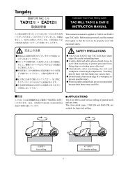
<strong>TDX</strong>-type TAC <strong>Drill</strong> Manual<br />
TAC DRILL Manual<br />
DW chipbreaker<br />
DS chipbreaker<br />
DJ chipbreaker
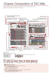
CONTENTS<br />
<strong>What</strong> <strong>is</strong> <strong>TDX</strong> <strong>Drill</strong> ? ··········································· 1<br />
• Nomenclature for TAC <strong>Drill</strong> ········································· 1<br />
• Cutting mechan<strong>is</strong>m of TAC <strong>Drill</strong> ································· 1<br />
Features of <strong>TDX</strong> <strong>Drill</strong> ········································· 2<br />
Components of <strong>TDX</strong> <strong>Drill</strong> series ···························· 3<br />
• Body ··········································································· 3<br />
• Inserts ········································································· 3<br />
• Optional components ················································· 3<br />
Features of drill body ········································ 4<br />
Features of chipbreakers ··································· 5<br />
• DJ chipbreaker ··························································· 5<br />
• DS chipbreaker ··························································· 5<br />
• DW chipbreaker ·························································· 5<br />
Application area of each chipbreaker type ·············· 6<br />
Features and applications of insert grades ·············· 6<br />
Insert selection guide ······································· 7<br />
Recommended cutting conditions ························· 7<br />
• Points to consider ······················································ 7<br />
Chip shapes···················································· 8<br />
• Chip shapes produced by central edge ····················· 8<br />
• Chip shapes produced by peripheral edge ················ 9<br />
Medium to high carbon steels, alloy steels, etc.<br />
Stainless steels, low carbon steels, low alloy steels, etc.<br />
• Chip control for snarled chips ·································· 10<br />
• Chip control for low carbon steels at low cutting speeds ·········· 11<br />
• Chip control for aluminum alloys ······························ 12<br />
Chip shapes (DW chipbreaker)····························· 13<br />
• Compar<strong>is</strong>on of chip shapes at high feeds ················ 13<br />
• Chip shapes at normal conditions ···························· 13<br />
• Chip shapes of stainless steels, alloy steels,<br />
and low carbon steels ·············································· 13<br />
Cutting performance of long body types ················· 14<br />
Selection of L/D in drill specifications ··················· 15<br />
Machining data ·············································· 16<br />
• Tool life compar<strong>is</strong>on in drilling alloy steel ················· 16<br />
• Tool life compar<strong>is</strong>on in drilling stainless steel ·········· 16<br />
• Improvement in drilling of stainless steel ················· 16<br />
• Machining of hardened steel with small diameter (ø 13 mm) drill ····· 17<br />
• Machining example of hardened steel ····················· 17<br />
• Improvement in drilling of hard cast iron ·················· 17<br />
• Deep hole drilling of low carbon steel<br />
with large-diameter (ø 50 mm) drill ··························· 18<br />
• MQL deep-hole drilling of carbon steel with<br />
small diameter (ø 12.5 mm) drill ······························· 18<br />
• High-efficiency drilling with DW insert (GH730) ······· 19<br />
Fin<strong>is</strong>hed hole diameters ···································· 20<br />
Determination of tool life ·································· 21<br />
• Tool life determination for insert ······························· 21<br />
• Tool life determination for drill body ························· 22
Cutting forces ················································ 22<br />
Surface fin<strong>is</strong>h ················································ 23<br />
Shapes of hole bottom ······································ 24<br />
Use of <strong>TDX</strong> drill on machining centers ··················· 24<br />
• Selecting toolholders ················································ 24<br />
• Adjusting drilling diameter ········································ 24<br />
Use of <strong>TDX</strong> drill on lathes ·································· 25<br />
• Mounting of drill body on turret (tool post) ··············· 25<br />
• Checking of cutting edge height ······························ 25<br />
• Checking of setting conditions by try machining ····· 26<br />
• Adjusting of cutting edge height ······························ 26<br />
Offset machining on lathes ································ 27<br />
• Offset machining ······················································ 27<br />
Cautions when using on lathes ···························· 28<br />
• Through-hole drilling ················································ 28<br />
• When a d<strong>is</strong>c-like uncut piece <strong>is</strong> left on the exit side ········ 28<br />
• When machining a large-diameter hole<br />
in excess of the maximum drilling diameter ············· 28<br />
• When using <strong>TDX</strong> drill on lathe<br />
without internal coolant supply ································ 28<br />
Special machining ··········································· 29<br />
• Surface conditions to be machined ························· 29<br />
• <strong>Drill</strong>ing of interrupted hole ········································ 29<br />
• <strong>Drill</strong>ing of stacked plates ·········································· 30<br />
• Enlarging of drilled hole ············································ 30<br />
MQL machining ·············································· 31<br />
• <strong>What</strong> <strong>is</strong> “MQL” machining ? ····································· 31<br />
• Cautious points in selecting drilling conditions ········ 31<br />
Cautious points in use ······································ 32<br />
• Cutting fluids ···························································· 32<br />
• Maximum drilling depth ············································ 32<br />
• Machining of through hole ········································ 32<br />
• <strong>Drill</strong>ing through-hole on work-rotating condition······ 32<br />
Troubleshooting ·········································· 33,34<br />
Specifications of <strong>TDX</strong> drills ································ 35<br />
• L/D=2 (metric) ··························································· 35<br />
• L/D=2 (inch) ······························································ 36<br />
• L/D=3 (metric) ··························································· 37<br />
• L/D=3 (inch) ······························································ 38<br />
• L/D=4 (metric) ··························································· 39<br />
• L/D=5 (metric) ··························································· 40<br />
Test report format ··········································· 41<br />
Specifications of inserts for <strong>TDX</strong> drills ·················· 42<br />
EZ-sleeves specially designed for <strong>TDX</strong> drills ··········· 42<br />
• Use EZ sleeves for the following purposes ·············· 42<br />
• Setting of EZ sleeve·················································· 43<br />
• Specifications ··························································· 43<br />
CONTENTS
<strong>What</strong> <strong>is</strong> <strong>TDX</strong> <strong>Drill</strong> ?<br />
• A drill which has dual indexable-inserts configured on the front end of a steel holder.<br />
• Both inserts share the cutting zone.<br />
• Insert grades and geometries can be selected to suit the machining situation.<br />
Nomenclature for TAC <strong>Drill</strong><br />
Flange diameter<br />
Shank<br />
Peripheral insert<br />
Maximum drilling depth<br />
Overall length<br />
Shank length<br />
<strong>Drill</strong> diameter<br />
Shank diameter<br />
Central insert<br />
Flute<br />
Flange<br />
Taper pipe thread ( PT screw )<br />
Cutting mechan<strong>is</strong>m of TAC <strong>Drill</strong><br />
Central insert<br />
Peripheral insert<br />
Central insert<br />
Cutting zone of central edge<br />
Cutting zone of<br />
peripheral edge<br />
Peripheral insert<br />
<strong>Drill</strong> diameter øD<br />
1
Features of <strong>TDX</strong> <strong>Drill</strong><br />
Outstanding economy<br />
Four cutting edges per insert can be<br />
economically utilized by indexing it as<br />
shown below.<br />
Exceptional chip control<br />
The newly designed 3-dimensional<br />
chipbreakers provide exceptional chip control<br />
over a wide range of work materials.<br />
Specially designed chip pocket helps to<br />
effectively remove chips from the cutting zone.<br />
Peripheral insert<br />
Insert<br />
changing<br />
Indexing<br />
Central insert<br />
Stable drilling and low vibration<br />
Can enter the cut smoothly with less<br />
vibration and allows stable machining.<br />
Exceptional reliability<br />
The thicker insert design increases impact<br />
res<strong>is</strong>tance and extends tool life.<br />
Good surface quality<br />
The stable cutting balance allows excellent<br />
chip evacuation and good surface fin<strong>is</strong>h.<br />
2
Components of <strong>TDX</strong> <strong>Drill</strong> series<br />
Body<br />
Only Tungaloy offers a full lineup of drill diameters (ø12.5 to ø54.0)<br />
and L/D ratios (2, 3, 4 and 5) !<br />
Unavailable<br />
<br />
<br />
<br />
Competitive indexable insert drills<br />
<br />
<strong>Drill</strong> diameter<br />
Inserts<br />
Three types of chipbreaker geometries and four insert grades are<br />
available. Inserts are selectable from the eight combinations of grades<br />
and chipbreaker types.<br />
Chipbreaker types<br />
Grades<br />
AH740<br />
AH120<br />
DJ<br />
<br />
DS<br />
<br />
DW<br />
<br />
<br />
<br />
<br />
GH730<br />
T1015<br />
<br />
<br />
<br />
<br />
<br />
Optional components<br />
Eccentric sleeves specifically designed for the <strong>TDX</strong> drills extend<br />
the application range.<br />
<br />
<br />
3
Features of drill body<br />
New drills specially designed for deep holes have realized stable<br />
drilling of deep holes up to 5 times the drill diameters !!<br />
Ideally balanced design<br />
Higher reliability<br />
Ex<strong>is</strong>ting 4-corner inserts can be economically<br />
used for these new drills.<br />
The design of the insert configuration allows<br />
stable deep hole drilling up to 5<br />
times the drill diameter.<br />
Excellent chip control<br />
New oil-hole design and increased crosssectional<br />
area of the flute have vastly improved<br />
chip evacuation ability.<br />
Highly rigid tool design<br />
By optimizing the flute design, the deflection<br />
of the drill body could be suppressed<br />
to a minimum.<br />
Example of stable drilling with small diameter drill<br />
Spindle power consumption (A)<br />
15<br />
10<br />
5<br />
0<br />
Entrance<br />
Amount of oversize<br />
Spindle power<br />
consumption<br />
1.0<br />
0.8<br />
0.6<br />
0.4<br />
0.2<br />
0<br />
Bottom<br />
<strong>TDX</strong><br />
<br />
<br />
Amount of oversize (mm)<br />
Competitor “A” (ø13)<br />
15<br />
10<br />
5<br />
0<br />
Entrance<br />
Amount of oversize<br />
Spindle power<br />
consumption<br />
1.0<br />
0.8<br />
0.6<br />
0.4<br />
0.2<br />
0<br />
Amount of oversize (mm)<br />
Bottom<br />
Competitor “A” (ø13)<br />
Machine : Vertical machining<br />
center (BT50)<br />
Work material : High carbon steel<br />
(JIS S55C)<br />
<strong>Drill</strong>ing depth : 52 mm<br />
(L/D=4, Blind hole)<br />
Cutting speed : Vc=150 m/min<br />
Feed : f =0.1 mm/rev<br />
4
Features of chipbreakers<br />
Three types of chipbreakers are available for various applications<br />
<br />
<br />
General purpose chipbreaker usable for almost all applications.<br />
Features low cutting forces and allows<br />
stable drilling.<br />
Low cutting forces<br />
and long tool life<br />
Bumps and grooves formed on<br />
the rake face reduce the contact<br />
area with chips resulting in<br />
reduction of cutting forces and<br />
longer tool life.<br />
Chipbreaker for<br />
peripheral edge<br />
Deeply formed chip groove performs<br />
exceptionally free cutting action<br />
and effective chipbreaking.<br />
Chipbreaker for<br />
central edge<br />
Relatively shallow chip groove prevents<br />
chips from packing.<br />
<br />
<br />
Performs excellent chip control for gummy materials<br />
such as stainless steels and low carbon steels.<br />
Entirely new rake<br />
face design<br />
Can effectively form gummy material<br />
chips into short sections.<br />
Sharp cutting edges<br />
Exceptionally free cutting action<br />
improves chip control.<br />
Strengthened corner<br />
Strengthened corner geometry minimizes<br />
insert breakage even in drilling<br />
stainless steels<br />
<br />
<br />
Strong chipbreaker for<br />
high feeds<br />
Can forcibly curl thick<br />
chips produced in high<br />
feeds and causes them to<br />
break into short sections.<br />
Also it allows for large volume<br />
chip removal.<br />
In compar<strong>is</strong>on with conventional inserts, th<strong>is</strong> chipbreaker<br />
allows higher feeds and produces superior surface fin<strong>is</strong>h.<br />
Wiper design<br />
Can improve surface roughness<br />
at normal feeds and minimizes<br />
surface degradation at high<br />
feeds.<br />
Extraordinarily<br />
strengthened corner<br />
Increased land width plus a two<br />
step relief angle strengthens the<br />
corner section .<br />
5
Application area of each chipbreaker type<br />
DJ<br />
<br />
DW<br />
<br />
DS<br />
0.05 0.1 0.15 0.2<br />
f<br />
Stainless steels<br />
<br />
Steels<br />
Cast irons<br />
Features and applications of insert grades<br />
AH740<br />
GH730<br />
<br />
By combining ultra fine grain cemented carbide with “Flash-coat”,<br />
th<strong>is</strong> grade provides both wear res<strong>is</strong>tance and impact res<strong>is</strong>tance.<br />
Can be used for a wide range of applications.<br />
<br />
By combining ultra fine grain cemented carbide with “Premium-coat”,<br />
the impact res<strong>is</strong>tance <strong>is</strong> improved without sacrificing wear res<strong>is</strong>tance.<br />
Combined with DW-chipbreaker, th<strong>is</strong> grade can be used for high-feed<br />
machining of steels.<br />
T1015<br />
AH120<br />
<br />
By combining specially designed hard carbide substrate with<br />
newly developed multilayer compound coatings, th<strong>is</strong> grade<br />
provides excellent wear res<strong>is</strong>tance in machining cast irons.<br />
<br />
By combining highly reliable carbide substrate with “Flash-coat”,<br />
th<strong>is</strong> grade provides superior impact res<strong>is</strong>tance and wear res<strong>is</strong>tance<br />
in high-speed machining. Best suitable for drilling stainless steels.<br />
T1015<br />
T1015<br />
AH740<br />
GH730<br />
AH740<br />
GH730<br />
AH120<br />
0.05 0.1 0.15 0.2<br />
f<br />
AH120<br />
100 150 200 250 300<br />
Vc<br />
Stainless steels Steels Cast irons<br />
6
Insert selection guide<br />
Select the appropriate insert by following th<strong>is</strong> guide.<br />
Work materials<br />
Low carbon steels (C < 0.3)<br />
JIS SS400, SM490, S25C, etc.<br />
Carbon steels (C > 0.3)<br />
JIS S45C, S55C, etc.<br />
Low alloy steels<br />
JIS SCM415, etc.<br />
Alloy steels<br />
JIS SCM440, SCr420, etc.<br />
Stainless steels (Austenitic)<br />
JIS SUS304, SUS316. etc.<br />
Stainless steels(Martensitic and ferritic)<br />
JIS SUS430, SUS416, etc.<br />
Stainless steels(Precipitation hardening)<br />
JIS SUS 630, etc.<br />
Gray cast irons<br />
JIS FC250, etc.<br />
Ductile cast irons<br />
JIS FCD700, etc.<br />
Aluminum alloys<br />
JIS A2017. ADC12, etc.<br />
First<br />
choice<br />
<br />
<br />
<br />
<br />
<br />
<br />
<br />
<br />
<br />
<br />
<br />
<br />
<br />
<br />
<br />
<br />
<br />
<br />
<br />
<br />
<br />
<br />
<br />
<br />
<br />
<br />
<br />
<br />
<br />
<br />
High-feed High-speed<br />
machining machining Breakage<br />
<br />
<br />
<br />
<br />
<br />
<br />
<br />
<br />
<br />
<br />
<br />
<br />
<br />
<br />
<br />
<br />
<br />
<br />
<br />
<br />
<br />
<br />
<br />
<br />
<br />
<br />
<br />
<br />
<br />
<br />
<br />
<br />
<br />
<br />
<br />
<br />
<br />
<br />
<br />
<br />
<br />
<br />
<br />
<br />
<br />
<br />
<br />
<br />
<br />
<br />
<br />
<br />
<br />
<br />
<br />
<br />
<br />
<br />
<br />
<br />
<br />
<br />
<br />
<br />
<br />
<br />
Troubleshooting<br />
Wear<br />
<br />
<br />
<br />
<br />
<br />
<br />
<br />
<br />
<br />
<br />
<br />
<br />
Surface<br />
fin<strong>is</strong>h<br />
<br />
<br />
<br />
<br />
<br />
<br />
<br />
<br />
<br />
<br />
<br />
<br />
<br />
<br />
<br />
<br />
<br />
<br />
<br />
<br />
<br />
<br />
<br />
<br />
<br />
<br />
<br />
For high-feed machining, apply a feed<br />
rate that <strong>is</strong> approximately 1.5 times the<br />
standard feed conditions.<br />
High-speed machining means cutting<br />
speeds over 150 m/min.<br />
When using DW insert for troubleshooting,<br />
use it within the range of standard<br />
cutting conditions.<br />
Recommended cutting conditions<br />
Points to consider<br />
• Selecting the cutting conditions <strong>is</strong> an important point for proper machining.<br />
Therefore, when selecting cutting conditions, place the priority on chip control.<br />
• The cutting condition range which allows proper chip control depends on the<br />
types of chipbreaker and the material to be machined.<br />
• The chart at right shows the basic flow to select cutting conditions.<br />
Work materials<br />
Low carbon steels<br />
(C < 0.3)<br />
JIS SS400, SM490, S25C, etc.<br />
Carbon steels (C > 0.3)<br />
JIS S45C, S55C, etc.<br />
Low alloy steels<br />
JIS SCM415, etc.<br />
Alloy steels<br />
JIS SCM440, SCr420, etc.<br />
Stainless steels<br />
(Austenitic)<br />
JIS SUS304, SUS316. etc.<br />
Stainless steels<br />
(Martensitic and ferritic)<br />
JIS SUS430, SUS416, etc.<br />
Stainless steels<br />
(Precipitation hardening)<br />
JIS SUS 630, etc.<br />
Gray cast irons<br />
JIS FC250, etc.<br />
Ductile cast irons<br />
JIS FCD700, etc.<br />
Aluminum alloys<br />
JIS A2017. ADC12, etc.<br />
Cutting<br />
speed<br />
Series <br />
Vc (m/min) <br />
<br />
<br />
<br />
<br />
<br />
<br />
<br />
<br />
<br />
<br />
<br />
<br />
<br />
<br />
<br />
<br />
<br />
<br />
<br />
<br />
<br />
<br />
<br />
<br />
<br />
<br />
<br />
<br />
<br />
<br />
<br />
<br />
<br />
<br />
<br />
<br />
<br />
<br />
<br />
<br />
Feed f (mm/rev)<br />
<br />
<br />
<br />
<br />
<br />
<br />
<br />
<br />
<br />
<br />
<br />
<br />
<br />
<br />
<br />
<br />
<br />
<br />
<br />
<br />
<br />
<br />
<br />
<br />
<br />
<br />
<br />
<br />
<br />
<br />
<br />
<br />
<br />
<br />
<br />
<br />
<br />
<br />
<br />
<br />
<br />
<br />
<br />
<br />
<br />
<br />
<br />
<br />
<br />
<br />
<br />
<br />
<br />
<br />
<br />
<br />
<br />
<br />
<br />
<br />
<br />
<br />
<br />
<br />
<br />
<br />
<br />
<br />
<br />
<br />
<br />
<br />
<br />
<br />
<br />
<br />
<br />
<br />
<br />
<br />
<br />
<br />
<br />
<br />
<br />
<br />
<br />
<br />
<br />
<br />
<br />
<br />
<br />
<br />
<br />
<br />
<br />
<br />
<br />
<br />
<br />
<br />
<br />
<br />
<br />
<br />
<br />
<br />
<br />
<br />
<br />
<br />
<br />
<br />
<br />
<br />
<br />
<br />
<br />
<br />
<br />
<br />
<br />
<br />
Initially use th<strong>is</strong> guide to select and<br />
adjust cutting conditions to<br />
achieve appropriate chip control.<br />
Check the cutting condition range<br />
which <strong>is</strong> appropriate to the spindle<br />
power and rigidity of the machine<br />
to be used.<br />
Check the cutting condition range<br />
in which abnormal tool failure such<br />
as chipping and breakage does<br />
not occur.<br />
Select the cutting conditions<br />
appropriate to the<br />
scheduled tool life and<br />
machining time.<br />
When the hardness of the work<br />
material <strong>is</strong> higher than 40 HRC,<br />
the feed should be reduced to<br />
within 1/2 of the values shown in<br />
the table.<br />
When machining difficult-to-cut<br />
materials such as heat-res<strong>is</strong>ting<br />
alloys which develop heat excessively<br />
during machining, reduce<br />
the cutting speed to within 1/2 of<br />
the values for carbon steels.<br />
7
Chip shapes<br />
In TAC drills, because the central insert and the peripheral insert cut entirely different zones, two types<br />
of chips are produced. The following are the features of each shape.<br />
Chip shape produced with central insert<br />
• A conical coil shape whose apex point coincides with the rotating center<br />
of the drill <strong>is</strong> the basic shape. The chips are broken into small sections<br />
with increases in feed. But, excessively high feed causes the chip<br />
to increase in thickness and develops vibration which d<strong>is</strong>turbs stable<br />
machining.<br />
• In <strong>TDX</strong> drills, marked chips shown below are the most preferable<br />
shapes. Th<strong>is</strong> type of chip <strong>is</strong> broken into adequate length by centrifugal<br />
forces when used in tool-rotating condition. On the other hand, when<br />
used in work-rotating condition such as on a lathe, a continuously long<br />
chip <strong>is</strong> often produced without entangling.<br />
Relation between chip shapes and feeds (In the case of central insert)<br />
Carbon steels, alloy steels, etc.<br />
Low carbon steels, stainless steels, etc.<br />
<br />
<br />
<br />
<br />
<br />
<br />
<br />
Example of chip shape in work-rotating applications (In the case of central insert)<br />
(ø26, S45C, Vc= 100m/min, f= 0.1mm/rev)<br />
100mm<br />
8
<strong>TDX</strong> drill<br />
Competitive<br />
drill A<br />
Compar<strong>is</strong>on of chip shapes produced<br />
with central inserts<br />
(ø22 drills, vertical machining center)<br />
Alloy steel<br />
(JIS SCM440)<br />
Stainless steel<br />
(JIS SUS304)<br />
Mild steel<br />
(JIS SS400)<br />
Vcf Vcf Vcf <br />
DJ chipbreaker<br />
DS chipbreaker<br />
<br />
<br />
DS chipbreaker<br />
Compar<strong>is</strong>on of surface fin<strong>is</strong>h influ<br />
enced by variations of chip shapes<br />
(ø22, SUS316L, NC lathe,Vc=100m/min, f=0.08mm/rev)<br />
Surface fin<strong>is</strong>h <strong>is</strong> affected by chip shapes<br />
produced with the central insert.<br />
Competitive<br />
drill B<br />
<br />
<br />
<br />
<strong>TDX</strong> DS<br />
Competitor “C”<br />
Competitive<br />
drill C<br />
<br />
<br />
<br />
<br />
<br />
Chip shape produced with peripheral insert<br />
• Chip problems such as entangling are mainly caused by chips produced<br />
with the peripheral insert. These problems are dependent on<br />
the types of work material and the cutting conditions.<br />
• As shown below, when the feed <strong>is</strong> extremely low, the chips jump<br />
over the chipbreaker groove and the continuously long chips may<br />
wrap around the drill body.<br />
• When the feed <strong>is</strong> too high, the chips increase the thickness and can<br />
not be curled.<br />
• Therefore, it <strong>is</strong> important to select proper cutting conditions to suit<br />
the machining so that well controlled chips will be formed.<br />
Relation between feeds and chip control<br />
Chips likely to wrap around drill body.<br />
Likely to cause chip packing<br />
<br />
Feed <strong>is</strong> too low.<br />
Adequate feed Feed <strong>is</strong> too high.<br />
• Just after start of cutting, a continuously long,<br />
coil-shaped chip <strong>is</strong> formed, but when the drilling<br />
depth reaches to 0.5 D to 1 D, the chip tends to<br />
shorten the length.<br />
• The chip shape in the early stage of cut , as both<br />
the cutting speed and feed are increased, tends<br />
to shorten the length.<br />
Chip shape in early stage of cut<br />
Start of cut<br />
9
Chip shapes formed with the peripheral insert are roughly classified, depending on the types of work<br />
materials, into two different types, general steels (JIS S45C, SCM440, etc.) and long-chip steels (JIS<br />
SS400, SUS316, S10C, SCM415, etc.). These features are described below.<br />
Medium to high carbon steels, alloy steels, etc.<br />
As shown below, several turns of coil are an ideal shape.<br />
As the feed increases, the curl radius and the number of turns tend to decrease.<br />
Typical chip shapes of general steels Variation of chip shapes relating to feeds<br />
f = 0.07mm/rev<br />
Stainless steels, low-carbon steels, low-alloy steels, etc.<br />
f = 0.1mm/rev<br />
f = 0.13mm/rev<br />
• When machining long-chip materials such as stainless steels and mild steels, a wrong selection of cutting<br />
conditions results in chip entangling and tool breakage at worst. Therefore, cutting conditions should be carefully<br />
selected.<br />
• “C” shaped, continuous coils of several to ten turns having adequately divided length are ideal shape.<br />
Ideal chip shapes<br />
DS<br />
chipbreaker<br />
DJ<br />
chipbreaker<br />
Stainless steel (JIS SUS 304)<br />
Vcf <br />
Mild steel (JIS SS400)<br />
Vcf <br />
For machining stainless steels or low carbon steels,<br />
DS chipbreaker <strong>is</strong> recommended.<br />
When using a <strong>TDX</strong> drill in tool-rotating condition, DS<br />
chipbreaker produces compact chips and allows more<br />
stable machining than DJ chipbreaker. Especially<br />
when using it in work-rotating condition, DS<br />
chipbreaker provides outstanding affect on chip control.<br />
Chips shapes which tend to entangle and remedies against them<br />
Apple-peel-like chips<br />
These chips are often produced in<br />
machining mild steels or low-carbon<br />
steels at low-speeds and low-feeds.<br />
<br />
Increase the cutting speed in stages<br />
by 20% within the range of standard<br />
cutting conditions. If there <strong>is</strong> no effect,<br />
increase the feed by about 10 %<br />
as the cutting speed <strong>is</strong> ra<strong>is</strong>ed by 20%.<br />
Short-lead chips<br />
These chips are often produced in<br />
machining stainless steels at lowfeeds<br />
and tend to entangle to the tool<br />
in spite of short length.<br />
<br />
Increase the feed by about 10 %. If<br />
there <strong>is</strong> no effect, increase the cutting<br />
speed in stages by 10% within the<br />
range of standard cutting conditions.<br />
Very long chips<br />
Often produced in machining mild<br />
steels or low-carbon steels under<br />
improper cutting conditions.<br />
<br />
Increase the cutting speed in stages by<br />
20% within the range of standard cutting<br />
conditions. If there <strong>is</strong> no effect, decrease<br />
the feed by about 10 % as the<br />
cutting speed <strong>is</strong> ra<strong>is</strong>ed by 20%.<br />
<br />
<br />
<br />
10
Chip control for low-carbon steels at low cutting speeds<br />
In the cases shown below, the demonstrated cutting speed <strong>is</strong> less than 60 m/min.<br />
As shown below, the use of DS chipbreaker allows effective chip control.<br />
• When the cutting speed can not be ra<strong>is</strong>ed to the standard cutting conditions because of machine limitation.<br />
(Especially when using a small diameter drill)<br />
• Safety problems could result from violently scattering chips.<br />
Low carbon steel ( JIS S25C ) , NC lathe, ø13, Vc = 60m/min<br />
Feed<br />
DS chipbreaker DJ chipbreaker CompetitorA<br />
CompetitorB<br />
f <br />
r<br />
r<br />
Remarkable vibration<br />
f <br />
r<br />
r<br />
r<br />
f <br />
r<br />
r<br />
r<br />
Mild steel ( JIS SS400 ) , Machining center , ø13, Vc = 60m/min<br />
Feed<br />
DS chipbreaker DJ chipbreaker CompetitorA CompetitorB<br />
f <br />
r<br />
Remarkable vibration<br />
f <br />
r<br />
r<br />
r<br />
f <br />
r<br />
r<br />
r<br />
11
Compar<strong>is</strong>on of chip shapes ( ø22 drill, vertical machining center )<br />
Alloy steel (JIS SCM440)<br />
Vcf <br />
Stainless steel (JIS SUS304)<br />
Vcf <br />
Mild steel (JIS SS400)<br />
Vcf <br />
DS chipbreaker<br />
Competitor "C" Competitor "B" Competitor "A"<br />
DJ chipbreaker<br />
<br />
<br />
<br />
<br />
<br />
<br />
<br />
<br />
When machining a gummy material, as the cutting<br />
speed increases, chips are likely to be broken into<br />
shorter sections. But, in tool-rotating applications<br />
such as on a machining center, chips are likely to<br />
be violently scattered because of the increased<br />
centrifugal forces as the cutting speed increases.<br />
In such cases, a safety protection to cover the cutting<br />
zone <strong>is</strong> essential.<br />
Aluminum alloys<br />
Applicable<br />
Chip control for aluminum alloys l<strong>is</strong>ted<br />
below <strong>is</strong> relatively easy and can be carried<br />
out by using standard inserts.<br />
• Aluminum alloys for casting (JIS AC4B, etc.)<br />
• Aluminum alloys for die casting (JIS ADC12, etc.)<br />
• Al-Cu based aluminum alloys (JIS A2017, etc.)<br />
• Al-Zn-Mg based aluminum alloys (JIS A7075, etc.)<br />
• Heat-treated aluminum alloys ( -T6, etc.)<br />
Difficult to apply<br />
The following aluminum alloys are highly adhering and<br />
tend to be thick chips. Therefore, referring to the chart<br />
at right, select an appropriate chipbreaker and cutting<br />
conditions for the machining purpose. In addition,<br />
as the peripheral edge especially tends to produce<br />
long and uncontrolled chips, step-feed drilling should<br />
be carried out depending on the circumstance.<br />
• Al-Mg based aluminum alloy (JIS A5052)<br />
Without<br />
step feed<br />
With step feed<br />
every 0.5 mm<br />
Feed mm/rev<br />
<br />
<br />
<br />
<br />
Al-Cu based aluminum alloy<br />
(JIS A2017)<br />
d=25 mm (blind hole)<br />
Vertical machining center,<br />
wet cutting<br />
Toolholder : <strong>TDX</strong>180L054W25 (ø18)<br />
Insert : XPMT06X308R-DW (GH730)<br />
Vc=200 m/min<br />
f=0.1 mm/rev<br />
Selection guide for chipbreaker types and cutting conditions<br />
in machining Al-Mg based aluminum alloys<br />
<br />
Cutting speed <br />
<br />
<br />
Note: When chips heavily adhere to the chipgroove, continuous<br />
machining <strong>is</strong> difficult in some instances.<br />
Al-Mg based aluminum alloy (JIS A5052)<br />
d=25 mm (blind hole)<br />
Machine: Vertical machining center, wet cutting<br />
Toolholder : <strong>TDX</strong>190L057W25 (ø19)<br />
Insert : XPMT06X308R-DW (GH730)<br />
Vc=300 m/minf=0.15 mm/rev<br />
Not applicable<br />
For the following aluminum alloys, because of remarkable chip adhering and packing on the<br />
chip groove, <strong>TDX</strong> drills can not be used.<br />
• Pure aluminum alloys (JIS A1000, etc.)<br />
12
Chip shapes (DW chipbreaker)<br />
DW chipbreaker <strong>is</strong> designed to forcibly break thick chips. The use of DW chipbreaker allows highly<br />
efficient machining in higher feed rate.<br />
Compar<strong>is</strong>on of chip shapes at high feeds<br />
• When using a conventional chipbreaker at high feeds, the central edge produces short chips. But, as the chip<br />
thickness increases, the occurrence of vibration makes the machining unstable. Additionally, the chips produced<br />
with the peripheral edge are too thick and can not be curled.<br />
• DW chipbreaker <strong>is</strong> designed to have a special section shape suitable for high feeds and to break thick chips<br />
into short length by forcibly curling them.<br />
Compar<strong>is</strong>on of chip shapes (JIS S55C,ø22, Vc=100 m/min, f=0.2mm/rev, Vertical machining center)<br />
Chips produced with central edge<br />
Chips produced with peripheral edge<br />
DJ<br />
chipbreaker<br />
For high-feed machining, the guideline to select the<br />
feed <strong>is</strong> about 1.5 times the standard cutting conditions.<br />
High-feed machining will cause a heavy-load<br />
on the machine. Therefore, it should be carried out<br />
only when the machine has sufficient power and rigidity.<br />
Cutting fluid should be supplied in adequate volume<br />
through the tool. Fluid pressure of a minimum<br />
1.5 MPa and volume of a minimum 10 l/min are recommended.<br />
Chip shapes in normal conditions<br />
DW chipbreaker can control chips even in<br />
normal conditions. But, because the cutting<br />
forces are higher than those of DJ chipbreaker,<br />
the first choice chipbreaker in normal conditions<br />
<strong>is</strong> the DJ chipbreaker. DW chipbreaker should<br />
be used where increased insert strength and<br />
improved surface fin<strong>is</strong>h are required.<br />
DW<br />
chipbreaker<br />
Chips produced with central edge<br />
Chips produced with peripheral edge<br />
DJ<br />
chipbreaker<br />
DW<br />
chipbreaker<br />
<br />
<br />
Competitive<br />
“A”<br />
<br />
Competitive<br />
“B”<br />
<br />
<br />
<br />
Chip shapes<br />
(Mild steel (JIS SCM400), ø22, Vc=150 m/min,<br />
f=0.1 mm/rev, Vertical machining center)<br />
Chip shapes in machining stainless steel, alloy steels, low carbon steels<br />
Although DW chipbreaker can be used for<br />
relatively gummy materials, DS chipbreaker has<br />
an advantage over DW in compactness of the<br />
chips produced with the peripheral insert and<br />
the stability in machining.<br />
DW chipbreaker <strong>is</strong> not recommended for highfeed<br />
machining of stainless steels.<br />
Chip shapes<br />
(Mild steel (JIS SS400), ø22, Vc=300 m/min,<br />
f=0.08 mm/rev, Vertical machining center)<br />
DW<br />
chipbreaker<br />
DJ<br />
chipbreaker<br />
Chips produced with central edge<br />
Chips produced with peripheral edge<br />
13
Cutting performance of long body types<br />
Allows stable machining for almost all work materials !<br />
<strong>TDX</strong><br />
Toolholder <strong>TDX</strong>130L052W20-4 (ø13)<br />
InsertXPMT040104R-DJ (AH740)<br />
Alloy steel<br />
(JIS SCM440)<br />
230HB<br />
Spindle power (A)<br />
<br />
<br />
<br />
<br />
<br />
<br />
<br />
<br />
Machining time (s) 150 m/min<br />
“A”<br />
<strong>TDX</strong><br />
Competitor<br />
(ø13)<br />
Toolholder : <strong>TDX</strong>130L052W20-4 (ø13)<br />
Insert : XPMT040104R-DSAH120<br />
<strong>TDX</strong><br />
d=52 mm (L/D=4, blind hole)<br />
Vertical machining center<br />
wet cutting<br />
Vc =150 m/min<br />
Mild steel<br />
(JIS SS400)<br />
130HB<br />
d=52 mm (L/D=4, blind hole)<br />
Vertical machining center<br />
wet cutting<br />
Vc =200 m/min<br />
Competitor<br />
(ø13) “B”<br />
Toolholder : <strong>TDX</strong>130L052W20-4 (ø13)<br />
Insert : XPMT040104R-DSAH120<br />
Stainless steel<br />
(JIS SUS304)<br />
170HB<br />
d=52 mm (L/D=4, blind hole)<br />
Vertical machining center<br />
wet cutting<br />
Vc =140 m/min<br />
Competitor<br />
(ø13) “C”<br />
Spindle power (A)<br />
Spindle power (A)<br />
Spindle power (A)<br />
Spindle power (A)<br />
Spindle power (A)<br />
<br />
Chip packing<br />
<br />
<br />
<br />
<br />
<br />
Machining time (s) 150 m/min<br />
<br />
<br />
<br />
<br />
<br />
<br />
Machining time (s) 200 m/min<br />
<br />
<br />
<br />
<br />
<br />
<br />
Machining time (s) 200 m/min<br />
<br />
<br />
<br />
<br />
<br />
<br />
<br />
<br />
Machining time (s) 140 m/min<br />
<br />
<br />
<br />
<br />
Chip packing<br />
Unstable power consumption<br />
<br />
<br />
<br />
<br />
Machining time (s) 140 m/min<br />
14
Selecting of L/D specification<br />
For the best performance, select the most appropriate tool for the<br />
machining depth.<br />
Compar<strong>is</strong>on of L/D ratios and performance<br />
Followings are test results comparing the performance of L/D=2 and L/D=5 drills used for the same machining.<br />
The L/D=2 drill shows less tool failure and longer tool life.<br />
<br />
<br />
Tool failure<br />
Flank wear widthVB : 0.107mm<br />
Flank wear widthVB : 0.132mm<br />
Shape of hole bottom<br />
Stainless steel (JIS SUS304),<br />
170 HB<br />
d=24 mm (blind hole)<br />
After machining 171 holes<br />
(4.1 m in length)<br />
Vertical machining center<br />
wet cutting<br />
ø12.5 DS (AH120)<br />
Vc=150 m/min<br />
f=0.05 mm/rev<br />
Machining diametermm<br />
<br />
<br />
<br />
<br />
<br />
<br />
<br />
<br />
<br />
<br />
Number of holes machined<br />
15
Machining data<br />
Recognize the high performance of <strong>TDX</strong> drills !<br />
Tool life compar<strong>is</strong>on in drilling alloy steel<br />
The chart at right shows a compar<strong>is</strong>on of tool<br />
life curves of several drills in machining alloy<br />
steel. DJ insert (AH740) showed stable wear<br />
without any irregular failure.<br />
Alloy steel (JIS SCM440), 240HB<br />
d=30 mm (blind hole)<br />
Vertical machining center ø18,<br />
Wet cutting<br />
Vc= 100 m/min f= 0.08 mm/rev<br />
Corner-wear width of peripheral insert VC mm<br />
Competitor "B-1 " Competitor "A"<br />
Competitor "B-2 "<br />
<br />
<br />
<br />
<br />
<br />
Occurrence<br />
of chip<br />
entangling<br />
Broken central edge<br />
Competitor<br />
"C "<br />
<br />
<br />
Machining length m<br />
DJ (AH740)<br />
Tool life compar<strong>is</strong>on in drilling stainless steel<br />
The following chart shows a compar<strong>is</strong>on of tool life curves of several drills in machining stainless steel. DS insert (AH120)<br />
showed stable wear and superior wear res<strong>is</strong>tance even in high-speed conditions.<br />
Corner wear width of peripheral edgemm<br />
<br />
<br />
<br />
<br />
<br />
Cutting speed : Vc =150 m/min<br />
Competitor<br />
“B”<br />
Competitor<br />
“C”<br />
Competitor<br />
“A”<br />
DSAH120<br />
<br />
Machining lengthm<br />
Corner wear width of peripheral edgemm<br />
<br />
<br />
<br />
<br />
<br />
Cutting speed : Vc =220 m/min<br />
Competitor<br />
“B”<br />
Competitor<br />
“C”<br />
Competitor<br />
“A”<br />
DSAH120<br />
<br />
Machining lengthm<br />
Stainless steel (JIS SUS304), 120 HB<br />
d=25 mm (blind hole) , Vertical machining center ø19 mm,<br />
wet cutting, f=0.08 mm/rev<br />
Proven economy<br />
Under the condition of Vc=150 m/min,<br />
machining costs per 1 m were calculated<br />
from the machining length before the<br />
corner wear width reaches to Vc=0.1 mm.<br />
The results are shown in the table to the<br />
right. The cost of <strong>TDX</strong> drill was 1/2 to 1/3<br />
times those of competitive drills.<br />
No. of corners<br />
per insert<br />
VC=0.1mm<br />
Tool life criterion<br />
Index of running<br />
costs 1)<br />
<br />
<br />
<br />
<br />
Competitor Competitor<br />
“A” “B”<br />
<br />
<br />
<br />
<br />
<br />
Competitor<br />
“C”<br />
<br />
<br />
<br />
1) Competitor “A” was placed to 100.<br />
Improvement in drilling stainless steel<br />
In th<strong>is</strong> example, compared to a competitive drill, great<br />
improvement (600 pcs./corner, two times) in the tool<br />
life and cutting conditions was achieved.<br />
<br />
<br />
Stainless steel (JIS SUS304),<br />
120HB<br />
<strong>Drill</strong>ing length: d=23 mm (Blind hole)<br />
Machine : CNC lathe (Wet cutting)<br />
<strong>Drill</strong> body : <strong>TDX</strong>180L054W25<br />
Insert : XPMT06X308R-DS (AH120)<br />
Vc=120 m/min<br />
f=0.06 mm/rev<br />
16
Machining of hardened steel with small diameter (ø13 mm) drill<br />
In the machining of hardened steel with small diameter drills, reliability to insert breakage was evaluated.<br />
Almost all inserts were broken in the competitive drills. However, the <strong>TDX</strong> drill showed normal wear<br />
and could continue further machining.<br />
<br />
Corner wear width of peripheral edge Vc mm<br />
<br />
<br />
<br />
<br />
<br />
Competitor “D”<br />
(Both central and peripheral inserts were broken)<br />
Competitor “B”<br />
(Both central and peripheral inserts were broken)<br />
Competitor “A”<br />
(Central insert was broken)<br />
DJ (AH740) inserts (Normal wear)<br />
<br />
Number of holes machined (Holes)<br />
Die steel (JIS SKD61), 50HRC<br />
<strong>Drill</strong>ing depth : d=25 mm (Blind hole)<br />
Machine : Vertical machining center<br />
<strong>Drill</strong> dia. : ø13 mm<br />
Cutting fluid : Used<br />
Vc=100 m/min<br />
f=0.02 mm/rev<br />
Machining example of hardened steel<br />
After machining 1.5 m in length, the<br />
insert showed little tool-wear and could<br />
continue further machining. The<br />
machining was also stable.<br />
Forging die steel (50HRC)<br />
<strong>Drill</strong>ing depth: d=45 mm (Blind hole)<br />
Machine : Horizontal machining center<br />
Cutting fluid : Used<br />
<strong>Drill</strong> body : <strong>TDX</strong>220L066W25<br />
Insert : XPMT07H308R-DJ (AH740)<br />
Vc=80 m/min<br />
f=0.04 mm/rev<br />
Central edge<br />
(VN=0.08 mm)<br />
Peripheral edge<br />
(VBmax=0.03 mm, VC=0.08 mm)<br />
Improvement in machining hard material<br />
Previously used brazed carbide drills frequently chipped. After switching to <strong>TDX</strong> drills, they developed<br />
only small insert wear and improved surface fin<strong>is</strong>h. In addition, machining time was reduced to 1/10.<br />
60<br />
ø23<br />
High-chromium cast iron<br />
(52HRC)<br />
<strong>Drill</strong>ing depth : d=60 mm (Blind hole)<br />
Machine : CNC lathe<br />
Cutting fluid : Used<br />
<strong>Drill</strong> body : <strong>TDX</strong>220L066W25<br />
Insert : XPMT07H308R-DJ (AH740)<br />
Vc=40 m/min<br />
f=0.02 mm/rev<br />
17
Deep-hole drilling of low-carbon steel with large diameter (ø50 mm) drill<br />
Th<strong>is</strong> example shows test results in which low-carbon steel was machined with a large diameter (ø50 mm) <strong>TDX</strong> drill.<br />
In combination with DS chipbreaker, the drill achieved good chip control and stable machining without vibration.<br />
Power consumption<br />
Vc =200 m/min, f=0.07 mm/rev,<br />
<strong>Drill</strong>ing depth =250 mm<br />
Machining time<br />
<br />
ø50<br />
250<br />
Mild steel (JIS SS400), 130HB<br />
<strong>Drill</strong>ing depth : d=250 mm<br />
(L/D=5, Blind hole)<br />
Machine : Vertical machining center<br />
Cutting fluid : Used<br />
<strong>Drill</strong> body : <strong>TDX</strong>500L250W40-5<br />
Insert : XPMT150512-DS(AH120)<br />
Cutting speed : Vc=200 m/min<br />
Feed : =0.07, 0.1 mm/rev<br />
MQL deep-hole drilling of carbon steel with small diameter (ø12.5 mm) <strong>TDX</strong> drill<br />
Th<strong>is</strong> example shows test results of MQL deep hole drilling of carbon steel with a small diameter (ø12.5<br />
mm) <strong>TDX</strong> drill.<br />
In spite of MQL machining, the drill achieved low-no<strong>is</strong>e machining, good chip-removal, and excellent<br />
hole-diameter stability.<br />
Hole diameter (mm)<br />
13<br />
<br />
12.5<br />
12<br />
1 30 60<br />
<strong>Drill</strong>ing depth (mm)<br />
ø12.5<br />
Carbon steel (JIS S55C), 220HB<br />
<strong>Drill</strong>ing depth : d=63 mm (L/D=5, Blind hole)<br />
Machine : Vertical machining center<br />
Cutting fluid : Semi-dry<br />
(Through tool supply, 2 cc/hour)<br />
<strong>Drill</strong> body : <strong>TDX</strong>125L063W20-5<br />
Insert : XPMT040104R-DJ (AH740)<br />
Cutting speed : Vc=180 m/min<br />
Feed : f=0.06 mm/rev<br />
18
High efficiency machining with DW insert (GH730)<br />
Highly efficient, extra-low cost drilling has been realized !<br />
Vf = 318mm/min<br />
Photographs below show tool wear on corners after drilling 5.2 m in length at cutting<br />
speed of 100 m/min and feed of 0.22 mm/rev.<br />
DW insert showed a small amount of initial wear.<br />
Carbon steel (JIS S55C), 220HB<br />
<strong>Drill</strong>ed length : 5.2 m<br />
Machine : Vertical machining center<br />
Cutting fluid : Used<br />
<strong>Drill</strong> body : <strong>TDX</strong>220L044W25-2<br />
Insert : XPMT07H308R-DW (GH730)<br />
Cutting speed : Vc=100 m/min<br />
Feed : f=0.22 mm/rev<br />
DW(GH730)<br />
Competitor “A”<br />
Competitor “B”<br />
Vf = 579mm/min<br />
Photographs below show tool wear on corners after drilling 5.2 m in length at cutting<br />
speed of 200 m/min and feed of 0.2 mm/rev.<br />
A combination of L/D=2-designed drill body and DW (GH730) insert has realized higher<br />
table-feed comparable to those of solid drills.<br />
Carbon steel (JIS S55C), 220HB<br />
Machine : Vertical machining center<br />
Cutting fluid : Used<br />
<strong>Drill</strong> body :<strong>TDX</strong>220L044W25-2<br />
Insert : XPMT07H308R-DW (GH730)<br />
Cutting speed : Vc=200 m/min<br />
Feed : f=0.2 mm/rev<br />
DW(GH730)<br />
Competitor “A”<br />
Competitor “B”<br />
Furthermore, the wiper effect of the insert produced a superior surface fin<strong>is</strong>h. Because<br />
of less tool-wear, deterioration of the surface roughness was not recognized.<br />
<br />
Surface roughness Ra m<br />
<br />
<br />
<br />
<br />
<br />
After drilling<br />
first hole<br />
DW<br />
(GH730)<br />
After drilling 5.2 m<br />
Competitor “A”<br />
Competitor “B”<br />
19
Fin<strong>is</strong>hed hole diameters<br />
• <strong>TDX</strong> drills are not suitable for the drilling of holes requiring high accuracy. Differing from solid carbide drills, the<br />
fin<strong>is</strong>hed hole diameter depends on three factors , 1. the accuracy of the insert , 2. the accuracy of the drill body<br />
, and 3. the oversize of the drilled hole.<br />
Therefore, a guideline for the hole tolerance <strong>is</strong> IT 12 or more.<br />
But, when using in a work-rotating condition, the fin<strong>is</strong>hed diameter can be adjusted by offset machining. Even<br />
in tool-rotating applications, use of the eccentric sleeve (“EZ sleeve”) allows adjusting.<br />
• In some cases, the fin<strong>is</strong>hed hole diameter machined with <strong>TDX</strong> drills <strong>is</strong> smaller than the drill diameter depending<br />
on the work material and cutting conditions.<br />
• When a severe tolerance to the fin<strong>is</strong>hed diameter <strong>is</strong> required, a selection of drill diameter in consideration for<br />
the stock removal and fin<strong>is</strong>hing such as boring are required.<br />
• The charts below show the fin<strong>is</strong>hing diameters of <strong>TDX</strong> drills and competitive drills. In competitive drills, some<br />
variations in fin<strong>is</strong>hing diameters resulting from measuring points and cutting conditions can be seen. <strong>TDX</strong> drill<br />
showed stable fin<strong>is</strong>hing diameters.<br />
Accuracy of insert<br />
Accuracy of drill body<br />
Oversize of hole diameter to the real drill diameter<br />
Fin<strong>is</strong>hing diameter = Nominal drill diameter -0.1~+0.3<br />
Compar<strong>is</strong>on of fin<strong>is</strong>hing diameters (ø34)<br />
<strong>TDX</strong> drill<br />
Competitor “A” Competitor “B” Competitor “C”<br />
Carbon steel (JIS S55C)<br />
ø34, Vc=100m/min, Depth:3D<br />
<br />
<br />
<br />
<br />
<br />
<br />
<br />
Entrance Center Exit<br />
Hole-diameter measuring points<br />
<br />
<br />
<br />
<br />
<br />
<br />
<br />
Entrance Center Exit<br />
Hole-diameter measuring points<br />
<br />
<br />
<br />
<br />
<br />
<br />
<br />
Entrance Center Exit<br />
Hole-diameter measuring points<br />
<br />
<br />
<br />
<br />
<br />
<br />
<br />
Entrance Center Exit<br />
Hole-diameter measuring points<br />
Mild steel (JIS SS400)<br />
ø34, Vc=180m/min, Depth:2.5D<br />
<br />
<br />
<br />
<br />
<br />
<br />
<br />
Entrance Center Exit<br />
Hole-diameter measuring points<br />
<br />
<br />
<br />
<br />
<br />
<br />
<br />
Entrance Center Exit<br />
Hole-diameter measuring points<br />
<br />
<br />
<br />
<br />
<br />
<br />
<br />
Entrance Center Exit<br />
Hole-diameter measuring points<br />
<br />
<br />
<br />
<br />
<br />
<br />
<br />
Entrance Center Exit<br />
Hole-diameter measuring points<br />
Stainless steel ( JIS SUS 304)<br />
ø34, Vc=150m/min, Depth:2.5D<br />
<br />
<br />
<br />
<br />
<br />
<br />
<br />
Entrance Center Exit<br />
Hole-diameter measuring points<br />
<br />
<br />
<br />
<br />
<br />
<br />
<br />
Entrance Center Exit<br />
Hole-diameter measuring points<br />
<br />
<br />
<br />
<br />
<br />
<br />
<br />
Entrance Center Exit<br />
Hole-diameter measuring points<br />
<br />
<br />
<br />
<br />
<br />
<br />
<br />
Entrance Center Exit<br />
Hole-diameter measuring points<br />
f =0.08 mm/rev f =0.1 mm/rev f =0.12 mm/rev<br />
20
Determination of tool life<br />
Change the tool a little earlier !<br />
Tool life determination for insert<br />
As the insert failure develops, several phenomenons such as deterioration in chip controllability,<br />
increased cutting no<strong>is</strong>e and increased cutting forces are observed.<br />
If the machining <strong>is</strong> continued as the failure <strong>is</strong> enlarged, it may cause breakage of the drill body. When<br />
the following phenomenons are recognized, index or change the tool a little earlier.<br />
• When excessive chipping or fracture <strong>is</strong> seen on the cutting edges.<br />
• When at least one of notch wear (VN), flank wear width (VB), and corner wear width of peripheral edge (VC)<br />
reaches 0.3 mm.<br />
• When the cutting no<strong>is</strong>e excessively increases.<br />
• When chip controllability remarkably deteriorates.<br />
• When the net power consumption <strong>is</strong> increased by about 30 % compared to the beginning of cutting.<br />
Tool failure types of inserts<br />
For central inserts<br />
For peripheral inserts<br />
<br />
<br />
<br />
<br />
<br />
<br />
<br />
<br />
<br />
Insert failure and its effect on machining<br />
Chipping, Fracture,<br />
Flaking<br />
Rake face wear,<br />
Crater wear<br />
Flank wear, Corner<br />
wear , Notch wear<br />
• Variation in fin<strong>is</strong>hing diameters<br />
• Deteriorated chip control<br />
• Deteriorated surface fin<strong>is</strong>h<br />
• Deteriorated chip control<br />
• Increased power consumption<br />
• Occurrence of chatter<br />
• Variation in cutting no<strong>is</strong>e<br />
• Deteriorated surface fin<strong>is</strong>h<br />
21
Tool life determination for drill body<br />
As same as in inserts, the drill body also fails by rubbing of chips. Excessively damaged drill body<br />
can not achieve the original performance. Therefore, when the following phenomenons are recognized,<br />
change the drill body to new one a little earlier.<br />
• When deformation, flaws, burrs, chip adherence are occurred on the insert pocket.<br />
• When the insert pocket <strong>is</strong> damaged with the insert breakage.<br />
• When the chip pocket <strong>is</strong> excessively damaged with the rubbing of chips.<br />
• When the excessive rubbing on the peripheral part of drill body <strong>is</strong> observed.<br />
• When the other phenomenons differing from the beginning of use are observed.<br />
Examples of damaged drill bodies<br />
Example 1:<br />
The chip pocket <strong>is</strong> scooped<br />
by rubbing of chips.<br />
Effects<br />
• A change in chip control.<br />
• Likely to occur chip packing.<br />
• The oil hole <strong>is</strong> exposed in some cases.<br />
Example 2:<br />
Damaged insert pocket accompanying<br />
with insert fracturing<br />
Effects<br />
• Bad influence on insert seating and clamping.<br />
• Likely to occur insert fracturing.<br />
Damaged chip pocket<br />
resulting from rubbing<br />
of chips.<br />
Damaged insert pocket<br />
Cutting forces<br />
The charts below show a guideline for cutting forces. Use <strong>TDX</strong> drills on a machine with ample power<br />
and sufficient rigidity.<br />
Guidelines for cutting forces<br />
<br />
<br />
<br />
<br />
<br />
<br />
<br />
<br />
<br />
<br />
<br />
<br />
<br />
<br />
<br />
<br />
<br />
<br />
<br />
<br />
<br />
<br />
<br />
<br />
<br />
<br />
<br />
<br />
<br />
<br />
<br />
<br />
<br />
<br />
<br />
<br />
<br />
<br />
<br />
<br />
Cutting speed: Vc=100 m/min<br />
Work material: Alloy steel (JIS SCM440),<br />
240HB<br />
Cutting fluid: Used<br />
22
Surface fin<strong>is</strong>h<br />
Superior surface fin<strong>is</strong>h !<br />
• A guideline for surface fin<strong>is</strong>h <strong>is</strong> about 25µm in maximum depth. It depends on the work material and cutting<br />
conditions.<br />
• When a better surface fin<strong>is</strong>h <strong>is</strong> required, a fin<strong>is</strong>hing operation <strong>is</strong> needed.<br />
• But, as shown in the Figure below, the use of DW insert achieves better surface fin<strong>is</strong>hes.<br />
• Surface fin<strong>is</strong>hes are improved as the cutting speed <strong>is</strong> increased and the feed <strong>is</strong> decreased.<br />
• When machining stainless steels and low carbon steels, the chip control <strong>is</strong> important. The surface fin<strong>is</strong>h<br />
obtained with DS insert <strong>is</strong> superior to those obtained with competitive inserts.<br />
Fin<strong>is</strong>hed surface roughnessRam<br />
9<br />
8<br />
7<br />
6<br />
5<br />
4<br />
3<br />
2<br />
1<br />
Competitor “A”<br />
Competitor “D”<br />
Competitor “B”<br />
<br />
<br />
<br />
Work material: Carbon steel (JIS S55C)<br />
200HB<br />
<strong>Drill</strong> diameter: ø22 mm<br />
Cutting speed: Vc=100 m/min<br />
0<br />
0.1 0.14 0.18 0.22<br />
Feed f (mm/rev)<br />
<strong>TDX</strong>+DS<br />
<br />
RaRyRz<br />
50<br />
40<br />
30<br />
20<br />
10<br />
0<br />
-10<br />
-20<br />
-30<br />
<br />
-40<br />
-50<br />
-20 <br />
Axial measuring points Entrance<br />
<br />
50<br />
40<br />
30<br />
20<br />
10<br />
0<br />
-10<br />
-20<br />
-30<br />
-40<br />
-50<br />
Cmpetitor “B”<br />
RaRyRz<br />
<br />
-20 -15 -10 -5 0<br />
Axial measuring points Entrance<br />
Work material: Stainless steel<br />
(JIS SUS304)180HB<br />
<strong>Drill</strong> diameter: ø18 mm<br />
Cutting speed: Vc=150 m/min<br />
Feed: f=0.06 mm/rev<br />
23
Shapes of hole bottom<br />
Unevenness of the hole-bottom face machined with <strong>TDX</strong> drill <strong>is</strong> smaller than competitors !<br />
The shape of the hole bottom machined with <strong>TDX</strong> drill <strong>is</strong> closer to<br />
flat compared with those machined with HSS drills. Even<br />
compared with competitive indexable drills, the <strong>TDX</strong> drill excels<br />
in flatness.<br />
Compare<br />
the<br />
difference !<br />
<strong>Drill</strong><br />
diameter<br />
Competitive indexable drills, brazed drills, and HSS drills<br />
<strong>Drill</strong> diameter ø13 ø15 ø20 ø25 ø30 ø35 ø50<br />
Competitors 0.8 0.8 1.6 1.8 1.9 2.1 2.8<br />
Brazed drills 2.4 2.7 3.6 4.5 5.5 6.6 9.1<br />
HSS drills 3.9 4.5 6.0 7.5 9.0 10.5 15.0<br />
Hmax<br />
<strong>TDX</strong> drill<br />
ø12.5 ø15 ø17.5 ø22 ø27 ø33 ø42<br />
14.5 17 21.5 26 32 41 52<br />
Hmax 0.6 0.8 1.0 1.1 1.3 1.9 2.3<br />
<strong>Drill</strong> diameter øD<br />
Hole bottom shape obtained with <strong>TDX</strong> drill<br />
Competitive indexable-insert drill<br />
<br />
Example of hole-bottom fin<strong>is</strong>hing<br />
<br />
In addition to the maximum unevenness (Hmax)<br />
at the outer portion, the Hmax formed in the midsection<br />
<strong>is</strong> also smaller than those formed by competitive<br />
drills. Therefore, when fin<strong>is</strong>hing the hole<br />
bottom face, the toolholder of the fin<strong>is</strong>hing tool <strong>is</strong><br />
less likely to interfere with the hole bottom.<br />
Height of unevenness<br />
Brazed carbide drill<br />
HSS drill<br />
<br />
Use of <strong>TDX</strong> drill on machining centers<br />
Check the specifications of the toolholder<br />
Selecting toolholders<br />
• Side-lock type toolholders for drills or milling-chuck holders<br />
commercially available from toolholder manufacturers are recommended.<br />
• Side-lock type toolholders for endmills are also usable, but the<br />
tool may be secured with only one screw.<br />
• When using some of speed-accelerator type spindles and oilhole<br />
holders, the drill shank must be shortened to prevent interference<br />
with their hole bottom.<br />
Examples of side-lock type toolholder for<br />
drills.<br />
• BIG: Sidelock drill holder<br />
Example of type:BT50-TSL32-105<br />
• KURODA: DA type sidelock holder<br />
Example of type:BT50-SLDA32-120<br />
• NIKKEN: Sidelock holder (for drills)<br />
Example of type:BT50-SL32C-105<br />
Adjusting drilling diameter<br />
• By using commercially available eccentric<br />
toolholders or “EZ sleeves” (eccentric<br />
sleeves specially designed for <strong>TDX</strong> drills),<br />
drilling diameters are adjustable.<br />
• As for the use of “EZ sleeves”, see page<br />
43.<br />
• When using “EZ sleeves”, use commercially<br />
available side-lock type toolholder for drills.<br />
“EZ sleeves”<br />
(eccentric sleeves specially designed for <strong>TDX</strong> drills)<br />
24
Use of <strong>TDX</strong> drill on lathes<br />
Setting of drill body <strong>is</strong> a key factor<br />
Mounting the drill on turret (tool post)<br />
• Mount the drill body so that the cutting edges will be parallel to the X-ax<strong>is</strong> of the machine.<br />
• In normal circumstance, the drill body <strong>is</strong> mounted so that the peripheral insert can be seen from the operator. In<br />
some machines, mounting of 180° opposite direction <strong>is</strong> also possible without problems.<br />
• As the driving flat of the drill shank <strong>is</strong> machined to be parallel to the cutting edges, by tightening the flat with the<br />
fixing screw, the cutting edges are to be parallel to the X-ax<strong>is</strong> of the machine.<br />
Turret<br />
Cutting edges are to be parallel<br />
to the X-ax<strong>is</strong> of the machine<br />
Direction of screwing of<br />
mounting screw.<br />
X-ax<strong>is</strong> of machine<br />
X-ax<strong>is</strong> of machine<br />
<br />
Central edge<br />
Peripheral edge<br />
In normal circumstance, the drill body <strong>is</strong> mounted so that<br />
the peripheral insert can be seen from the operator.<br />
Checking of cutting edge height<br />
• The cutting edge height <strong>is</strong> an important factor to carry out proper machining.<br />
• The center ax<strong>is</strong> of the tool should be below the rotating ax<strong>is</strong> of the machine by 0 to 0.2 mm.<br />
• Prior checking of the center height of the machine by using a reference bar <strong>is</strong> recommended.<br />
• In th<strong>is</strong> case, the checking of the center height should be carried out at the same position as the overhang length<br />
of the drill.<br />
• When the reference bar <strong>is</strong> not available, the ground part of a boring bar can be used as a substitute.<br />
Below the center by<br />
about 0.2 mm<br />
<br />
Dial gage<br />
<br />
X-ax<strong>is</strong> of<br />
machine<br />
Central edge<br />
Peripheral edge<br />
Overhanga length of drill<br />
Reference bar<br />
The condition of cutting edge height <strong>is</strong> not appropriate,<br />
adjusting of the turret <strong>is</strong> basically needed.<br />
But, an easy adjusting method <strong>is</strong> described on the<br />
next page.<br />
Main<br />
spindle<br />
A substitution by using a boring bar<br />
Same as the overhang length of drill<br />
25
Checking of setting conditions by trial cutting<br />
• After mounting the drill body, check the condition of below-center<br />
by trial cutting before the real machining.<br />
• If the drill body <strong>is</strong> properly set, a core of about ø0.5 mm in<br />
diameter <strong>is</strong> left in the bottom of the hole.<br />
• If core <strong>is</strong> not left at all, it means “above- center”. If the core<br />
diameter <strong>is</strong> larger than ø1 mm, it means “excessive belowcenter”.<br />
In such cases, again check the cutting edge height.<br />
• For the conditions of the trial cutting, low feeds of less than<br />
0.1 mm/rev and drilling depth up to 10 mm are recommended<br />
as a guideline.<br />
About 0.5 mm in diameter<br />
Core in center portion<br />
<strong>Drill</strong>ing depth: Up to 10 mm<br />
Adjusting of cutting-edge height<br />
When the condition of the cutting-edge height <strong>is</strong> improper, the following method <strong>is</strong> used for the adjusting.<br />
q In the case of “above-center”<br />
If machining <strong>is</strong> carried out in such condition, the center cutting edge <strong>is</strong> likely to be chipped.<br />
Rotate the mounting direction by 180°. If the mounting direction can not be changed, rotate the drill<br />
body by 180°. But in th<strong>is</strong> case, additional machining of driving flat which <strong>is</strong> parallel to the cutting<br />
edge <strong>is</strong> required.<br />
Mounting direction<br />
Central<br />
cutting edge<br />
Peripheral<br />
cutting edge<br />
X-ax<strong>is</strong> of machine<br />
Rotating by<br />
180°<br />
Center of drill<br />
Central<br />
cutting edge<br />
X-ax<strong>is</strong> of machine<br />
Peripheral<br />
cutting edge<br />
Mounting<br />
direction<br />
w In the case of<br />
“a little (about 0.05 mm) above-center”<br />
In th<strong>is</strong> case, in addition to the method q, shifting<br />
of the mounting position to another turret<br />
position may improve the condition.<br />
e In the case of<br />
“excessive (over 0.2 mm) below-center”<br />
If the drill body <strong>is</strong> mounted in such condition, the<br />
core diameter <strong>is</strong> increased. If machining <strong>is</strong> carried<br />
out as the core diameter <strong>is</strong> larger than 1 mm, it will<br />
result in an unstable machining condition such as<br />
heavy vibration.<br />
In such cases, adjust the cutting edge height by<br />
using “EZ-sleeve” (the eccentric sleeve designed<br />
specially for <strong>TDX</strong> drills) or adjust the accuracy of<br />
the turret itself.<br />
For the use of<br />
“EZ sleeve”, refer<br />
to page 43.<br />
26
Peripheral<br />
edge<br />
X-ax<strong>is</strong> of<br />
the machine<br />
Offset machining on lathe<br />
A larger hole than the drill diameter can be machined !<br />
Offset machining<br />
• When the drill <strong>is</strong> used in a work-rotating mode such as in lathes, offsetting of the drill in the X-ax<strong>is</strong> of the<br />
machine allows fine adjustment of the drilled hole diameter.<br />
• When the offset machining <strong>is</strong> carried out, the drill body should be mounted so that the cutting edge will be<br />
parallel to the X-ax<strong>is</strong> of the machine. Mount the tool referring to the aforesaid setting method.<br />
Interference<br />
Central edge<br />
Decreased<br />
drilling<br />
diameters<br />
Central edge<br />
Peripheral<br />
edge<br />
Increased<br />
drilling<br />
diameters<br />
Offsetting to the direction of<br />
decreased drilling diameters.<br />
D<strong>is</strong>placement must not<br />
exceed -0.1 mm.<br />
<strong>Drill</strong>ed diameters obtained by offsetting are roughly<br />
calculated as following.<br />
<strong>Drill</strong>ed diameter = <strong>Drill</strong> diameter + D<strong>is</strong>placement X 2<br />
Example:<br />
<strong>Drill</strong> diameter: ø20 mm<br />
D<strong>is</strong>placement: 0.2 mm<br />
<strong>Drill</strong>ed diameter=20 + 0.2 X 2 = ø20.4 mm<br />
Central edge<br />
D<strong>is</strong>placement (+)<br />
Peripheral<br />
edge<br />
Offsetting to the direction of<br />
increased drilling diameters.<br />
Direction of increased drilling diameter (+)<br />
Maximum allowable d<strong>is</strong>placement and maximum drilling diameters<br />
<strong>Drill</strong> diameter<br />
<br />
<br />
<br />
<br />
<br />
Max. d<strong>is</strong>placement<br />
<br />
<br />
<br />
<br />
<br />
Max. drilling<br />
diameter<br />
<br />
<br />
<br />
<br />
<br />
<strong>Drill</strong> diameter<br />
<br />
<br />
<br />
<br />
<br />
Max. d<strong>is</strong>placement<br />
<br />
<br />
<br />
<br />
<br />
Max. drilling<br />
diameter<br />
<br />
<br />
<br />
<br />
<br />
<strong>Drill</strong> diameter<br />
<br />
<br />
<br />
<br />
<br />
<br />
<br />
<br />
<br />
Max. d<strong>is</strong>placement<br />
<br />
<br />
<br />
<br />
<br />
<br />
<br />
<br />
<br />
Max. drilling<br />
diameter<br />
<br />
<br />
<br />
<br />
<br />
<br />
<br />
<br />
<br />
<strong>Drill</strong> diameter<br />
<br />
<br />
<br />
<br />
<br />
<br />
Max. d<strong>is</strong>placement<br />
<br />
<br />
<br />
<br />
<br />
<br />
Max. drilling<br />
diameter<br />
<br />
<br />
<br />
<br />
<br />
<br />
<strong>Drill</strong> diameter<br />
<br />
<br />
<br />
<br />
<br />
<br />
<br />
<br />
<br />
Max. d<strong>is</strong>placement<br />
<br />
<br />
<br />
<br />
<br />
<br />
<br />
<br />
<br />
Max. drilling<br />
diameter<br />
<br />
<br />
<br />
<br />
<br />
<br />
<br />
<br />
<br />
<strong>Drill</strong> diameter<br />
<br />
<br />
<br />
<br />
<br />
<br />
<br />
<br />
<br />
<br />
<br />
Max. d<strong>is</strong>placement<br />
<br />
<br />
<br />
<br />
<br />
<br />
<br />
<br />
<br />
<br />
<br />
Max. drilling<br />
diameter<br />
<br />
<br />
<br />
<br />
<br />
<br />
<br />
<br />
<br />
<br />
<br />
• The allowable d<strong>is</strong>placement has a dependence on the drill diameters. Offsetting must not exceed the maximum<br />
d<strong>is</strong>placement shown in the table.<br />
• When causing insert breakage or vibration, reduce the feed.<br />
• To prevent the drill-body from interfering with workpiece, the d<strong>is</strong>placement to the direction of decreased diameters<br />
should be within 0.1 mm. Even when setting within 0.1 mm, there <strong>is</strong> a possibility of interfering depending on the<br />
condition of the cutting-edge height and the hole straightness. Please check these carefully.<br />
27
Cautions when using on lathes<br />
Through-hole drilling<br />
When the drill penetrates the hole, uncut<br />
d<strong>is</strong>c-like piece may fly-out from between<br />
the chuck jaws.<br />
Th<strong>is</strong> piece has sharp edges and <strong>is</strong> very<br />
dangerous. A guard to cover the chuck <strong>is</strong><br />
required.<br />
Cover<br />
D<strong>is</strong>c-like uncut piece<br />
When a d<strong>is</strong>c-like uncut piece <strong>is</strong> left on the exit side<br />
In machining gummy materials or high-feed machining,<br />
a d<strong>is</strong>c-like uncut piece may be left on the exit side of<br />
the hole. By reducing the feed from the position of about<br />
3 mm toward the exit, the occurrence of the piece can<br />
be mostly prevented.<br />
Exit side<br />
When machining a large diameter hole in excess of the maximum drilling diameter<br />
When machining of a large diameter hole in excess of the<br />
maximum drilling diameter <strong>is</strong> required, there <strong>is</strong> a method in<br />
which the hole once machined by solid drilling <strong>is</strong> enlarged<br />
by boring in several steps as shown in the Figure at right.<br />
But, in the boring operation, the chip control <strong>is</strong> more difficult<br />
than that in the solid drilling. Therefore, use of a purposemade<br />
boring tool <strong>is</strong> recommended for the operation.<br />
When using on a lathe without internal coolant supply<br />
When the drill <strong>is</strong> used on a lathe without internal<br />
coolant supply, remove the taper screw from the<br />
flange of the drill body and connect a coolant<br />
supply hose to the position. By th<strong>is</strong>, coolant can<br />
be supplied through the tool. ( Th<strong>is</strong> method <strong>is</strong><br />
applied only to the drills of L/D=2 and 3.)<br />
In th<strong>is</strong> case, the rear end of the drill shank should<br />
be plugged with the removed taper screw.<br />
Taper screw for pipe<br />
28
Special machining<br />
Special caution must be taken to the following machining !<br />
Specially difficult machining types are described in th<strong>is</strong> page. Th<strong>is</strong> machining should be avoided where<br />
possible by carrying out some prior machining. When having no choice but to do these types of<br />
machining, care should be taken to the following.<br />
(Stack drilling <strong>is</strong> excluded.)<br />
Surface conditions to be machined<br />
(1) <strong>Drill</strong>ing into angled face<br />
When the engaging surface or exit-side surface <strong>is</strong><br />
angled, set the feed to within 0.05 mm/rev. When<br />
using the drill of 4D or 5D design, prior flattening of<br />
the engaging surface by using an end mill <strong>is</strong> recommended.<br />
(2) <strong>Drill</strong>ing into arc face<br />
When the engaging surface <strong>is</strong> arc, the feed at engagement<br />
should be set to within 0.05 mm/rev. The<br />
radius of the arc should be greater than the five times<br />
the tool diameter.<br />
<br />
<br />
<strong>Drill</strong>ing of interrupted hole<br />
The feed during the penetrating and engagement in an interrupted portion should be within 1/2 of the<br />
standard condition. Before engaging in the interrupted portion, a d<strong>is</strong>c-like chip produced in penetrating<br />
must be completely removed.<br />
29
<strong>Drill</strong>ing of stacked plates<br />
In drilling of stacked plates, a d<strong>is</strong>c-like chip <strong>is</strong> produced between the plates. Th<strong>is</strong><br />
may increase a possibility of causing the insert and drill body to be damaged.<br />
Therefore, <strong>TDX</strong> drills are not recommended for th<strong>is</strong> operation.<br />
D<strong>is</strong>c-like chip<br />
Clearance between<br />
plates<br />
Enlarging of pre-drilled hole<br />
• When enlarging a pre-drilled hole, the hole diameter should be within 1/4 of the diameter of <strong>TDX</strong> drill. If<br />
chips are not well controlled, peck-drilling or dwelling (about 0.1 sec.) <strong>is</strong> recommended.<br />
• As shown in Figure below, the bottom face of the hole machined with <strong>TDX</strong> drill <strong>is</strong> slightly convex. In the<br />
next process, if drilling <strong>is</strong> carried out to the face, the r<strong>is</strong>k of drill breakage or poor hole straightness may<br />
be increased. After pre-drilling with another drill, <strong>TDX</strong> drill should be used.<br />
<br />
<br />
• For counterboring of a hole, TCB-type counterboring cutters are recommended. The TCB-type cutter<br />
provided with two effective cutting edges allows more efficient machining than <strong>TDX</strong> drill. In addition,<br />
the insert with dimple-type chipbreaker performs better chip control.<br />
<br />
30
About the MQL (Minimum Quantity Lubrication) machining<br />
<strong>What</strong> <strong>is</strong> MQL machining ?<br />
“MQL machining” <strong>is</strong> a new machining method where a minimum quantity (about 10 cc/hour)<br />
of lubricant mixed with air <strong>is</strong> supplied to the cutting point.<br />
Th<strong>is</strong> method features:<br />
q The temperature of the cutting edge <strong>is</strong> lower than that of in “Absolute dry-machining”.<br />
Therefore, ex<strong>is</strong>ting tools can be applied to the machining.<br />
w Compared with “Cooled-air machining”, the required apparatus <strong>is</strong> simple and low cost.<br />
Nevertheless, pronounced effect on tool life can be obtained.<br />
The following are key points in carrying out “MQL machining”.<br />
Tips in selecting cutting conditions<br />
In MQL machining, compared with wet machining, chip shape varies remarkably depending on the feed rate. Referring<br />
to the following, select the proper conditions allowing stable chip removal. When selecting, find the conditions in<br />
which the chips produced with the central cutting edge are continuous coil-shape.<br />
Cutting conditions for reference<br />
Cutting speed : Vc=80 ~180 m/min Feed : f =0.03 ~ 0.08 mm/rev<br />
Preferable chip shapes in MQL machining<br />
Stably continuous coil-shape chips produced with central cutting edge<br />
Carbon steel (JIS S45C), 230HB<br />
Cutting speed : Vc=150 m/min<br />
Feed : f =0.05 mm/rev<br />
<strong>TDX</strong>180L054W25 (ø18)<br />
XPMT06X308R-DJ (AH740)<br />
Alloy steel (JIS SCM440), 230HB<br />
Cutting speed : Vc=150 m/min<br />
Feed : f =0.05 mm/rev<br />
<strong>TDX</strong>180L054W25 (ø18)<br />
XPMT06X308R-DJ (AH740)<br />
Mild steel (JIS SS400), 150HB<br />
Cutting speed : Vc=150 m/min<br />
Feed : f =0.05 mm/rev<br />
<strong>TDX</strong>180L054W25 (ø18)<br />
XPMT06X308R-DJ (AH740)<br />
Unfavorable chip shapes in MQL machining<br />
When the chips produced with the central<br />
cutting edge are crushed or elongated<br />
without curling, reduce the feed.<br />
Crushed chips produced with<br />
central cutting edge<br />
Elongated chips produced with<br />
central cutting edge<br />
• Through-the -tool coolant supply <strong>is</strong> a must in MQL machining.<br />
• MQL machining <strong>is</strong> not suitable for some materials, which generate high-temperature during machining, such as stainless<br />
steels and heat-res<strong>is</strong>tant steels.<br />
31
Cautionary points in use<br />
Cutting fluids<br />
• Water-soluble cutting fluids (such as JIS W1-2) should<br />
be used. Water insoluble cutting fluids are not recommended<br />
because their fumes may catch fire.<br />
• Fluid pressure of 1 MPa or greater and fluid quantity of<br />
7 lit/min or more are essential.<br />
• For 4D and 5D types, 1.5 MPa or greater and 10 lit/min<br />
or more are recommended.<br />
• Cutting fluid should be supplied through the oil hole of<br />
the tool. When there <strong>is</strong> no choice other than external<br />
supply, reduce the cutting speed by 20 % of the standard<br />
condition and limit the drilling depth to within 1.5<br />
times the drill diameter. External supply should be<br />
avoided for machining stainless steel and heat-res<strong>is</strong>tant<br />
steels.<br />
Within 1.5D<br />
<br />
Maximum drilling depth<br />
The flute length of <strong>TDX</strong> drills <strong>is</strong> a little larger than<br />
the maximum drilling depth. Th<strong>is</strong> <strong>is</strong> needed for<br />
chip removal when drilling to the maximum drilling<br />
depth.<br />
<strong>Drill</strong>ing in excess of the maximum drilling length<br />
should be avoided.<br />
<strong>Drill</strong> diameter<br />
Flute length<br />
Maximum drilling depth<br />
Additional length for penetrating<br />
When drilling to the maximum drilling depth, the<br />
additional length for penetrating should be within<br />
10 % of the drill diameter.<br />
Additional length for<br />
penetrating ≤ 0.1 X øD<br />
Use in work-rotating condition<br />
See “Cautions when using on lathes” on page 28.<br />
32
Troubleshooting<br />
Type and place of trouble Cause Countermeasures<br />
Abnormal wear of insert<br />
Chipping and fracture of insert<br />
Trouble and countermeasures<br />
Central<br />
cutting<br />
edge<br />
Peripheral<br />
cutting<br />
edge<br />
Common<br />
Central<br />
cutting<br />
edge<br />
Peripheral<br />
cutting<br />
edge<br />
Common<br />
Relief<br />
surface<br />
Relief<br />
surface<br />
Relief<br />
surface<br />
Crater<br />
Chipbreaker<br />
Rotating center<br />
of drill<br />
Peripheral corner<br />
area<br />
Unused<br />
corner and<br />
cutting edge<br />
Contact boundary<br />
Flaking<br />
Common<br />
Inappropriate cutting conditions<br />
Inappropriate cutting conditions<br />
Coolant types and supply method<br />
Vibration during machining<br />
Improper insert grade<br />
Looseness of insert clamping<br />
Excessive heat occurrence<br />
Remarkable chip rubbing<br />
Improper chip control • chip packing<br />
M<strong>is</strong>alignment in work rotating<br />
Machining in large offset<br />
<strong>Drill</strong>ing into non flat surface<br />
Too high a feed rate<br />
Reuse of chipped corner<br />
Use of insert in excess of tool life<br />
<strong>Drill</strong>ing into non flat surface<br />
Presence of interrupted portion on<br />
the way of machining<br />
Reuse of chipped corner<br />
Improper chip control • chip packing<br />
Chip recutting<br />
Mechanical impact<br />
Use of insert in excess of tool life<br />
Vibration during machining<br />
Work hardness <strong>is</strong> too high<br />
Thermal impact<br />
Improper insert grade<br />
looseness in insert clamping<br />
• Increase cutting speed.<br />
• Reduce feed.<br />
• Decrease cutting speed.<br />
• Decrease cutting speed where feed <strong>is</strong> too low. Increase cutting<br />
speed where feed <strong>is</strong> too high.<br />
• Check that coolant flow <strong>is</strong> 5 lit./min or more.<br />
• Increase concentration of cutting fluid.<br />
• Use cutting fluid provided with sufficient lubricity.<br />
• Change to internal coolant supply if used in external supply.<br />
• Change to more rigid machine.<br />
• Change to more rigid work clamping method.<br />
• Change tool mounting conditions.<br />
• Change to T1015. (Refer to page 7)<br />
• Secure insert clamping screw.<br />
• Change to internal coolant supply if used in external supply.<br />
• Increase coolant supply volume.<br />
• Reduce feed.<br />
• Decrease cutting speed.<br />
• Reduce feed.<br />
• Increase coolant supply pressure.<br />
• Change cutting conditions.<br />
• Increase coolant supply pressure.<br />
• D<strong>is</strong>placement of drill center from machine center should be 0 to<br />
0.2 mm. ( in direction to below-center)<br />
• Use in range of allowable offsetting value.<br />
• Flatten entry surface in pre-machining.<br />
• Set feed within 0.05 mm/rev in non-flat portion.<br />
• Reduce feed to about 0.1 mm/rev.<br />
• Check corner-failure in changing and indexing of insert.<br />
• Index or change insert when corner wear width of peripheral<br />
insert reaches to 0.3 mm.<br />
• Flatten entry surface in pre-machining.<br />
• Set feed within 0.05 mm/rev in non-flat portion.<br />
• Set feed to within 0.05 mm in interrupted portion.<br />
• Check corner-failure in changing and indexing of insert.<br />
• Change cutting conditions.<br />
• Increase coolant supply pressure.<br />
• Decrease feed<br />
• If used in peck-feeding, change to continuous feeding.<br />
• Index or change insert when notch wear width (VN) reaches to<br />
0.3 mm.<br />
• Change to more rigid machine.<br />
• Change to more rigid work clamping method.<br />
• Change tool mounting conditions.<br />
• Reduce feed.<br />
• Change to internal coolant supply if used in external supply.<br />
• Decrease cutting speed.<br />
• Change insert grade to GH730 (See page 7)<br />
• Fasten insert clamping screw securely.<br />
33
Type and place of trouble Cause Countermeasures<br />
Rubbing scratch on drill body<br />
Inferior hole accuracy<br />
Chip control<br />
Other trouble<br />
Periphery of drill<br />
body<br />
Hole diameter<br />
Surface fin<strong>is</strong>h<br />
Common<br />
Entangling<br />
Chip packing<br />
Common<br />
Chatter<br />
Machine stop<br />
Large burr<br />
M<strong>is</strong>alignment in work-rotating<br />
Offset-machining in excess of allowable value<br />
Offsetting toward decreasing diameter<br />
<strong>Drill</strong>ing into or through non flat surface<br />
Fracturing of peripheral insert<br />
Workpiece deflection<br />
Chip packing<br />
M<strong>is</strong>alignment in work-rotating<br />
Improper offsetting.<br />
<strong>Drill</strong>ing into or through non flat surface<br />
Workpiece deflection<br />
Coolant types and supply method<br />
Improper cutting conditions<br />
Insert failure<br />
Chip packing<br />
Looseness of insert clamping screw<br />
Improper cutting conditions<br />
Insert failure<br />
External coolant supplying<br />
Chips produced by central edge<br />
Improper coolant supply<br />
Improper cutting conditions<br />
Use of excessively damaged drill body<br />
Looseness of insert clamping screw<br />
Improper cutting conditions<br />
Excessively worn insert<br />
Vibration during machining<br />
Looseness of insert clamping screw<br />
Insufficient machine power and torque<br />
Galling<br />
Insert failure<br />
Improper cutting conditions<br />
• D<strong>is</strong>placement of drill center from machine center should be 0<br />
to 0.2 mm. ( in direction to below-center)<br />
• Use in range of allowable offsetting value.<br />
• Change direction of offsetting.<br />
• Flatten entry surface in pre-machining.<br />
• Set feed within 0.05 mm/rev in non-flat portion.<br />
• Change insert.<br />
• Change to more rigid work clamping method.<br />
• Change cutting conditions.<br />
• Increase coolant pressure<br />
• D<strong>is</strong>placement of drill center from machine center should be 0<br />
to 0.2 mm. ( in direction to below-center)<br />
• Adjust offsetting value<br />
• Flatten entry surface in pre-machining.<br />
• Set feed within 0.05 mm/rev in non-flat portion.<br />
• Change to more rigid work clamping method.<br />
• Increase concentration of cutting fluid.<br />
• Use cutting fluid provided with sufficient lubricity.<br />
• Change to internal coolant supply if used in external supply.<br />
• Increase cutting speed.<br />
• Decrease feed.<br />
• Change insert.<br />
• Change cutting speed.<br />
• Increase coolant pressure.<br />
• Fasten insert clamping screw securely.<br />
• Use in range of standard cutting condition.<br />
• Increase cutting speed.<br />
• Decrease feed.<br />
• Change insert.<br />
• Change to internal coolant supply.<br />
• Use peck-drilling method.<br />
• Insert 0.1-second dwelling before chip entangling.<br />
• Shift to higher cutting speed and feed conditions to shorten chip<br />
length.(Primarily, chips produced with central cutting edge are likely<br />
to lengthen especially in work-rotating machining.)<br />
• Change to internal coolant supply.<br />
• Increase coolant pressure.<br />
• Reduce feed<br />
• Increase cutting speed<br />
• Change drill holder to new one .<br />
• Fasten insert clamping screw securely.<br />
• Decrease cutting speed.<br />
• Increase feed<br />
• Change insert.<br />
• Change to more rigid machine.<br />
• Change to more rigid work clamping method.<br />
• Change tool mounting conditions.<br />
• Fasten insert clamping screw securely.<br />
• Decrease cutting speed and feed.<br />
• Change insert before insert <strong>is</strong> heavily damaged.<br />
• Check that taper plug screw has not come off from drill body.<br />
• Check condition of coolant delivery.<br />
• Decrease cutting speed and feed.<br />
• Change or index insert.<br />
• Decrease feed.<br />
34
R <br />
<br />
<br />
<br />
<br />
<br />
<br />
<br />
<br />
<br />
<br />
<br />
<br />
<br />
<br />
<br />
<br />
<br />
<br />
<br />
<br />
<br />
<br />
<br />
<br />
<br />
<br />
<br />
<br />
<br />
<br />
<br />
<br />
<br />
<br />
<br />
<br />
<br />
<br />
<br />
<br />
<br />
<br />
<br />
<br />
<br />
<br />
<br />
<br />
<br />
<br />
<br />
<br />
<br />
<br />
<br />
<br />
<br />
<br />
<br />
<br />
<br />
<br />
<br />
<br />
<br />
<br />
<br />
<br />
<br />
<br />
<br />
<br />
<br />
<br />
<br />
<br />
<br />
<br />
<br />
<br />
<br />
<br />
<br />
<br />
<br />
<br />
<br />
<br />
<br />
<br />
<br />
<br />
<br />
<br />
<br />
<br />
<br />
<br />
<br />
<br />
<br />
<br />
<br />
<br />
<br />
<br />
<br />
<br />
<br />
<br />
<br />
<br />
<br />
<br />
<br />
R<br />
Unit: mm<br />
<strong>TDX</strong>125L025W20-2<br />
<strong>TDX</strong>130L026W20-2<br />
<strong>TDX</strong>135L027W20-2<br />
<strong>TDX</strong>140L028W20-2<br />
<strong>TDX</strong>145L029W20-2<br />
<strong>TDX</strong>150L030W20-2<br />
<strong>TDX</strong>155L031W20-2<br />
<strong>TDX</strong>160L032W20-2<br />
<strong>TDX</strong>165L033W20-2<br />
<strong>TDX</strong>170L034W20-2<br />
<strong>TDX</strong>175L035W25-2<br />
<strong>TDX</strong>180L036W25-2<br />
<strong>TDX</strong>185L037W25-2<br />
<strong>TDX</strong>190L038W25-2<br />
<strong>TDX</strong>195L039W25-2<br />
<strong>TDX</strong>200L040W25-2<br />
<strong>TDX</strong>205L041W25-2<br />
<strong>TDX</strong>210L042W25-2<br />
<strong>TDX</strong>215L043W25-2<br />
<strong>TDX</strong>220L044W25-2<br />
<strong>TDX</strong>225L045W25-2<br />
<strong>TDX</strong>230L046W25-2<br />
<strong>TDX</strong>235L047W25-2<br />
<strong>TDX</strong>240L048W25-2<br />
<strong>TDX</strong>245L049W25-2<br />
<strong>TDX</strong>250L050W25-2<br />
<strong>TDX</strong>255L051W25-2<br />
<strong>TDX</strong>260L052W25-2<br />
<strong>TDX</strong>270L054W32-2<br />
<strong>TDX</strong>280L056W32-2<br />
<strong>TDX</strong>290L058W32-2<br />
<strong>TDX</strong>300L060W32-2<br />
<strong>TDX</strong>310L062W32-2<br />
<strong>TDX</strong>320L064W32-2<br />
<strong>TDX</strong>330L066W40-2<br />
<strong>TDX</strong>340L068W40-2<br />
<strong>TDX</strong>350L070W40-2<br />
<strong>TDX</strong>360L072W40-2<br />
<strong>TDX</strong>370L074W40-2<br />
<strong>TDX</strong>380L076W40-2<br />
<strong>TDX</strong>390L078W40-2<br />
<strong>TDX</strong>400L080W40-2<br />
<strong>TDX</strong>410L082W40-2<br />
<strong>TDX</strong>420L084W40-2<br />
<strong>TDX</strong>430L086W40-2<br />
<strong>TDX</strong>440L088W40-2<br />
<strong>TDX</strong>450L090W40-2<br />
<strong>TDX</strong>460L092W40-2<br />
<strong>TDX</strong>470L094W40-2<br />
<strong>TDX</strong>480L096W40-2<br />
<strong>TDX</strong>490L098W40-2<br />
<strong>TDX</strong>500L100W40-2<br />
<strong>TDX</strong>510L102W40-2<br />
<strong>TDX</strong>520L104W40-2<br />
<strong>TDX</strong>530L106W40-2<br />
<strong>TDX</strong>540L108W40-2<br />
<br />
<br />
<br />
<br />
<br />
<br />
<br />
<br />
<br />
<br />
<br />
<br />
<br />
<br />
<br />
<br />
<br />
<br />
<br />
<br />
<br />
<br />
<br />
<br />
<br />
<br />
<br />
<br />
<br />
<br />
<br />
<br />
<br />
<br />
<br />
<br />
<br />
<br />
<br />
<br />
<br />
<br />
<br />
<br />
<br />
<br />
<br />
<br />
<br />
<br />
<br />
<br />
<br />
<br />
<br />
<br />
<br />
<br />
<br />
<br />
<br />
<br />
<br />
<br />
<br />
<br />
<br />
<br />
<br />
<br />
<br />
<br />
<br />
<br />
<br />
<br />
<br />
<br />
<br />
<br />
<br />
<br />
<br />
<br />
<br />
<br />
<br />
<br />
<br />
<br />
<br />
<br />
<br />
<br />
<br />
<br />
<br />
<br />
<br />
<br />
<br />
<br />
<br />
<br />
<br />
<br />
<br />
<br />
<br />
<br />
<br />
<br />
<br />
<br />
<br />
<br />
<br />
<br />
<br />
<br />
<br />
<br />
<br />
<br />
<br />
<br />
<br />
<br />
<br />
<br />
<br />
<br />
<br />
<br />
<br />
<br />
<br />
<br />
<br />
<br />
<br />
<br />
<br />
<br />
<br />
<br />
<br />
<br />
<br />
<br />
<br />
<br />
<br />
<br />
<br />
<br />
<br />
<br />
<br />
<br />
<br />
<br />
<br />
<br />
<br />
<br />
<br />
<br />
<br />
<br />
R<br />
<br />
R<br />
<br />
<br />
<br />
<br />
L/D=2 (metric)<br />
Specifications of <strong>TDX</strong> drills<br />
35
36<br />
<br />
<br />
<br />
R <br />
<br />
<br />
<br />
<br />
<br />
<br />
<br />
<br />
<br />
<br />
<br />
<br />
<br />
<br />
<br />
<br />
<br />
<br />
<br />
<br />
<br />
<br />
<br />
<br />
<br />
<br />
<br />
<br />
<br />
<br />
<br />
<br />
<br />
<br />
<br />
<br />
<br />
<br />
<br />
<br />
<br />
<br />
<br />
<br />
<br />
<br />
<br />
<br />
<br />
<br />
<br />
<br />
<br />
<br />
<br />
R<br />
Unit: inch<br />
<strong>TDX</strong>U0500L2<br />
<strong>TDX</strong>U0531L2<br />
<strong>TDX</strong>U0562L2<br />
<strong>TDX</strong>U0625L2<br />
<strong>TDX</strong>U0687L2<br />
<strong>TDX</strong>U0750L2<br />
<strong>TDX</strong>U0812L2<br />
<strong>TDX</strong>U0875L2<br />
<strong>TDX</strong>U0937L2<br />
<strong>TDX</strong>U1000L2<br />
<strong>TDX</strong>U1062L2<br />
<strong>TDX</strong>U1125L2<br />
<strong>TDX</strong>U1187L2<br />
<strong>TDX</strong>U1250L2<br />
<strong>TDX</strong>U1312L2<br />
<strong>TDX</strong>U1375L2<br />
<strong>TDX</strong>U1437L2<br />
<strong>TDX</strong>U1500L2<br />
<strong>TDX</strong>U1562L2<br />
<strong>TDX</strong>U1625L2<br />
<strong>TDX</strong>U1687L2<br />
<strong>TDX</strong>U1750L2<br />
<strong>TDX</strong>U1812L2<br />
<strong>TDX</strong>U1875L2<br />
<strong>TDX</strong>U1937L2<br />
<strong>TDX</strong>U2000L2<br />
<br />
<br />
<br />
<br />
<br />
<br />
<br />
<br />
<br />
<br />
<br />
<br />
<br />
<br />
<br />
<br />
<br />
<br />
<br />
<br />
<br />
<br />
<br />
<br />
<br />
<br />
<br />
<br />
<br />
<br />
<br />
<br />
<br />
<br />
<br />
<br />
<br />
<br />
<br />
<br />
<br />
<br />
<br />
<br />
<br />
<br />
<br />
<br />
<br />
<br />
<br />
<br />
<br />
<br />
<br />
<br />
<br />
<br />
<br />
<br />
<br />
R<br />
<br />
R<br />
<br />
<br />
<br />
<br />
<br />
<br />
<br />
<br />
<br />
<br />
<br />
<br />
<br />
<br />
<br />
<br />
<br />
<br />
<br />
<br />
<br />
<br />
<br />
<br />
<br />
L/D=2 (inch)
R <br />
<br />
<br />
<br />
<br />
<br />
<br />
<br />
<br />
<br />
<br />
<br />
<br />
<br />
<br />
<br />
<br />
<br />
<br />
<br />
<br />
<br />
<br />
<br />
<br />
<br />
<br />
<br />
<br />
<br />
<br />
<br />
<br />
<br />
<br />
<br />
<br />
<br />
<br />
<br />
<br />
<br />
<br />
<br />
<br />
<br />
<br />
<br />
<br />
<br />
<br />
<br />
<br />
<br />
<br />
<br />
<br />
<br />
<br />
<br />
<br />
<br />
<br />
<br />
<br />
<br />
<br />
<br />
<br />
<br />
<br />
<br />
<br />
<br />
<br />
<br />
<br />
<br />
<br />
<br />
<br />
<br />
<br />
<br />
<br />
<br />
<br />
<br />
<br />
<br />
<br />
<br />
<br />
<br />
<br />
<br />
<br />
<br />
<br />
<br />
<br />
<br />
<br />
<br />
<br />
<br />
<br />
<br />
<br />
<br />
<br />
<br />
<br />
<br />
<br />
<br />
R<br />
Unit: mm<br />
<strong>TDX</strong>125L038W20<br />
<strong>TDX</strong>130L039W20<br />
<strong>TDX</strong>135L041W20<br />
<strong>TDX</strong>140L042W20<br />
<strong>TDX</strong>145L044W20<br />
<strong>TDX</strong>150L045W20<br />
<strong>TDX</strong>155L047W20<br />
<strong>TDX</strong>160L048W20<br />
<strong>TDX</strong>165L050W20<br />
<strong>TDX</strong>170L051W20<br />
<strong>TDX</strong>175L053W25<br />
<strong>TDX</strong>180L054W25<br />
<strong>TDX</strong>185L056W25<br />
<strong>TDX</strong>190L057W25<br />
<strong>TDX</strong>195L059W25<br />
<strong>TDX</strong>200L060W25<br />
<strong>TDX</strong>205L062W25<br />
<strong>TDX</strong>210L063W25<br />
<strong>TDX</strong>215L065W25<br />
<strong>TDX</strong>220L066W25<br />
<strong>TDX</strong>225L068W25<br />
<strong>TDX</strong>230L069W25<br />
<strong>TDX</strong>235L071W25<br />
<strong>TDX</strong>240L072W25<br />
<strong>TDX</strong>245L074W25<br />
<strong>TDX</strong>250L075W25<br />
<strong>TDX</strong>255L077W25<br />
<strong>TDX</strong>260L078W25<br />
<strong>TDX</strong>270L081W32<br />
<strong>TDX</strong>280L084W32<br />
<strong>TDX</strong>290L087W32<br />
<strong>TDX</strong>300L090W32<br />
<strong>TDX</strong>310L093W32<br />
<strong>TDX</strong>320L096W32<br />
<strong>TDX</strong>330L099W40<br />
<strong>TDX</strong>340L102W40<br />
<strong>TDX</strong>350L105W40<br />
<strong>TDX</strong>360L108W40<br />
<strong>TDX</strong>370L111W40<br />
<strong>TDX</strong>380L114W40<br />
<strong>TDX</strong>390L117W40<br />
<strong>TDX</strong>400L120W40<br />
<strong>TDX</strong>410L123W40<br />
<strong>TDX</strong>420L126W40<br />
<strong>TDX</strong>430L129W40<br />
<strong>TDX</strong>440L132W40<br />
<strong>TDX</strong>450L135W40<br />
<strong>TDX</strong>460L138W40<br />
<strong>TDX</strong>470L141W40<br />
<strong>TDX</strong>480L144W40<br />
<strong>TDX</strong>490L147W40<br />
<strong>TDX</strong>500L150W40<br />
<strong>TDX</strong>510L153W40<br />
<strong>TDX</strong>520L156W40<br />
<strong>TDX</strong>530L159W40<br />
<strong>TDX</strong>540L162W40<br />
<br />
<br />
<br />
<br />
<br />
<br />
<br />
<br />
<br />
<br />
<br />
<br />
<br />
<br />
<br />
<br />
<br />
<br />
<br />
<br />
<br />
<br />
<br />
<br />
<br />
<br />
<br />
<br />
<br />
<br />
<br />
<br />
<br />
<br />
<br />
<br />
<br />
<br />
<br />
<br />
<br />
<br />
<br />
<br />
<br />
<br />
<br />
<br />
<br />
<br />
<br />
<br />
<br />
<br />
<br />
<br />
<br />
<br />
<br />
<br />
<br />
<br />
<br />
<br />
<br />
<br />
<br />
<br />
<br />
<br />
<br />
<br />
<br />
<br />
<br />
<br />
<br />
<br />
<br />
<br />
<br />
<br />
<br />
<br />
<br />
<br />
<br />
<br />
<br />
<br />
<br />
<br />
<br />
<br />
<br />
<br />
<br />
<br />
<br />
<br />
<br />
<br />
<br />
<br />
<br />
<br />
<br />
<br />
<br />
<br />
<br />
<br />
<br />
<br />
<br />
<br />
<br />
<br />
<br />
<br />
<br />
<br />
<br />
<br />
<br />
<br />
<br />
<br />
<br />
<br />
<br />
<br />
<br />
<br />
<br />
<br />
<br />
<br />
<br />
<br />
<br />
<br />
<br />
<br />
<br />
<br />
<br />
<br />
<br />
<br />
<br />
<br />
<br />
<br />
<br />
<br />
<br />
<br />
<br />
<br />
<br />
<br />
<br />
<br />
<br />
<br />
<br />
<br />
<br />
<br />
R<br />
<br />
R<br />
<br />
<br />
<br />
L/D=3 (metric)<br />
37
R<br />
<br />
R<br />
<br />
<br />
<br />
38<br />
<br />
<br />
<br />
R <br />
<br />
<br />
<br />
<br />
<br />
<br />
<br />
<br />
<br />
<br />
<br />
<br />
<br />
<br />
<br />
<br />
<br />
<br />
<br />
<br />
<br />
<br />
<br />
<br />
<br />
<br />
<br />
<br />
<br />
<br />
<br />
<br />
<br />
<br />
<br />
<br />
<br />
<br />
<br />
<br />
<br />
<br />
<br />
<br />
<br />
<br />
<br />
<br />
<br />
<br />
<br />
<br />
<br />
<br />
<br />
R<br />
Unit: inch<br />
<strong>TDX</strong>U0500<br />
<strong>TDX</strong>U0531<br />
<strong>TDX</strong>U0562<br />
<strong>TDX</strong>U0625<br />
<strong>TDX</strong>U0687<br />
<strong>TDX</strong>U0750<br />
<strong>TDX</strong>U0812<br />
<strong>TDX</strong>U0875<br />
<strong>TDX</strong>U0937<br />
<strong>TDX</strong>U1000<br />
<strong>TDX</strong>U1062<br />
<strong>TDX</strong>U1125<br />
<strong>TDX</strong>U1187<br />
<strong>TDX</strong>U1250<br />
<strong>TDX</strong>U1312<br />
<strong>TDX</strong>U1375<br />
<strong>TDX</strong>U1437<br />
<strong>TDX</strong>U1500<br />
<strong>TDX</strong>U1562<br />
<strong>TDX</strong>U1625<br />
<strong>TDX</strong>U1687<br />
<strong>TDX</strong>U1750<br />
<strong>TDX</strong>U1812<br />
<strong>TDX</strong>U1875<br />
<strong>TDX</strong>U1937<br />
<strong>TDX</strong>U2000<br />
<br />
<br />
<br />
<br />
<br />
<br />
<br />
<br />
<br />
<br />
<br />
<br />
<br />
<br />
<br />
<br />
<br />
<br />
<br />
<br />
<br />
<br />
<br />
<br />
<br />
<br />
<br />
<br />
<br />
<br />
<br />
<br />
<br />
<br />
<br />
<br />
<br />
<br />
<br />
<br />
<br />
<br />
<br />
<br />
<br />
<br />
<br />
<br />
<br />
<br />
<br />
<br />
<br />
<br />
<br />
<br />
<br />
<br />
<br />
<br />
<br />
<br />
<br />
<br />
<br />
<br />
<br />
<br />
<br />
<br />
<br />
<br />
<br />
<br />
<br />
<br />
<br />
<br />
<br />
<br />
<br />
L/D=3 (inch)
R<br />
<br />
R<br />
<br />
<br />
<br />
<br />
<br />
<br />
<br />
<br />
<br />
<br />
<br />
<br />
<br />
<br />
<br />
<br />
<br />
<br />
<br />
<br />
<br />
<br />
<br />
<br />
<br />
<br />
<br />
<br />
<br />
<br />
<br />
<br />
<br />
<br />
<br />
<br />
<br />
<br />
<br />
<br />
<br />
<br />
<br />
<br />
<br />
<br />
<br />
<br />
<br />
<br />
<br />
<br />
<br />
<br />
<br />
<br />
<br />
<br />
<br />
<br />
<br />
<br />
R <br />
<br />
<br />
<br />
<br />
<br />
<br />
<br />
<br />
<br />
<br />
<br />
<br />
<br />
<br />
<br />
<br />
<br />
<br />
<br />
<br />
<br />
<br />
<br />
<br />
<br />
<br />
<br />
<br />
<br />
<br />
<br />
<br />
<br />
<br />
<br />
<br />
<br />
<br />
<br />
<br />
<br />
<br />
<br />
<br />
<br />
<br />
<br />
<br />
<br />
<br />
<br />
<br />
<br />
<br />
<br />
<br />
<br />
<br />
<br />
<br />
<br />
<br />
<br />
<br />
<br />
<br />
<br />
<br />
<br />
<br />
<br />
<br />
<br />
<br />
<br />
<br />
<br />
<br />
<br />
<br />
<br />
<br />
<br />
<br />
<br />
<br />
<br />
<br />
<br />
<br />
<br />
<br />
<br />
<br />
<br />
<br />
<br />
<br />
<br />
<br />
<br />
<br />
<br />
<br />
<br />
<br />
<br />
<br />
<br />
<br />
<br />
<br />
<br />
<br />
<br />
R<br />
Unit: mm<br />
<strong>TDX</strong>125L050W20-4<br />
<strong>TDX</strong>130L052W20-4<br />
<strong>TDX</strong>135L054W20-4<br />
<strong>TDX</strong>140L056W20-4<br />
<strong>TDX</strong>145L058W20-4<br />
<strong>TDX</strong>150L060W20-4<br />
<strong>TDX</strong>155L062W20-4<br />
<strong>TDX</strong>160L064W20-4<br />
<strong>TDX</strong>165L066W20-4<br />
<strong>TDX</strong>170L068W20-4<br />
<strong>TDX</strong>175L070W25-4<br />
<strong>TDX</strong>180L072W25-4<br />
<strong>TDX</strong>185L074W25-4<br />
<strong>TDX</strong>190L076W25-4<br />
<strong>TDX</strong>195L078W25-4<br />
<strong>TDX</strong>200L080W25-4<br />
<strong>TDX</strong>205L082W25-4<br />
<strong>TDX</strong>210L084W25-4<br />
<strong>TDX</strong>215L086W25-4<br />
<strong>TDX</strong>220L088W25-4<br />
<strong>TDX</strong>225L090W25-4<br />
<strong>TDX</strong>230L092W25-4<br />
<strong>TDX</strong>235L094W25-4<br />
<strong>TDX</strong>240L096W25-4<br />
<strong>TDX</strong>245L098W25-4<br />
<strong>TDX</strong>250L100W25-4<br />
<strong>TDX</strong>255L102W25-4<br />
<strong>TDX</strong>260L104W25-4<br />
<strong>TDX</strong>270L108W32-4<br />
<strong>TDX</strong>280L112W32-4<br />
<strong>TDX</strong>290L116W32-4<br />
<strong>TDX</strong>300L120W32-4<br />
<strong>TDX</strong>310L124W32-4<br />
<strong>TDX</strong>320L128W32-4<br />
<strong>TDX</strong>330L132W40-4<br />
<strong>TDX</strong>340L136W40-4<br />
<strong>TDX</strong>350L140W40-4<br />
<strong>TDX</strong>360L144W40-4<br />
<strong>TDX</strong>370L148W40-4<br />
<strong>TDX</strong>380L152W40-4<br />
<strong>TDX</strong>390L156W40-4<br />
<strong>TDX</strong>400L160W40-4<br />
<strong>TDX</strong>410L164W40-4<br />
<strong>TDX</strong>420L168W40-4<br />
<strong>TDX</strong>430L172W40-4<br />
<strong>TDX</strong>440L176W40-4<br />
<strong>TDX</strong>450L180W40-4<br />
<strong>TDX</strong>460L184W40-4<br />
<strong>TDX</strong>470L188W40-4<br />
<strong>TDX</strong>480L192W40-4<br />
<strong>TDX</strong>490L196W40-4<br />
<strong>TDX</strong>500L200W40-4<br />
<strong>TDX</strong>510L204W40-4<br />
<strong>TDX</strong>520L208W40-4<br />
<strong>TDX</strong>530L212W40-4<br />
<strong>TDX</strong>540L216W40-4<br />
<br />
<br />
<br />
<br />
<br />
<br />
<br />
<br />
<br />
<br />
<br />
<br />
<br />
<br />
<br />
<br />
<br />
<br />
<br />
<br />
<br />
<br />
<br />
<br />
<br />
<br />
<br />
<br />
<br />
<br />
<br />
<br />
<br />
<br />
<br />
<br />
<br />
<br />
<br />
<br />
<br />
<br />
<br />
<br />
<br />
<br />
<br />
<br />
<br />
<br />
<br />
<br />
<br />
<br />
<br />
<br />
<br />
<br />
<br />
<br />
<br />
<br />
<br />
<br />
<br />
<br />
<br />
<br />
<br />
<br />
<br />
<br />
<br />
<br />
<br />
<br />
<br />
<br />
<br />
<br />
<br />
<br />
<br />
<br />
<br />
<br />
<br />
<br />
<br />
<br />
<br />
<br />
<br />
<br />
<br />
<br />
<br />
<br />
<br />
<br />
<br />
<br />
<br />
<br />
<br />
<br />
<br />
<br />
<br />
<br />
<br />
<br />
<br />
<br />
<br />
<br />
<br />
<br />
<br />
<br />
<br />
<br />
<br />
<br />
<br />
<br />
<br />
<br />
<br />
<br />
<br />
<br />
<br />
<br />
<br />
<br />
<br />
<br />
<br />
<br />
<br />
<br />
<br />
<br />
<br />
<br />
<br />
<br />
<br />
<br />
<br />
<br />
<br />
<br />
<br />
<br />
<br />
<br />
<br />
<br />
<br />
<br />
<br />
<br />
<br />
<br />
<br />
L/D=4 (metric)<br />
39
R <br />
<br />
<br />
<br />
<br />
<br />
<br />
<br />
<br />
<br />
<br />
<br />
<br />
<br />
<br />
<br />
<br />
<br />
<br />
<br />
<br />
<br />
<br />
<br />
<br />
<br />
<br />
<br />
<br />
<br />
<br />
<br />
<br />
<br />
<br />
<br />
<br />
<br />
<br />
<br />
<br />
<br />
<br />
<br />
<br />
<br />
<br />
<br />
<br />
<br />
<br />
<br />
<br />
<br />
<br />
<br />
<br />
<br />
<br />
<br />
<br />
<br />
<br />
<br />
<br />
<br />
<br />
<br />
<br />
<br />
<br />
<br />
<br />
<br />
<br />
<br />
<br />
<br />
<br />
<br />
<br />
<br />
<br />
<br />
<br />
<br />
<br />
<br />
<br />
<br />
<br />
<br />
<br />
<br />
<br />
<br />
<br />
<br />
<br />
<br />
<br />
<br />
<br />
<br />
<br />
<br />
<br />
<br />
<br />
<br />
<br />
<br />
<br />
<br />
<br />
<br />
R<br />
Unit: mm<br />
<strong>TDX</strong>125L063W20-5<br />
<strong>TDX</strong>130L065W20-5<br />
<strong>TDX</strong>135L068W20-5<br />
<strong>TDX</strong>140L070W20-5<br />
<strong>TDX</strong>145L073W20-5<br />
<strong>TDX</strong>150L075W20-5<br />
<strong>TDX</strong>155L078W20-5<br />
<strong>TDX</strong>160L080W20-5<br />
<strong>TDX</strong>165L083W20-5<br />
<strong>TDX</strong>170L085W20-5<br />
<strong>TDX</strong>175L088W25-5<br />
<strong>TDX</strong>180L090W25-5<br />
<strong>TDX</strong>185L093W25-5<br />
<strong>TDX</strong>190L095W25-5<br />
<strong>TDX</strong>195L098W25-5<br />
<strong>TDX</strong>200L100W25-5<br />
<strong>TDX</strong>205L103W25-5<br />
<strong>TDX</strong>210L105W25-5<br />
<strong>TDX</strong>215L108W25-5<br />
<strong>TDX</strong>220L110W25-5<br />
<strong>TDX</strong>225L113W25-5<br />
<strong>TDX</strong>230L115W25-5<br />
<strong>TDX</strong>235L118W25-5<br />
<strong>TDX</strong>240L120W25-5<br />
<strong>TDX</strong>245L123W25-5<br />
<strong>TDX</strong>250L125W25-5<br />
<strong>TDX</strong>255L128W25-5<br />
<strong>TDX</strong>260L130W25-5<br />
<strong>TDX</strong>270L135W32-5<br />
<strong>TDX</strong>280L140W32-5<br />
<strong>TDX</strong>290L145W32-5<br />
<strong>TDX</strong>300L150W32-5<br />
<strong>TDX</strong>310L155W32-5<br />
<strong>TDX</strong>320L160W32-5<br />
<strong>TDX</strong>330L165W40-5<br />
<strong>TDX</strong>340L170W40-5<br />
<strong>TDX</strong>350L175W40-5<br />
<strong>TDX</strong>360L180W40-5<br />
<strong>TDX</strong>370L185W40-5<br />
<strong>TDX</strong>380L190W40-5<br />
<strong>TDX</strong>390L195W40-5<br />
<strong>TDX</strong>400L200W40-5<br />
<strong>TDX</strong>410L205W40-5<br />
<strong>TDX</strong>420L210W40-5<br />
<strong>TDX</strong>430L215W40-5<br />
<strong>TDX</strong>440L220W40-5<br />
<strong>TDX</strong>450L225W40-5<br />
<strong>TDX</strong>460L230W40-5<br />
<strong>TDX</strong>470L235W40-5<br />
<strong>TDX</strong>480L240W40-5<br />
<strong>TDX</strong>490L245W40-5<br />
<strong>TDX</strong>500L250W40-5<br />
<strong>TDX</strong>510L255W40-5<br />
<strong>TDX</strong>520L260W40-5<br />
<strong>TDX</strong>530L265W40-5<br />
<strong>TDX</strong>540L270W40-5<br />
<br />
<br />
<br />
<br />
<br />
<br />
<br />
<br />
<br />
<br />
<br />
<br />
<br />
<br />
<br />
<br />
<br />
<br />
<br />
<br />
<br />
<br />
<br />
<br />
<br />
<br />
<br />
<br />
<br />
<br />
<br />
<br />
<br />
<br />
<br />
<br />
<br />
<br />
<br />
<br />
<br />
<br />
<br />
<br />
<br />
<br />
<br />
<br />
<br />
<br />
<br />
<br />
<br />
<br />
<br />
<br />
<br />
<br />
<br />
<br />
<br />
<br />
<br />
<br />
<br />
<br />
<br />
<br />
<br />
<br />
<br />
<br />
<br />
<br />
<br />
<br />
<br />
<br />
<br />
<br />
<br />
<br />
<br />
<br />
<br />
<br />
<br />
<br />
<br />
<br />
<br />
<br />
<br />
<br />
<br />
<br />
<br />
<br />
<br />
<br />
<br />
<br />
<br />
<br />
<br />
<br />
<br />
<br />
<br />
<br />
<br />
<br />
<br />
<br />
<br />
<br />
<br />
<br />
<br />
<br />
<br />
<br />
<br />
<br />
<br />
<br />
<br />
<br />
<br />
<br />
<br />
<br />
<br />
<br />
<br />
<br />
<br />
<br />
<br />
<br />
<br />
<br />
<br />
<br />
<br />
<br />
<br />
<br />
<br />
<br />
<br />
<br />
<br />
<br />
<br />
<br />
<br />
<br />
<br />
<br />
<br />
R<br />
<br />
R<br />
<br />
<br />
<br />
<br />
<br />
<br />
<br />
<br />
<br />
L/D=5 (metric)<br />
40
Test report format<br />
Tungaloy Corporation<br />
REPORT#:<br />
DATE<br />
CUSTOMER<br />
TEL/FAX<br />
CONTACT<br />
TYPE OF<br />
OPERATION<br />
SALES ENGINEER<br />
PART DESCRIPTION<br />
WORK MATERIAL<br />
MATERIAL HARDNESS<br />
MACHINING OPERATION (SKETCH)<br />
MACHINE<br />
TOOL & TYPE<br />
RIGIDITY<br />
TYPE OF<br />
COOLANT<br />
COOLANT<br />
PRESSURE<br />
COOLANT<br />
METHOD<br />
HIGH<br />
MED<br />
WATER SOLUBLE<br />
AIR<br />
OIL<br />
DRY<br />
LOW<br />
TOOLING<br />
REQUIRED<br />
CUTTING<br />
PARAMETERS<br />
TOOL<br />
PERFORMANCE<br />
COST<br />
EVALUATION<br />
COMMENTS:<br />
TEST DATA<br />
TOOL DESCRIPTION<br />
HOLDER/BODY TYPE<br />
INSERT<br />
INSERT GRADE<br />
WORKPIECE/TOOL DIA. ( )<br />
CUTTING SPEED<br />
( )<br />
FEED RATE<br />
( )<br />
DEPTH OF CUT<br />
( )<br />
H.P. REQUIRED ( )<br />
CUTTING TIME/LENGTH PER PIECE<br />
PIECES PER EDGE<br />
TOOL LIFE (MINS/INCHES PER EDGE)<br />
EDGES USED PER INSERT<br />
PIECES PER INSERT<br />
SURFACE FINISH ( )<br />
REASON FOR INDEXING<br />
INSERT COST<br />
INSERT COST PER PIECE<br />
HOURLY MACHINE DEPT. COST<br />
MACHINING COST PER PIECE<br />
TOTAL COST PER MACHINED EDGE<br />
CURRENT<br />
1 2 3 4<br />
41
Specifications of inserts<br />
DJ chipbreaker<br />
<br />
<br />
<br />
<br />
<br />
<br />
<br />
Insert Cat. No.<br />
Stocked grades<br />
Dimensions (mm)<br />
Applicable drill<br />
AH740 GH730 T1015 T313W A B T ød R diameters<br />
<br />
<br />
<br />
<br />
<br />
<br />
<br />
<br />
<br />
<br />
<br />
DS chipbreaker<br />
<br />
<br />
<br />
<br />
<br />
<br />
<br />
Insert Cat. No.<br />
Stocked grades<br />
Dimensions (mm)<br />
Applicable drill<br />
AH120 GH730 A B T ød R diameters<br />
<br />
<br />
<br />
<br />
<br />
<br />
<br />
<br />
<br />
<br />
<br />
DW chipbreaker<br />
<br />
<br />
<br />
<br />
<br />
<br />
<br />
Insert Cat. No.<br />
Stocked grades<br />
Dimensions (mm)<br />
Applicable drill<br />
AH120 AH740 GH730 A B T ød R diameters<br />
<br />
<br />
<br />
<br />
<br />
<br />
<br />
<br />
<br />
<br />
<br />
“EZ sleeve” for <strong>TDX</strong>-type TAC drills<br />
Use EZ sleeves for the following purposes<br />
Adjusting fin<strong>is</strong>hing diameter in<br />
milling<br />
Adjusting of the fin<strong>is</strong>hing diameter in tool-rotating<br />
applications such as on machining centers and milling<br />
machines.<br />
Adjusting cutting edge height<br />
on lathe<br />
Adjusting of the cutting edge height in work-rotating<br />
applications such as on lathes.<br />
By using EZ sleeve, the fin<strong>is</strong>hing diameter can be<br />
adjusted in the range from +0.6 mm to -0.2 mm.<br />
By using EZ sleeve, the cutting edge<br />
height can be adjusted in the range<br />
from +0.3 mm to -0.2 mm. It results in<br />
eliminating troubles caused by improper<br />
cutting-edge height.<br />
Scale for adjusting fin<strong>is</strong>hing diameter<br />
in milling (Periphery of sleeve)<br />
Scale for adjusting cutting edge height in<br />
turning (Front face of sleeve)<br />
42
Setting of EZ sleeve<br />
Adjusting fin<strong>is</strong>hing diameter<br />
in milling<br />
Adjusting cutting edge<br />
height on lathe<br />
As shown in the Figure below, set the EZ sleeve between<br />
the drill shank and the toolholder.<br />
As shown in the Figure below, set the EZ sleeve between<br />
the drill shank and the toolblock.<br />
<br />
Fixing bolt “A”<br />
<br />
Fixing bolt “B”<br />
<br />
<br />
Align the scale graduated on the periphery of the EZ<br />
sleeve with the center of the flat of the drill flange.<br />
In the Figure shown below, the sleeve <strong>is</strong> set so that<br />
the fin<strong>is</strong>hing diameter will be increases by 0.4 mm.<br />
<br />
Flange<br />
Align the scale graduated on the front face of the EZ<br />
sleeve with the center of the flat of the drill flange.<br />
In the Figure shown below, the sleeve <strong>is</strong> set so that<br />
the center of the drill will shift by 0.1 mm to the plus<br />
(+) direction.<br />
Fixing bolt “A”<br />
X-ax<strong>is</strong> of<br />
machine<br />
<br />
+0.4 +0.2<br />
Fixing bolt “B”<br />
<br />
When aligning the scales, insert the attached wrench into the hole on the periphery of the sleeve and rotate the sleeve.<br />
After aligning the scales, secure the fixing bolt “A” positioned closer to the drill. Then, lightly secure the fixing bolt “B”<br />
to prevent the sleeve from rotating.<br />
Specifications<br />
<br />
<br />
<br />
Sleeve<br />
Cat. No.<br />
EZ2025L43<br />
<br />
<br />
<br />
<br />
<br />
<br />
<br />
<br />
<br />
<br />
<br />
<br />
<br />
<br />
<br />
<br />
<br />
<br />
<br />
<br />
<br />
<br />
EZ2532L48<br />
<br />
<br />
<br />
<br />
<br />
<br />
<br />
<br />
EZ3240L53<br />
<br />
<br />
<br />
<br />
<br />
<br />
<br />
<br />
<br />
EZ4050L63<br />
<br />
<br />
<br />
<br />
<br />
<br />
<br />
<br />
Note: Select the sleeve so that the D1 of the sleeve will be same as the diameter of the drill shank.<br />
Cautious points<br />
• The scale should be used only as a guide. Measuring and checking of the real fin<strong>is</strong>hing diameter <strong>is</strong> essential. Especially<br />
when using for adjusting the cutting edge height on a lathe, the fin<strong>is</strong>hing diameter also varies with the adjusting. Check the<br />
diameter by try cutting.<br />
• When using the sleeve in milling, use a side-lock-type toolholder. Collet type toolholders and milling chucks should not be<br />
used for th<strong>is</strong> purpose.<br />
• When heavy vibration develops during machining such as in combining with a long drill exceeding L/D=4 or requiring large<br />
amount of adjusting, reduce the feed rate.<br />
• If the fin<strong>is</strong>hing hole diameter <strong>is</strong> excessively adjusted to the minus (—) direction, the drill body may interfere with the hole to<br />
be drilled. Adjusting to the minus direction should be carried out, only when the fin<strong>is</strong>hing diameter <strong>is</strong> larger than the nominal<br />
drill diameter, as a means of fine adjustment.<br />
43
Worldwide<br />
Subsidiaries & Affiliates<br />
Head Office<br />
Solid Square 580 Horikawa-Cho, Saiwai-Ku, Kawasaki, 212-8503 Japan<br />
Phone: +81-44-548-9500 Facsimile: +81-44-548-9540<br />
International Operations Div<strong>is</strong>ion<br />
Kokusai Shin-Kawasaki Bldg., 2-1-5 Kitakase, Saiwai-Ku,<br />
Kawasaki, 212-0057 Japan<br />
Phone: +81-44-587-2562 Facsimile: +81-44-587-2580<br />
Tungaloy America, Inc.<br />
1226A Michael Drive, Suite A, Wood Dale, IL 60191, U.S.A.<br />
Phone: +1-630-227-3700 Facsimile: +1-630-227-0690<br />
Sales of machining tools<br />
Tungaloy Europe GmbH<br />
El<strong>is</strong>abeth-Selbert-Strasse 3, 40764 Langenfeld, Germany<br />
Phone: +49-2173-90420-0 Facsimile: +49-2173-90420-18<br />
Sales of machining tools<br />
Tungaloy France S.a.r.l.<br />
6 Avenue des Andes, 91952 Courtaboeuf Cedex, France<br />
Phone: +33-1-64864300 Facsimile: +33-1-69077817<br />
Sales of machining tools<br />
Tungaloy Italia S.p.A<br />
Via E. Andolfato 10, 20126 Milano, Italy<br />
Phone: +39-02-252012-1 Facsimile: +39-02-252012-65<br />
Sales of machining tools<br />
Tungaloy Cutting Tool (Shanghai) Co., Ltd.<br />
United Plaza 1505, 1468 Nan Jing Road West, Shanghai 200040, China<br />
Phone: +86-21-6247-0512 Facsimile: +86-21-6289-1302<br />
Sales of machining tools<br />
Thai Tungaloy Cutting Tool Co., Ltd.<br />
11th Floor, Sorachai Bldg. 23/7, Soi Sukhumvit 63,<br />
Klongtonnue, Wattana, Bangkok 10110, Thailand<br />
Phone: +66-2-714-3130 Facsimile: +66-2-714-3134<br />
Sales of machining tools<br />
Tungaloy Singapore(Pte.), Ltd<br />
50 Kallang Avenue #06-03, Noel Corporate Building, Singapore 339505<br />
Phone: +65-6391-1833 Facsimile: +65-6299-4557<br />
Sales of machining tools<br />
Tungaloy Australia Pty. Ltd.<br />
Suite 3, Compark Circuit, Mulgrave Vic. 3170, Melbourne, Australia<br />
Phone: +61-3-9560-5088 Facsimile: +61-3-9560-5077<br />
Sales of machining tools<br />
D<strong>is</strong>tributed by:<br />
ISO 9001 certified<br />
QCOOJ0056<br />
18/10/1996<br />
Tungaloy Co.Ltd<br />
ISO 14001 certified<br />
EC97J1123<br />
Production Div<strong>is</strong>ion,<br />
Tungaloy Co.Ltd