PDFï¼1.1MB
PDFï¼1.1MB
PDFï¼1.1MB

Create successful ePaper yourself
Turn your PDF publications into a flip-book with our unique Google optimized e-Paper software.
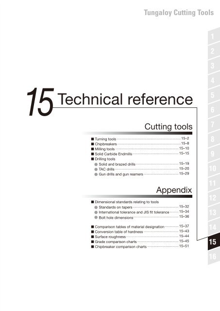
15<br />
Technical reference<br />
Cutting tools<br />
Turning tools ........................................................................................ 15–2<br />
Chipbreakers ....................................................................................... 15–8<br />
Milling tools ....................................................................................... 15–10<br />
Solid Carbide Endmills ............................................................... 15–15<br />
Drilling tools<br />
Solid and brazed drills ........................................................... 15–19<br />
TAC drills ........................................................................................ 15–20<br />
Gun drills and gun reamers ................................................ 15–29<br />
Appendix<br />
Dimensional standards relating to tools<br />
Standards on tapers ............................................................... 15–32<br />
International tolerance and JIS fit tolerance ............ 15–34<br />
Bolt hole dimensions .............................................................. 15–36<br />
Comparison tables of material designation ................... 15–37<br />
Conversion table of hardness ................................................ 15–43<br />
Surface roughness ........................................................................ 15–44<br />
Grade comparison charts ......................................................... 15–45<br />
Chipbreaker comparison charts ........................................... 15–51<br />
1<br />
2<br />
3<br />
4<br />
5<br />
6<br />
7<br />
8<br />
9<br />
10<br />
11<br />
12<br />
13<br />
14<br />
15<br />
16
Technical Reference<br />
Turning Tools<br />
Name of tools parts<br />
Side relief<br />
angle<br />
Side rake<br />
angle<br />
height<br />
Cutting edge<br />
End cutting edge angle<br />
Corner<br />
radius<br />
Cutting edge<br />
inclination<br />
Front relief angle<br />
Side cutting<br />
edge angle<br />
Shank height<br />
Overall length<br />
Shank width<br />
End cutting edge<br />
(Minor cutting edge)<br />
Rake face<br />
End relief face<br />
Corner (Nose)<br />
Indexable<br />
inserts<br />
Side relief<br />
face<br />
Shank<br />
Shim<br />
Side cutting edge<br />
(Major cutting edge)<br />
Relating angles between tool and workpiece<br />
a p<br />
k<br />
Work surface<br />
h<br />
f<br />
a e<br />
Machined surface<br />
ap … Depth of cut (Distance between work surface and machined<br />
surface)<br />
ae … Length of cutting edge engaging in cutting.<br />
κ … Cutting edge angle (Angle to be made by cutting edge and work<br />
surface)<br />
f … Feed per revolution<br />
h … Thickness to be cut per revolution<br />
Machined surface … Workpiece surface after having machined.<br />
Work surface … Workpiece surface to be cut.<br />
Effect of side cutting edge angle<br />
Honing<br />
TAC indexable inserts of steel cutting grades are honed.<br />
Honing specifications are shown in the following table.<br />
Edge condition<br />
Shape<br />
Sharp edge<br />
Round honing<br />
Chamfered honing<br />
Technical Reference<br />
0<br />
15<br />
30<br />
In the cutting of same feed rate, as the side cutting edge angle<br />
increases, the chip thickness decreases.<br />
h0h1h2<br />
Effects of tool geometry on cutting phenomena<br />
Phenomena Flank Crater Edge<br />
Increasing<br />
wear wear strength<br />
Cutting<br />
force<br />
Surface<br />
finish<br />
Chattering<br />
Cutting edge<br />
temperature<br />
Chip shape<br />
and flow<br />
15<br />
Cutting edge inclination<br />
Side rake angle<br />
–<br />
–<br />
Decrease<br />
Decrease<br />
Lower<br />
Lower<br />
Radial force<br />
decrease<br />
Decrease<br />
–<br />
–<br />
Less tendency<br />
–<br />
Lower<br />
Lower<br />
Effect on<br />
flow direction<br />
Effect on<br />
shape<br />
Relief angle<br />
Decrease<br />
–<br />
Lower<br />
Decrease<br />
–<br />
Likely to occur<br />
Lower<br />
–<br />
End cutting edge angle<br />
Decrease<br />
–<br />
Lower<br />
Radial force<br />
decrease<br />
Roughen<br />
Less tendency<br />
Lower<br />
–<br />
Side cutting edge angle<br />
Decrease<br />
Decrease<br />
Increase<br />
Radial force<br />
decrease<br />
–<br />
Likely to occur<br />
Increase<br />
Decrease<br />
thickness<br />
Nose radius<br />
Decrease to some level<br />
Increase<br />
Increase<br />
Improve<br />
Likely to occur<br />
Increase<br />
Effect on<br />
flow direction<br />
Honing width<br />
Increase<br />
–<br />
Increase<br />
Increase<br />
–<br />
Likely to occur<br />
Increase<br />
–<br />
15–2
Technical Reference<br />
Turning Tools<br />
Relations between cutting force and cutting conditions or cutting phenomena<br />
Conditions<br />
Grey cast iron (HB130) Stainless steel (HB145) Carbon steel (HB230)<br />
Cutting speed and<br />
cutting force<br />
f = 0.2 mm/rev<br />
ap = 2 mm<br />
Side cutting edge<br />
angle 0°<br />
Corner radius r ε 0.4<br />
Cutting force (N)<br />
1000<br />
Negative<br />
900<br />
800<br />
Positive<br />
700<br />
600<br />
40 60 80 100 120<br />
Cutting speed: Vc (m/min)<br />
Cutting force (N)<br />
1500<br />
1400<br />
1300<br />
Negative<br />
1200<br />
1100<br />
Positive<br />
40 60 80 100 120<br />
Cutting speed: Vc (m/min)<br />
Cutting force (N)<br />
1400<br />
1300<br />
Negative<br />
1200<br />
1100<br />
Positive<br />
1000<br />
40 60 80 100 120<br />
Cutting speed: Vc (m/min)<br />
Depth of cut and<br />
cutting force<br />
Vc = 100 m/min<br />
f = 0.2 mm/rev<br />
Side cutting edge<br />
angle 0°<br />
Corner radius r ε 0.4<br />
Cutting force (N)<br />
2500<br />
2000<br />
2500<br />
2000<br />
2500<br />
2000<br />
Negative<br />
1500 Negative<br />
1500 Negative<br />
1500<br />
1000<br />
1000<br />
1000<br />
Positive<br />
Positive<br />
Positive<br />
500<br />
500<br />
500<br />
0 1 2 3 4 5<br />
0 1 2 3 4 5<br />
0 1 2 3 4 5<br />
Depth of cut: ap (mm) Depth of cut: ap (mm) Depth of cut: ap (mm)<br />
Cutting force (N)<br />
Cutting force (N)<br />
Feed and cutting force<br />
Vc = 100 m/min<br />
ap = 2 mm<br />
Side cutting edge<br />
angle 0°<br />
Corner radius r ε 0.4<br />
Cutting force (N)<br />
2500<br />
2000<br />
1500<br />
1000<br />
500<br />
0<br />
Negative<br />
Positive<br />
Cutting force (N)<br />
2500<br />
2000<br />
1500<br />
Negative<br />
1000<br />
Positive<br />
500<br />
0.1 0.2 0.3 0.4 0.5<br />
0 0.1 0.2 0.3 0.4 0.5 0 0.1 0.2 0.3 0.4 0.5<br />
Feed: f (mm/rev) Feed: f (mm/rev) Feed: f (mm/rev)<br />
Cutting force (N)<br />
2500<br />
2000<br />
Negative<br />
1500<br />
1000<br />
Positive<br />
500<br />
Corner radius and<br />
cutting force<br />
Vc = 100 m/min<br />
f = 0.2 mm/rev<br />
ap = 1.2 mm<br />
Side cutting edge<br />
angle 0°<br />
Side cutting edge angle<br />
and cutting force<br />
Vc = 100 m/min<br />
f = 0.2 mm/rev<br />
ap = 2 mm<br />
Corner radius r ε 0.4<br />
Side rake angle and<br />
cutting force<br />
Vc = 100 m/min<br />
f = 0.2 mm/rev<br />
ap = 2 mm<br />
Side cutting edge<br />
angle 0°<br />
Corner radius r ε 0.2<br />
* 9.8N = 1kgf<br />
Cutting force (N)<br />
Cutting force (N)<br />
Cutting force (N)<br />
1000<br />
800 Negative<br />
600<br />
Positive<br />
400<br />
200<br />
Cutting force (N)<br />
1000<br />
Negative<br />
800<br />
Positive<br />
600<br />
400<br />
200<br />
0 0.4 0.8 1.2 1.6 2.0<br />
0 0.4 0.8 1.2 1.6 2.0<br />
0 0.4 0.8 1.2 1.6 2.0<br />
Corner radius: rε (mm)<br />
Corner radius: r ε (mm)<br />
Corner radius: r ε (mm)<br />
1200<br />
1100<br />
Negative<br />
1000<br />
900<br />
800<br />
Positive<br />
Cutting force (N)<br />
1400<br />
1300<br />
Negative<br />
1200<br />
1100<br />
Positive<br />
1000<br />
45° 30° 15° 0°<br />
45° 30° 15° 0°<br />
45° 30° 15° 0°<br />
Side cutting edge angle<br />
Side cutting edge angle<br />
Side cutting edge angle<br />
1200 1400 1400<br />
1000<br />
800<br />
600<br />
1200<br />
1000<br />
800<br />
600<br />
1200<br />
1000<br />
800<br />
600<br />
−10° 0° 15°<br />
−10° 0° 15°<br />
−10° 0° 15°<br />
Side rake angle Side rake angle Side rake angle<br />
Cutting force (N)<br />
Cutting force (N)<br />
Cutting force (N)<br />
Cutting force (N)<br />
1000<br />
Negative<br />
800<br />
600<br />
Positive<br />
400<br />
200<br />
1400<br />
Negative<br />
1300<br />
1200<br />
1100 Positive<br />
1000<br />
Technical Reference<br />
15<br />
15–3
Technical Reference<br />
Turning Tools<br />
Calculation formulas for turning<br />
Cutting speed<br />
Turning<br />
øDm<br />
n<br />
When calculating cutting speed from number of revolutions:<br />
(m/min)<br />
Vc : Cutting speed (m/min)<br />
n : Number of revolution (min<br />
- 1 )<br />
Dm : Diameter of work piece (mm)<br />
π ≈ 3.14<br />
Boring<br />
øDm<br />
n<br />
When calculating required number<br />
of revolutions from cutting speed:<br />
n<br />
(min -1 )<br />
Example : Calculating the cutting<br />
speed when turning a 150 mmdiameter<br />
workpiece at 250 min -1<br />
3.14 × 150 × 250<br />
Vc =<br />
= 117 m/min<br />
1000<br />
Cutting time on external and internal turning<br />
External<br />
turning<br />
R<br />
T<br />
(min)<br />
R<br />
f n<br />
T : Cutting time (min)<br />
R : Cutting length (mm)<br />
f : Feed (mm/rev)<br />
n : Number of revolution (min -1 )<br />
Internal<br />
turning<br />
R<br />
Cutting time on face turning<br />
T<br />
(min)<br />
Vc : Cutting speed (m/min)<br />
f : Feed (mm/rev)<br />
T : Cutting Time (min)<br />
Technical Reference<br />
Theoretical surface finish<br />
f<br />
15<br />
(µm)<br />
h<br />
h : Surface finish (µm)<br />
f : Feed (mm/rev)<br />
r ε : Nose radius (mm)<br />
r ε<br />
Calculation of power consumption (kW)<br />
Pc : Power requirement (kW)<br />
F : Cutting force (N)<br />
V c : Cutting speed (m/min)<br />
15–4
Technical Reference<br />
Turning Tools<br />
Cutting forces<br />
(1) Finding from the diagram based on experimental data.<br />
(2) In case determining by simplified equation:<br />
Cutting force in turning<br />
Feed force<br />
Principal force<br />
Back force<br />
Resultant cutting force<br />
F : Cutting force (N)<br />
kc : Specific cutting force (N/mm 2 )<br />
[Refer to the Table below]<br />
ap : Depth of cut (mm)<br />
f : Feed (mm/rev)<br />
Example :<br />
Calculating the cutting force when<br />
cutting a high carbon steel (JIS S55C)<br />
at 0.2mm/rev feed and<br />
3mm depth of cut.<br />
F=343030.2=2058N<br />
Calculating power requirement<br />
c<br />
Pc : Net power requirement (kW)<br />
kc : Specific cutting force (N/mm 2 )<br />
[Refer to the Table below]<br />
vc : Cutting speed (m/min)<br />
ap : Depth of cutting (mm)<br />
f : Feed (mm/rev)<br />
Value of specific cutting force (kc)<br />
Work material<br />
SS400, S15C<br />
S35C, S40C<br />
S50C, SCr430<br />
SCM440, SNCM439<br />
SDK<br />
FC200<br />
FCD600<br />
Aluminium alloy<br />
Aluminium<br />
Magnesium alloy<br />
Brass<br />
Tensile strength (Mpa)<br />
390<br />
590<br />
785<br />
980<br />
1765 ( 56HRC )<br />
( 160HB )<br />
( 200HB )<br />
( 89HB )<br />
Hardness (HB)<br />
100<br />
170<br />
230<br />
300<br />
56HRC<br />
160<br />
200<br />
89<br />
Value of specific cutting force on feed kc (N/mm 2 )<br />
0.04 (mm/rev) 0.1 (mm/rev) 0.2 (mm/rev) 0.4 (mm/rev) 1.0 (mm/rev)<br />
3430<br />
4220<br />
4900<br />
5390<br />
8390<br />
2550<br />
3330<br />
1350<br />
1050<br />
390<br />
1080<br />
2840<br />
3490<br />
4020<br />
4410<br />
6870<br />
1960<br />
2550<br />
1130<br />
870<br />
390<br />
1080<br />
2450<br />
2940<br />
3430<br />
3780<br />
5880<br />
1630<br />
2110<br />
950<br />
740<br />
390<br />
1080<br />
2080<br />
2500<br />
2940<br />
3240<br />
5000<br />
1340<br />
1750<br />
810<br />
640<br />
390<br />
1080<br />
1700<br />
2080<br />
2400<br />
2650<br />
4120<br />
1030<br />
1340<br />
670<br />
520<br />
390<br />
1080<br />
Bending stress and tool deflection<br />
Square shank<br />
Round shank<br />
Bending stress<br />
(1) Square shank<br />
( MPa )<br />
(2) Round shank<br />
( MPa )<br />
Tool defection (mm)<br />
(1) Square shank<br />
S : Bending stress in shank (MPa)<br />
F : Cutting force (N)<br />
L : Overhang length of tool (mm)<br />
b : Shank width (mm)<br />
h : Shank height (mm)<br />
Ds : Shank diameter (mm)<br />
E : Modulus of elasticity of shank<br />
material (MPa)<br />
Technical Reference<br />
15<br />
øDs<br />
( mm )<br />
(2) Round shank<br />
(Ref.) Values of E<br />
Material MPa (N/mm 2 ) {kgf/mm 2 }<br />
( mm )<br />
Steel 210,000 21,000<br />
Cemented<br />
Carbide<br />
560,000~620,000 56,000~62,000<br />
15–5
Technical Reference<br />
Turning Tools<br />
Troubleshooting in turning<br />
Flaking Chipping Fracture Notch wear Crater wear Flank wear<br />
Typical tool failure<br />
Countermeasures<br />
Tool grade Cutting conditions Tool geometry<br />
• Change to more wear resistant • Reduce cutting speed. • Decrease honing width.<br />
grades.<br />
• Change to appropriate feed.<br />
• Increase relief angle.<br />
• Increase end cutting edge angle.<br />
• Change to wet cutting.<br />
P, M, K30 / 20 / 10<br />
• Increase corner radius.<br />
• Select free-cutting chipbreaker.<br />
• Increase rake angle.<br />
• Change to more wear resistant<br />
grades.<br />
P, M, K30 / 20 / 10<br />
• Change to more wear resistant<br />
grades.<br />
P, M, K30 / 20 / 10<br />
• Change to tougher grades.<br />
• Change to thermal-shock resistant<br />
grades.<br />
P, M, K10 / 20 / 30<br />
• Change to tougher grades.<br />
P, M, K10 / 20 / 30<br />
• Change to tougher grades.<br />
P, M, K10 / 20 / 30<br />
• Reduce cutting speed.<br />
• Reduce feed.<br />
• Reduce depth of cut.<br />
• Change to wet cutting.<br />
• Reduce cutting speed.<br />
• Reduce feed.<br />
• Reduce feed.<br />
• Reduce depth of cut<br />
• Improve holding rigidity of<br />
work and tool.<br />
• Reduce overhang length of<br />
toolholder.<br />
• Improve looseness in<br />
machine.<br />
• Reduce cutting speed<br />
• Reduce feed.<br />
• Reduce depth of cut.<br />
• Improve holding rigidity of<br />
work and tool.<br />
• Reduce overhang length of<br />
toolholder.<br />
• Improve looseness in<br />
machine.<br />
• Reduce cutting speed<br />
• Reduce feed.<br />
• Increase rake angle.<br />
• Select an appropriate chipbreaker.<br />
• Increase side cutting edge angle.<br />
• Increase corner radius.<br />
• Increase rake angle.<br />
• Increase side cutting edge angle.<br />
• Reduce rake angle<br />
• Select a chipbreaker with high edge strength.<br />
• Increase honing width.<br />
• Increase side cutting edge angle.<br />
• Select larger shank size<br />
• Increase corner radius.<br />
• Reduce rake angle<br />
• Select a chipbreaker with high edge<br />
strength.<br />
• Increase honing width.<br />
• Increase side cutting edge angle.<br />
• Select larger shank size<br />
• Reduce rake angle<br />
• Increase corner radius<br />
• Increase honing width.<br />
Technical Reference<br />
15<br />
Plastic deformation<br />
Chip welding<br />
Thermal cracking Built-up edge<br />
• Change to more wear resistant<br />
grade.<br />
P, M, K30 / 20 / 10<br />
• Reduce cutting speed.<br />
• Change to appropriate feed.<br />
• Reduce depth of cut.<br />
• Supply cutting fluid in<br />
adequate volume.<br />
• Use a grade which has a low • Increase cutting speed.<br />
tendency to adhere to work material. • Increase feed<br />
• Change to water-insoluble<br />
Cemented carbide /<br />
cutting fluid.<br />
Coated carbide or cermet<br />
• Change to wet cutting.<br />
• Change to tougher grades.<br />
• Change to thermal-shock resistant<br />
grades.<br />
P, M, K10/20/30<br />
• Reduce cutting speed.<br />
• Reduce feed.<br />
• Change to dry cutting.<br />
• Supply cutting fluid in<br />
adequate volume.<br />
• Reduce depth of cut.<br />
• Change to water-insoluble<br />
cutting fluid.<br />
• Increase relief angle.<br />
• Increase rake angle.<br />
• Reduce corner radius.<br />
• Reduce side cutting edge angle.<br />
• Select a free-cutting chipbreaker.<br />
• Increase rake angle<br />
• Select a free-cutting chipbreaker.<br />
• Decrease honing width.<br />
• Increase rake angle<br />
• Select a free-cutting chipbreaker.<br />
• Decrease honing width.<br />
15–6
Technical Reference<br />
Turning Tools<br />
Problem<br />
Cause<br />
• Increased tool wear<br />
Tool<br />
• Select a more wear resistant grade.<br />
• Use an insert with a larger rake angle.<br />
• Use an insert with a larger nose radius.<br />
• Use a more lightly honed insert.<br />
• Use an insert of closer tolerance. (from M class to G class)<br />
Countermeasures<br />
Cutting conditions and others<br />
• Select a proper feed rate.<br />
• Decrease the cutting speed.<br />
• Select a freer-cutting chipbreaker type.<br />
• Use a cutting fluid.<br />
Deteriorated surface roughness<br />
• Edge chipping<br />
• Chip welding<br />
• Built-up-edge<br />
• Vibration and chatter<br />
• Use a tougher grade.<br />
• Select a chipbreaker with strong cutting edges.<br />
• Use a largely honed insert.<br />
• Increase the side cutting edge angle.<br />
• Use a larger shank size.<br />
• Select a grade with less affinity with the work material.<br />
• Use an insert with a larger rake angle.<br />
• Select a freer-cutting chipbreaker type.<br />
• Use a more lightly honed insert.<br />
• Use an insert of closer tolerance. (from M class to G class)<br />
• Use a tougher grade.<br />
• Use an insert with a larger rake angle.<br />
• Select a freer-cutting chipbreaker type.<br />
• Use an insert with a smaller nose radius.<br />
• Decrease the side cutting edge angle.<br />
• Use a more lightly honed insert.<br />
• Use a larger shank size.<br />
• Decrease the depth of cut.<br />
• Decrease the feed rate.<br />
• Use a more rigid machine.<br />
• Improve the holding rigidity of the tool and workpiece.<br />
• Shorten the overhang of the toolholder.<br />
• Improve the machine looseness.<br />
• Increase the cutting speed.<br />
• Increase the feed rate.<br />
• Use a water-insoluble cutting fluid.<br />
• Use a cutting fluid.<br />
• Use a proper cutting speed.<br />
• Decrease the feed rate.<br />
• Decrease the depth of cut.<br />
• Improve the holding rigidity of the tool and workpiece.<br />
• Shorten the overhang of the toolholder.<br />
• Improve the machine looseness.<br />
Deteriorated<br />
dimensional<br />
accuracy<br />
• Improper insert accuracy<br />
• Incomplete engagement of<br />
tool and workpiece<br />
• Use an insert of closer tolerance.<br />
(from M class to G class)<br />
• Use an insert with a larger rake angle.<br />
• Select a freer-cutting chipbreaker type.<br />
• Use an insert with a smaller nose radius.<br />
• Use a more lightly honed insert.<br />
• Improve the holding rigidity of the tool and workpiece.<br />
• Shorten the overhang of the toolholder.<br />
• Improve the machine looseness.<br />
Burr occurrence<br />
Edge breakout<br />
• Unsuitable cutting speed<br />
• Worn tool or improper<br />
cutting edge geometry<br />
• Improper cutting speed<br />
• Worn tool or improper<br />
cutting edge geometry<br />
• Use a harder grade.<br />
• Use an insert with a larger rake angle.<br />
• Select a freer-cutting chipbreaker type.<br />
• Increase the relief angle.<br />
• Use an insert with a smaller nose radius.<br />
• Decrease the side cutting edge angle.<br />
• Use a more lightly honed insert.<br />
• Use a harder grade.<br />
• Use an insert with a larger rake angle.<br />
• Select a freer-cutting chipbreaker type.<br />
• Increase the side cutting edge angle.<br />
• Use an insert with a larger nose radius.<br />
• Use a more lightly honed insert.<br />
• Use a larger shank size.<br />
• Decrease the cutting speed.<br />
• Increase the feed rate.<br />
• Use a cutting fluid.<br />
• Decrease the feed rate.<br />
• Decrease the depth of cut.<br />
• Improve the holding rigidity of the tool and workpiece.<br />
• Shorten the overhang of the toolholder.<br />
• Improve the machine looseness.<br />
Technical Reference<br />
15<br />
Fuzzy surface finish<br />
• Improper cutting<br />
conditions<br />
• Worn tool or improper<br />
cutting edge geometry<br />
• Use a harder grade.<br />
• Select a grade with less affinity with the work material.<br />
• Use an insert with a larger rake angle.<br />
• Select a freer-cutting chipbreaker type.<br />
• Use a more lightly honed insert.<br />
• Increase the cutting speed.<br />
• Select a proper feed rate.<br />
• Use a water-insoluble cutting fluid.<br />
• Use a cutting fluid.<br />
15–7
Technical Reference<br />
Chipbreaker<br />
Chip controllability<br />
Necessity of chip control<br />
Why is chip control needed?<br />
Effect of improper chip control<br />
Necessity of chip control (Problems and effects)<br />
Problems<br />
Effects<br />
1. Scattering of chips and 1. Disturbs unmanned and automated machining.<br />
coolant.<br />
2. Disturbs high-speed and high-efficiency machining.<br />
2. Wrapping around the 3. Degrades finished surface.<br />
workpiece and the tool.<br />
3. Accumulation on the tool, jig, 4. Threatens operator’s safety.<br />
and machining facilities. 5. Reduced operation rate.<br />
Additional problems when<br />
chips are not properly<br />
controlled<br />
Why is chip control needed?<br />
What is chip?<br />
Effect of improper chip control<br />
Effects on quality<br />
• Defective work.<br />
• Defective surface finish<br />
• Chip entangling<br />
For making a product from a workpiece, removed<br />
objects produced by a tool which is set to cut to a<br />
specified depth with the relative motion of the tool<br />
and the workpiece.<br />
Problems when chips<br />
are not properly<br />
controlled<br />
Effects on operation<br />
Effect on safety<br />
and health.<br />
Effective measures<br />
• Increased number of man-hours for handling.<br />
• Increased tool costs.<br />
• Troublesome chip handling.<br />
• Machine stoppage and reduced operation rate.<br />
• Stain and damage on machine caused<br />
from improper carrying-out of chips.<br />
• Dangerous effects on the human body.<br />
(Injury and burns on hand, etc.)<br />
“Chipbreaker”<br />
Classification<br />
Depth of cut: small<br />
Chip shape<br />
Depth of cut: large<br />
Description of<br />
chip shape<br />
Acceptability<br />
Effect<br />
Shape A<br />
Chips irregularly<br />
entangled<br />
Not acceptable<br />
• Wrapping around the tool or workpiece or<br />
accumulation around the cutting point,<br />
hindering cutting<br />
• Possible damage to the machined surface<br />
Technical Reference<br />
15<br />
Shape B<br />
Shape C<br />
Shape D<br />
Long continuous<br />
spiral chips<br />
R 50 mm<br />
Short spiral chips<br />
R 50 mm<br />
"C" or "9" shaped<br />
chips (Around one<br />
coiling)<br />
Acceptable<br />
• Bulky during transport in the automatic<br />
line<br />
• May be preferred when one operator<br />
handles one machine<br />
• Smooth chip flow<br />
• Difficult to scatter<br />
• Favorable shape<br />
• Favorable shape if not scattering<br />
• Not bulky and easy to transport<br />
Shape E<br />
Excessively broken<br />
chips. Thin pieces or<br />
connected in a form<br />
of wave as shown in<br />
the figure left<br />
Not acceptable<br />
• Readily scattering. If scattering is the only<br />
trouble, it may be acceptable because the<br />
chip cover, etc. may be used.<br />
• Tend to cause chatter, causing harm on the<br />
finished surface roughness or tool life.<br />
15–8
Technical Reference<br />
Chipbreaker<br />
Factors affecting chip control<br />
(1) Cutting conditions<br />
1 Feed<br />
2 Depth of cut<br />
3 Cutting speed<br />
• Of these, feed has the greatest effect<br />
followed by depth of cut and cutting speed<br />
in order listed.<br />
• Feed is proportionate to the thickness of<br />
chips.<br />
• Depth of cut is proportionate to the width of<br />
chips.<br />
• There are optimum values (effective range) in<br />
feed and depth of cut.<br />
• Cutting speed is in inverse proportion to chip<br />
thickness. Effective range becomes narrow<br />
at high speed.<br />
Depth of cut: ap (mm)<br />
Vc = 100 m/min<br />
Effecttive<br />
range<br />
Feed: f (mm/rev)<br />
Vc = 200 m/min<br />
(2) Work material<br />
1 Alloy element<br />
2 Hardness<br />
3 Heat treatment<br />
condition<br />
• These are related to thickness of chips<br />
and ease of curling.<br />
• Mild steel chips are thicker than those of<br />
hard steel.<br />
• Hard steel chips are liable to curl more<br />
than those of mild steel.<br />
• Chips that do not curl are thin. As an<br />
exception, in case of mild steel even if<br />
thick, may not curl.<br />
Depth of cut: ap (mm)<br />
Mild steel<br />
Hard steel<br />
Feed: f (mm/rev)<br />
(3) Tool geometry<br />
1 Side cutting<br />
edge angle<br />
2 Nose radius<br />
• Side cutting edge angle is relative to chip<br />
thickness and width<br />
• Side cutting edge angle is preferably<br />
small.<br />
• Nose radius is relative to thickness and<br />
width and the direction of flowing out.<br />
• In finishing, small nose radius, whilst for<br />
rough cutting, large nose radius is better.<br />
Depth of cut: ap (mm)<br />
S.C.E.A: small<br />
Nose radius: small<br />
S.C.E.A: large<br />
Nose radius: large<br />
Feed: f (mm/rev)<br />
(4) Shape of chipbreaker<br />
1 Rake angle<br />
2 Chipbreaker width<br />
3 Chipbreaker depth<br />
(5) Cutting fluid<br />
• Rake angle is in inverse proportion to chip<br />
thickness.<br />
• Depending on the work material, there is<br />
an optimum value.<br />
• Chipbreaker width is selected<br />
proportionately to feed.<br />
• Narrow at low feed and wide at high feed.<br />
• Chipbreaker depth is to be selected so as<br />
to be inversely proportionate to feed.<br />
• Deep at low feed and shallow at high feed.<br />
• Effective range is wider with wet cutting.<br />
• Especially at low feed range is liable to<br />
curl.<br />
Depth of cut: ap (mm)<br />
Depth of cut: ap (mm)<br />
Rake angle: small<br />
Breaker width: small<br />
Breaker depth: large<br />
Wet cutting<br />
Rake angle: large<br />
Breaker width: large<br />
Breaker depth: small<br />
Feed: f (mm/rev)<br />
Dry cutting<br />
Technical Reference<br />
15<br />
Feed: f (mm/rev)<br />
(6) Machine<br />
1 Strength<br />
2 Power limit<br />
• The machine has enough power and<br />
mechanical strength.<br />
• Select the machine consistent with the<br />
size of work material to be used.<br />
15–9
Technical Reference<br />
Milling Tools<br />
Nomenclature for face milling cutter<br />
Peripheral cutting edge<br />
(Main cutting edge)<br />
Axial rake angle (γp) (“A.R.” on catalogue.)<br />
Inserts<br />
Chamfering<br />
corner<br />
Cutting edge inclination (λ)<br />
Cutter height<br />
Work piece<br />
Face cutting edge<br />
(Wiping flat)<br />
Face relief<br />
angle<br />
Peripheral<br />
cutting<br />
edge angle<br />
(κ)<br />
Mounting<br />
hole dia. (ød)<br />
True rake<br />
angle (γ0)<br />
Peripheral<br />
relief angle<br />
Effective cutter dia. (øDc)<br />
Radial rake angle (γf) (“R.R.” on catalogue.)<br />
• Relations of various rake angles are<br />
according to the following equations.<br />
tan γ 0 = tan γ f cos κ + tan γ p sin κ<br />
tan λ = tan γ p cos κ - tan γ f sin κ<br />
Cutter geometry and applications<br />
Technical Reference<br />
15<br />
Shapes<br />
of cutting<br />
edge<br />
Work<br />
material<br />
Rake angle combination and applicability<br />
Negative-Negative Negative-Positive Positive-Positive<br />
γp (A.R)<br />
- + +<br />
γf<br />
γo<br />
(R.R)<br />
-<br />
-<br />
-<br />
+<br />
+<br />
+<br />
Carbon steels,<br />
Alloy steels ( 300HB)<br />
Stainless steels ( 300HB)<br />
Die steels ( 300HB)<br />
Cast irons Ductile cast irons<br />
Aluminium alloys<br />
Copper and its alloys<br />
Titanium and its alloys<br />
Hardened steels<br />
(40 ~ 55HRC)<br />
<br />
×<br />
<br />
<br />
×<br />
×<br />
×<br />
<br />
<br />
<br />
<br />
<br />
<br />
<br />
<br />
<br />
<br />
<br />
<br />
<br />
<br />
<br />
<br />
×<br />
(-) Axial rake angle<br />
Radial rake angle<br />
(-)<br />
Negative type<br />
(Negative-Negative)<br />
Rake angle combination<br />
(+) Axial rake angle<br />
Radial rake angle<br />
(-)<br />
Negative-Positive type<br />
(+) Axial rake angle<br />
Radial rake angle<br />
(+)<br />
Positive type<br />
(Positive-Positive)<br />
Features<br />
· Higher<br />
cutting edge<br />
strength<br />
· Many usable<br />
corners of<br />
inserts<br />
· Excellent chip · Most<br />
removal excellent<br />
· Higher cutting cutting action<br />
edge strength<br />
and Freer<br />
cutting action<br />
Typical examples of TAC mills<br />
TGN4200<br />
TAW13<br />
TME4400<br />
TMD4400<br />
THF4000<br />
THE4000<br />
15–10
Technical Reference<br />
Milling Tools<br />
Calculation formulas for milling<br />
Cutting speed<br />
n<br />
Cutting speed (Calculated from number of revolutions)<br />
vc : Cutting speed (m/min)<br />
Dc : Effective diameter (mm)<br />
n : Number of revolutions (min -1 )<br />
π ≈ 3.14<br />
Number of revolution (Calculated from cutting speed)<br />
ap<br />
ae<br />
v f<br />
Rp<br />
fz (Feed per tooth)<br />
f (Feed per revolution)<br />
Feed speed and feed rate<br />
vf : Table feed (mm/min)<br />
fz : Feed rate per tooth (mm/t)<br />
z : No. of teeth of the cutter<br />
n : Number of revolutions (min -1 )<br />
Feed speed is relative speed of cutter and work material and in the<br />
normal milling machine, it is the table speed.<br />
In milling, the feed per tooth is very important. The recommended cutting<br />
condition is expressed by vc and fz and using the above equation<br />
calculate n and vf and input in the machine.<br />
Cutting time on face milling<br />
T : Cutting time (min)<br />
L : Total table feed length.<br />
(R: Work pieces length (mm) + øDc:<br />
Effective cutter diameter (mm))<br />
vf : Table feed (mm/min)<br />
Depth of cut and cutting width<br />
Depth of cut<br />
Determine by required allowance for machining and capacity of the<br />
machine. In case of TAC mill, there are cutting limits according to<br />
shape and size of the insert. Please see spec on the catalogue.<br />
ap : Depth of cutting (mm)<br />
Technical Reference<br />
Center<br />
cutting<br />
Shoulder<br />
cutting<br />
E<br />
v c<br />
v c<br />
øDc<br />
ae<br />
ae<br />
Cutting width and engagement angle<br />
There is an appropriate engage angle depending on the cutter diameter,<br />
cutting position, work material, etc., and ordinarily the values in the<br />
table below are used as a guide.<br />
Work material Appropriate E Cutter dia. and ae<br />
Steel<br />
0°~ 20°<br />
(on small side for<br />
shoulder cutting)<br />
2<br />
a e ≈ Dc<br />
3<br />
Dc : Cutter diameter (mm)<br />
E : Engage angle<br />
ae : Cutting width (mm)<br />
15<br />
E<br />
øDc<br />
Cast iron<br />
under 40°<br />
4<br />
a e ≈ Dc<br />
5<br />
15–11
ε<br />
Technical Reference<br />
Milling Tools<br />
Roughness of finished surface<br />
(1) Theoretical surface roughness<br />
Theoretical roughness as shown in Fig. 1, is the same as for single point turning<br />
With corner R<br />
r <br />
Without corner R<br />
<br />
<br />
<br />
<br />
Rth: Theoretical roughness (µm)<br />
fz: Feed per tooth (mm/t)<br />
r ε: Corner radius (mm)<br />
α : Corner angle<br />
β : Face cutting edge angle<br />
With corner R<br />
Without corner R<br />
Rth<br />
Rth<br />
α<br />
β<br />
Fig.1<br />
fz<br />
fz<br />
Rp<br />
Fig.2<br />
fz (Feed per tooth)<br />
f (Feed per revolution)<br />
(2) Practical surface roughness<br />
In case of practical milling, there are many teeth and natural differences in<br />
levels of edges occur. The maximum difference is called “run out”. (Rp)<br />
In the actual face milling, finished surface roughness, as shown in Fig. 2, is<br />
worse than the single point cutting. If only one tooth is projecting, it will be<br />
similar to the single point shown in Fig. 1 but of a large value substituting<br />
f (mm/rev) for fz (mm/t).<br />
Improving surface roughness<br />
Technical Reference<br />
Fig.3<br />
Body<br />
Insert<br />
SPCN42ZFR<br />
Locator<br />
0.03 ~ 0.08<br />
Face run out must be minimized and a low feed rate and high speed should<br />
be used. Also, in order to attain good finished surface at high efficiency,<br />
there are the following methods:<br />
(1) In case of ordinary TAC mill<br />
Use wiper insert as shown in the figure at left.<br />
(2) Use of TAC super finish mill for finishing.<br />
• Use of combination TAC mills with finishing insert such as TFD4400-A<br />
and TFP40001A (ap < 1.0 mm).<br />
• Use of TAC supe finish mill for finishing such as NMS cutters and<br />
SFP4000, etc.<br />
15<br />
15–12
Technical Reference<br />
Milling Tools<br />
Calculating power requirement<br />
Pc : Net power requirement (kW)<br />
kc : Specific cutting force (N/mm 2 )<br />
[Refer to the Table below]<br />
ap : Depth of cut (mm)<br />
Because practical power requirements depend on the type of TAC mill<br />
ae : Cutting width (mm)<br />
(proportional to the true rake angle) and the motor effi ciency of the<br />
vf : Table feed (mm/min)<br />
machine used, the result calculated from the above formula should be<br />
considered as a rough guide.<br />
Values of specific cutting force (kc)<br />
Work material<br />
Tensile strength Value of specific cutting force on feed per tooth kc (N/mm 2 )<br />
MPa 0.1 (mm/t) 0.15 (mm/t) 0.2 (mm/t) 0.3 (mm/t) 0.4 (mm/t)<br />
SS400 520 2150 2000 1900 1750 1650<br />
S55C 770 1970 1860 1800 1760 1620<br />
SCM3 730 2450 2350 2200 1980 1710<br />
SKT4 (HB352) 2030 2010 1810 1680 1590<br />
SC450 520 2710 2530 2410 2240 2120<br />
FC250 (HB200) 1660 1450 1320 1150 1030<br />
AR(Si) 200 660 580 522 460 410<br />
Brass<br />
500 1090 960 877 760 680<br />
Values of cutting force (kc)<br />
1800<br />
1600<br />
1400<br />
Principal force fy<br />
Feed force fx<br />
Back force fz<br />
1200<br />
Cutting force (N)<br />
1000<br />
800<br />
600<br />
400<br />
200<br />
0<br />
-200<br />
TGP4100<br />
TGP4200<br />
TGD4400<br />
THF4400<br />
TSP4000<br />
TSE4000<br />
TGN4200<br />
TRD6000<br />
TAC mill<br />
Work material : S50C (210HB) Diameter of TAC mill : ø160 mm<br />
Cutting Speed : Vc = 150 m/min , feed fz = 0.20 mm, Depth of cut ap = 3 mm<br />
Cutting by a single edge, dry<br />
Conversion from cutting speed to number of revolutions (unit : min -1 )<br />
Cutter diameter<br />
Cutting speed ( v c ) m/min<br />
øDc ( mm ) 10 30 50 100 125 150 200 300 500 800 1,000 2,000 4,000<br />
10 318 955 1,592 3,184 3,980 4,777 6,369 9,554 15,923 25,477 31,847 63,694 127,388<br />
12 265 796 1,326 2,653 3,317 3,980 5,307 7,961 13,269 21,231 26,539 53,078 106,157<br />
16 199 597 995 1,990 2,488 2,985 3,980 5,971 9,952 15,923 19,904 39,808 79,617<br />
20 159 477 796 1,592 1,990 2,388 3,184 4,777 7,961 12,738 15,923 31,847 63,694<br />
25 127 382 636 1,273 1,592 1,910 2,547 3,821 6,369 10,191 12,738 25,477 50,955<br />
30 106 318 530 1,061 1,326 1,592 2,123 3,184 5,307 8,492 10,615 21,231 42,462<br />
32 99 298 497 995 1,244 1,492 1,990 2,985 4,976 7,961 9,952 19,904 39,808<br />
35 90 272 454 909 1,137 1,364 1,819 2,729 4,549 7,279 9,099 18,198 36,396<br />
40 79 238 398 796 995 1,194 1,592 2,388 3,980 6,369 7,961 15,923 31,847<br />
50 63 191 318 636 796 955 1,273 1,910 3,184 5,095 6,369 12,738 25,477<br />
63 50 151 252 505 631 758 1,011 1,516 2,527 4,044 5,055 10,110 20,220<br />
80 39 119 199 398 497 597 796 1,194 1,990 3,184 3,980 7,961 15,923<br />
100 31 95 159 318 398 477 636 955 1,592 2,547 3,184 6,369 12,738<br />
125 25 76 127 254 318 382 509 764 1,273 2,038 2,547 5,095 10,191<br />
160 19 59 99 199 248 298 398 597 995 1,592 1,990 3,980 7,961<br />
200 15 47 79 159 199 238 318 477 796 1,273 1,592 3,184 6,369<br />
250 12 38 63 127 159 191 254 382 636 1,019 1,273 2,547 5,095<br />
315 10 30 50 101 126 151 202 303 505 808 1,011 2,022 4,044<br />
Note: In this table, the effects of centrifugal force on the rotating balance of the tool and the toolholder, flying risk of cutter parts, and limited value of toolholder<br />
destruction are not considered. Therefore, when using the tool at high speeds, be sure to observe the specified condition range.<br />
fx<br />
v f<br />
fz<br />
fy<br />
Technical Reference<br />
15<br />
15–13
Technical Reference<br />
Milling Tools<br />
Trouble shooting in face milling<br />
Technical Reference<br />
15<br />
Trouble Possible causes Countermeasures<br />
Rapid wear of<br />
cutting edge<br />
Rapid chipping of<br />
cutting edge<br />
Fracturing<br />
Excessive chip<br />
welding or build-up<br />
on cutting edge<br />
Rough finish<br />
Chattering<br />
• Improper insert grade selection<br />
(Insufficient wear resistance)<br />
• Excessive cutting speed<br />
• Inadequate feed<br />
• P30 (Cemented carbide) / Cermet, coated grade (For steels)<br />
• K10 (Cemented carbide) / Coated grade (For cast irons)<br />
• Select cutting speed suited for work material and insert grade<br />
• Use standard cutting condition in catalog as guide<br />
• Improper Insert grade selection (Insufficient toughness) • Cermet / P30 (For steels), K10 / K20 (For cast irons)<br />
• Cutting hard material and<br />
unfavorable surface condition<br />
• Excessive feed<br />
• Decrease cutting speed<br />
• Use cutter with strong cutting edge<br />
• Proper selection of feed conditions, using recommended cutting conditions in catalog as guide<br />
• Excessive pressure applied on cutting edge • Proper selection of engaging angle<br />
• Machining superalloys<br />
• Cracking due to thermal shock<br />
• Continuous use of excessively worn insert<br />
• Cutting hard material<br />
• Obstruction to chip flow<br />
• Recutting of chips after chip welding<br />
• Excessively slow cutting, too fine feed<br />
• Cutting soft material such as aluminium, copper, mild steel<br />
• Cutting stainless steel<br />
• Use of cutter with negative rake<br />
or too small rake angle<br />
• Effect of built-up edge<br />
• Effect of face cutting edge run out<br />
• Continuous use of excessively worn insert<br />
• Remarkable feed marks<br />
• Unstable clamping of workpiece<br />
• Cutting of welded construction of<br />
thin steel plate<br />
• Excessive cutting condition<br />
• Face milling of narrow width workpiece<br />
• Too many simultaneous cutting teeth engagement<br />
• Use a negative-positive type cutter with large corner angle<br />
(Examples: T/EAW13, T/EME4400, etc.)<br />
• Select insert grade of stronger thermal shock resistance such as T3130<br />
• Decrease cutting speed<br />
• Shorten replacement standard time of insert<br />
• Use cutter with stronger cutting edge such as T/ERD6000<br />
• Use cutter of larger corner angle such as<br />
T/EAW13, T/EME4400, etc.<br />
• Use cutter with better chip expulsion such as T/EAW13, etc.<br />
• Select insert grades difficult for chips to adhere<br />
Cemented carbides / cermets, coated grades<br />
• Use air blow<br />
• Select cutting speed and feed optimized for insert grade and<br />
work material<br />
• Use cutter with large rake angle such as T/EAW13<br />
• P30 / coated grades (AH140, AH120)<br />
• Use cutter with large rake angle such as T/EAW13, T/EME4400,<br />
T/EPW13 or T/ESE4000<br />
• Increase cutting speed<br />
• Appropriate cutting depth (finish allowance)<br />
• Change insert grade For steels: P / coated / cermet<br />
For cast irons: K / coated<br />
• Proper installing of inserts<br />
• Use insert of high dimensional accuracy<br />
• Cleaning of insert pocket<br />
• Shorten replacement standard time of insert<br />
• Feed per revolution to be set within flatland width<br />
• Use wiper insert type cutter such as T/EAW13<br />
• Use cutter exclusively for finishing such as type NMS and S/EFP4000<br />
• Check clamping method of workpiece<br />
• Adopt cutter of large rake angle and small corner angle such as<br />
T/EPW13 or T/ESE4000<br />
• Re-examine allowable chip removal rate according to motor HP<br />
• Use cutter of small cutter diameter and with many teeth<br />
• Reduce No. of teeth or adopt irregular pitch cutter<br />
15–14
Technical Reference<br />
Solid Carbide Endmills<br />
Part details<br />
Types<br />
Neck<br />
Shank<br />
Square<br />
Outside diameter<br />
Neck length<br />
Flute length<br />
Shank length<br />
Shank diameter<br />
Centre hole<br />
øDc<br />
Ball nose<br />
øDc<br />
Overall length<br />
Radius<br />
Land width<br />
Flute<br />
Radial rake<br />
1st radial relief<br />
2nd radial relief<br />
Concave angle<br />
Corner<br />
End<br />
cutting edge<br />
End gash<br />
Axial rake<br />
Peripheral<br />
cutting edge<br />
øDc<br />
Taper neck<br />
øDc1<br />
1st end relief<br />
Ball nose with taper neck<br />
2nd end relief<br />
Cutting condition of Endmills<br />
Cutting speed<br />
Cutting speed (Calculated from number of revolutions)<br />
vc : Cutting speed (m/min)<br />
Dc : Effective diameter (mm)<br />
n : Number of revolutions (min -1 )<br />
π ≈ 3.14<br />
Number of revolution (Calculated from cutting speed)<br />
Up milling<br />
Down milling<br />
Feed speed and feed rate<br />
vf : Table feed (mm/min)<br />
fz : Feed rate per tooth (mm/t)<br />
z : No. of teeth of the endmills<br />
n : Number of revolutions (min -1 )<br />
Cutting<br />
<br />
<br />
Technical Reference<br />
15<br />
Up milling and down milling<br />
<br />
<br />
<br />
<br />
15–15
Technical Reference<br />
Solid Carbide Endmills<br />
Regrinding procedures of solid carbide endmill<br />
Check damage on cutting edge<br />
A<br />
Flank wear<br />
B<br />
Crater wear<br />
C<br />
at the peripheral cutting<br />
at the rake face<br />
edge<br />
Breakage<br />
Checking, if the tool has<br />
enough length of cutting<br />
edge as unused part.<br />
Regrinding of peripheral<br />
relief angle<br />
Regrinding of peripheral<br />
rake angle<br />
Cutting off damaged part<br />
Regrinding of end relief<br />
angle<br />
Grinding of end rake angle<br />
and end relief angle<br />
Technical Reference<br />
15<br />
¡ Regrinding of end relief angle<br />
1. for using cup type<br />
diamond wheel<br />
2. for using straight<br />
type diamond wheel<br />
grinding<br />
wheel<br />
Regrinding of peripheral rake angle<br />
1° ~ 3°<br />
Cup type diamond wheel<br />
£ Regrinding of end rake angle (End gash)<br />
30° ~ 45°<br />
¢ Regrinding of end relief angle<br />
α<br />
0° ~ 3°<br />
relief angle<br />
Use 400 to 600 mesh<br />
diamond wheel<br />
Setting angle of<br />
grinding wheel<br />
Formular of setting<br />
angle α<br />
tan α = tan β x tan θ<br />
β : peripheral relief angle<br />
θ : spiral angle<br />
For 2 flutes endmill:<br />
straight type diamond<br />
wheel<br />
For ≥ 3 flutes endmill:<br />
cup type diamond wheel<br />
Cup type diamond wheel<br />
γ : 1st end relief angle: 5° ~ 7°<br />
2nd end relief angle: 15° ~ 20°<br />
Notice of regrinding<br />
(1) If, after checking the damage of the cutting edge, the<br />
damage is as case “A” or “B” of the flow chart, the tool<br />
must be reground.<br />
Too much damage of the cutting edge requires too much<br />
stock removal and thus reduces tool life.<br />
(2) Please use diamond grinding wheel.<br />
(3) Peripheral relief angle must be ground between 18° and<br />
10°.<br />
Relief angle of small diameter cutters for aluminium<br />
machining must be a large degree.<br />
(4) First check if “C” in flow chart can be adapted for the case<br />
of coated endmill or not.<br />
If procedure “C” can be adapted for regrinding, tool life<br />
after the grinding would be more improved than new one.<br />
The reason is remaining coated layer of cutting edge and<br />
shorter tool length will keep much higher rigidity of the tool<br />
than before regrinding.<br />
(5) Please check run out of peripheral cutting edge, face<br />
cutting edge, with Vee block after regrinding.<br />
The value of the run out must be controlled within 0.01<br />
mm.<br />
Notice for regrinding of ball nose endmill<br />
- Regrinding of relief angle only is available. The dimension<br />
of nose radius will be smaller after grinding.<br />
- Honing of cutting edge is necessary after regrinding.<br />
γ<br />
15–16
Technical Reference<br />
Solid Carbide Endmills<br />
Trouble shooting in Endmilling<br />
Trouble Possible causes Countermeasures<br />
¡At the start of machining<br />
¡At the end of machining<br />
¡Reduce feed rate.<br />
¡Reduce tool overhang length.<br />
¡Exchange to short cutting edge tool.<br />
Breakage<br />
(In case of solid<br />
carbide endmill and<br />
brazed endmill with<br />
small diameter)<br />
When usual machining<br />
¡Reduce feed rate.<br />
¡Managing tool life / Exchange in shorter time.<br />
¡Replace chuck or collet to new one.<br />
¡Reduce tool overhang length.<br />
¡Make optimum honing on the edge.<br />
¡Reduce flutes. E.g. 4 flutes / 3flutes, or 2flutes.<br />
¡Use enough coolant. Change direction of supplying coolant.<br />
Fracture on<br />
cutting edge<br />
When change the direction<br />
of feed<br />
Chipping on corner edge<br />
Chipping on boundary part<br />
Chipping on central part or<br />
all edges.<br />
Fracture on cutting edge<br />
¡Use the circular interpolation in NC machine. Stop feed shortly before changing.<br />
¡Lower feed rate around changing part.<br />
¡Replace chuck or collet to new one.<br />
¡Chamfer the corner with hand-stick grinder.<br />
¡Down cutting Upward milling.<br />
¡Change cutting direction, Down cutting / Upward milling.<br />
¡Reduce cutting speed.<br />
¡Make slight honing on the edge. Or make honing bigger.<br />
¡Change spindle revolution number.<br />
¡Increase cutting speed.<br />
¡If chattering, increase feed rate.<br />
¡Use coolant or air blast.<br />
¡Replace chuck or collet to new one.<br />
¡Decrease cutting speed.<br />
¡Decrease feed rate.<br />
¡Reduce flutes. E.g. 4 flutes / 3flutes, or 2flutes.<br />
¡Make slight honing on the edge. Or make honing bigger.<br />
¡Replace chuck or collet to new one.<br />
For Solid carbide endmill<br />
¡Decrease cutting speed.<br />
¡Use enough coolant. Change direction of supplying coolant.<br />
For brazed endmill<br />
¡If wet cutting, change to dry cutting with air-blast.<br />
Change direction of supplying air-blast.<br />
¡In slot milling of steel, change to optimum cutting condition.<br />
(In low cutting speed-chipping or adhesion may cause.)<br />
(In high cutting speed-chip packing or thermal crack may cause.)<br />
Large wear in<br />
short time<br />
¡Decrease cutting speed.<br />
¡Change cutting direction, Upward milling / down cutting.<br />
¡Increase feed rate.<br />
¡Use coolant or air blast.<br />
¡In reground tool, grind flank face with FINER wheel.<br />
15<br />
(Continued on next page)<br />
15–17
Technical Reference<br />
Solid Carbide Endmills<br />
Trouble Possible causes Countermeasures<br />
Poor surface<br />
finish<br />
Bright, but Wavy surface<br />
Small chips are welded on<br />
surface.<br />
Scratches on the surface<br />
Poor surface by over cutting<br />
¡Reduce feed per tooth.<br />
¡Increase flutes; E.g. 2 flutes / 3flutes, or 4flutes.<br />
¡Increase cutting speed.<br />
¡Use coolant or air blast, or increase coolant.<br />
¡Make slight honing on the edge.<br />
¡Upward milling / Down cutting.<br />
¡Increase feed per tooth. Increase Depth of Cut.<br />
¡Make slight honing on the edge.<br />
¡Use non-water soluble coolant.<br />
¡Down cutting / Upward milling.<br />
¡Reduce depth of cut.<br />
¡Increase cutting speed.<br />
¡Reduce feed per tooth.<br />
¡Upward milling / Down cutting.<br />
Finish size becomes a minus<br />
¡Reduce depth of cut.<br />
¡Replace chuck or collet to new one.<br />
tendency.<br />
¡Reduce overhang length.<br />
¡Increase cutting speed.<br />
Poor accuracy<br />
Chattering<br />
Poor straightness<br />
¡Reduce depth of cut.<br />
¡Replace chuck or collet to new one.<br />
¡Reduce overhang length.<br />
¡Increase cutting speed.<br />
¡Increase flutes; E.g. 2 flutes / 4flutes.<br />
¡Reduce feed per tooth.<br />
¡Check the edge. Change tool, when needed.<br />
¡Increase feed per tooth.<br />
Reduce feed per tooth, when current feed is more than 0.07 mm/t.<br />
¡Change cutting speed.<br />
¡Replace chuck or collet to new one.<br />
¡Reduce overhang length.<br />
¡Use 2 flutes tool in roughing. Use 4 flutes tool in finishing.<br />
¡Down cutting / Upward milling.<br />
15<br />
15–18
Technical Reference<br />
Drilling Tools<br />
Nomenclature for drills<br />
Lead<br />
Shank<br />
Point angle<br />
Diameter<br />
Helix angle<br />
Flute length<br />
Shank length<br />
Overall length<br />
Web thickness<br />
Secondary relief<br />
Thinning<br />
Cutting edge<br />
Thinning edge<br />
Thinning<br />
Primary relief<br />
Oil hole<br />
Margin<br />
Chisel<br />
Secondary<br />
relief<br />
Primary relief<br />
Heel<br />
Body clearance<br />
Chisel edge<br />
Cutting forces and power requirement<br />
Twist drill<br />
Power requirement<br />
Work material<br />
Tensile strength<br />
MPa (N/mm 2 ) Kgf/mm 2<br />
Brinell<br />
hardness<br />
(HB)<br />
Material<br />
constant<br />
(K)<br />
Pc=KDc<br />
2 n ( 0.647 + 17.29f )×10 -6<br />
(kW)<br />
Cast iron<br />
210 21 177 1.00<br />
Tc=570KDcf 0.85 Cast iron<br />
350 35 224 1.88<br />
(N)<br />
Aluminium<br />
250 25 100 1.01<br />
Thrust force<br />
Cast iron<br />
280 28 198 1.39<br />
Low carbon steel (JIS S20C) 550 55 160 2.22<br />
Torque<br />
Free cutting steel (JIS SUM32) 620 62 183 1.42<br />
Mc= KD c<br />
2 ( 0.630 + 16.84f)<br />
Manganese steel (JIS SMn438) 630 63 197 1.45<br />
(N·m) 100<br />
Nickel chromium steel (JIS SNC236) 690 69 174 2.02<br />
4115 steel Cr0.5, Mo0.11, Mn0.8 630 63 167 1.62<br />
Pc : Power requirement (kW)<br />
Tc : Thrust force (N)<br />
Mc : Torque (N·m)<br />
Dc : Drill diameter (mm)<br />
f : Feed (mm/rev)<br />
n : No. of revolutions (min -1 )<br />
K : Material constant .... Refer to the Table at right<br />
Material constant compensating for power requirement and thrust force<br />
Chromium molybdenum steel (JIS SCM430)<br />
Chromium molybdenum steel (JIS SCM440)<br />
Nickel chromium molybdenum steel (JIS SNCM420)<br />
Nickel chromium molybdenum steel (JIS SNCM625)<br />
Chromium vanadium steel<br />
Cr0.6, Mn0.6, V0.12<br />
Cr0.8, Mn0.8, V0.1<br />
770 77 229 2.10<br />
940 94 269 2.41<br />
750 75 212 2.12<br />
1,400 140 390 3.44<br />
580 58 174 2.08<br />
800 80 255 2.22<br />
Technical Reference<br />
15<br />
15–19
Technical Reference<br />
Drilling Tools<br />
Cutting edge failure of drilling tools<br />
Irregular wear<br />
(Irregular flank wear)<br />
Flaking<br />
(Shell-like spalling)<br />
Chipping<br />
(Small or minute fracture<br />
of cutting edge)<br />
Breakage<br />
(Relatively large fracture)<br />
Flank wear<br />
(Wear of cutting edge)<br />
Crater wear<br />
(Groove-like wear on rake face)<br />
Feed mark<br />
(Wear stripes in periphery)<br />
Fracture<br />
(Catastrophic breakage<br />
of drill body)<br />
Corner wear<br />
(Wear of peripheral corner)<br />
Note: If these failures are not excessive,<br />
the tool is in a normal condition.<br />
Change of chip shapes in drilling<br />
Change of chip shapes relating to cutting conditions<br />
Photographs below show the change of chip shapes relating to change of the feed and the cutting speed. These chip shapes are<br />
all well controlled in a proper condition range.<br />
When the speed and feed are low, the chip shows whitish colour and the tail of the chip tends to lengthen gradually. In contrast, as<br />
the speed or the feed increases, the chip tends to increase in brightness and becomes a compact shape with a short tail. These<br />
changes in the shape depend on the cutting temperature. As the temperature increases, chips tend to be broken.<br />
Technical Reference<br />
High<br />
Feed<br />
Low<br />
15<br />
Tail<br />
High<br />
Cutting speed<br />
Low<br />
15–20
Technical Reference<br />
Drilling Tools<br />
Troubleshooting for solid drills and brazed drills<br />
Abnormal wear<br />
Chipping and fracture<br />
Problem Cause Countermeasure<br />
Relief surface<br />
•Inappropriate cutting speed •Increase the cutting speed by 10 % within standard conditions if abnormal wear is around center.<br />
•Lower the cutting speed by 10 % within standard conditions if abnormal wear is on the periphery.<br />
•Inappropriate cutting fluid<br />
•Check the filter.<br />
•Use the cutting fluid superior in lubricity. (Increase the dilution rate)<br />
•Inappropriate cutting speed •Lower the cutting speed by 10 %.<br />
•Regrinding timing, insufficient reground amount •Shorten the regrinding timing.<br />
•Insufficient rigidity of the machine and workpiece •Change the clamp method to the one with rigidity.<br />
Margin •Insufficient drill rigidity<br />
•Use smallest possible overhang.<br />
•Inappropriate cutting fluid<br />
•Check the filter.<br />
•Use the cutting fluid superior in lubricity. (increase the dilution rate)<br />
•Intermittent cutting when entering •Avoid interruption at entry and exit.<br />
•Lower the feed rate by about 50 % during entering into and leaving from the workpiece.<br />
•Insufficient rigidity of the drill •Reduce the drill overhang as much as possible.<br />
•Increase the feed at entry when the low speed feed is selected in standard cutting condition range.<br />
•Use a bushing or a center drill.<br />
Chisel section<br />
•Insufficient rigidity of the machine and workpiece •Change the clamp method to the one with rigidity.<br />
(center of drill<br />
•Inappropriate entry into<br />
•Avoid interruption at entry into the workpiece.<br />
cutting edge)<br />
the workpiece<br />
•Lower the feed rate by 10 % at entry.<br />
•High workpiece hardness •Lower the feed rate by 10 %.<br />
•Inappropriate honing<br />
•Check if honing has been made to the center of cutting edge.<br />
•Insufficient drill rigidity •Lower the cutting speed by 10 %.<br />
Peripheral<br />
•Increase the feed at entry when the low speed feed is selected in standard cutting condition range.<br />
cutting edge •Inappropriate drill mounting accuracy •Check the run out accuracy after drill installation. (0.03 mm or less)<br />
•Insufficient machinery<br />
•Change the clamp method to the one with rigidity.<br />
and workpiece rigidity<br />
•Lower the feed during entering into and leaving from the workpiece.<br />
•Inappropriate honing<br />
•Check if honing has been made to the cutting edge periphery.<br />
•Insufficient machine and workpiece rigidity •Change the clamp method to the one with rigidity.<br />
Margin<br />
•Insufficient drill rigidity<br />
•Use smallest possible overhang.<br />
•Use a bushing or center drill.<br />
•Regrinding timing and insufficient amount of reground stock. •Shorten the regrinding timing.<br />
•Intermittent cutting when<br />
•Avoid interruption at entry and exit.<br />
entering or exiting the cut.<br />
•Lower the feed rate by about 50 % during entering into and leaving from the workpiece.<br />
•Tendency to cause chipping or •Check the failure mode condition before breakage and find out the wear and<br />
develop abnormal wear<br />
chip countermeasures.<br />
•Chip packing in the drill flutes •Review the cutting conditions.<br />
Breakage<br />
•For internal coolant supply, raise the supply pressure of cutting fluid.<br />
•Use peck feed for deep holes.<br />
•Insufficient machine output •Review the cutting conditions.<br />
•Use the machine with high power.<br />
•Insufficient rigidity of the machinery and workpiece. •Change to the clamp method with rigidity<br />
•Inappropriate drill installation accuracy •Check the run out accuracy of drill mounting. (0.03 mm or less)<br />
Insufficient hole<br />
accuracy<br />
•Chip packing in the flutes.<br />
•Review the cutting conditions.<br />
•Raise the cutting oil supply pressure.<br />
•Use peck-feed for deep holes.<br />
•Inappropriate edge sharpening accuracy •Check the edge shape accuracy.<br />
•Inappropriate cutting conditions •Increase the feed rate by 10 % within standard conditions.<br />
Prolonged chips •Inappropriate honing<br />
•Provide the appropriate honing.<br />
•Cutting edge with chipping or breakage •Lower the cutting speed by 10 %.<br />
Technical Reference<br />
15<br />
15–21
Technical Reference<br />
Drilling Tools<br />
Nomenclature for TAC drill<br />
Overall length<br />
Peripheral insert<br />
Maximum drilling depth<br />
Shank length<br />
Flange diameter<br />
Shank<br />
Calculation formulas for TAC drill<br />
Cutting speed<br />
When calculating cutting speed from number of revolutions:<br />
(Drilling formulas)<br />
v c : Cutting speed (m/min)<br />
Dc : Drill diameter (mm)<br />
n : Number of revolution (min -1 )<br />
π ≈ 3.14<br />
When calculating required number of revolutions from cutting<br />
speed: (Drilling formulas)<br />
15<br />
øDc<br />
øDc<br />
Drill diameter<br />
Shank diameter<br />
Central insert<br />
Peripheral insert<br />
Flute<br />
Flange<br />
Cutting zone of central edge<br />
Cutting zone of<br />
peripheral edge<br />
Technical Reference<br />
When calculating cutting speed from number of revolutions:<br />
(Where the workpiece rotates.)<br />
v c : Cutting speed (m/min)<br />
Dc : Drilling diameter (mm)<br />
n : Number of revolution (min -1 )<br />
π ≈ 3.14<br />
When calculating required number of revolutions from cutting<br />
speed: (Where the workpiece rotates.)<br />
Calculation of table feed<br />
v f : Table feed (mm/min)<br />
f : Feed (mm/rev)<br />
n : Number of revolution (min -1 )<br />
15–22
Technical Reference<br />
Drilling Tools<br />
Chip shapes<br />
Chip shape produced with central insert<br />
• A conical coil shape whose apex point coincides with the rotating center<br />
of the drill is the basic shape. The chips are broken into small sections<br />
with increases in feed. However, excessively high feed causes<br />
the chip to increase in thickness and develops vibration which disturbs<br />
stable machining.<br />
• In TDX drills, marked chips shown below are the most preferable<br />
shapes. This type of chip is broken into adequate lengths by centrifugal<br />
forces when used in tool-rotating condition. On the other hand,<br />
when used in work-rotating condition such as on a lathe, a continuously<br />
long chip is often produced without entangling.<br />
Relation between chip shapes and feeds (In the case of central insert)<br />
Carbon steels, alloy steels, etc.<br />
Low carbon steels, stainless steels, etc.<br />
Lower<br />
Feed<br />
Higher<br />
Technical Reference<br />
Example of chip shape in work-rotating applications (In the case of central insert)<br />
(ø26, S45C, V c = 100m/min, f = 0.1 mm/rev)<br />
15<br />
100 mm<br />
15–23
Technical Reference<br />
Drilling Tools<br />
Chip shape produced with peripheral insert<br />
• Chip problems such as entangling are mainly caused by chips produced<br />
with the peripheral insert. These problems are dependent<br />
on the types of work material and the cutting conditions.<br />
• As shown below, when the feed is extremely low, the chips jump<br />
over the chipbreaker groove and the continuously long chips may<br />
wrap around the drill body.<br />
• When the feed is too high, the chips increase in thickness and can<br />
not be curled.<br />
• Therefore, it is important to select proper cutting conditions to suit<br />
the machining so that well controlled chips will be formed.<br />
Medium to high carbon steels, alloy steels, etc.<br />
As shown below, several turns of coil are an ideal shape.<br />
As the feed increases, the curl radius and the number of turns tend to decrease.<br />
Typical chip shapes of general steels<br />
Variation of chip shapes relating to feeds<br />
f = 0.07 mm/rev<br />
f = 0.1 mm/rev<br />
f = 0.13 mm/rev<br />
Stainless steels, low-carbon steels, low-alloy steels, etc.<br />
• When machining long-chip materials such as stainless steels and mild steels, the wrong selection of cutting conditions results<br />
in chip entangling and tool breakage at worst. Therefore, cutting conditions should be carefully selected.<br />
• “C” shaped, continuous coils of several to ten turns having adequately divided lengths are the ideal shape.<br />
Ideal chip shapes<br />
Technical Reference<br />
DS<br />
chipbreaker<br />
DJ<br />
chipbreaker<br />
Stainless steel (JIS SUS 304)<br />
Mild steel (JIS SS400)<br />
( ø22, Vc = 100 m/min, f = 0.1 mm/rev ) ( ø22, Vc = 160 m/min, f = 0.08 mm/rev )<br />
For machining stainless steels or low carbon steels,<br />
DS chipbreaker is recommended.<br />
When using a TDX drill in tool-rotating condition, DS<br />
chipbreaker produces compact chips and allows more<br />
stable machining than DJ chipbreaker. When using<br />
it in work-rotating condition, DS chipbreaker provides<br />
outstanding affect on chip control.<br />
15<br />
15–24
Technical Reference<br />
Drilling Tools<br />
Chip shapes which tend to entangle and remedies against them<br />
Apple-peel-like chips<br />
Short-lead chips<br />
These chips are often produced in These chips are often produced in<br />
machining mild steels or low-carbon machining stainless steels at lowfeeds<br />
and tend to entangle to the<br />
steels at low-speeds and low-feeds.<br />
tool in spite of short length.<br />
Very long chips<br />
Often produced in machining mild<br />
steels or low-carbon steels under<br />
improper cutting conditions.<br />
Remedies<br />
Increase the cutting speed in stages<br />
by 20% within the range of standard<br />
cutting conditions. If there is no effect,<br />
increase the feed by about 10 % as<br />
the cutting speed is raised by 20%.<br />
Remedies<br />
Increase the feed by about 10 %. If<br />
there is no effect, increase the cutting<br />
speed in stages by 10% within the<br />
range of standard cutting conditions.<br />
Remedies<br />
Increase the cutting speed in stages by<br />
20% within the range of standard cutting<br />
conditions. If there is no effect, decrease<br />
the feed by about 10 % as the<br />
cutting speed is raised by 20%.<br />
P<br />
Apple-peel-like chips (Without curling) Continuously curled “C” shape chips with short lead (P). Continuously coiled long chips<br />
Cutting forces<br />
The charts below show a guideline for cutting forces. Use TDX drills on a machine with ample power and sufficient rigidity.<br />
Guidelines for cutting forces<br />
Net power consumption (kW)<br />
16<br />
14<br />
12<br />
10<br />
8<br />
6<br />
4<br />
2<br />
0.13 mm/rev<br />
0.10 mm/rev<br />
0.07 mm/rev<br />
LOAD %<br />
Thrust force (kN)<br />
5<br />
4<br />
3<br />
2<br />
1<br />
0.13 mm/rev<br />
0.10 mm/rev<br />
0.07 mm/rev<br />
0.13 mm/rev<br />
0.10 mm/rev<br />
0.07 mm/rev<br />
0<br />
0<br />
0<br />
10 20 30 40 50 60<br />
10 20 30 40 50 60<br />
10 20 30 40 50 60<br />
Drill diameter (mm)<br />
Drill diameter (mm)<br />
Drill diameter (mm)<br />
Torque (N·m)<br />
100<br />
80<br />
60<br />
40<br />
20<br />
Technical Reference<br />
Cutting speed: v c = 100 m/min<br />
Work material: Alloy steel (JIS SCM440),<br />
240HB<br />
Cutting fluid: Used<br />
15<br />
15–25
Technical Reference<br />
Drilling Tools<br />
Troubleshooting for TAC drills<br />
Abnormal wear<br />
Central<br />
cutting<br />
edge<br />
Peripheral<br />
cutting<br />
edge<br />
Common<br />
Central<br />
cutting<br />
edge<br />
Problem Cause Countermeasure<br />
Relief surface<br />
Relief surface<br />
Relief surface<br />
Crater<br />
Chipbreaker<br />
The rotation<br />
center of drill<br />
Inappropriate cutting conditions<br />
Inappropriate cutting conditions<br />
Varieties and supply of cutting fluid<br />
Vibration in drilling<br />
Unsuitable for selection of grade<br />
Looseness of screws<br />
Cutting heat is too high<br />
Excessive chip welding<br />
Chip packing<br />
Misalignment for workpiece rotation<br />
Large offset<br />
No flatness of machined surface<br />
High feed rate<br />
¡Increase the cutting speed by 10 % within standard conditions.<br />
¡Lower the feed rate by 10 %.<br />
¡Increase the cutting speed by 10 % within standard conditions.<br />
¡When the feed rate is extremely low or high, set up it within standard conditions.<br />
¡Confirm that the cutting fluid flow is higher than 7 liter/min.<br />
¡The concentration of cutting fluid must be higher than 5 %.<br />
¡Use the cutting fluid superior in lubricity.<br />
¡Change to internal cutting fluid supply from external one.<br />
¡Change to the machine with higher torque.<br />
¡Change to the clamp method with rigidity.<br />
¡Change the drill setting method.<br />
¡Change the grade to high wear resistant.<br />
¡Tighten the screw.<br />
¡Change to internal cutting fluid supply from external one.<br />
¡Increase the supply rate of the cutting fluid. (Higher than 10 liter/min.)<br />
¡Lower the feed rate by 20 % within standard conditions.<br />
¡Lower the cutting speed by 20 % within standard conditions.<br />
¡Lower the feed rate by 20 % within standard conditions.<br />
¡Lower the cutting speed by 20 % within standard conditions.<br />
¡Increase the cutting speed by 20% and lower the feed rate by 20% within standard conditions.<br />
¡Raise the fluid pressure (for higher than 1.5 MPa).<br />
¡Set the misalignment to 0 ~ 0.2 mm.<br />
¡Check the manual and use the tool in the allowable offset range.<br />
¡Flatten the entry surface in pre-machining.<br />
¡Set the feed rate for lower than 0.05 mm/rev in rough surface area.<br />
¡Lower the feed rate by 20 ~ 50 % within standard conditions.<br />
Using a chipping corner<br />
¡Confirm the corner when exchanging inserts.<br />
Using inserts in excess of tool-life<br />
¡Exchange the corner or the insert before the nose wear<br />
reaches 0.3 mm.<br />
Technical Reference<br />
15<br />
Chipping and fracture<br />
Peripheral<br />
cutting<br />
edge<br />
Common<br />
Peripheral<br />
corner area<br />
The unused<br />
corner area<br />
and cutting<br />
edge<br />
Contact<br />
boundary<br />
No flatness of machined surface<br />
The existence of interrupted area<br />
Using a chipped corner<br />
High hardness of workpiece<br />
Chip packing<br />
Machinery impact<br />
Using inserts in excess of tool-life<br />
Vibration in drilling<br />
¡Flatten the entry surface in pre-machining.<br />
¡Set the feed rate for lower than 0.05 mm/rev at rough surface area.<br />
¡Set the feed rate for lower than 0.05 mm/rev in interrupted area.<br />
¡Confirm the corner when exchanging inserts.<br />
¡Increase the cutting speed by 20 % and lower the feed rate by 20 % within standard conditions.<br />
¡Raise the fluid pressure (for higher than 1.5 MPa).<br />
¡Lower the feed rate by 20 % within standard conditions.<br />
¡Change to continuous feed in case of pick feeding.<br />
¡Exchange the corner or the insert before the nose wear<br />
reaches 0.3 mm.<br />
¡Change to the machine with higher rigidity.<br />
¡Change to the clamp method with rigidity.<br />
¡Change the drill setting method.<br />
High hardness of workpiece<br />
¡Set the feed rate for lower than 0.05 mm/rev.<br />
Flaking<br />
Thermal impact<br />
¡Change to internal cutting fluid supply from external one.<br />
¡Lower the feed rate by 20 % within standard conditions.<br />
Common<br />
Unsuitable for selection of grade<br />
Looseness of screws<br />
¡Change the grade to toughress.<br />
¡Tighten the screw.<br />
15–26
Technical Reference<br />
Drilling Tools<br />
Scratch marks on the tool<br />
Inappropriate hole accuracy<br />
Chip control<br />
Problem Cause Countermeasure<br />
The tool periphery<br />
Hole diameter<br />
Roughness<br />
Common<br />
Prolonged and<br />
twisted of chips<br />
Misalignment of workpiece rotation<br />
¡Set the misalignment to 0 ~ 0.2 mm.<br />
Offset machining in excess of allowable range ¡Use the tool in the allowable offset range.<br />
Offset direction reduced diameter of workpiece ¡Set offset direction extended diameter of workpiece<br />
No flatness of the entry surface<br />
Chipping of peripheral cutting edge<br />
Bend of workpiece<br />
¡Flatten the entry surface in pre-machining.<br />
¡Set the feed rate for lower than 0.05 mm/rev in rough surface area.<br />
¡Exchange the insert.<br />
¡Change to the clamp method with rigidity.<br />
¡Increase the cutting speed by 20 % and lower the feed rate by 20 % within standard conditions.<br />
Chip packing<br />
¡Raise the fluid pressure (for higher than 1.5 MPa).<br />
Misalignment for workpiece rotation ¡Set the misalignment to 0 ~ 0.2 mm.<br />
Inappropriate offset contents ¡Adjust offset contents.<br />
¡Flatten the entry surface in pre-machining.<br />
No flatness of the entry surface<br />
¡Set the feed rate for lower than 0.05 mm/rev at rough surface area.<br />
Bend of workpiece<br />
¡Change to the clamp method with rigidity.<br />
Varieties and supply of cutting fluid<br />
Inappropriate cutting conditions<br />
Failures of inserts<br />
Chip packing<br />
Looseness of screws<br />
Inappropriate cutting conditions<br />
Failures of inserts<br />
Machining by external fluid supply<br />
Chips around the central cutting edge<br />
¡The concentration of cutting fluid must be higher than 5 %.<br />
¡Use the cutting fluid superior in lubricity.<br />
¡Change to internal cutting fluid supply from external one.<br />
¡Increase the cutting speed by 20 % within standard conditions.<br />
¡Lower the feed rate by 20 % within standard conditions.<br />
¡Exchange the insert.<br />
¡Increase the cutting speed by 20 % and lower the feed rate by 20 % within standard conditions.<br />
¡Raise the fluid pressure (for higher than 1.5 MPa).<br />
¡Tighten the screw.<br />
¡Work within standard conditions.<br />
¡Increase the cutting speed by 10 % within standard conditions.<br />
¡Increase the feed rate by 10 % within standard conditions.<br />
¡Exchange inserts.<br />
¡Change to internal cutting fluid supply from external one.<br />
¡Work by step feed.<br />
¡Use dwell function for 0.1 sec approximately.<br />
¡There is a tendency to shorten the chips when shifting to higher<br />
speed and feed.<br />
Others<br />
Chip packing<br />
Common<br />
Chatter<br />
Machine stop<br />
Fluid supply<br />
Inappropriate cutting conditions<br />
Large failure of drill holders<br />
Looseness of screws<br />
Inappropriate cutting conditionss<br />
Large wear of inserts<br />
Vibration in drilling<br />
¡Change to internal cutting fluid supply from external one.<br />
¡Raise the fluid pressure (for higher than 1.5 MPa).<br />
¡Increase the cutting speed by 20 % and lower the feed rate by 20 % within standard conditions.<br />
¡Raise the fluid pressure (for higher than 1.5 MPa).<br />
¡Exchange the drill holder.<br />
¡Tighten the screw.<br />
¡Lower the cutting speed by 20 % within standard conditions.<br />
¡Increase the feed rate by 10 % within standard conditions.<br />
¡Exchange the insert.<br />
¡Change to the machine with higher torque rigidity.<br />
¡Change to the clamp method with rigidity.<br />
¡Change the drill setting method.<br />
Looseness of screws<br />
¡Tighten the screw.<br />
Insufficient machine power and torque ¡Use the range of number of revolutions suited machine spec. Lower the feed rate by 20 ~ 50 %.<br />
¡Exchange inserts before the failure becomes larger.<br />
¡Check the oil-hole plug screw is tightly screwed in place.<br />
Burned inserts<br />
¡Check that the fluid flows powerfully from the drill.<br />
¡Lower the cutting speed and the feed rate by 20 % within<br />
standard conditions.<br />
Technical Reference<br />
15<br />
Large burr<br />
Failures of inserts<br />
Inappropriate cutting conditions<br />
¡Exchange the insert.<br />
¡Lower the feed rate by 20 ~ 50 % just before leaving from the workpiece.<br />
15–27
Technical Reference<br />
Drilling Tools<br />
Nomenclature for gun drill<br />
Secondary clearance angle<br />
Oil clearance<br />
Primary clearance angle 8˚~15˚<br />
Outer cutting angle<br />
Inner cutting angle<br />
Outer corner<br />
Apex point<br />
Chamfer<br />
Oiling hole<br />
Margin<br />
Tip<br />
Shank<br />
V-flute<br />
Driver<br />
Wear surface<br />
(Guide pad)<br />
Shank oil hole<br />
Troubleshooting in gun drilling<br />
Trouble<br />
Possible causes<br />
Countermeasures<br />
Is workpiece clamp loose?<br />
At entry into workpiece<br />
Cause in machine<br />
Cause in drill<br />
Inappropriate cutting condition<br />
Is the guide bushing not separated from entry surface?<br />
Is machining under rapid feed?<br />
Is alignment of bushing set correctly?<br />
Is the shape of bushing correct?<br />
Is the gun drill set properly?<br />
Is regrinding in order?<br />
Is the feed rate too high?<br />
Cause in workpiece<br />
Is engaging not slanted?<br />
Is workpiece clamp loose?<br />
Technical Reference<br />
15<br />
Breaking of drill<br />
During drilling<br />
At exit from<br />
workpiece<br />
During<br />
retracting<br />
Cause in machine<br />
Cause in drill<br />
Inappropriate cutting condition<br />
Cause in workpiece<br />
Others<br />
Cause in drill<br />
Inappropriate cutting condition<br />
Cause in workpiece<br />
Cause in machine<br />
Inappropriate cutting condition<br />
Is the shape of bushing correct?<br />
Is the feed speed (vf) uniform?<br />
Is number of revolutions uniform?<br />
Is there an abnormal failure?<br />
Is the feed rate (f) set properly?<br />
Change to standard gun drill.<br />
Is there chip packing?<br />
Is tip length too long?<br />
Is selection of guide pad appropriate?<br />
Is fluid hole clearance excessive?<br />
Is the feed rate too high at breaking-through?<br />
Is there inclined surface?<br />
Is workpiece clamp loose in machining?<br />
Is there increase of burnishing torque due to small hole diameter?<br />
15–28
Technical Reference<br />
Drilling Tools<br />
Troubleshooting in gun drilling<br />
Trouble<br />
Possible causes<br />
Countermeasures<br />
Is selection of cutting fluid correct?<br />
Carry out through filtration of cutting fluid.<br />
Cause in machine<br />
Is clearance between guide bushing and drilling excessive?<br />
Is alignment of bushing set correct?<br />
Check concentricity of spindle and guide bushing.<br />
Short tool life<br />
Abnormal wear<br />
Cause in drill<br />
In case fluid temperature too high, increase tank capacity.<br />
Appropriate selection of guide pad.<br />
Is regrinding correct?<br />
Is drill overall length excessive?<br />
In case wear too large, regrind the gun drill (or check tool life criterion).<br />
Inappropriate cutting<br />
condition<br />
Is the cutting speed too high?<br />
Is the feed rate (f) too high?<br />
Is the fluid pressure too high?<br />
Cause in workpiece<br />
Is material quality uniform?<br />
Is the shape of bushing correct?<br />
Cause in machine<br />
Is the feed speed (v f ) uniform?<br />
Is number of revolutions uniform?<br />
Chip control<br />
Chip packing<br />
Inappropriate cutting<br />
condition<br />
Cause in workpiece<br />
Enlarge chip box.<br />
Correct selection of the feed rate (f).<br />
Correct selection of fluid amount.<br />
Change to machining with standard gun drill.<br />
Change the shape of cutting edge so that cores become small .<br />
Is material quality uniform?<br />
Chip<br />
entanglement<br />
Cause in drill<br />
Inappropriate cutting<br />
condition<br />
Cause in workpiece<br />
Is cutting edge broken or chipped?<br />
Is outer corner wear excessive?<br />
Correct selection of the feed rate (f).<br />
Make center hole as large as drilling diameter or smaller than it. Lower fluid<br />
pressure.<br />
Technical Reference<br />
15<br />
15–29
Technical Reference<br />
Drilling Tools<br />
Troubleshooting in gun drilling<br />
Trouble<br />
Possible causes<br />
Countermeasures<br />
Is workpiece clamp loose?<br />
Use non-water soluble cutting fluid.<br />
Carry out through filtration of cutting fluid.<br />
Cause in machine<br />
Is spindle run out too large?<br />
Rough finish<br />
Is clearance between guide bushing and drilling excessive?<br />
Is the feed speed (vf) uniform?<br />
Is number of revolutions uniform?<br />
Cause in drill<br />
Is there an abnormal failure?<br />
Is regrinding correct?<br />
Inappropriate cutting condition<br />
Others<br />
Is the feed rate (f) too high?<br />
Is there chip packing?<br />
Is clearance between guide bushing and drilling excessive?<br />
Hole accuracy<br />
Unacceptable<br />
roughness, cylindricity,<br />
and oversize<br />
Cause in machine<br />
Cause in drill<br />
IInappropriate cutting condition<br />
Cause in workpiece<br />
Others<br />
Is the guide bushing not separated from entry surface?<br />
Use non-water soluble cutting fluid.<br />
Decrease concentrity of guide bushing and spindle.<br />
Is there an abnormal failure?<br />
Is regrinding correct?<br />
Correct selection of the feed rate (f).<br />
Change to machining with standard gun drill.<br />
Is there chip packing?<br />
Is workpiece clamp loose?<br />
Cause in machine<br />
Is the guide bushing not separated from entry surface?<br />
Decrease concentrity of guide bushing and spindle.<br />
Bending of hole<br />
Cause in drill<br />
Inappropriate cutting condition<br />
Is clearance between guide bushing and drilling excessive?<br />
Change the shape of guide pad.<br />
Is regrinding correct?<br />
Is the feed rate (f) too high?<br />
Are there faults and unevenness?<br />
Technical Reference<br />
Cause in workpiece<br />
Is engaging not slanted?<br />
Change to machining with standard gun drill.<br />
15<br />
15–30
Technical Reference<br />
Drilling Tools<br />
Nomenclature for gun reamer<br />
Guide pad<br />
Tip<br />
Shank<br />
Driver<br />
Margin<br />
Corner<br />
Oil hole<br />
Primany<br />
clearance angle<br />
Secondary clearance angle<br />
Secondary engage angle<br />
Primary engage angle<br />
Troubleshooting in gun reaming<br />
Trouble<br />
Breaking of reamer<br />
Increased burnishing torque<br />
due to excessively small<br />
stock allowance<br />
Sticking<br />
Mechanical trouble<br />
Possible causes<br />
Excessive feed rate per tooth<br />
¡Chamfer angle small<br />
¡Excessive wear in peripheral<br />
cutting edge.<br />
¡Faulty filtering of cutting fluid<br />
¡Incorrect selection of cutting fluid<br />
¡Insufficient cutting fluid pressure<br />
Countermeasures<br />
¡Enlarge chamfer angle and<br />
increase stock allowance<br />
¡Reduce cutting speed to prevent<br />
peripheral wear of edge<br />
¡Increase lubricity of cutting fluid<br />
¡Improve filtering accuracy<br />
¡Change to fluid with higher lubricity<br />
¡Increase fluid pressure<br />
¡Repair electrical system<br />
¡Improve clamping method of workpiece<br />
¡Reduce fluid pressure<br />
¡Increase number of teeth<br />
¡Excessive chamfer angle<br />
¡Reduce chamfer angle<br />
Unacceptable<br />
surface<br />
Improper tool specifications<br />
¡Excessive back taper<br />
¡Peripheral run out excessive<br />
¡Reduce back taper<br />
¡Improve run out accuracy<br />
roughness<br />
Faulty regrinding<br />
¡Cutting edge run out is large<br />
¡Residual damage of preceding process<br />
¡Improve run out accuracy<br />
¡Remove residual damage completely<br />
Faulty machining accuracy<br />
Too large and<br />
inconsistent over<br />
size<br />
Defective<br />
out-of-roundness<br />
Improper cutting fluid<br />
Faulty machine accuracy<br />
Faulty clamping of workpiece<br />
Faulty machine accuracy<br />
¡Excessive fluid pressure<br />
¡Improper selection of cutting fluid<br />
¡Clamping position wrong<br />
¡Clamping force inadequate<br />
¡Excessive bushing clearance<br />
¡Faulty spindle run out and alignment<br />
¡Outer run out of reamer large<br />
Improper tool specifications<br />
¡Insufficient reamer rigidity<br />
Faulty clamping position of workpiece<br />
¡Reduce fluid pressure<br />
¡Increase activity and lubricity of the fluid<br />
¡Correct spindle run out and<br />
bushing clearance and alignment<br />
¡Improper clamping position<br />
¡Increase clamping force<br />
¡Correct bushing clearance<br />
¡Correct spindle run out and alignment<br />
¡Correct peripheral run out<br />
¡Increase reamer rigidity<br />
¡Change clamping position<br />
Technical Reference<br />
15<br />
Unevenness in wall thickness of workpiece<br />
¡Reduce reamer guide width<br />
(margin width)<br />
Insufficient<br />
oversize<br />
allowance<br />
Chamfer angle small<br />
Excessive wear in<br />
peripheral cutting edge<br />
Faulty regrinding (residual damage)<br />
¡Too high cutting speed<br />
¡Faulty lubricity of cutting fluid<br />
¡Increase chamfer angle<br />
¡Decrease cutting speed<br />
¡Increase lubricating capacity<br />
¡Increase regrinding stock amount<br />
15–31
Technical Reference<br />
Standards on Tapers<br />
Taper shank for machining center<br />
(Japan Machine-Tool Builder’s Association Standard)<br />
7/24 7/24 taper taper<br />
(unit : mm)<br />
Code<br />
BT30<br />
BT40<br />
BT45<br />
BT50<br />
øD1 øD2 t1 t2 t3 t4 ød1 ød2 ød3 L<br />
R1 R2<br />
R3 g R4 b1 t5<br />
(min.) (min.) (min.)<br />
46 38 20 8 13.6 2 31.75 14 12.5 48.4 34 24 7 M12 17 16.1 16.3<br />
63 53 25 10 16.6 2 44.45 19 17 65.4 43 30 9 M16 21 16.1 22.6<br />
85 73 30 12 21.2 3 57.15 23 21 82.8 53 38 11 M20 26 19.3 29.1<br />
100 85 35 15 23.2 3 69.85 27 25 101.8 62 45 13 M24 31 25.7 35.4<br />
HSK Taper Shank<br />
(Hollow taper interface with flange contact surface. ISO12164-1:2001(E))<br />
60°<br />
R4<br />
R5<br />
R5<br />
Technical Reference<br />
øD3<br />
øD2(max)<br />
øD1<br />
øD<br />
W2<br />
W1<br />
R3<br />
15<br />
ød<br />
R2<br />
R1<br />
(unit : mm)<br />
Style A<br />
øD øD1 øD2 øD3 ød R1 R2 R3 R4 R5 W1 W2<br />
HSK-A32<br />
HSK-A40<br />
HSK-A50<br />
HSK-A63<br />
HSK-A80<br />
HSK-A100<br />
32<br />
40<br />
50<br />
63<br />
80<br />
100<br />
24<br />
30<br />
38<br />
48<br />
60<br />
75<br />
26<br />
34<br />
42<br />
53<br />
67<br />
85<br />
37<br />
45<br />
59.3<br />
72.3<br />
88.8<br />
109.75<br />
4<br />
7<br />
16<br />
20<br />
25<br />
32<br />
40<br />
50<br />
20<br />
26<br />
29<br />
3.2<br />
4<br />
5<br />
6.3<br />
8<br />
10<br />
16<br />
18<br />
20<br />
13<br />
17<br />
21<br />
26.5<br />
34<br />
44<br />
9<br />
11<br />
14<br />
18<br />
20<br />
22<br />
7<br />
9<br />
12<br />
16<br />
18<br />
20<br />
15–32
Technical Reference<br />
Standards on Tapers<br />
7/24 taper arbor (Conformed to JIS)<br />
R3<br />
R4<br />
R2<br />
øD2<br />
øD1<br />
ød3<br />
ød4<br />
ød1<br />
60°<br />
7/24 taper<br />
R1<br />
R5<br />
R<br />
NT No.<br />
30<br />
40<br />
45<br />
50<br />
øD1 ød1 R R1<br />
31.75<br />
44.45<br />
57.15<br />
69.85<br />
17.4<br />
25.3<br />
32.4<br />
39.6<br />
70<br />
95<br />
110<br />
130<br />
50<br />
67<br />
86<br />
105<br />
g<br />
ISO<br />
M12<br />
M16<br />
M20<br />
M24<br />
R2 R3 ød3<br />
24<br />
30<br />
40<br />
45<br />
34<br />
43<br />
53<br />
60<br />
16.5<br />
24<br />
30<br />
38<br />
ød4<br />
ISO<br />
13<br />
17<br />
21<br />
26<br />
(unit : mm)<br />
R4<br />
6<br />
8<br />
10<br />
11.5<br />
Morse taper shank (Conformed to JIS)<br />
With tang<br />
With thread<br />
(unit : mm)<br />
MT. No øD a øD1 ød1 R1 R2 ød2 b c e R r<br />
(approx) (approx) (max.) (max.) (max.)<br />
(max.) (max.) (max.)<br />
0 09.045 3 09.2 6.1 56.5 59.5 6.0 3.9 6.5 10.5 4 1<br />
1 12.065 3.5 12.2 9.0 62.0 65.5 8.7 5.2 8.5 13.5 5 1.2<br />
2 17.780 5 18.0 14.0 75.0 80.0 13.5 6.3 10 16 6 1.6<br />
3 23.825 5 24.1 19.1 94.0 99.0 18.5 7.9 13 20 7 2<br />
4 31.267 6.5 31.6 25.2 117.5 124.0 24.5 11.9 16 24 8 2.5<br />
5 44.399 6.5 44.7 36.5 149.5 156.0 35.7 15.9 19 29 10 3<br />
6 63.348 8 63.8 52.4 210.0 218.0 51.0 19 27 40 13 4<br />
(unit : mm)<br />
MT. No øD a øD1 ød R5 R6 ød4 ød5 K t<br />
(approx) (approx) (max.) (max.) (max.) (max.) (max.)<br />
0 09.045 3 9.2 6.4 50 53 6 - - 4<br />
1 12.065 3.5 12.2 9.4 53.5 57 9 M 6 16 5<br />
2 17.780 5 18.0 14.6 64 69 14 M 10 24 5<br />
3 23.825 5 24.1 19.8 81 86 19 M 12 28 7<br />
4 31.267 6.5 31.6 25.9 102.5 109 25 M 16 32 9<br />
5 44.399 6.5 44.7 37.6 129.5 136 35.7 M 20 40 9<br />
6 63.348 8 63.8 53.9 182 190 51 M 24 50 12<br />
Technical Reference<br />
15<br />
15–33
Technical Reference<br />
International Tolerance (IT Grades)<br />
International Tolerance (IT Grades)<br />
IT grades shows a tolerance allowable for difference of the diameters of a hole and a shaft. As the number added after IT<br />
increases, the tolerance becomes rough. Depending on the basic size, the tolerance value in each grade varies.<br />
In the catalog, IT grades are shown as a guide of dimensional dispersion in the diameters of holes machined with the drill. For<br />
information, H8 tolerance for a ø8.0 hole is 0 to + 0.022 mm, the width of the value is the same as that of IT 8.<br />
In the Table shown below, tolerance areas attainable with typical drilling tools are distinguished by using different colours.<br />
Solid drills are generally used for machining holes of IT 9 to 12. For machining a hole of better than IT 8, finishing process such<br />
as reaming is required. For a hole better than IT 5, high-precision finishing is required. Above description is based on machining of<br />
general steel. In practice, the IT grade attained with the tool varies widely depending on the hardness and the composition of the<br />
work material.<br />
Technical Reference<br />
15<br />
IT (International Tolerance) Grades<br />
Basic sizes<br />
International Tolerance Grades<br />
(mm) IT1 IT2 IT3 IT4 IT5 IT6 IT7 IT8 IT9 IT10 IT11 IT12 IT13 IT14 IT15 IT16 IT17 IT18<br />
> ≤<br />
(µm) (mm)<br />
- 3 0.8 1.2 2 3 4 6 10 14 25 40 60 0.1 0.14 0.25 0.4 0.6 1 1.4<br />
3 6 1 1.5 2.5 4 5 8 12 18 30 48 75 0.12 0.18 0.3 0.48 0.75 1.2 1.8<br />
6 10 1 1.5 2.5 4 6 9 15 22 36 58 90 0.15 0.22 0.36 0.58 0.9 1.5 2.2<br />
10 18 1.2 2 3 5 8 11 18 27 43 70 110 0.18 0.27 0.43 0.7 1.1 1.8 2.7<br />
18 30 1.5 2.5 4 6 9 13 21 33 52 84 130 0.21 0.33 0.52 0.84 1.3 2.1 3.3<br />
30 50 1.5 2.5 4 7 11 16 25 39 62 100 160 0.25 0.39 0.62 1 1.6 2.5 3.9<br />
50 80 2 3 5 8 13 19 30 46 74 120 190 0.3 0.46 0.74 1.2 1.9 3 4.6<br />
80 120 2.5 4 6 10 15 22 35 54 87 140 220 0.35 0.54 0.87 1.4 2.2 3.5 5.4<br />
120 180 3.5 5 8 12 18 25 40 63 100 160 250 0.4 0.63 1 1.6 2.5 4 6.3<br />
180 250 4.5 7 10 14 20 29 46 72 115 185 290 0.46 0.72 1.15 1.85 2.9 4.6 7.2<br />
250 315 6 8 12 16 23 32 52 81 130 210 320 0.52 0.81 1.3 2.1 3.2 5.2 8.1<br />
315 400 7 9 13 18 25 36 57 89 140 230 360 0.57 0.89 1.4 2.3 3.6 5.7 8.9<br />
400 500 8 10 15 20 27 40 63 97 155 250 400 0.63 0.97 1.55 2.5 4 6.3 9.7<br />
500 630 9 11 16 22 32 44 70 110 175 280 440 0.7 1.1 1.75 2.8 4.4 7 11<br />
630 800 10 13 18 25 36 50 80 125 200 320 500 0.8 1.25 2 3.2 5 8 12.5<br />
800 1000 11 15 21 28 40 56 90 140 230 360 560 0.9 1.4 2.3 3.6 5.6 9 14<br />
1000 1250 13 18 24 33 47 66 105 165 260 420 660 1.05 1.65 2.6 4.2 6.6 10.5 16.5<br />
1250 1600 15 21 29 39 55 73 125 195 310 500 780 1.25 1.95 3.1 5 7.8 12.5 19.5<br />
1600 2000 18 25 35 46 65 92 150 230 370 600 920 1.5 2.3 3.7 6 9.2 15 23<br />
2000 2500 22 30 41 55 78 110 175 280 440 700 1100 1.75 2.8 4.4 7 11 17.5 28<br />
2500 3150 26 36 50 68 96 135 210 330 540 860 1350 2.1 3.3 5.4 8.6 13.5 21 33<br />
Tolerance area<br />
requiring finishing<br />
process such as<br />
with a reamer.<br />
Tolerance area<br />
attainable with a<br />
solid drill.<br />
Tolerance area<br />
attainable with an<br />
indexable drill.<br />
15–34
Technical Reference<br />
Deviations of Shafts to be Used in Commonly Used Fits.<br />
Deviations of Shafts to be Used in Commonly Used Fits. (JIS B0401 extrac)<br />
Basic size<br />
step (mm)<br />
≤<br />
> e9 f6 f7 f8 g5 g6 h5 h6 h7 h8 h9 js5 js6 js7 k5 k6<br />
- 3<br />
3 6<br />
6 10<br />
10 14<br />
14 18<br />
−14<br />
−39<br />
−20<br />
−50<br />
−25<br />
−61<br />
−32<br />
−75<br />
−6<br />
−12<br />
−10<br />
−18<br />
−13<br />
−22<br />
−16<br />
−27<br />
−6<br />
−16<br />
−10<br />
−22<br />
−13<br />
−28<br />
−16<br />
−34<br />
−6<br />
−20<br />
−10<br />
−28<br />
−13<br />
−35<br />
−16<br />
−43<br />
−2<br />
−6<br />
−4<br />
−9<br />
−5<br />
−11<br />
−6<br />
−14<br />
Tolerance zone class of shaft (µm)<br />
−2<br />
−8<br />
−4<br />
−12<br />
−5<br />
−14<br />
−6<br />
−17<br />
0<br />
−4<br />
0<br />
−5<br />
0<br />
−6<br />
0<br />
−8<br />
0<br />
−6<br />
0<br />
−8<br />
0<br />
−9<br />
0<br />
−11<br />
0<br />
−10<br />
0<br />
−12<br />
0<br />
−15<br />
0<br />
−18<br />
0<br />
−14<br />
0<br />
−18<br />
0<br />
−22<br />
0<br />
−27<br />
0<br />
−25<br />
0<br />
−30<br />
0<br />
−36<br />
0<br />
−43<br />
±2 ±3 ±5<br />
±2.5 ±4 ±6<br />
±3 ±4.5 ±7<br />
±4 ±5.5 ±9<br />
+4<br />
0<br />
+6<br />
+1<br />
+7<br />
+1<br />
+9<br />
+1<br />
+6<br />
0<br />
+9<br />
+1<br />
+10<br />
+1<br />
+12<br />
+1<br />
18 24<br />
24 30<br />
−40<br />
−92<br />
−20<br />
−33<br />
−20<br />
−41<br />
−20<br />
−53<br />
−7<br />
−16<br />
−7<br />
−20<br />
0<br />
−9<br />
0<br />
−13<br />
0<br />
−21<br />
0<br />
−33<br />
0<br />
−52<br />
±4.5 ±6.5 ±10<br />
+11<br />
+2<br />
+15<br />
+2<br />
30 40<br />
40 50<br />
−50<br />
−112<br />
−25<br />
−41<br />
−25<br />
−50<br />
−25<br />
−64<br />
−9<br />
−20<br />
−9<br />
−25<br />
0<br />
−11<br />
0<br />
−16<br />
0<br />
−25<br />
0<br />
−39<br />
0<br />
−62<br />
±5.5 ±8 ±12<br />
+13<br />
+2<br />
+18<br />
+2<br />
50 65<br />
65 80<br />
−60<br />
−134<br />
−30<br />
−49<br />
−30<br />
−60<br />
−30<br />
−76<br />
−10<br />
−23<br />
−10<br />
−29<br />
0<br />
−13<br />
0<br />
−19<br />
0<br />
−30<br />
0<br />
−46<br />
0<br />
−74<br />
±6.5 ±9.5 ±15<br />
+15<br />
+2<br />
+21<br />
+2<br />
80 100<br />
100 120<br />
−72<br />
−159<br />
−36<br />
−58<br />
−36<br />
−71<br />
−36<br />
−90<br />
−12<br />
−27<br />
−12<br />
−34<br />
0<br />
−15<br />
0<br />
−22<br />
0<br />
−35<br />
0<br />
−54<br />
0<br />
−87<br />
±7.5 ±11 ±17<br />
+18<br />
+3<br />
+25<br />
+3<br />
In every step given in the table, the value on the upper side shows the upper deviation and the value on the lower side, the lower deviation.<br />
Deviations of Holes to be Used in Commonly Used Fits. (JIS B0401 extrac)<br />
Basic size<br />
step (mm)<br />
≤<br />
> E7 E8 E9 F6 F7 F8 G6 G7 H6 H7 H8 H9 H10 JS6 JS7 K6 K7<br />
- 3<br />
3 6<br />
6 10<br />
10 14<br />
14 18<br />
18 24<br />
24 30<br />
30 40<br />
40 50<br />
+24<br />
+14<br />
+32<br />
+20<br />
+40<br />
+25<br />
+50<br />
+32<br />
+61<br />
+40<br />
+75<br />
+50<br />
+28<br />
+14<br />
+38<br />
+20<br />
+47<br />
+25<br />
+59<br />
+32<br />
+73<br />
+40<br />
+39<br />
+14<br />
+50<br />
+20<br />
+61<br />
+25<br />
+75<br />
+32<br />
+92<br />
+40<br />
+89<br />
+50 +112<br />
+50<br />
+12<br />
+6<br />
+18<br />
+10<br />
+22<br />
+13<br />
+27<br />
+16<br />
+33<br />
+20<br />
+41<br />
+25<br />
+16<br />
+6<br />
+22<br />
+10<br />
+28<br />
+13<br />
+34<br />
+16<br />
+41<br />
+20<br />
+50<br />
+25<br />
+20<br />
+6<br />
+28<br />
+10<br />
+35<br />
+13<br />
+43<br />
+16<br />
+53<br />
+20<br />
+64<br />
+25<br />
Tolerance zone class of hole (µm)<br />
+8<br />
+2<br />
+12<br />
+4<br />
+14<br />
+5<br />
+17<br />
+6<br />
+20<br />
+7<br />
+25<br />
+9<br />
+12<br />
+2<br />
+16<br />
+4<br />
+20<br />
+5<br />
+24<br />
+6<br />
+28<br />
+7<br />
+34<br />
+9<br />
+6<br />
0<br />
+10<br />
0<br />
+14<br />
0<br />
+25<br />
0<br />
+40<br />
0<br />
±3 ±5<br />
+8<br />
0<br />
+12<br />
0<br />
+18<br />
0<br />
+30<br />
0<br />
+48<br />
0<br />
±4 ±6<br />
+9<br />
0<br />
+15<br />
0<br />
+22<br />
0<br />
+36<br />
0<br />
+58<br />
0<br />
±4.5 ±7<br />
+11<br />
0<br />
+18<br />
0<br />
+27<br />
0<br />
+43<br />
0<br />
+70<br />
0<br />
±5.5 ±9<br />
+13<br />
0<br />
+21<br />
0<br />
+33<br />
0<br />
+52<br />
0<br />
+84<br />
0<br />
±6.5 ±10<br />
+16<br />
0<br />
+25<br />
0<br />
+39<br />
0<br />
+62<br />
0<br />
+100<br />
0<br />
±8 ±12<br />
0<br />
−6<br />
+2<br />
−6<br />
+2<br />
−7<br />
+2<br />
−9<br />
+2<br />
−11<br />
+3<br />
−13<br />
0<br />
−10<br />
+3<br />
−9<br />
+5<br />
−10<br />
+6<br />
−12<br />
+6<br />
−15<br />
+7<br />
−18<br />
Technical Reference<br />
15<br />
50 65<br />
65 80<br />
+90<br />
+60<br />
+106<br />
+60<br />
+134<br />
+60<br />
+49<br />
+30<br />
+60<br />
+30<br />
+76<br />
+30<br />
+29<br />
+10<br />
+40<br />
+10<br />
+19<br />
0<br />
+30<br />
0<br />
+46<br />
0<br />
+74<br />
0<br />
+120<br />
0<br />
±9.5 ±15<br />
+4<br />
−15<br />
+9<br />
−21<br />
80 100 +107<br />
100 120<br />
+72<br />
+126<br />
+72<br />
+159<br />
+72<br />
+58<br />
+36<br />
+71<br />
+36<br />
+90<br />
+36<br />
In every step given in the table, the value on the upper side shows the upper deviation and the value on the lower side, the lower deviation.<br />
+34<br />
+12<br />
+47<br />
+12<br />
+22<br />
0<br />
+35<br />
0<br />
+54<br />
0<br />
+87<br />
0<br />
+140<br />
0<br />
±11 ±17<br />
+4<br />
−18<br />
+10<br />
−25<br />
15–35
Technical Reference<br />
Bolt Hole Diameters<br />
Guideline for bolt hole diameters<br />
A bolt hole diameter is determined as a thread diameter plus some clearance.<br />
Bolt hole diameter<br />
Counterboring diameter<br />
Chamfer width<br />
Threaded part, M6<br />
Nominal thread size: 6<br />
Technical Reference<br />
15<br />
Bolt hole diameter<br />
Nominal thread size<br />
Bolt hole diameter<br />
Class 1 Class 2 Class 3<br />
Chamfer width<br />
1 1.1 1.2 1.3 0.2 3<br />
1.2 1.3 1.4 1.5 0.2 4<br />
1.4 1.5 1.6 1.8 0.2 4<br />
1.6 1.7 1.8 2 0.2 5<br />
1.7 1.8 2 2.1 0.2 5<br />
1.8 2 2.1 2.2 0.2 5<br />
2 2.2 2.4 2.6 0.3 7<br />
2.2 2.4 2.6 2.8 0.3 8<br />
2.3 2.5 2.7 2.9 0.3 8<br />
2.5 2.7 2.9 3.1 0.3 8<br />
2.6 2.8 3 3.2 0.3 8<br />
3 3.2 3.4 3.6 0.3 9<br />
3.5 3.7 3.9 4.2 0.3 10<br />
4 4.3 4.5 4.8 0.4 11<br />
4.5 4.8 5 5.3 0.4 13<br />
5 5.3 5.5 5.8 0.4 13<br />
6 6.4 6.6 7 0.4 15<br />
7 7.4 7.6 8 0.4 18<br />
8 8.4 9 10 0.6 20<br />
10 10.5 11 12 0.6 24<br />
12 13 13.5 14.5 1.1 28<br />
14 15 15.5 16.5 1.1 32<br />
16 17 17.5 18.5 1.1 35<br />
18 19 20 21 1.1 39<br />
20 21 22 24 1.2 43<br />
22 23 24 26 1.2 46<br />
24 25 26 28 1.2 50<br />
27 28 30 32 1.2 55<br />
(Unit: mm)<br />
Counterboring<br />
diameter<br />
15–36
Technical Reference<br />
Symbols of Metals<br />
Carbon steel and alloy steels for structural use<br />
Type<br />
Carbon steel<br />
S10C<br />
S15C<br />
S30C<br />
S35C<br />
S45C<br />
S58C<br />
C10 1010<br />
C15E4<br />
C15M2<br />
C25<br />
C25E4<br />
C25M2<br />
C30<br />
C30E4<br />
C30M2<br />
C35<br />
C35E4<br />
C35M2<br />
C40<br />
C40E4<br />
C40M2<br />
C45<br />
C45E4<br />
C45M2<br />
C55<br />
C55E4<br />
C55M2<br />
C60<br />
C60E4<br />
C60M2<br />
1015<br />
1030<br />
1035<br />
1045<br />
1046<br />
1059<br />
1060<br />
BS<br />
BS/EN<br />
C10<br />
C10E<br />
C10R<br />
C15<br />
C15E<br />
C15R<br />
C30<br />
C30E<br />
C30R<br />
C35<br />
C35E<br />
C35R<br />
C40<br />
C40E<br />
C40R<br />
C45<br />
C45E<br />
C45R<br />
C55<br />
C55E<br />
C55R<br />
C60<br />
C60E<br />
C60R<br />
C10E<br />
C10R<br />
C15E<br />
C15R<br />
C30<br />
C30E<br />
C30R<br />
C35<br />
C35E<br />
C35R<br />
C40<br />
C40E<br />
C40R<br />
C45<br />
C45E<br />
C45R<br />
C55<br />
C55E<br />
C55R<br />
C60<br />
C60E<br />
C60R<br />
C15E<br />
C15R<br />
S20C −<br />
1020<br />
C22, C22E<br />
C22R<br />
C22R<br />
C22R<br />
−<br />
C25<br />
C25<br />
C25<br />
S25C<br />
1025 C25E<br />
C25E<br />
C25E<br />
−<br />
C25R<br />
C25R<br />
C25R<br />
S40C<br />
S43C<br />
Japan<br />
JIS<br />
International<br />
ISO<br />
1039<br />
1040<br />
C22<br />
C22E<br />
C22<br />
C22E<br />
C30<br />
C30E<br />
C30R<br />
C35<br />
C35E<br />
C35R<br />
C40<br />
C40E<br />
C40R<br />
C45<br />
C45E<br />
C45R<br />
S48C<br />
−<br />
−<br />
− −<br />
− 45Γ<br />
C50<br />
C50<br />
C50<br />
C50<br />
S50C C50E4<br />
1049<br />
C50E<br />
C50E<br />
C50E<br />
50Γ<br />
C50M2<br />
C50R<br />
C50R<br />
C50R<br />
S53C<br />
−<br />
1050<br />
1053<br />
− − −<br />
50Γ<br />
S55C 1055<br />
−<br />
1042<br />
1043<br />
080A42<br />
Other countries<br />
U.S.A. Great Britain Germany France Russia<br />
AISI<br />
DIN<br />
NF<br />
гOCT<br />
SAE<br />
DIN/EN NF/EN<br />
−<br />
C10E<br />
C10R<br />
C55<br />
C55E<br />
C55R<br />
C60<br />
C60E<br />
C60R<br />
−<br />
30Γ<br />
35Γ<br />
40Γ<br />
40Γ<br />
45Γ<br />
60Γ<br />
−<br />
−<br />
−<br />
Alloy steel<br />
Type<br />
Nickel<br />
chromium<br />
steel<br />
Nickel<br />
chromium<br />
molybdenum<br />
steel<br />
Japan<br />
JIS<br />
SNC236<br />
SNC415(H)<br />
SNC631(H)<br />
SNC815(H)<br />
SNC836<br />
SNCM220<br />
SNCM240<br />
SNCM415<br />
SNCM420(H)<br />
SNCM431<br />
SNCM439<br />
SNCM447<br />
SNCM616<br />
SNCM625<br />
SNCM630<br />
SNCM815<br />
International<br />
ISO<br />
−<br />
−<br />
−<br />
15NiCr13<br />
−<br />
20NiCrMo2<br />
20NiCrMoS2<br />
41CrNiMo2<br />
41CrNiMoS2<br />
−<br />
−<br />
−<br />
−<br />
−<br />
−<br />
−<br />
−<br />
−<br />
AISI<br />
SAE<br />
−<br />
−<br />
−<br />
−<br />
−<br />
8615<br />
8617(H)<br />
8620(H)<br />
8622(H)<br />
8637<br />
8640<br />
−<br />
4320(H)<br />
−<br />
4340<br />
−<br />
−<br />
−<br />
−<br />
−<br />
BS<br />
BS/EN<br />
−<br />
−<br />
−<br />
15NiCr13<br />
−<br />
20NiCrMo2-2<br />
20NiCrMoS2-2<br />
Note: The above chart is based on published data and not authorized by each manufacturer.<br />
Other countries<br />
U.S.A. Great Britain Germany France Russia<br />
−<br />
−<br />
−<br />
−<br />
−<br />
−<br />
−<br />
−<br />
−<br />
DIN<br />
DIN/EN<br />
−<br />
−<br />
−<br />
15NiCr13<br />
−<br />
20NiCrMo2-2<br />
20NiCrMoS2-2<br />
−<br />
−<br />
−<br />
−<br />
−<br />
−<br />
−<br />
−<br />
−<br />
NF<br />
NF/EN<br />
−<br />
−<br />
−<br />
15NiCr13<br />
−<br />
20NiCrMo2-2<br />
20NiCrMoS2-2<br />
−<br />
−<br />
−<br />
−<br />
−<br />
−<br />
−<br />
−<br />
−<br />
гOCT<br />
40XH<br />
−<br />
30XH3A<br />
−<br />
−<br />
− − −<br />
−<br />
−<br />
−<br />
20XH2M(20XHM)<br />
−<br />
−<br />
−<br />
−<br />
−<br />
−<br />
−<br />
Technical Reference<br />
15<br />
15–37
Technical Reference<br />
Symbols of Metals<br />
Stainless steel, heat resistant steel<br />
Alloy steel<br />
Type<br />
Chromium<br />
steel<br />
Chromium<br />
molybdenum<br />
steel<br />
Manganese<br />
steel and<br />
manganese<br />
chromium<br />
steel<br />
Aluminium<br />
chromium<br />
molybdenum<br />
steel<br />
Japan<br />
JIS<br />
International<br />
ISO<br />
SCr415(H) − −<br />
BS<br />
BS/EN<br />
17Cr3<br />
17CrS3<br />
Other countries<br />
U.S.A. Great Britain Germany France Russia<br />
AISI<br />
SAE<br />
гOCT<br />
DIN<br />
DIN/EN<br />
17Cr3<br />
17CrS3<br />
NF<br />
NF/EN<br />
17Cr3<br />
17CrS3<br />
SCr420(H)<br />
20Cr4(H)<br />
20CrS4<br />
5120(H) − − − 20X<br />
SCr430(H)<br />
34Cr4<br />
5130(H)<br />
34Cr4<br />
34Cr4<br />
34Cr4<br />
34CrS4<br />
5132(H)<br />
34CrS4<br />
34CrS4<br />
34CrS4<br />
30X<br />
SCr435(H)<br />
34Cr4<br />
34CrS4<br />
37Cr4<br />
37Cr4<br />
37Cr4<br />
5132<br />
37Cr4<br />
37CrS4<br />
37CrS4<br />
37CrS4<br />
35X<br />
37CrS4<br />
SCr440(H)<br />
37Cr4<br />
530M40<br />
37CrS4<br />
41Cr4<br />
41Cr4<br />
5140(H)<br />
41Cr4<br />
41Cr4<br />
41CrS4<br />
41CrS4<br />
41CrS4<br />
41CrS4<br />
40X<br />
SCr445(H) − − − − −<br />
45X<br />
SCM415(H) − − − − −<br />
−<br />
SCM418(H)<br />
18CrMo4<br />
18CrMo4<br />
18CrMo4<br />
18CrMo4<br />
−<br />
18CrMoS4<br />
18CrMoS4 18CrMoS4 18CrMoS4<br />
20XM<br />
SCM420(H) − − 708M20(708H20) − −<br />
20XM<br />
SCM430 − 4130 − −<br />
−<br />
30XM<br />
30XMA<br />
SCM432 − − − − −<br />
−<br />
SCM435(H)<br />
34CrMo4<br />
34CrMo4<br />
34CrMo4<br />
34CrMo4<br />
4137(H)<br />
34CrMoS4<br />
34CrMoS4 34CrMoS4 34CrMoS4<br />
35XM<br />
SCM440(H)<br />
42CrMo4<br />
4140(H)<br />
42CrMo4<br />
42CrMo4<br />
42CrMo4<br />
42CrMoS4 4142(H)<br />
42CrMoS4 42CrMoS4 42CrMoS4<br />
−<br />
SCM445(H)<br />
−<br />
4145(H)<br />
4147(H)<br />
−<br />
−<br />
−<br />
−<br />
SMn420(H) 22Mn6(H) 1522(H) − −<br />
−<br />
SMn433(H) − 1534 −<br />
−<br />
−<br />
30Γ2<br />
35Γ2<br />
SMn438(H) 36Mn6(H) 1541(H) −<br />
−<br />
−<br />
35Γ2<br />
40Γ2<br />
SMn443(H) 42Mn6(H) 1541(H) − −<br />
−<br />
40Γ2<br />
45Γ2<br />
SMnC420(H) − − − − −<br />
−<br />
SMnC443(H) − − − − −<br />
−<br />
SACM645 41CrAlMo74 − − − −<br />
−<br />
15X<br />
15XA<br />
Technical Reference<br />
15<br />
Stainless steel, heat resistant steel<br />
Stainless steel<br />
Type<br />
Austenitic<br />
Japan International<br />
Other countries<br />
U.S.A. Great Britain Germany France Russia<br />
JIS ISO UNS<br />
BS<br />
DIN<br />
NF<br />
BS/EN DIN/EN NF/EN<br />
гOCT<br />
Z12CMN17-07Az<br />
SUS201<br />
SUS202<br />
SUS301<br />
SUS301L<br />
SUS301J1<br />
SUS302<br />
SUS302B<br />
SUS303<br />
SUS303Se<br />
SUS303Cu<br />
SUS304<br />
SUS304L<br />
SUS304N1<br />
SUS304N2<br />
SUS304LN<br />
SUS304J1<br />
SUS304J2<br />
SUS304J3<br />
SUS305<br />
X12CrMnNiN17-7-5<br />
X12CrMnNiN18-9-5<br />
X10CrNi18-8<br />
X2CrNiN18-7<br />
X12CrNiSi18-9-3<br />
X10CrNiS18-9<br />
X5CrNi18-9<br />
X2CrNi18-9<br />
X5CrNiN18-8<br />
X2CrNiN18-9<br />
X6CrNi18-12<br />
S20100<br />
S20200<br />
S30100<br />
S30200<br />
S30215<br />
S30300<br />
S30323<br />
S30400<br />
S30403<br />
S30451<br />
S30452<br />
S30453<br />
S30431<br />
S30500<br />
AISI<br />
SAE<br />
201<br />
202<br />
301<br />
302<br />
302B<br />
303<br />
303Se<br />
304<br />
304L<br />
304N<br />
304LN<br />
S30431<br />
305<br />
284S16<br />
301S21<br />
302S25<br />
303S21<br />
303S41<br />
304S31<br />
304S11<br />
305S19<br />
Note: The above chart is based on published data and not authorized by each manufacturer.<br />
X12CrNi17-7<br />
X2CrNiN18-7<br />
X12CrNi17-7<br />
X10CrNiS18-9<br />
X5CrNi18-10<br />
X2CrNi19-11<br />
X2CrNiN18-10<br />
X5CrNi18-12<br />
Z11CN17-08<br />
Z12CN18-09<br />
Z8CNF18-09<br />
Z7CN18-09<br />
Z3CN19-11<br />
Z6CN19-09Az<br />
Z3CN18-10Az<br />
Z8CN18-12<br />
12X17Γ9AH4<br />
07X16H6<br />
12X18H9<br />
12X18H10E<br />
08X18H10<br />
03X18H11<br />
06X18H11<br />
15–38
15–39<br />
15<br />
SUS305J1<br />
SUS309S<br />
SUS310S<br />
SUS315J1<br />
SUS315J2<br />
SUS316<br />
SUS316F<br />
SUS316L<br />
SUS316N<br />
SUS316LN<br />
SUS316Ti<br />
SUS316J1<br />
SUS316J1L<br />
SUS317<br />
SUS317L<br />
SUS317LN<br />
SUS317J1<br />
SUS317J2<br />
SUS317J3L<br />
SUS836L<br />
SUS890L<br />
SUS321<br />
SUS347<br />
SUS384<br />
SUSXM7<br />
SUSXM15J1<br />
SUS329J1<br />
SUS329J3L<br />
SUS329J4L<br />
SUS405<br />
SUS410L<br />
SUS429<br />
SUS430<br />
SUS430F<br />
SUS430LX<br />
SUS430J1L<br />
SUS434<br />
SUS436L<br />
SUS436J1L<br />
SUS444<br />
SUS445J1<br />
SUS445J2<br />
SUS447J1<br />
SUSXM27<br />
SUS403<br />
SUS410<br />
SUS410S<br />
SUS410F2<br />
SUS410J1<br />
SUS416<br />
SUS420J1<br />
SUS420J2<br />
SUS420F<br />
SUS420F2<br />
SUS429J1<br />
SUS431<br />
SUS440A<br />
SUS440B<br />
SUS440C<br />
SUS440F<br />
SUS630<br />
SUS631<br />
SUS631J1<br />
X6CrNi25-21<br />
X5CrNiMo17-12-2<br />
X3CrNiMo17-12-3<br />
X2CrNiMo17-12-2<br />
X2CrNiMo17-12-3<br />
X2CrNiMo18-14-3<br />
X2CrNiMoN17-11-2<br />
X2CrNiMoN17-12-3<br />
X6CrNiMoTi17-12-2<br />
X2CrNiMo19-14-4<br />
X2CrNiMoN18-12-4<br />
X1CrNiMoCu25-20-5<br />
X6CrNiTi18-10<br />
X6CrNiNb18-10<br />
X3NiCr18-16<br />
X3CrNiCu18-9-4<br />
X2CrNiMoN22-5-3<br />
X2CrNiMoCuN25-6-3<br />
X6CrAl13<br />
X6Cr17<br />
X7CrS17<br />
X3CrTi17<br />
X3CrNb17<br />
X2CrTi17<br />
X6CrMo17-1<br />
X1CrMoTi16-1<br />
X2CrMoTi18-2<br />
X12Cr13<br />
X6Cr13<br />
X12CrS13<br />
X20Cr13<br />
X30Cr13<br />
X29CrS13<br />
X19CrNi16-2<br />
X70CrMo15<br />
X105CrMo17<br />
X5CrNiCuNb16-4<br />
X7CrNiAl17-7<br />
S30908<br />
S31008<br />
S31600<br />
S31603<br />
S31651<br />
S31653<br />
S31635<br />
S31700<br />
S31703<br />
S31753<br />
N08367<br />
N08904<br />
S32100<br />
S34700<br />
S38400<br />
S30430<br />
S38100<br />
S32900<br />
S31803<br />
S32250<br />
S40500<br />
S42900<br />
S43000<br />
S43020<br />
S43035<br />
S43400<br />
S43600<br />
S44400<br />
S44700<br />
S44627<br />
S40300<br />
S41000<br />
S41008<br />
S41025<br />
S41600<br />
S42000<br />
S42000<br />
S42020<br />
S43100<br />
S44002<br />
S44003<br />
S44004<br />
S44020<br />
S17400<br />
S17700<br />
309S<br />
310S<br />
316<br />
316L<br />
316N<br />
316LN<br />
317<br />
317L<br />
N08904<br />
321<br />
347<br />
384<br />
304Cu<br />
329<br />
31803<br />
32250<br />
405<br />
429<br />
430<br />
430F<br />
434<br />
436<br />
444<br />
403<br />
410<br />
410S<br />
416<br />
420<br />
420<br />
420F<br />
431<br />
440A<br />
440B<br />
440C<br />
S44020<br />
S17400<br />
S17700<br />
310S31<br />
316S31<br />
316S11<br />
317S16<br />
317S12<br />
904S14<br />
321S31<br />
347S31<br />
394S17<br />
405S17<br />
430S17<br />
434S17<br />
410S21<br />
403S17<br />
416S21<br />
420S29<br />
420S37<br />
431S29<br />
X5CrNiMo17-12-2<br />
X5CrNiMo17-13-3<br />
X2CrNiMo17-13-2<br />
X2CrNiMo17-14-3<br />
X2CrNiMoN17-12-2<br />
X2CrNiMoN17-13-3<br />
X6CrNiMoTi17-12-2<br />
X2CrNiMo18-16-4<br />
X6CrNiTi18-10<br />
X6CrNiNb18-10<br />
X6CrAl13<br />
X6Cr17<br />
X7CrS18<br />
X6CrTi17<br />
X6CrNb17<br />
X6CrMo17-1<br />
X10Cr13<br />
X6Cr13<br />
X20Cr13<br />
X30Cr13<br />
X20CrNi17-2<br />
X7CrNiAl17-7<br />
10X23H18<br />
03X17H14M3<br />
08X17H13M2T<br />
08X18H10T<br />
08X18H12Б<br />
08X21H6M2T<br />
12X17<br />
08X13<br />
20X13<br />
30X13<br />
20X17H2<br />
95X18<br />
09X17H7Ю<br />
Z10CN24-13<br />
Z8CN25-20<br />
Z7CND17-12-02<br />
Z6CND18-12-03<br />
Z3CND17-12-02<br />
Z3CND17-12-03<br />
Z3CND17-11Az<br />
Z3CND17-12Az<br />
Z6CNDT17-12<br />
Z3CND19-15-04<br />
Z3CND19-14Az<br />
Z2NCDU25-20<br />
Z6CNT18-10<br />
Z6CNNb18-10<br />
Z6CN18-16<br />
Z2CNU18-10<br />
Z15CNS20-12<br />
Z3CNDU22-05Az<br />
Z3CNDU25-07Az<br />
Z8CA12<br />
Z3C14<br />
Z8C17<br />
Z8CF17<br />
Z4CT17<br />
Z4CNb17<br />
Z8CD17-01<br />
Z3CDT18-02<br />
Z1CD26-01<br />
Z13C13<br />
Z8C12<br />
Z11CF13<br />
Z20C13<br />
Z33C13<br />
Z30CF13<br />
Z15CN16-02<br />
Z70C15<br />
Z100CD17<br />
Z6CNU17-04<br />
Z9CNA17-07<br />
JIS<br />
UNS<br />
AISI<br />
SAE<br />
BS<br />
BS/EN<br />
DIN<br />
DIN/EN<br />
NF<br />
NF/EN<br />
гOCT<br />
ISO<br />
Technical Reference<br />
Symbols of Metals<br />
Technical Reference<br />
Austenitic<br />
Austenitic<br />
Ferritic<br />
Stainless steel<br />
Ferritic<br />
Martensitic<br />
Precipitation<br />
hardening<br />
type<br />
Stainless steel, heat resistant steel<br />
Type<br />
Japan<br />
U.S.A. Great Britain Germany France Russia<br />
International<br />
Other countries<br />
Note: The above chart is based on published data and not authorized by each manufacturer.
Technical Reference<br />
Symbols of Metals<br />
Heat resistant steel<br />
Type<br />
Austenitic<br />
Ferritic<br />
Martensitic<br />
Tool steel<br />
Japan<br />
JIS<br />
SUH31<br />
SUH35<br />
SUH36<br />
SUH37<br />
SUH38<br />
SUH309<br />
SUH310<br />
SUH330<br />
SUH660<br />
SUH661<br />
SUH21<br />
SUH409<br />
SUH409L<br />
SUH446<br />
SUH1<br />
SUH3<br />
SUH4<br />
SUH11<br />
SUH600<br />
SUH616<br />
International<br />
ISO<br />
X6CrTi12<br />
X2CrTi12<br />
UNS<br />
S63008<br />
S63017<br />
S30900<br />
S31000<br />
N08330<br />
S66286<br />
R30155<br />
S40900<br />
S44600<br />
S65007<br />
S42200<br />
309<br />
310<br />
N08330<br />
409<br />
446<br />
BS<br />
BS/EN<br />
331S42<br />
349S52<br />
349S54<br />
381S34<br />
309S24<br />
310S24<br />
409S19<br />
401S45<br />
443S65<br />
Other countries<br />
U.S.A. Great Britain Germany France Russia<br />
AISI<br />
DIN<br />
гOCT<br />
SAE<br />
DIN/EN<br />
X53CrMnNi21-9<br />
CrNi2520<br />
CrAl1205<br />
X6CrTi12<br />
X45CrSi9-3<br />
NF<br />
NF/EN<br />
Z35CNWS14-14<br />
Z52CMN21-09Az<br />
Z55CMN21-09Az<br />
Z15CN24-13<br />
Z15CN25-20<br />
Z12NCS35-16<br />
Z6NCTV25-20<br />
Z6CT12<br />
Z3CT12<br />
Z12C25<br />
Z45CS9<br />
Z40CSD10<br />
Z80CSN20-02<br />
45X14H14B2M<br />
55X20Г9 AH4<br />
20X25H20C2<br />
15X28<br />
40X10C2M<br />
40X9C2<br />
20X12BHMБΦP<br />
Technical Reference<br />
15<br />
15–40<br />
Type<br />
Carbon tool<br />
steel<br />
High speed<br />
steel<br />
Alloy tool<br />
steel<br />
SK140<br />
SK120<br />
SK105<br />
SK95<br />
SK90<br />
SK85<br />
SK80<br />
SK75<br />
SK70<br />
SK65<br />
SK60<br />
SKH2<br />
SKH3<br />
SKH4<br />
SKH10<br />
SKH40<br />
SKH50<br />
SKH51<br />
SKH52<br />
SKH53<br />
SKH54<br />
SKH55<br />
SKH56<br />
SKH57<br />
SKH58<br />
SKH59<br />
SKS11<br />
SKS2<br />
SKS21<br />
Special use steels<br />
Type<br />
Free cutting<br />
carbon steels<br />
SUM11<br />
SUM12<br />
SUM21<br />
SUM22<br />
SUM22L<br />
SUM23<br />
SUM23L<br />
SUM24L<br />
SUM25<br />
SUM31<br />
SUM31L<br />
Japan<br />
JIS<br />
Japan<br />
JIS<br />
International<br />
ISO<br />
−<br />
C120U<br />
C105U<br />
−<br />
C90U<br />
−<br />
C80U<br />
−<br />
C70U<br />
−<br />
−<br />
HS18-0-1<br />
−<br />
−<br />
−<br />
HS6-5-3-8<br />
HS1-8-1<br />
HS6-5-2<br />
HS6-6-2<br />
HS6-5-3<br />
HS6-5-4<br />
HS6-5-2-5<br />
−<br />
HS10-4-3-10<br />
HS2-9-2<br />
HS2-9-1-8<br />
−<br />
−<br />
−<br />
International<br />
ISO<br />
−<br />
−<br />
9S20<br />
11SMn28<br />
11SMnPb28<br />
−<br />
−<br />
11SMnPb28<br />
12SMn35<br />
−<br />
−<br />
U.S.A.<br />
AISI<br />
ASTM<br />
−<br />
W1-11 1/2<br />
W1-10<br />
W1-9<br />
−<br />
W1-8<br />
−<br />
−<br />
−<br />
−<br />
−<br />
T1<br />
T4<br />
T5<br />
T15<br />
−<br />
−<br />
M2<br />
M3-1<br />
M3-2<br />
M4<br />
−<br />
M36<br />
−<br />
M7<br />
M42<br />
F2<br />
−<br />
−<br />
U.S.A.<br />
AISI<br />
ASTM<br />
1110<br />
1109<br />
1212<br />
1213<br />
−<br />
1215<br />
−<br />
12L14<br />
−<br />
1117<br />
−<br />
Type<br />
Alloy tool<br />
steel<br />
Type<br />
Free cutting<br />
carbon steels<br />
High carbon<br />
chromium<br />
Note: The above chart is based on published data and not authorized by each manufacturer.<br />
SKS5<br />
SKS51<br />
SKS7<br />
SKS81<br />
SKS8<br />
SKS4<br />
SKS41<br />
SKS43<br />
SKS44<br />
SKS3<br />
SKS31<br />
SKS93<br />
SKS94<br />
SKS95<br />
SKD1<br />
SKD2<br />
SKD10<br />
SKD11<br />
SKD12<br />
SKD4<br />
SKD5<br />
SKD6<br />
SKD61<br />
SKD62<br />
SKD7<br />
SKD8<br />
SKT3<br />
SKT4<br />
SKT6<br />
SUM32<br />
SUM41<br />
SUM42<br />
SUM43<br />
SUJ1<br />
SUJ2<br />
SUJ3<br />
SUJ4<br />
SUJ5<br />
Japan<br />
JIS<br />
Japan<br />
JIS<br />
International<br />
ISO<br />
−<br />
− L6<br />
−<br />
−<br />
−<br />
−<br />
−<br />
105V<br />
−<br />
−<br />
−<br />
−<br />
−<br />
−<br />
X210Cr12<br />
X210CrW12<br />
X153CrMoV12<br />
−<br />
X100CrMoV5<br />
−<br />
X30WCrV9-3<br />
−<br />
X40CrMoV5-1<br />
X35CrWMoV5<br />
32CrMoV12-28<br />
38CrCoWV18-17-17<br />
−<br />
55NiCrMoV7<br />
45NiCrMo16<br />
International<br />
ISO<br />
−<br />
−<br />
−<br />
44SMn28<br />
−<br />
B1<br />
B2<br />
−<br />
−<br />
U.S.A.<br />
AISI<br />
ASTM<br />
−<br />
−<br />
−<br />
−<br />
−<br />
−<br />
W2-9 1/2<br />
W2-8 1/2<br />
−<br />
−<br />
−<br />
−<br />
−<br />
D3<br />
−<br />
−<br />
D2<br />
A2<br />
−<br />
H21<br />
H11<br />
H13<br />
H12<br />
H10<br />
H19<br />
−<br />
−<br />
−<br />
U.S.A.<br />
AISI<br />
ASTM<br />
−<br />
1137<br />
1141<br />
1144<br />
−<br />
52100<br />
ASTM A<br />
485<br />
Grade 1<br />
−<br />
−
Technical Reference<br />
Symbols of Metals<br />
Casting or forging steels<br />
Casting steel<br />
Casting iron<br />
Forging steel<br />
Type<br />
Carbon steel<br />
casting<br />
Steel casting for<br />
welded structure<br />
Heat resisting<br />
steel casting<br />
Steel casting for<br />
high temperature<br />
and high pressure<br />
service<br />
Steel casting for low<br />
temperature and high<br />
pressure service<br />
Grey iron<br />
casting<br />
Spheroidal<br />
graphite iron<br />
casting<br />
Austempered<br />
spheroidal<br />
graphite iron<br />
casting<br />
Austenitic<br />
iron casting<br />
Carbon steel<br />
forging for<br />
general use<br />
SC<br />
SCW<br />
SCH<br />
SCPH<br />
SCPL<br />
FC<br />
FCD<br />
FCAD<br />
EN-GJS- EN-GJS- EN-GJS-<br />
FCA-<br />
FCDA-<br />
SF<br />
Japan<br />
JIS<br />
200-400, 230-450,<br />
270-480<br />
200-400W, 230-450W,<br />
270-480W, 340-550W<br />
GX40CrSi24,<br />
GX40CrNiSi22-10,<br />
GX40NiCrSi38-19<br />
−<br />
100,150,200,250,<br />
300,350<br />
700-2, 600-3, 500-7,<br />
450-10, 400-15,<br />
400-18, 350-22<br />
L-, S-<br />
ISO<br />
−<br />
−<br />
−<br />
Other countries<br />
U.S.A. Great Britain Germany France Russia<br />
AISI<br />
ASTM<br />
U- A1, A2 GS-<br />
NF<br />
NF/EN<br />
GE230, GE280,<br />
GE320<br />
WCA, WCB, WCC A4 − GE230, GE280<br />
Grade HC, HD, HF<br />
Grade WC1, WC6,<br />
WC9<br />
Grade LCB, LC1,<br />
LC2, LC3<br />
No.20,25,30,35,<br />
40,45,50<br />
60-40-18, 65-45-12,<br />
8-55-06, 100-70-03,<br />
120-90-02<br />
−<br />
Type 1, 2,<br />
Type D-2, D-3A<br />
Class 1, 2<br />
Class A, B, C, D,<br />
E, F<br />
309C30, 310C45,<br />
330C12<br />
A1, A2, B1, B2,<br />
B3, B4, B5, B7<br />
AL1, BL2<br />
BS<br />
BS/EN<br />
−<br />
G17CrMo9-10,<br />
GX15CrMo5,<br />
GP240GH,<br />
GP280GH<br />
FB-M, FC1-M,<br />
FC2-M,FC3-M<br />
EN-GJL- EN-GJL- EN-GJL-<br />
EN-GJS- EN-GJS- EN-GJS- BЧ<br />
F1, F2,<br />
S2W, S5S<br />
C22, C25, C30,<br />
C35, C40, C45,<br />
C50, C55, C60<br />
DIN<br />
DIN/EN<br />
GGL-, GGG- L-, S-<br />
P285, P355 P245, P280, P305<br />
Class G, H, I, J<br />
SFNCM −<br />
Class 3A, 4, 5, 6<br />
− − − −<br />
Class K, L, M<br />
−<br />
G20Mo5,<br />
G17CrMo5-5,<br />
G17CrMo5-10<br />
GX40NiCrNb45-35,<br />
GX50NiCrCoW35-25-15-5<br />
Chromium<br />
Class E, F, G, I<br />
molybdenum<br />
steel forgings SFCM −<br />
Grade 3A, 4<br />
− − − −<br />
for general use<br />
Class G, J, K, L, M<br />
Nickel<br />
Chromium<br />
molybdenum<br />
steel forgings<br />
for general use<br />
International<br />
гOCT<br />
−<br />
−<br />
−<br />
−<br />
−<br />
−<br />
−<br />
−<br />
−<br />
Non-ferrous alloys<br />
Copper alloy, Nickel alloy<br />
Type<br />
Copper<br />
alloy<br />
casting<br />
Brass<br />
casting<br />
High<br />
strength<br />
brass<br />
casting<br />
Bronze<br />
casting<br />
Phosphor<br />
bronze<br />
casting<br />
Aluminium<br />
bronze<br />
casting<br />
Silicon<br />
bronze<br />
castings<br />
Japan<br />
JIS<br />
CAC101<br />
CAC102<br />
CAC103<br />
CAC201<br />
CAC202<br />
CAC203<br />
CAC301<br />
CAC302<br />
CAC303<br />
CAC304<br />
CAC401<br />
CAC402<br />
CAC403<br />
CAC406<br />
CAC407<br />
CAC502A<br />
CAC502B<br />
CAC503A<br />
CAC503B<br />
CAC701<br />
CAC702<br />
CAC703<br />
CAC704<br />
CAC801<br />
CAC802<br />
CAC803<br />
International<br />
ISO<br />
−<br />
−<br />
−<br />
−<br />
−<br />
−<br />
−<br />
−<br />
−<br />
−<br />
−<br />
−<br />
−<br />
−<br />
−<br />
−<br />
−<br />
−<br />
−<br />
−<br />
−<br />
−<br />
−<br />
−<br />
−<br />
−<br />
−<br />
C85400<br />
C85700<br />
C86500<br />
C86400<br />
C86200<br />
C86300<br />
C84400<br />
C90300<br />
C90500<br />
C83600<br />
C92200<br />
C90700<br />
C90800<br />
C95200<br />
C95400<br />
C95410<br />
C95800<br />
C95700<br />
C87500<br />
C87400<br />
Note: The above chart is based on published data and not authorized by each manufacturer.<br />
−<br />
−<br />
−<br />
−<br />
−<br />
Other countries<br />
U.S.A. Great Britain Germany<br />
ASTM<br />
SAE<br />
BS<br />
BS/EN<br />
DIN<br />
DIN/EN<br />
−<br />
−<br />
−<br />
−<br />
−<br />
−<br />
−<br />
−<br />
−<br />
−<br />
−<br />
−<br />
−<br />
−<br />
−<br />
−<br />
−<br />
−<br />
−<br />
−<br />
−<br />
−<br />
−<br />
−<br />
−<br />
−<br />
−<br />
−<br />
Cu-C(CC040AgrodeC)<br />
Cu-C(CC040AgrodeA,B)<br />
CuZn15As-C(CC760S)<br />
CuZn33Pb2-C(CC750S)<br />
CuZn39Pb1-C(CC754S)<br />
CuZn35Mn2Al1Fe-C(CC765S)<br />
CuZn34Mn3Al2Fe1-C(CC764S)<br />
CuZn25Al5Mn4Fe3-C(CC762S)<br />
CuZn25Al5Mn4Fe3-C(CC762S)<br />
CuSn3Zn8Pb5-C(CC490K)<br />
−<br />
−<br />
CuSn5Zn5Pb5-C(CC490K)<br />
−<br />
CuSn10-C(CC480K)<br />
CuSn12-C(CC483K)<br />
CuAl10Fe2-C(CC331G)<br />
CuAl10Ni3Fe2-C(CC332G)<br />
CuAl10Fe5Ni5-C(CC333G)<br />
−<br />
−<br />
−<br />
CuZn16Si4-C(CC761S)<br />
Technical Reference<br />
15<br />
15–41
Technical Reference<br />
Symbols of Metals<br />
Technical Reference<br />
Aluminium alloy<br />
Magnesium alloy<br />
Aluminium alloy<br />
Type<br />
Aluminium<br />
alloy<br />
ingots<br />
for casting<br />
Aluminium<br />
alloy die<br />
casting<br />
Magnesium<br />
alloy<br />
casting<br />
Magnesium<br />
alloy die<br />
casting<br />
Type<br />
Aluminium<br />
alloy<br />
extruded<br />
shapes<br />
Japan<br />
JIS<br />
AC1B<br />
AC2A<br />
AC2B<br />
AC3A<br />
AC4A<br />
AC4B<br />
AC4C<br />
AC4CH<br />
AC4D<br />
AC5A<br />
AC7A<br />
AC8A<br />
AC8B<br />
AC8C<br />
AC9A<br />
AC9B<br />
ADC1<br />
ADC3<br />
ADC5<br />
ADC6<br />
ADC10<br />
ADC10Z<br />
ADC12<br />
ADC12Z<br />
ADC14<br />
MC5<br />
MC6<br />
MC7<br />
MC8<br />
MC9<br />
MC10<br />
MD1A<br />
MDC1B<br />
MDC1D<br />
MDC2B<br />
Japan<br />
JIS<br />
A5052S<br />
A5454S<br />
A5083S<br />
A5086S<br />
A6061S<br />
A6063S<br />
A7003S<br />
A7N01S<br />
A7075S<br />
International<br />
ISO<br />
Al-Cu4MgTi<br />
−<br />
−<br />
−<br />
−<br />
Al-Si8Cu3<br />
Al-Si7Mg(Fe)<br />
Al-Si7Mg0.3<br />
−<br />
Al-Cu4Ni2Mg2<br />
−<br />
Al-Si12CuNiMg<br />
−<br />
−<br />
−<br />
−<br />
−<br />
−<br />
−<br />
−<br />
−<br />
−<br />
−<br />
−<br />
−<br />
−<br />
−<br />
−<br />
MgRE3Zn2Zr<br />
MgAg3RE2Zr<br />
MgZn4RE1Zr<br />
−<br />
−<br />
MgAl9Zn1(A)<br />
MgAl6Mn<br />
International<br />
ISO<br />
−<br />
−<br />
AlMg4.5Mn0.7<br />
−<br />
AlMg1SiCu<br />
AlMg0.7Si<br />
−<br />
−<br />
AlZn5.5MgCu<br />
204.0<br />
319.0<br />
333.0<br />
356.0<br />
A356.0<br />
355.0<br />
242.0<br />
514.0<br />
332.0<br />
A413.0<br />
A360.0<br />
518.0<br />
A380.0<br />
383.0<br />
B390.0<br />
AM100A<br />
ZK51A<br />
ZK61A<br />
EZ33A<br />
QE22A<br />
ZE41A<br />
AZ91A<br />
AZ91B<br />
AZ91D<br />
AM60B<br />
5052<br />
5454<br />
5083<br />
5086<br />
6061<br />
6063<br />
Note: The above chart is based on published data and not authorized by each manufacturer.<br />
7075<br />
U.S.A. Great Britain Germany France<br />
ASTM<br />
BS<br />
NF<br />
SAE<br />
BS/EN<br />
NF/EN<br />
−<br />
−<br />
−<br />
−<br />
−<br />
−<br />
−<br />
−<br />
−<br />
−<br />
−<br />
−<br />
Other countries<br />
Other countries<br />
DIN<br />
DIN/EN<br />
EN AC-2100<br />
−<br />
−<br />
EN AC-44100<br />
−<br />
EN AC-46200<br />
EN AC-42000<br />
EN AC-42100<br />
EN AC-45300<br />
−<br />
−<br />
EN AC-48000<br />
−<br />
−<br />
−<br />
−<br />
−<br />
−<br />
−<br />
−<br />
−<br />
−<br />
−<br />
−<br />
−<br />
−<br />
−<br />
−<br />
EN MC65120<br />
EN MC65210<br />
EN MC35110<br />
G-A9Z1Y4<br />
−<br />
EN MC21120<br />
EN MC21320<br />
U.S.A. Great Britain Germany France<br />
ASTM<br />
BS<br />
NF<br />
AA<br />
BS/EN<br />
NF/EN<br />
DIN<br />
DIN/EN<br />
EN AW-5052<br />
EN AW-5454<br />
EN AW-5083<br />
EN AW-5086<br />
EN AW-6061<br />
EN AW-6063<br />
EN AW-7003<br />
−<br />
EN AW-7075<br />
15<br />
15–42
15–43<br />
15<br />
−<br />
−<br />
−<br />
−<br />
−<br />
−<br />
−<br />
−<br />
−<br />
−<br />
−<br />
−<br />
−<br />
−<br />
−<br />
−<br />
−<br />
−<br />
−<br />
−<br />
−<br />
−<br />
−<br />
−<br />
−<br />
−<br />
−<br />
−<br />
−<br />
−<br />
(495)<br />
−<br />
−<br />
(477)<br />
−<br />
−<br />
(461)<br />
−<br />
−<br />
444<br />
−<br />
−<br />
−<br />
−<br />
−<br />
(767)<br />
(757)<br />
(745)<br />
(733)<br />
(722)<br />
(712)<br />
(710)<br />
(698)<br />
(684)<br />
(682)<br />
(670)<br />
(656)<br />
(653)<br />
(647)<br />
(638)<br />
630<br />
627<br />
−<br />
601<br />
−<br />
578<br />
−<br />
555<br />
−<br />
534<br />
−<br />
514<br />
−<br />
−<br />
495<br />
−<br />
−<br />
477<br />
−<br />
−<br />
461<br />
−<br />
−<br />
444<br />
940<br />
920<br />
900<br />
880<br />
860<br />
840<br />
820<br />
800<br />
−<br />
780<br />
760<br />
740<br />
737<br />
720<br />
700<br />
697<br />
690<br />
680<br />
670<br />
667<br />
677<br />
640<br />
640<br />
615<br />
607<br />
591<br />
579<br />
569<br />
553<br />
547<br />
539<br />
530<br />
528<br />
516<br />
508<br />
508<br />
495<br />
491<br />
491<br />
474<br />
472<br />
472<br />
85.6<br />
85.3<br />
85.0<br />
84.7<br />
84.4<br />
84.1<br />
83.8<br />
83.4<br />
−<br />
83.0<br />
82.6<br />
82.2<br />
82.2<br />
81.8<br />
81.3<br />
81.2<br />
81.1<br />
80.8<br />
80.6<br />
80.5<br />
80.7<br />
79.8<br />
79.8<br />
79.1<br />
78.8<br />
78.4<br />
78.0<br />
77.8<br />
77.1<br />
76.9<br />
76.7<br />
76.4<br />
76.3<br />
75.9<br />
75.6<br />
75.6<br />
75.1<br />
74.9<br />
74.9<br />
74.3<br />
74.2<br />
74.2<br />
−<br />
−<br />
−<br />
−<br />
−<br />
−<br />
−<br />
−<br />
−<br />
−<br />
−<br />
−<br />
−<br />
−<br />
−<br />
−<br />
−<br />
−<br />
−<br />
−<br />
−<br />
−<br />
−<br />
−<br />
−<br />
−<br />
−<br />
−<br />
−<br />
−<br />
−<br />
−<br />
−<br />
−<br />
−<br />
−<br />
−<br />
−<br />
−<br />
−<br />
−<br />
−<br />
68.0<br />
67.5<br />
67.0<br />
66.4<br />
65.9<br />
65.3<br />
64.7<br />
64.0<br />
−<br />
63.3<br />
62.5<br />
61.8<br />
61.7<br />
61.0<br />
60.1<br />
60.0<br />
59.7<br />
59.2<br />
58.8<br />
58.7<br />
59.1<br />
57.3<br />
57.3<br />
56.0<br />
55.6<br />
54.7<br />
54.0<br />
53.5<br />
52.5<br />
52.1<br />
51.6<br />
51.1<br />
51.0<br />
50.3<br />
49.6<br />
49.6<br />
48.8<br />
48.5<br />
48.5<br />
47.2<br />
47.1<br />
47.1<br />
76.9<br />
76.5<br />
76.1<br />
75.7<br />
75.3<br />
74.8<br />
74.3<br />
73.8<br />
−<br />
73.3<br />
72.6<br />
72.1<br />
72.0<br />
71.5<br />
70.8<br />
70.7<br />
70.5<br />
70.1<br />
69.8<br />
69.7<br />
70.0<br />
68.7<br />
68.7<br />
67.7<br />
67.4<br />
66.7<br />
66.1<br />
65.8<br />
65.0<br />
64.7<br />
64.3<br />
63.9<br />
63.8<br />
63.2<br />
62.7<br />
62.7<br />
61.9<br />
61.7<br />
61.7<br />
61.0<br />
60.8<br />
60.8<br />
97<br />
96<br />
95<br />
93<br />
92<br />
91<br />
90<br />
88<br />
−<br />
87<br />
86<br />
−<br />
84<br />
83<br />
−<br />
81<br />
−<br />
80<br />
−<br />
79<br />
−<br />
77<br />
−<br />
75<br />
−<br />
73<br />
−<br />
71<br />
−<br />
70<br />
−<br />
−<br />
68<br />
−<br />
−<br />
66<br />
−<br />
−<br />
65<br />
−<br />
−<br />
63<br />
−<br />
−<br />
−<br />
−<br />
−<br />
−<br />
−<br />
−<br />
−<br />
−<br />
−<br />
−<br />
−<br />
−<br />
−<br />
−<br />
−<br />
−<br />
−<br />
−<br />
−<br />
−<br />
−<br />
−<br />
−<br />
2055<br />
2015<br />
1985<br />
1915<br />
1890<br />
1855<br />
1825<br />
1820<br />
1780<br />
1740<br />
1740<br />
1680<br />
1670<br />
1670<br />
1595<br />
1585<br />
1585<br />
429<br />
415<br />
401<br />
388<br />
375<br />
363<br />
352<br />
341<br />
331<br />
321<br />
311<br />
302<br />
293<br />
285<br />
277<br />
269<br />
262<br />
255<br />
248<br />
241<br />
235<br />
229<br />
223<br />
217<br />
212<br />
207<br />
201<br />
197<br />
192<br />
187<br />
183<br />
179<br />
174<br />
170<br />
167<br />
163<br />
156<br />
149<br />
143<br />
137<br />
131<br />
126<br />
121<br />
116<br />
111<br />
455<br />
440<br />
425<br />
410<br />
396<br />
383<br />
372<br />
360<br />
350<br />
339<br />
328<br />
319<br />
309<br />
301<br />
292<br />
284<br />
276<br />
269<br />
261<br />
253<br />
247<br />
241<br />
234<br />
228<br />
222<br />
218<br />
212<br />
207<br />
202<br />
196<br />
192<br />
188<br />
182<br />
178<br />
175<br />
171<br />
163<br />
156<br />
150<br />
143<br />
137<br />
132<br />
127<br />
122<br />
117<br />
73.4<br />
72.8<br />
72.0<br />
71.4<br />
70.6<br />
70.0<br />
69.3<br />
68.7<br />
68.1<br />
67.5<br />
66.9<br />
66.3<br />
65.7<br />
65.3<br />
64.6<br />
64.1<br />
63.6<br />
63.0<br />
62.5<br />
61.8<br />
61.4<br />
60.8<br />
−<br />
−<br />
−<br />
−<br />
−<br />
−<br />
−<br />
−<br />
−<br />
−<br />
−<br />
−<br />
−<br />
−<br />
−<br />
−<br />
−<br />
−<br />
−<br />
−<br />
−<br />
−<br />
−<br />
−<br />
−<br />
−<br />
−<br />
−<br />
−<br />
(110.0)<br />
(109.0)<br />
(108.5)<br />
(108.0)<br />
(107.5)<br />
(107.0)<br />
(106.0)<br />
(105.5)<br />
(104.5)<br />
(104.0)<br />
(103.0)<br />
(102.0)<br />
(101.0)<br />
100.0<br />
99.0<br />
98.2<br />
97.3<br />
96.4<br />
95.5<br />
94.6<br />
93.8<br />
92.8<br />
91.9<br />
90.7<br />
90.0<br />
89.0<br />
87.8<br />
86.8<br />
86.0<br />
85.0<br />
82.9<br />
80.8<br />
78.7<br />
76.4<br />
74.0<br />
72.0<br />
69.8<br />
67.6<br />
65.7<br />
45.7<br />
44.5<br />
43.1<br />
41.8<br />
40.4<br />
39.1<br />
37.9<br />
36.6<br />
35.5<br />
34.3<br />
33.1<br />
32.1<br />
30.9<br />
29.9<br />
28.8<br />
27.6<br />
26.6<br />
25.4<br />
24.2<br />
22.8<br />
21.7<br />
20.5<br />
(18.8)<br />
(17.5)<br />
(16.0)<br />
(15.2)<br />
(13.8)<br />
(12.7)<br />
(11.5)<br />
(10.0)<br />
(9.0)<br />
(8.0)<br />
(6.4)<br />
(5.4)<br />
(4.4)<br />
(3.3)<br />
(0.9)<br />
−<br />
−<br />
−<br />
−<br />
−<br />
−<br />
−<br />
−<br />
59.7<br />
58.8<br />
57.8<br />
56.8<br />
55.7<br />
54.6<br />
53.8<br />
52.8<br />
51.9<br />
51.0<br />
50.0<br />
49.3<br />
48.3<br />
47.6<br />
46.7<br />
45.9<br />
45.0<br />
44.2<br />
43.2<br />
42.0<br />
41.4<br />
40.5<br />
−<br />
−<br />
−<br />
−<br />
−<br />
−<br />
−<br />
−<br />
−<br />
−<br />
−<br />
−<br />
−<br />
−<br />
−<br />
−<br />
−<br />
−<br />
−<br />
−<br />
−<br />
−<br />
−<br />
61<br />
59<br />
58<br />
56<br />
54<br />
52<br />
51<br />
50<br />
48<br />
47<br />
46<br />
45<br />
43<br />
−<br />
41<br />
40<br />
39<br />
38<br />
37<br />
36<br />
35<br />
34<br />
−<br />
33<br />
−<br />
32<br />
31<br />
30<br />
29<br />
−<br />
28<br />
27<br />
−<br />
26<br />
−<br />
25<br />
−<br />
23<br />
22<br />
21<br />
−<br />
20<br />
19<br />
18<br />
15<br />
1510<br />
1460<br />
1390<br />
1330<br />
1270<br />
1220<br />
1180<br />
1130<br />
1095<br />
1060<br />
1025<br />
1005<br />
970<br />
950<br />
925<br />
895<br />
875<br />
850<br />
825<br />
800<br />
785<br />
765<br />
−<br />
725<br />
705<br />
690<br />
675<br />
655<br />
640<br />
620<br />
615<br />
600<br />
585<br />
570<br />
560<br />
545<br />
525<br />
505<br />
490<br />
460<br />
450<br />
435<br />
415<br />
400<br />
385<br />
HRA HRB HRC HRD HRA HRB HRC HRD<br />
HB HV HS HB HV HS<br />
Technical Reference<br />
Approximate Conversion Table of Hardness<br />
Technical Reference<br />
Approximate conversion value for Brinell hardness. (The source: JIS HB Ferrous Materials and Metallurgy I -2005)<br />
Note : Figures in ( ) are not commonly used.<br />
A Scale,<br />
Load 60kg,<br />
Brale<br />
Diamond<br />
B Scale,<br />
Load 100kg,<br />
Diameter<br />
1/16 in.<br />
Steel ball<br />
C Scale,<br />
Load<br />
150kg,<br />
brale<br />
diamond<br />
D Scale,<br />
Load<br />
100kg,<br />
Brale<br />
Diamond<br />
Approx.<br />
tensile<br />
strength<br />
(Mpa)<br />
Rockwell<br />
Brinell, 10mm ball,<br />
Load 3000kg<br />
Standard<br />
ball<br />
Vickers<br />
Shore<br />
Tungsten<br />
carbide ball<br />
A Scale,<br />
Load 60kg,<br />
Brale<br />
Diamond<br />
B Scale,<br />
Load 100kg,<br />
Diameter<br />
1/16 in.<br />
Steel ball<br />
C Scale,<br />
Load<br />
150kg,<br />
brale<br />
diamond<br />
D Scale,<br />
Load<br />
100kg,<br />
Brale<br />
Diamond<br />
Approx.<br />
tensile<br />
strength<br />
(Mpa)<br />
Rockwell<br />
Brinell, 10mm ball,<br />
Load 3000kg<br />
Standard<br />
ball<br />
Vickers<br />
Shore<br />
Tungsten<br />
carbide ball
Technical Reference<br />
Surface Roughness<br />
(According to JIS B 0601, 2001 and its explanation.)<br />
Type Symbol How to determine Example (Fig.)<br />
Ra means the value obtained by the following<br />
Arithmetic mean roughness<br />
Ra<br />
formula and expressed in micrometer (µm) when<br />
sampling only the reference length from the<br />
roughness curve in the direction of mean line,<br />
taking X-axis in the direction of mean line and Y-axis<br />
in the direction of longitudinal magnification of<br />
this sampled part and the roughness curve is<br />
expressed by y- f (x):<br />
where, R: reference length<br />
Rz shall be that only the reference length is<br />
sampled from the roughness curve in the direction<br />
Maximum height<br />
Rz<br />
of mean line, the distance between the top of<br />
profile peak line and the bottom of profile valley<br />
line on this sampled portion is measured in the<br />
longitudinal magnification direction of roughness<br />
curve and the obtained value is expressed in<br />
micrometer (µm).<br />
RzJIS shall be that only the reference length is<br />
RzJIS<br />
sampled from the roughness curve in the direction<br />
of its mean line, the sum of the average value of<br />
absolute values of the heights of five highest<br />
profile peaks (Zp) and the depths of five deepest<br />
profile valleys (Zv) measured in the vertical<br />
magnification direction from the mean line of this<br />
sampled portion and this sum is expressed in<br />
micrometer (µm)<br />
Technical Reference<br />
Ten point mean roughness<br />
where, Zp1, Zp2, Zp3, Zp4, Zp5 : altitudes of the heights of five highest profile<br />
peaks of the sampled portion corresponding<br />
to the reference length l<br />
where, Zv1, Zv2, Zv3, Zv4, Zv5 : altitudes of the depths of five deepest profile<br />
valleys of the sampled portion corresponding<br />
to the reference length l<br />
15<br />
15–44
Technical Reference<br />
Grade Comparison Charts<br />
CVD Coated Grades<br />
Application<br />
code<br />
Sumitomo<br />
Mitsubishi<br />
Sandvik Kyocera Dijet NTK Iscar Ingersoll TaeguTec Widia Walter Ceratizit<br />
Hitachi<br />
Seco Kennametal<br />
Tungaloy Electric<br />
Hard<br />
Tool<br />
Tool<br />
Material<br />
Metal<br />
T9105 UE6105 AC700G GC4205 CA5505 HG8010 JC110V CP7 TP1000 KC9315 IC428<br />
TT1300 TN7005 WPP01<br />
P01<br />
UE6005<br />
KCP05 IC9150<br />
IC8150<br />
T9105 UE6105 AC700G GC4205 CA5505 HG8010 JC110V CP7 TP1000 KC9110 IC8150 IN6520 TT1300 TN7010 WPP05 CTC1110<br />
P10<br />
T9115 UE6005 AC820P GC4215 CA5515 GM8020 JC215V CP5 TP2000 KC9315 IC9015<br />
TT7310 TN7015 WPP10 CTC1115<br />
UE6110 AC2000 GC3115<br />
JC730U<br />
TP2500 KCP10 IC9150<br />
TT7400 TN2510 WTA33 CTC3110<br />
UE6010 ACP100 GC1515<br />
T200M KCP25 IC9250<br />
WXK25 TCC410<br />
T9115<br />
T9125<br />
UE6110<br />
UE6020<br />
AC820P<br />
AC2000<br />
GC4215<br />
GC4220<br />
CA5515<br />
CA5525<br />
HG8010<br />
GM8020<br />
JC110V<br />
JC215V<br />
CP7<br />
CP5<br />
TP2000<br />
TP2500<br />
KC9110<br />
KC9215<br />
IC520M<br />
IC8250<br />
IN6520 TT3500<br />
TT5100<br />
TN7015<br />
TN7025<br />
WPP20<br />
WAM10<br />
CTC1110<br />
CTC1115<br />
P20<br />
UE6010 ACP200 GC4225 CA5025 GM8025 JC325V<br />
TP200 KC9225 IC9015<br />
TT7400 TN7525 WAP20 CTC1125<br />
Steel<br />
GX2030 JC730U<br />
TM2000<br />
MP2500<br />
KC9325 IC9025<br />
IC9150<br />
KT7300<br />
TT7800<br />
WTA43<br />
WKP25<br />
CTC1130<br />
CTC1425<br />
T9125<br />
T9135<br />
UE6020<br />
UE6035<br />
AC830P<br />
AC3000<br />
GC4225<br />
GC4230<br />
CA5525<br />
CA5535<br />
HG8025<br />
GM25<br />
JC215V<br />
JC325V<br />
CP5 TP2500<br />
TP3000<br />
KC9125<br />
KU30T<br />
IC8350<br />
IC9025<br />
IN6520<br />
IN6530<br />
TT3500<br />
TT5100<br />
TN7025<br />
TN7035<br />
WPP30<br />
WAK30<br />
CTC1125<br />
CTC1130<br />
P30 T3130 UH6400<br />
US735<br />
AC630M<br />
ACP300<br />
GC4235<br />
GC2025<br />
CA5025 GM8035<br />
GX2030<br />
JC450V<br />
TM4000<br />
MP2500<br />
KC935M<br />
KCP30<br />
IC9350<br />
TT7400<br />
KT7300<br />
TN450<br />
TN7435<br />
WAP30<br />
WTA43<br />
CTC1135<br />
CTC1425<br />
F7030<br />
GC2035<br />
GF30<br />
T350M<br />
TN7535 WKP25<br />
T9135 UE6035 AC830P GC4235 CA5535 GM8035 JC325V<br />
TP3000 KC9140 IC635 IN6530 TT5100 TN7035 WPP30 CTC1135<br />
P40<br />
UH6400 AC3000 GC4240<br />
GF30 JC450V<br />
TP40 KC9240 IC9350<br />
TT7100 TN450 WAP30 CTC1435<br />
US735 AC630M GC3040<br />
TM4000 KC9245<br />
KT7300 TN7435 WTP30 CTC2135<br />
T350M KC935M<br />
TT7800 TN7535 WKP35<br />
M10<br />
T9115 US7020 AC610M GC2015 CA6015 HG8025 JC110V CP2 TP2500<br />
IC520M IN6520 TN7525 WAM10 CTC1110<br />
ACP100<br />
CA6515<br />
JC730U CP5 TK2000<br />
IC9250<br />
WAM20 CTC1115<br />
T6020<br />
T9125<br />
US7020<br />
F7030<br />
AC610M<br />
ACP100<br />
GC2015<br />
GC2025<br />
CA6515<br />
CA6525<br />
HG8025<br />
GM25<br />
JC110V<br />
JC730U<br />
CP2<br />
CP5<br />
TP2500<br />
TP200<br />
KC8050<br />
KC9225<br />
IC4050<br />
IC9025<br />
IN6520 TT5100 TN7025<br />
TN8025<br />
WAM10<br />
WAM20<br />
CTC1115<br />
CTC1125<br />
M20<br />
CA6015 GM8035<br />
TM2000<br />
MP2500<br />
T25M<br />
KC925M IC9054<br />
IC9250<br />
IC9350<br />
TN7525<br />
TN7535<br />
CTC1130<br />
CTC1135<br />
CTC1425<br />
T6030<br />
T3130<br />
US735<br />
F7030<br />
AC630M<br />
AC830P<br />
GC2025<br />
GC2035<br />
CA6525<br />
CR9025<br />
GM25<br />
GM8035<br />
JC730U<br />
TP3000<br />
TP40<br />
KC8050<br />
KC9240<br />
IC635<br />
IC656<br />
IN6520<br />
IN6530<br />
TT5100<br />
TT7100<br />
TN8025<br />
TN450<br />
WAM20<br />
WTP30<br />
CTC1125<br />
CTC1135<br />
Stainless<br />
M30<br />
AC3000<br />
ACP300<br />
GC235<br />
GC2040<br />
GC4240<br />
TM4000<br />
T350M<br />
KU30T<br />
KC935M<br />
IC4050<br />
IC9025<br />
IC9054<br />
TN7435<br />
TN7525<br />
TN7535<br />
WTP35 CTC1425<br />
CTC1435<br />
CTC2135<br />
US735 AC630M GC2035<br />
GX30<br />
TP40 KC9240 IC635 IN6530 TT7100 TN450 WTP30 CTC2135<br />
M40<br />
GC235<br />
GF30<br />
TM4000 KC9245 IC656<br />
TN7435<br />
GC2040<br />
GC4240<br />
T5105 UC5105 AC410K GC3205 CA4010 JC105V CP1 IC428<br />
TN5505<br />
IC4100<br />
K01<br />
IC5005<br />
IC5010<br />
T5105<br />
T5115<br />
T1115<br />
UC5115<br />
MC5020<br />
F5010<br />
AC410K<br />
ACK200<br />
GC3005<br />
GC3210<br />
CA4010<br />
CA4115<br />
HG3315<br />
HG8010<br />
JC105V<br />
JC110V<br />
JC730U<br />
CP1<br />
CP5<br />
TP1000<br />
TK1000<br />
TK2000<br />
KC9315 IC418<br />
IC428<br />
IC520M<br />
IN6520 TT1300<br />
TT7310<br />
TT8115<br />
TN5015<br />
TN2510<br />
TN5415<br />
WPP01<br />
WAK10<br />
WAK20<br />
CTC1110<br />
CTC1115<br />
CTC3110<br />
K10<br />
JC610<br />
MK1500<br />
IC4100<br />
IC9015<br />
TN5505<br />
TN5515<br />
WTA33<br />
WAK15<br />
TCC410<br />
CTC3215<br />
IC9080<br />
IC9150<br />
T5115<br />
T5125<br />
UC5115<br />
UE6110<br />
AC700G<br />
AC820P<br />
GC3215<br />
GC4220<br />
CA4115<br />
CA4120<br />
HG8010<br />
GM8020<br />
JC110V<br />
JC215V<br />
CP1<br />
CP5<br />
TP1000<br />
TP2000<br />
KC9110<br />
KC9315<br />
IC418<br />
IC520M<br />
IN6515<br />
IN6520<br />
TT7310<br />
TT8115<br />
TN5015<br />
TN5020<br />
WAK20<br />
WAK30<br />
CTC1115<br />
CTC1125<br />
Cast lron<br />
K20<br />
MC5020 ACK200<br />
HG8025 JC730U<br />
TP2500 KC9325 IC4050 IN6530<br />
TN5415 WTA43 CTC1130<br />
F5020<br />
GX2030 JC610<br />
TK2000 KC915M IC9015 INDD15<br />
TN5515 WKP25 CTC1425<br />
MK1500<br />
T200M<br />
T250M<br />
T200M<br />
TN5520 WAK15<br />
WAK25<br />
CTC3215<br />
TSC30<br />
T5125 UE6110 ACK300 GC4220<br />
GC3040<br />
CA4120 GM8020<br />
HG8025<br />
JC215V<br />
JC730U<br />
CP5 TP2500<br />
TP200<br />
KC8050<br />
KC9125<br />
IC520M<br />
IC4050<br />
IN6515<br />
IN6520<br />
TN7435 WAK20<br />
WAK30<br />
TSC30<br />
K30<br />
GX2030<br />
TK2000<br />
MK3000<br />
KC9325<br />
KU30T<br />
KC935M<br />
IN6530<br />
INDD15<br />
WAP20<br />
WKP25<br />
Note: The above chart is based on published data and not authorized by each manufacturer.<br />
Technical Reference<br />
15<br />
Grades<br />
(1-1)<br />
TAC Inserts (negative)<br />
(2-42)<br />
TAC Inserts (positive)<br />
(2-96)<br />
Relating<br />
Pages<br />
15–45
Technical Reference<br />
Grade Comparison Charts<br />
PVD Coated Grades<br />
P01 PR730 JC5003 IC903 IN2006 PV3030 TN2505<br />
AH710 VP10MF T2000Z GC1220<br />
CP200<br />
TN2505<br />
ACP200<br />
P10<br />
Application<br />
code<br />
Sumitomo<br />
Mitsubishi<br />
Sandvik Kyocera Dijet NTK Iscar Ingersoll TaeguTec Widia Walter Ceratizit<br />
Hitachi<br />
Seco Kennametal<br />
Tungaloy Electric<br />
Hard<br />
Tool<br />
Tool<br />
Material<br />
Metal<br />
AH120<br />
AH725<br />
AH730<br />
SH730<br />
P20<br />
VP10RT<br />
VP20RT<br />
VP15TF<br />
VP20MF<br />
T2000Z<br />
ACP200<br />
GC1220<br />
GC1020<br />
P20<br />
PR730<br />
PR830<br />
PR915<br />
PR630<br />
PR730<br />
PR830<br />
PR915<br />
PR930<br />
IP2000<br />
PTH08M<br />
PCA08M<br />
IP2000<br />
JX1020<br />
JP4020<br />
CY9020<br />
CJ1015<br />
JC5003<br />
JC730U<br />
JC5030<br />
JC8015<br />
JC730U<br />
JC5030<br />
JC8015<br />
JC5015<br />
JC5040<br />
TM1<br />
VM1<br />
TAS<br />
CP250<br />
F25M<br />
KC5010<br />
KC5510<br />
KU10T<br />
KC715M<br />
KC5020<br />
KC5525<br />
KU25T<br />
KC522M<br />
IC507<br />
IC903<br />
IC950<br />
IC308<br />
IC350<br />
IC354<br />
IC507<br />
IC570<br />
IC907<br />
IC908<br />
IC928<br />
IC950<br />
IN2004<br />
IN2006<br />
IN2540<br />
IN2004<br />
IN2005<br />
IN2006<br />
IN2015<br />
IN2505<br />
PV3010<br />
PV3030<br />
TT7080<br />
TT1040<br />
TT7220<br />
TT9020<br />
TT7080<br />
TT9080<br />
TT7070<br />
TN2525<br />
TN6415<br />
TN6435<br />
TN6525<br />
WXK25<br />
WXM15<br />
WXP15<br />
WXP20<br />
WXP25<br />
WXM15<br />
WXP15<br />
WXH15<br />
SR226<br />
GM127<br />
Steel<br />
P30<br />
AH120<br />
AH725<br />
AH740<br />
GH330<br />
AH130<br />
GH130<br />
VP10RT<br />
VP20RT<br />
VP15TF<br />
VP20MF<br />
VP30RT<br />
T3000Z<br />
AC530U<br />
ACP200<br />
GC1020<br />
P20<br />
PR630<br />
PR660<br />
PR730<br />
PR830<br />
PR930<br />
IP3000<br />
JX1045<br />
CY250<br />
CY25<br />
JC8015<br />
JC5015<br />
JC5040<br />
QM3<br />
TM4<br />
CP500<br />
F30M<br />
KC5025<br />
KC5525<br />
KU25T<br />
KC725M<br />
IC328<br />
IC350<br />
IC354<br />
IC528<br />
IC910<br />
IC928<br />
IC950<br />
IC1028<br />
IC3028<br />
IN1030<br />
IN2030<br />
IN2035<br />
TT9030<br />
TT7030<br />
TT7080<br />
TT9030<br />
TT9080<br />
TN6435<br />
TN6525<br />
WXP40<br />
WXK35<br />
WXM35<br />
GM40<br />
CTP1235<br />
CTP2235<br />
SR226<br />
GM127<br />
Technical Reference<br />
15<br />
Stainless<br />
Cast lron<br />
P40<br />
M01<br />
M10<br />
M20<br />
M30<br />
M40<br />
AH140 VP30RT T3000Z<br />
AC530U<br />
AH710 VP10MF AC510U<br />
ACP200<br />
AH725<br />
AH730<br />
GH330<br />
SH730<br />
GH730<br />
AH120<br />
AH725<br />
AH130<br />
GH130<br />
VP10RT<br />
VP20RT<br />
VP15TF<br />
VP20MF<br />
VP20RT<br />
VP20MF<br />
VP30RT<br />
AC520U<br />
ACP200<br />
AC530U<br />
ACP300<br />
AH140 VP30RT AC530U<br />
ACP300<br />
GC1025<br />
GC1125<br />
GC1220<br />
GC1020<br />
K20<br />
GC1020<br />
GC3040<br />
GC235<br />
GC3040<br />
GC235<br />
PR660<br />
PR730<br />
PR915<br />
PR630<br />
PR730<br />
PR915<br />
PR930<br />
PR630<br />
PR660<br />
PR730<br />
IP3000<br />
JX1060<br />
JC5040 QM3 CP500<br />
F40M<br />
T60M<br />
KC735M<br />
IC228<br />
IC328<br />
IC528<br />
IC928<br />
IC1008<br />
IC1028<br />
IC3028<br />
IP050S TAS IC570<br />
IC807<br />
IP050S JC5003 TAS CP200 KC5010 IC354<br />
IP100S JC730U<br />
CP250 KC5510 IC507<br />
PCS08M<br />
KU10T IC907<br />
IP100S<br />
JX1020<br />
CY9020<br />
JX1015<br />
CY150<br />
IP100S<br />
HC844<br />
JC5003<br />
JC8015<br />
JC5015<br />
JC730U<br />
JC5015<br />
JC8015<br />
JC5015<br />
JC8050<br />
QM3<br />
ZM3<br />
CP250<br />
CP500<br />
F25M<br />
CP500<br />
F30M<br />
F40M<br />
KC5010<br />
KC5025<br />
KC5510<br />
KC5525<br />
KC715M<br />
KC5025<br />
KC5525<br />
KU25T<br />
KC552M<br />
PR660 JX1060 JC8050 ZM3 F40M KC725M<br />
KC735M<br />
IC250<br />
IC300<br />
IC308<br />
IC354<br />
IC507<br />
IC808<br />
IC830<br />
IC903<br />
IC907<br />
IC908<br />
IC928<br />
IC1008<br />
IC1028<br />
IC3028<br />
IC228<br />
IC250<br />
IC300<br />
IC328<br />
IC908<br />
IC928<br />
IC1008<br />
IC1028<br />
IC3028<br />
IC228<br />
IC250<br />
IC328<br />
IC330<br />
K01<br />
AH110 GC4014 PR510 JC5003 IC810<br />
IC910<br />
GH110<br />
AC510U GC1210 PR510 PTH08M JC5003<br />
CP200 KC5010 IC810<br />
K10<br />
AH110<br />
GC1020 PR905 PCA08M JC8015<br />
KC5510 IC910<br />
PCS08M<br />
KU10T IC950<br />
KC510M<br />
AH120 VP10RT AC510U<br />
PR510<br />
CP200<br />
VP20RT ACK300<br />
PR905<br />
CP250<br />
VP15TF<br />
K20<br />
GC1210<br />
GC1220<br />
GC1020<br />
K20<br />
JX1020<br />
CY100H<br />
CY9020<br />
JX1015<br />
JC600<br />
JC610<br />
JC8015<br />
JC5015<br />
KC5025<br />
KC5525<br />
KU25T<br />
KC520M<br />
IC810<br />
IC830<br />
IC908<br />
IC910<br />
IC928<br />
IC950<br />
IC1008<br />
IN0545<br />
IN2035<br />
IN2040<br />
IN2540<br />
IN2006<br />
IN2505<br />
IN1030<br />
IN2005<br />
IN2006<br />
IN2015<br />
IN2030<br />
IN2035<br />
IN1030<br />
IN2030<br />
IN2035<br />
IN2505<br />
IN1030<br />
IN2015<br />
IN2030<br />
IN2035<br />
IN2004<br />
IN2010<br />
IN2505<br />
IN1030<br />
IN2005<br />
IN2015<br />
IN2030<br />
TT7080<br />
TT8030<br />
TT7070<br />
PV3030<br />
TT5030<br />
PV3010<br />
PV3030<br />
TT9030<br />
TT9080<br />
TT5030<br />
PV3030<br />
TT9020<br />
TT9030<br />
TT9080<br />
TT8030<br />
TT9030<br />
TT9080<br />
TT8030<br />
TT8010<br />
TT8020<br />
TT8030<br />
PV3030<br />
PV3010<br />
PV3030<br />
TT6030<br />
TT6060<br />
TT8020<br />
TT8030<br />
TN6540<br />
TN6415<br />
TN6435<br />
TN6525<br />
TN6435<br />
TN6525<br />
TN6540<br />
TN2505<br />
TN2505<br />
TN6510<br />
TN6415<br />
TN6435<br />
TN6520<br />
TN6525<br />
WXP43<br />
WXP45<br />
WXP40<br />
WXP45<br />
WXN10<br />
WXM15<br />
WXP15<br />
WSM20<br />
WXM20<br />
WXP40<br />
WXK35<br />
WXP15<br />
WSM30<br />
WXM33<br />
WXM35<br />
WSM35<br />
WSM30<br />
WXP43<br />
WXM33<br />
WXP40<br />
WXK35<br />
WXM35<br />
WSM35<br />
WSP45<br />
WXM15<br />
WXP15<br />
WXH15<br />
WXK15<br />
WXP20<br />
WXK25<br />
WXK35<br />
WXP15<br />
WXH15<br />
WXK15<br />
CTP2440<br />
GM40<br />
CTP1235<br />
CTP2235<br />
GM127<br />
CTP2120<br />
CTP1235<br />
SR226<br />
GM127<br />
CTP2240<br />
CTP1235<br />
CTP2235<br />
SR226<br />
GM127<br />
CM40<br />
CM45<br />
CTP2440<br />
CTP2235<br />
SR216<br />
SR226<br />
CTP2120<br />
CTP2440<br />
SR216<br />
SR226<br />
K30<br />
GH130<br />
VP10RT<br />
VP20RT<br />
VP15TF<br />
ACK300<br />
GC1220<br />
GC1020<br />
P20<br />
JX1045<br />
CY250<br />
CY25<br />
JC5015<br />
JC5080<br />
CP500<br />
KC5025<br />
KC5525<br />
KU25T<br />
Note: The above chart is based on published data and not authorized by each manufacturer.<br />
IC228<br />
IC308<br />
IC950<br />
IC1008<br />
IN1030<br />
IN2030<br />
IN2035<br />
TT9030<br />
TT6290<br />
TT9030<br />
TT8030<br />
TN6435<br />
TN6525<br />
TN6540<br />
WXK25<br />
WXK35<br />
CTP2440<br />
15–46<br />
Grades<br />
(1-1)<br />
TAC Inserts (negative)<br />
(2-42)<br />
TAC Inserts (positive)<br />
(2-96)<br />
Relating<br />
Pages
Technical Reference<br />
Grade Comparison Charts<br />
PVD Coated Grades<br />
Non-ferrous<br />
Superalloys<br />
Hard<br />
Materials<br />
N01 DL1000 TN6501<br />
DS1100<br />
DL1000<br />
JC10000 UC2 F15M<br />
DS1200<br />
JC20000<br />
F17M<br />
N10<br />
N20<br />
S01<br />
S10<br />
S20<br />
S30<br />
AH110<br />
AH710<br />
AH905<br />
AH120<br />
AH905<br />
AH730<br />
SH730<br />
GCN20D<br />
K20<br />
GC1020<br />
GCN20D<br />
K20<br />
GC1020<br />
SD5010<br />
PCS08M<br />
CY100H<br />
VP05RT AC510U PR915 PCS08M<br />
PTH13S<br />
VP05RT<br />
VP10RT<br />
VP20RT<br />
VP15TF<br />
VP10RT<br />
VP20RT<br />
VP15TF<br />
AC510U<br />
AC520U<br />
GC1005<br />
GC1025<br />
GC1105<br />
GC1025<br />
GC1030<br />
GC1125<br />
PR915<br />
PR915<br />
PCS08M<br />
PTH13S<br />
PCS08M<br />
PTH13S<br />
JC5003<br />
JC8015<br />
JC5015<br />
JC8015<br />
JC5015<br />
F15M<br />
F17M<br />
CP200<br />
CP250<br />
CP250<br />
CP500<br />
F40M<br />
VP15TF GC2030 CP500<br />
F40M<br />
KC5010<br />
KC5410<br />
KC5510<br />
KU10T<br />
KC5025<br />
KC5525<br />
KU25T<br />
KC5010<br />
KC5510<br />
KU10T<br />
KC510M<br />
KC5025<br />
KC5525<br />
KU25T<br />
KC522M<br />
KC5025<br />
KC5525<br />
KU25T<br />
IC520 TT6030 HCK10<br />
TN6403<br />
TN6502<br />
IC808<br />
IC908<br />
IC507<br />
IC907<br />
IC507<br />
IC903<br />
IC907<br />
IC300<br />
IC808<br />
IC908<br />
IC928<br />
IC3028<br />
IC228<br />
IC328<br />
IC928<br />
IC3028<br />
IN2005<br />
TT6030<br />
TT8020<br />
WXN10<br />
WXN15<br />
WXK15<br />
WXN15<br />
WXK15<br />
WXN20<br />
WXK35<br />
CTP2120<br />
CTP2440<br />
IN2006 TT5030 TN6010 CM40<br />
SR226<br />
IN2005<br />
IN2006<br />
IN1030<br />
IN2035<br />
IN2005<br />
IN1030<br />
IN2035<br />
TT5030<br />
TT8020<br />
TT8030<br />
TT8020<br />
TT8030<br />
TN6025<br />
TN6025<br />
H01 AH710 GC1010 JC8003 IC903 TN2505<br />
AH110 VP15TF AC503 GC1020 BH200 JC8003<br />
KC5010 IC507 IN2006 TT6030 TN2505<br />
H10<br />
AH120<br />
PTH08M JC8008<br />
KC5510 IC903<br />
TT6060<br />
SH730<br />
JC8015<br />
KU10T IC907<br />
TT1040<br />
KC635M<br />
AH120 VP15TF AC503 GC1020<br />
BH200 LC8015 CP200 KC635M IC808 IN2005 TT6290 TN2525<br />
H20<br />
GC1025<br />
JX1005<br />
IC908 IN1530 TT6060<br />
IC1008<br />
TT9080<br />
GC1025<br />
F30M<br />
IC808<br />
TT6290<br />
H30<br />
GC1030<br />
IC908<br />
TT9030<br />
GC1125<br />
IC1008<br />
TT9080<br />
Cermet/Coated Cermet Grades<br />
Steel<br />
Stainless<br />
Cast lron<br />
P01<br />
NS520 AP25N T110A TN6020 MZ1000 LN10 Q15 KT315 IC520N<br />
PV7020<br />
IC20<br />
GT730 AP25N T1200A CT5015 TN6020 MZ1000 LN10 T3N CM KT315 IC520N<br />
GT530 NX2525 T2000Z GC1525 TN60 CH550 CX50<br />
CMP<br />
IC530N<br />
P10<br />
T250A<br />
TN90 MZ2000 PX75<br />
C15M<br />
IC20N<br />
PV7020<br />
IC30N<br />
PV60<br />
IC75T<br />
PV90<br />
GT730 AP25N T1200A GC1525 TN6020 CZ25 CX50 T3N C15M KT530M IC520N<br />
NS730 NX2525 T2000Z<br />
TN60 CH550 CX75 T15<br />
KT605M IC530N<br />
P20<br />
GT530 NX3025 T250A<br />
TN90 MZ2000 PX75 C7Z<br />
HT7 IC20N<br />
NS530<br />
PV7020 CH7030 PX90<br />
IC30N<br />
PV60<br />
IC75T<br />
PV90<br />
P30<br />
M10<br />
M20<br />
M30<br />
K01<br />
K10<br />
K20<br />
Application<br />
code<br />
Sumitomo<br />
Mitsubishi<br />
Sandvik Kyocera Dijet NTK Iscar Ingersoll TaeguTec Widia Walter Ceratizit<br />
Hitachi<br />
Seco Kennametal<br />
Tungaloy Electric<br />
Hard<br />
Tool<br />
Tool<br />
Material<br />
Metal<br />
NS740<br />
NS520<br />
GT730<br />
NS730<br />
NS530<br />
VP45N<br />
NX4545<br />
NX2525<br />
AP25N<br />
NX2525<br />
AP25N<br />
NX3035<br />
T3000Z CT530 CZ25<br />
MZ3000<br />
CH7035<br />
T250A GC1525 TN6020<br />
TN60<br />
TN90<br />
PV7020<br />
PV60<br />
PV90<br />
T250A CT530 TN6020<br />
TN90<br />
PV7020<br />
PV60<br />
PV90<br />
MZ1000<br />
CH550<br />
CZ25<br />
MZ2000<br />
CH7030<br />
NS740 NX4545 CZ25<br />
MZ3000<br />
CH7035<br />
NS520 AP25N T110A<br />
CZ25<br />
NX2525<br />
MZ1000<br />
GT730<br />
NS730<br />
NS530<br />
AP25N<br />
NX2525<br />
AP25N<br />
NX2525<br />
T110A CT5015 TN60 CZ25<br />
MZ1000<br />
CH550<br />
CZ25<br />
CH7030<br />
MZ3000<br />
CH7035<br />
CX75<br />
PX75<br />
PX90<br />
CX99<br />
LN10<br />
CX75<br />
PX75<br />
CX75<br />
PX75<br />
PX90<br />
CX99<br />
PX90<br />
CX99<br />
N40<br />
C7X<br />
T3N<br />
T15<br />
Z15<br />
Q15<br />
CM<br />
CMP<br />
KT315<br />
Q15 C15M KT530M<br />
KT605M<br />
HT7<br />
Q15<br />
Q15<br />
T3N<br />
T15<br />
KT315<br />
KT315<br />
KT530M<br />
HT7<br />
Note: The above chart is based on published data and not authorized by each manufacturer.<br />
IC530N<br />
IC30N<br />
IC520N<br />
IC530N<br />
IC20N<br />
IC30N<br />
IC530N<br />
IC30N<br />
IN0560<br />
IN0560<br />
IN60C<br />
IN60C<br />
IN60C<br />
IN0560<br />
CT3000<br />
CT5000<br />
CT3000<br />
CT5000<br />
CT5000<br />
CT3000<br />
CT3000<br />
CT5000<br />
CT5000<br />
CT3000<br />
CT3000<br />
CT5000<br />
TT115<br />
TT125<br />
TT125<br />
WSM30<br />
WXK35<br />
WXM35<br />
WSM30<br />
WXP40<br />
WXK35<br />
WXP45<br />
WXM35<br />
WXH15<br />
WXK15<br />
WXH15<br />
WXK15<br />
WCE10<br />
WCE10<br />
CM45<br />
CTP2440<br />
GM127<br />
CTP2135<br />
CTP2235<br />
Application<br />
code<br />
Sumitomo<br />
Mitsubishi<br />
Sandvik Kyocera Dijet NTK Iscar Ingersoll TaeguTec Widia Walter Ceratizit<br />
Hitachi<br />
Seco Kennametal<br />
Tungaloy Electric<br />
Hard<br />
Tool<br />
Tool<br />
Material<br />
Metal<br />
Technical Reference<br />
15<br />
Grades<br />
(1-1)<br />
TAC Inserts (negative)<br />
(2-42)<br />
TAC Inserts (positive)<br />
(2-96)<br />
Relating<br />
Pages<br />
15–47
Technical Reference<br />
Grade Comparison Charts<br />
Ceramics Grades<br />
Cast lron<br />
Superalloys<br />
Hard<br />
Materials<br />
K01<br />
K10<br />
K20<br />
S01<br />
S10<br />
H01<br />
H10<br />
Application<br />
code<br />
Sumitomo<br />
Mitsubishi<br />
Sandvik Kyocera Dijet NTK Iscar Ingersoll TaeguTec Widia Walter Ceratizit<br />
Hitachi<br />
Seco Kennametal<br />
Tungaloy Electric<br />
Hard<br />
Tool<br />
Tool<br />
Material<br />
Metal<br />
LX11<br />
LX21<br />
CX710<br />
FX105<br />
FX105<br />
CX710<br />
NB90S<br />
NB90M<br />
NS260C<br />
NS260<br />
CC620<br />
CC650<br />
CC6090<br />
KA30<br />
A66N<br />
A66N<br />
KS500<br />
KS500<br />
HC1<br />
HW2<br />
SE1<br />
HC1<br />
HW2<br />
SE1<br />
WA1<br />
HC7<br />
SP2<br />
SX1<br />
SX6<br />
SX9<br />
WX120 CC650 WA1<br />
SX9<br />
LX11 NB100C CC6050<br />
CC650<br />
A65<br />
A66N<br />
NB100C CC650 A65<br />
A66N<br />
ZC4<br />
ZC7<br />
HC4<br />
HC7<br />
WA1<br />
KY1310<br />
KY1615<br />
KY1310<br />
KY1615<br />
KY3400<br />
KY3400<br />
KY3500<br />
KY4300<br />
SC10<br />
IN70N<br />
SC10<br />
IN70N<br />
SC10<br />
AW20<br />
AB30<br />
AS10<br />
AB30<br />
AS10<br />
CW2015<br />
CW2015<br />
CW5025<br />
WSN10<br />
CTN3105<br />
TCM10<br />
TCM407<br />
CTM3110<br />
CTN3105<br />
TCM10<br />
TSM20<br />
AS10 CW5025 WSN10 CTM3110<br />
TSM30<br />
TSM20<br />
KY1525<br />
KY2100<br />
KY1525 AS20 AS20 TSM20<br />
KY1540<br />
TSM30<br />
KY2100<br />
KY4300<br />
KY4400 AW20 AW20 CW2015<br />
KY1615<br />
KY4400<br />
Note: The above chart is based on published data and not authorized by each manufacturer.<br />
AB2010<br />
AB20<br />
AB30<br />
AB2010<br />
AB20<br />
AB30<br />
CW2015<br />
Technical Reference<br />
15<br />
15–48<br />
Grades<br />
(1-1)<br />
TAC Inserts (negative)<br />
(2-42)<br />
TAC Inserts (positive)<br />
(2-96)<br />
Relating<br />
Pages
Technical Reference<br />
Grade Comparison Charts<br />
PCBN and PCD Grades<br />
Application<br />
code<br />
Sumitomo<br />
Mitsubishi<br />
Sandvik Kyocera Dijet NTK Iscar Ingersoll TaeguTec Widia Walter Ceratizit<br />
Hitachi<br />
Seco Kennametal<br />
Tungaloy Electric<br />
Hard<br />
Tool<br />
Tool<br />
Material<br />
Metal<br />
K01<br />
BX930 MB710 BN500 CB7050 KBN65B B22 KB9610<br />
KB90 KB90 PB170 WCB80 TA100<br />
BX870<br />
KD120<br />
PB300<br />
BX470 MB710 BN600 CB7050 KBN65B BH200 JBN795 B22 CBN200 KB9640 IB05S KB90A KB90A PB100 WCB10 TA120<br />
K10<br />
BX480 MB730 BN700<br />
CBN300 KD120 IB10S<br />
PB250 WCB80 TA210<br />
BX950<br />
BN7500<br />
CBN300P<br />
CBN400C<br />
BXC90 MB730 BNS800 KBN65B BH250 B16 CBN200 KB9640 IB90<br />
Cast lron<br />
K20<br />
BX90S MBS140<br />
CB5030<br />
KBN900<br />
CBN300<br />
CBN300P<br />
CBN400C<br />
K30<br />
BXC90 MBS140 BNS800 KBN900 B16 CBN350 KB9640<br />
BX90S CB5030<br />
S01 BX950 MB730 BN600 KBN65B JBN795 B22 KB90 KB90 PB170<br />
S10<br />
BX470 MB4020 BN700 CBN10<br />
IB05S KB90A KB90A PB100<br />
TA210<br />
BX480<br />
CBN100<br />
IB10S<br />
PB250<br />
Superalloys<br />
BXM10 MBC010 BNC100 CB20 KBN10B<br />
B24 CBN10 KB9610 IB50 KB50 KB50 PB170 WCB30<br />
H01 BX310 MB810 BNC160<br />
BNX10<br />
CB7050 KBN10N<br />
CBN100<br />
CBN050C<br />
IB10HC<br />
BXM10<br />
BX330<br />
BX530<br />
MBC020<br />
MB8025<br />
BNC160<br />
BNC200<br />
BN250<br />
CB7050<br />
CB7015<br />
KBN510<br />
KBN525M<br />
BH200 JBN245 B24 CBN10<br />
CBN100<br />
CBN150<br />
KB9610 IB50<br />
IB55<br />
IB10H<br />
KB50<br />
TB650<br />
PB100<br />
PB250<br />
PB300<br />
WCB30<br />
WCB50<br />
WCB80<br />
CBN200<br />
IB10HC<br />
H10<br />
CBN300<br />
CBN050C<br />
CBN160C<br />
CBN300P<br />
IB20H<br />
IB25HA<br />
Hard<br />
Materials<br />
CBN400C<br />
BXM20 MBC020 BNC200 CB7015 KBN510 BH250 JBN300 B36 CBN150 KB5625 IB20H TB650 TB650 WCB80<br />
BX360 BC8020<br />
MB8025<br />
BN250<br />
BNX20<br />
CB7025 KBN25B<br />
KBN25M<br />
JBN330<br />
CBN200<br />
CBN300<br />
IB25HC<br />
H20<br />
MB825 BNX25<br />
KBN25N<br />
KBN525<br />
CBN350<br />
CBN160C<br />
CBN300P<br />
CBN400C<br />
BXM20 MBC020 BNC300 CB7025 KBN525<br />
JBN300 B36 CBN350 KB5625 IB25HC<br />
H30 BXC50<br />
BX380<br />
BC8020<br />
MB835<br />
BN350<br />
BNX25<br />
KBN900<br />
JBN330<br />
KB9640<br />
KD120<br />
N01<br />
DX160 MD205 DA90 CD10 JDA30<br />
KD1405 ID5 IN90D WCD10 CTD4125<br />
DX180<br />
JDA735<br />
KD100<br />
N10<br />
DX140 MD205 DA150 CD10 KPD010 JDA40 PD1 PCD05 KD100 ID5 IN90D KP500 PD100 WCD10 CTD4125<br />
MD220<br />
JDA745<br />
PCD10<br />
CTD4110<br />
N20<br />
DX120 MD220 DA2200 CD10 KPD010 JDA715 PD1 PCD05<br />
IN90D KP300 PD50 WCD10 CTD4205<br />
MD230 DA1000<br />
PCD20<br />
Non-ferrous<br />
N30<br />
DX110 MD230 DA2200<br />
KPD001 JDA10 PCD30<br />
KP100<br />
DA1000<br />
PCD30M<br />
Note: The above charts are based on published data and not authorized by each manufacturer.<br />
Technical Reference<br />
15<br />
Grades<br />
(1-1)<br />
TAC Inserts (negative)<br />
(2-42)<br />
TAC Inserts (positive)<br />
(2-96)<br />
Relating<br />
Pages<br />
15–49
Technical Reference<br />
Grade Comparison Charts<br />
Uncoated Cemented Carbide Grades<br />
Technical Reference<br />
15<br />
Application<br />
code<br />
Sumitomo<br />
Mitsubishi<br />
Sandvik Kyocera Dijet NTK Iscar Ingersoll TaeguTec Widia Walter Ceratizit<br />
Hitachi<br />
Seco Kennametal<br />
Tungaloy Electric<br />
Hard<br />
Tool<br />
Tool<br />
Material<br />
Metal<br />
P01<br />
P10 ST10P WS10 SRT P10 P10 TTX<br />
P20<br />
UTi20T ST20E SMA<br />
EX35 SRT KM1<br />
K125M IC50M<br />
P20 TTM<br />
H10F<br />
SR20<br />
TTM IC70<br />
UTi20T A30 SM30 PW30 EX35 DX30 KM3<br />
GK IC28<br />
P30 TTM<br />
S40T<br />
P30 UX30<br />
A30N H10F<br />
EX40 DX35<br />
K600 IC50M<br />
TTR<br />
Steel<br />
TTR IC54<br />
P40<br />
TX40 ST40E EX45 DX35 G13 IC28<br />
TTR<br />
S40T<br />
IC54<br />
M01<br />
TU10<br />
U10E H10A WA10B UMN KM1 890 K313 IC20 IN05S M10 TTX<br />
M10<br />
EH510<br />
IC07<br />
IC08<br />
TU20 UTi20T U2 H13A EX35 DX25 KM3 HX K68 IC20 IN05S M20 TTM CTW7120<br />
M20<br />
EH520<br />
883 KMF IC07 IN30M<br />
H210T<br />
K125M IC08<br />
Stainless<br />
TTM<br />
UX30 UTi20T A30 H10F<br />
EX40 UMS<br />
GK IC28 IN30M<br />
TTM<br />
M30<br />
A30N SM30<br />
EX45<br />
K600 IC08<br />
TTR<br />
TTR<br />
M40 EX45 UM40 G13 IC28 IN30M M40 TTR S40T<br />
K01<br />
TH03 HTi05T H2<br />
WH05 KG03<br />
K605<br />
KS05F<br />
H1<br />
FB05<br />
TH10 HTi10 H1 H10 KW10 WH10 KG10 KM1 890 K313 IC20 IN04S K10 THM<br />
H210T<br />
K10<br />
G1F<br />
EH10<br />
KT9<br />
K110M<br />
IN10K<br />
THM-F<br />
H216T<br />
EH510<br />
CR1<br />
THM<br />
THM-U<br />
H10T<br />
FB10<br />
THM-U<br />
G2F UTi20T G10E H13A KW10 WH20 KG20 KM3 890 K715 IC20 IN04S K20 THM<br />
CTW7120<br />
K20<br />
G2<br />
EH20 H10F GW25<br />
FB15<br />
HX KMF<br />
IN10K<br />
THR<br />
H210T<br />
KS15F<br />
EH520<br />
883 K600<br />
IN15K<br />
H216T<br />
Cast lron<br />
KS20<br />
IN30M<br />
H10T<br />
K30<br />
G3 UTi20T G10E H13A GW25<br />
KG30<br />
883 THR IN15K<br />
THR<br />
H10F<br />
FB20<br />
IN30M<br />
K40 G13 IN30M<br />
N01<br />
KS05F H2 H10 KW10 K605 IC20<br />
H1<br />
TH10 HTi10 EH10 H10 KW10 WH10 KT9 KM1 890 K313 IC08 IN04S K10 HWK10 WK1 H210T<br />
N10<br />
EH510 H10F<br />
CR1<br />
HX K110M IC20 IN05S<br />
HWK15 WK10 H216T<br />
KX THM IC28 IN10K<br />
THM<br />
H10T<br />
H15 THM-U<br />
THM-U<br />
KS15F<br />
G10E H10F<br />
WH20 KT9 KM3 890 K715 IC08 IN10K K20 HWK15 WK1 CTW7120<br />
N20<br />
EH20 H13A<br />
CR1<br />
HX KMF IC20 IN15K<br />
THM WK10 H210T<br />
EH520<br />
KX K600 IC28<br />
THR WMG30 H216T<br />
Non-ferrous<br />
883<br />
H10T<br />
N30<br />
883 G13<br />
IN15K<br />
THR WK40<br />
H25 THR<br />
IN30M<br />
WMG30<br />
S01 RT9005 IC20<br />
KS05F RT9005 EH10 H10 KW10 WH10 KG10 KM1 890 K10 IC07 IN04S K10 THM WK1 H210T<br />
S10 TH10 RT9010 EH510 H10A<br />
FZ05<br />
883 K313<br />
THM<br />
IC08<br />
IC20<br />
IN10K<br />
H216T<br />
H10T<br />
KS15F RT9010 EH20 H10F KW10 WH20 KG20 KM3 890 K715 IC07 IN10K K20 THM WK1 CTW7120<br />
S20<br />
KS20 TF15 EH520 H13A<br />
883 KMF IC08 IN15K<br />
THR WMG30 H210T<br />
H25<br />
IC20<br />
H216T<br />
Superalloys<br />
IC28<br />
H10T<br />
TF15 883 G13 IC07 IN15K<br />
THR WK40<br />
S30<br />
K600 IC08 IN30M<br />
WMG30<br />
THR<br />
H01 TH03 H1 KG03 IC20<br />
H10 TH10 H13A FZ05 IC20 IN10K K10 THM<br />
H20<br />
FZ15 890<br />
HX<br />
IN15K<br />
THM<br />
Hard<br />
Materials<br />
883<br />
Note: The above chart is based on published data and not authorized by each manufacturer.<br />
15–50<br />
Grades<br />
(1-1)<br />
TAC Inserts (negative)<br />
(2-42)<br />
TAC Inserts (positive)<br />
(2-96)<br />
Relating<br />
Pages
Technical Reference<br />
Chipbreaker Comparison Charts<br />
Negative inserts<br />
Application<br />
code<br />
Precision<br />
finishing<br />
Finishing<br />
and light<br />
cutting<br />
Sumitomo<br />
Mitsubishi<br />
Hitachi Kennametal<br />
Tungaloy Electric Kyocera Sandvik<br />
Material Hard<br />
Tool<br />
Dijet Iscar TaeguTec Widia Walter Ceratizit<br />
Metal<br />
TF, 01 PK FA DP,XP FE FF PF SF FA<br />
CF<br />
TS, TSF FH, SY, FY FP, FL, SE HQ, GP PF,QF AB, CT, BH FN UA, FT NF FG 4 NF3 TFQ<br />
ZF VF LC UR, UT CF<br />
11, 17, NS FS,C LU, SU, SK XQ MF No sign EA,SF NF4<br />
AS SH CJ CE AP<br />
AFW,<br />
ASW<br />
SW,<br />
MW<br />
LUW,<br />
GUW<br />
WP, WQ<br />
WF, WM,<br />
WR, WMX<br />
FW,MW,<br />
RW<br />
27,NM SA SP CQ BE EA NM<br />
CB<br />
WF,<br />
WG<br />
WS,<br />
WT<br />
FW,<br />
MW<br />
NF<br />
C<br />
R/L-1G,<br />
R/L-K<br />
ST, C<br />
C, R/LF<br />
R/L-F,<br />
R/L-FS<br />
Steel<br />
TM<br />
MV, MZ,<br />
MA, MP<br />
UG, UU, GE GS, HS, PS PM, QM AE, AY, AH P PG,UB,<br />
GN<br />
TF, PP, GN MT 48 NM6, NS8 TMF<br />
Medium<br />
cutting<br />
Medium to<br />
heavy<br />
cutting<br />
DM, MH UX, GU, GE CS, HK, XS SM MN GNP<br />
ZM, 37, 38 MP UA All-round R/L-K AH<br />
33, All-round UM, UZ, MC GC, Y, V<br />
All-round<br />
All-round<br />
TH GH MU,MX GT, HT,<br />
PT, PH<br />
PR(P) RE RN, RP GG,UD TNM, NR ET 49 NM6, NM9 TMQ<br />
TU<br />
HZ, HX,<br />
HV, HA<br />
UZ MR AR MG NM5, NM9<br />
MP, HG, HP HX, PX PR (P) TE, UE RM UC NM, HR HT NR5, NR6 TR<br />
Heavy<br />
cutting<br />
57 HAS, HBS,<br />
HCS<br />
MR H RH Without<br />
NR7<br />
chipbreaker<br />
Stainless<br />
Cast lron<br />
Non-ferrous<br />
Superalloys<br />
Finishing<br />
and light<br />
cutting<br />
Medium<br />
cutting<br />
Heavy<br />
cutting<br />
Finishing<br />
Medium<br />
cutting<br />
Heavy<br />
cutting<br />
Cutting of<br />
non-ferrous<br />
metals<br />
Cutting of<br />
heat<br />
resisting<br />
alloy<br />
65 HDS,<br />
HR,QR HX,HE<br />
HXD<br />
SS MS SU GU MF(M) SE FP SF NF4<br />
FS MQ 23<br />
S ES, 2G EX, UP, UG ST DE MP, P SG TF, PP VF<br />
SM MA MU, MM, GU MS, HU, MM, QM AH MP NM4 M42<br />
MU<br />
TH MP, HG, HP MR (M) ET NR4<br />
TU QR, HR HT SR NR5, NM9<br />
CF SH FX, FY All-round, KF Y, V FN MT<br />
C<br />
Without<br />
chipbreaker<br />
CM,<br />
All-round,<br />
All-round UM, UX, GZ ZS KM AE UM, P MG NM5 TMR<br />
33<br />
QM<br />
CH Without MU, UZ, MM GC KR (K)<br />
chipbreaker<br />
Without<br />
Without MR<br />
chipbreaker<br />
chipbreaker<br />
QR<br />
P UP, FY, GX A3 23 R/L MS, MP PP<br />
RE<br />
Without<br />
chipbreaker<br />
RP, MG<br />
RM<br />
GG GN RT<br />
AH QM MG MP, SU<br />
HMM, SA MS FY, FX, SU 23 FS, LF PP SU SM NM4 M52<br />
SM ES EX, UP SU MF, SR K, GP, P MP<br />
FJ, MJ, GJ MU SM (NMX) MG-MS,<br />
UP<br />
Without<br />
chipbreaker<br />
Note: The above chart is based on published data and not authorized by each manufacturer.<br />
Without<br />
chipbreaker<br />
Technical Reference<br />
15<br />
TAC Inserts (negative)<br />
(2-42)<br />
Relating<br />
Pages<br />
15–51
Technical Reference<br />
Chipbreaker Comparison Charts<br />
Positive inserts<br />
Application<br />
code<br />
Precision<br />
finishing<br />
Finishing<br />
and light<br />
cutting<br />
Sumitomo<br />
Mitsubishi Electric<br />
Hitachi Kennametal<br />
Tungaloy Kyocera Sandvik Dijet Iscar TaeguTec Widia Walter Ceratizit<br />
Material Hard<br />
Tool<br />
Metal<br />
01 FC, FW CF No sign UF SF 2<br />
PSF, PF FV, SQ, SV FP, FZ, LU XP, GP, DP UF, PF, WF JQ 11, GM FT PF FA 41 PF4 FN<br />
PS, PSS MV FK, SS, SC HQ, XQ, VF PF(MF) JE LF SM, 14, 17 FG PS5 SMF, SF<br />
SU, SK, SF PM(MM) JQ 19, XL<br />
US<br />
UM<br />
W08 ~ 20 R/L, R/L-FD W, SD R/L R/L-K R/L GF<br />
R/L-FS,<br />
R/L-MV<br />
FX, FY A, B, C, H, Y RF, LF<br />
Steel<br />
Stainless<br />
Cast lron<br />
Non-ferrous<br />
Medium<br />
cutting<br />
High-feed,<br />
small<br />
depth of<br />
cut<br />
cutting<br />
Turning<br />
on<br />
small<br />
lathes<br />
Finishing<br />
Cutting<br />
of cast<br />
irons<br />
Cutting<br />
of nonferrous<br />
metals<br />
R/L-F, R/L-L<br />
No sign<br />
PM No sign SU, MU HQ PM, PR J MF DT, HQ MT PM5 SMQ<br />
RR, RBS<br />
UM, UR<br />
WM<br />
FW, MW<br />
23 UJ GP, DP 53<br />
24 SC All-round No mark JE<br />
(except for (No sign)<br />
G-class<br />
inserts)<br />
G<br />
All-round<br />
All-round<br />
RS No sign RP No mark RG GG MT 43<br />
61 No sign No mark WE<br />
No sign No sign No sign<br />
J08 ~ 10<br />
JRP, JSP,<br />
JPP<br />
R/L-SR,<br />
R/L-SN<br />
R/L-SS<br />
F, J, U, CK R/L-F MF, MM GF, GW<br />
FSF, USF,<br />
JSF<br />
CF, GF<br />
ALU, MM1<br />
JS SMG GQ ASF<br />
FT, ACB<br />
PSF, SS FV KF, WF GM, LF FG 41 PF4 F23<br />
PSS KM, WN MF<br />
Without<br />
chipbreaker<br />
CM<br />
Without<br />
chipbreaker<br />
KR<br />
KF, R/L-K.<br />
KM<br />
14<br />
19 MT PS5, PM5 SM<br />
UM, KR<br />
AL AZ AG, AW AH AL GT-HP AS FL AL1,<br />
AL2, AL3<br />
Read type<br />
Without<br />
chipbreaker<br />
Without<br />
chipbreaker<br />
Without<br />
chipbreaker<br />
R/L-F FY A3<br />
R/L<br />
Without<br />
chipbreaker<br />
Without<br />
chipbreaker<br />
Without Without<br />
chipbreaker chipbreaker<br />
Without<br />
chipbreaker<br />
Without<br />
chipbreaker<br />
PM2<br />
23P, 25Q<br />
Technical Reference<br />
Note: The above chart is based on published data and not authorized by each manufacturer.<br />
15<br />
15–52<br />
TAC Inserts (positive)<br />
(2-96)<br />
Relating<br />
Pages