LIGHTNING EQUIPOTENTIAL BONDING ISOLATING SPARK GAPS ...
LIGHTNING EQUIPOTENTIAL BONDING ISOLATING SPARK GAPS ...
LIGHTNING EQUIPOTENTIAL BONDING ISOLATING SPARK GAPS ...

You also want an ePaper? Increase the reach of your titles
YUMPU automatically turns print PDFs into web optimized ePapers that Google loves.
<strong>LIGHTNING</strong> <strong>EQUIPOTENTIAL</strong> <strong>BONDING</strong><br />
<strong>ISOLATING</strong> <strong>SPARK</strong> <strong>GAPS</strong><br />
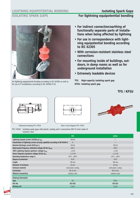
Isolating Spark Gaps<br />
For lightning equipotential bonding<br />
• For indirect connection/earthing of<br />
functionally separate parts of installations<br />
when being affected by lightning<br />
• For use in correspondence with lightning<br />
equipotential bonding according<br />
to IEC 62305<br />
• With corrosion-resistant stainless steel<br />
connections<br />
• For mounting inside of buildings, outdoors,<br />
in damp rooms as well as for<br />
underground installation<br />
• Extremely loadable devices<br />
For lightning equipotential bonding according to IEC 62305 as well as<br />
for use in IT installations according to IEC 60364-5-54.<br />
TFS: High-capacity isolating spark gap<br />
KFSU: Isolating spark gap<br />
TFS / KFSU<br />
923 023 TFS<br />
923 021 KFSU<br />
TFS<br />
Isolating<br />
Spark Gap 923 023<br />
KFSU<br />
Ex-<br />
Isolating Spark Gap 923 021<br />
Dimension drawing TFS / KFSU<br />
Basic circuit diagram TFS / KFSU<br />
TFS / KFSU: Isolating spark gaps with plastic coating and 2 connections (Rd 10 mm) made of<br />
stainless steel<br />
Lightning impulse current (10/350 µs) I imp 100 kA —<br />
Classfication of lightning current carrying capability according to EN 50164-3 H —<br />
Nominal discharge current (8/20 µs) I n 100 kA 100 kA<br />
Rated power-frequency withstand voltage (50 Hz) U W/AC 300 V 300 V<br />
100% Lightning impulse sparkover voltage U rimp 4 kV 4 kV<br />
Power frequency sparkover voltage (50 Hz) U aw 2.5 kV 2.5 kV<br />
Operating temperature range T U -20°C...+80°C -20°C...+80°C<br />
Degree of protection IP 65 IP 65<br />
Length 160 mm 160 mm<br />
Diameter of enclosure 43 mm 43 mm<br />
Enclosure material steel-plastic coating steel-plastic coating<br />
Connection Rd 10 mm Rd 10 mm<br />
Material (connection) stainless steel stainless steel<br />
Ordering information<br />
Type TFS KFSU<br />
Part No. 923 023 923 021<br />
Packing unit 1 pc(s). 1 pc(s).<br />
TFS<br />
KFSU<br />
www.dehn.de<br />
299
EXFS 100 / EXFS 100 KU<br />
For use in hazardous areas<br />
<strong>LIGHTNING</strong> <strong>EQUIPOTENTIAL</strong> <strong>BONDING</strong><br />
<strong>ISOLATING</strong> <strong>SPARK</strong> <strong>GAPS</strong><br />
ATEX-certified isolating spark gap for lightning equipotential bonding<br />
according to IEC 62305 with low sparkover voltage<br />
• For indirect connection/earthing of functionally<br />
separate parts of installations<br />
when being affected by lightning<br />
• Device for lightning equipotential bonding<br />
according to IEC 62305 in hazardous<br />
areas<br />
• For bridging insulating pieces, insulating<br />
flanges etc. in cathodic protected pipe<br />
sections<br />
• For safe application in explosion protection<br />
zone 1 (gases) or 21 (dust)<br />
• Considerably low sparkover voltage<br />
• Considerably high a.c. current withstand<br />
capability<br />
EXFS 100: Isolating spark gap for use in hazardous areas with plastic coating and threaded M10 sockets<br />
EXFS 100 KU: Isolating spark gap for use in hazardous areas with 2 m connecting cables for underground installation<br />
The Ex isolating spark gaps of the EXFS 100 / EXFS 100 KU product family<br />
are used when conductive parts of installations situated in hazardous<br />
areas cannot be connected directly with each other.<br />
The low sparkover voltages of the spark gaps have proved themselves for<br />
protection especially for separate installation parts with only low insulation<br />
resistance against each other.<br />
No special regulations have to be observed for safe application in zone 1<br />
with gas atmospheres or zone 21 with combustible dust.<br />
With a tested maximum lightning impulse current of 100 kA (10/350 μs),<br />
EXFS 100 and EXFS 100 KU meet class H, i.e. the maximum class of lightning<br />
impulse current strength according to EN 50164-3 ”Lightning<br />
Protection Components (LPC) - Part 3: Requirements for isolating spark<br />
gaps“.<br />
The ATEX-certified spark gaps EXFS 100 and EXFS 100 KU provide<br />
approved safety according to harmonised European standards.<br />
For connecting EXFS 100 spark gaps, prewired connecting cables with different<br />
lengths are available as accessories.<br />
Flat and angled connection brackets (IF) make it easier to connect the<br />
spark gaps to pipe flanges.<br />
EXFS 100 KU types are enclosed by a damp-proof plastic coating and can<br />
therefore be ideally used for underground installation for insulating couplings.<br />
Type examination certificate<br />
300 www.dehn.de
923 100 EXFS 100<br />
<strong>LIGHTNING</strong> <strong>EQUIPOTENTIAL</strong> <strong>BONDING</strong><br />
<strong>ISOLATING</strong> <strong>SPARK</strong> <strong>GAPS</strong><br />
EXFS 100 / EXFS 100 KU<br />
EXFS 100<br />
EXFS 100<br />
923 100<br />
NEW<br />
Dimension drawing EXFS 100<br />
Installation of EXFS 100<br />
EXFS 100:<br />
Isolating spark gap for use in hazardous zones with plastic coating and threaded<br />
M10 sockets<br />
EXFS 100<br />
Lightning impulse current (10/350 µs) I imp<br />
100 kA<br />
Class of lightning impulse current strength according to EN 50164-3<br />
H<br />
Nominal discharge current (8/20 µs) I n<br />
100 kA<br />
Rated power-frequency withstand voltage (50 Hz) U W/AC<br />
250 V<br />
100% Lightning impulse sparkover voltage U rimp 1.25 kV<br />
Power-frequency sparkover voltage (50 Hz) U aw<br />
0.5 kV<br />
Rated discharge current (50 Hz) I max 500 A / 0.5 sec. (T U: 45°C)<br />
(Ex) Marking according to EN 60079 (gas atmospheres)<br />
II 2G Ex d IIC T6<br />
(Ex) Marking according to EN 61241 (combustible dust) II 2D Ex tD A21 IP67 T 80°C<br />
Operating temperature range T U<br />
-20°C...+60°C<br />
Degree of protection IP 67<br />
Approvals, Certifications BVS 06 ATEX E 099<br />
Length of enclosure<br />
100 mm<br />
Diameter of enclosure<br />
45,5 mm<br />
Enclosure material<br />
plastic coating<br />
Connection of enclosure<br />
threaded M10 socket, 2x M10x25 mm, 2x spring washer<br />
Ordering information<br />
Type EXFS 100<br />
Part No. 923 100<br />
Packing unit<br />
1 pc(s).<br />
Accessory Part for EXFS 100<br />
Accessory Part for EXFS 100 / EXFS 100 KU<br />
EXFS 100: Connecting cable, Cu 25 mm 2<br />
Connecting cable for EXFS 100;<br />
2 x cable lug Ø10.5 mm, hexagon screw and nut (M10),<br />
StSt (V2A) and spring washer<br />
Cable lug Cross Cable PU Part<br />
Type material section length pc(s) No.<br />
AL EXFS L100 KS Cu/gal Sn 25 mm 2 100 mm 1 923 025<br />
AL EXFS L200 KS Cu/gal Sn 25 mm 2 200 mm 1 923 035<br />
AL EXFS L300 KS Cu/gal Sn 25 mm 2 300 mm 1 923 045<br />
923 025 AL EXFS<br />
L100 KS<br />
923 035 AL EXFS<br />
L200 KS<br />
923 045 AL EXFS<br />
L300 KS<br />
AL EXFS L100 KS<br />
923 025<br />
AL EXFS L200 KS<br />
923 035<br />
AL EXFS L300 KS<br />
923 045<br />
NEW<br />
Pair of angled connection brackets – IF 1 –<br />
Pair of angled connection brackets for EXFS ...;<br />
Diameter corresponds to bolt diameter of the flange screw<br />
joint (allows for max. 60 mm for d1, please confirm the<br />
diameter required when placing your order)<br />
PU Part<br />
Type Material pc(s) No.<br />
IF1 St/tZn 1 923 011<br />
923 011 IF1<br />
IF1<br />
Connection Bracket Type IF -SET- 923 011<br />
Pair of flat connection brackets – IF 3 –<br />
Pair of flat connection brackets for EXFS ...;<br />
Diameter corresponds to bolt diameter of the flange screw<br />
joint (allows for max. 60 mm for d1, please confirm the diameter<br />
required when placing your order)<br />
PU Part<br />
Type Material pc(s) No.<br />
IF3 St/tZn 1 923 016<br />
923 016 IF3<br />
IF3<br />
Connection Bracket Type IF -SET- 923 016<br />
www.dehn.de<br />
301
EXFS 100 / EXFS 100 KU<br />
EXFS 100 KU<br />
<strong>LIGHTNING</strong> <strong>EQUIPOTENTIAL</strong> <strong>BONDING</strong><br />
<strong>ISOLATING</strong> <strong>SPARK</strong> <strong>GAPS</strong><br />
923 101 EXFS 100<br />
KU<br />
NEW<br />
EXFS 100 KU<br />
923 101<br />
isolating spark gap/<br />
Funkenstrecke<br />
insulating piece/<br />
Isolierstück<br />
insulation / Isolierung<br />
Installation of EXFS 100 KU<br />
Dimension drawing EXFS 100 KU<br />
EXFS 100 KU:<br />
Ex isolating spark gap with connecting cable for aboveground and underground<br />
installation<br />
EXFS 100 KU<br />
Lightning impulse current (10/350 µs) I imp<br />
100 kA<br />
Class of lightning impulse current strength according to EN 50164-3<br />
H<br />
Nominal discharge current (8/20 µs) I n<br />
100 kA<br />
Rated power-frequency withstand voltage (50 Hz) U W/AC<br />
250 V<br />
100% Lightning impulse sparkover voltage U rimp 1.25 kV<br />
Power-frequency sparkover voltage (50 Hz) U aw<br />
0.5 kV<br />
Rated discharge current (50 Hz) I max 500 A / 0.5 sec. (T U: 45°C)<br />
(Ex) Marking according to EN 60079 (gas atmospheres)<br />
II 2G Ex d IIC T6<br />
(Ex) Marking according to EN 61241 (combustible dust) II 2D Ex tD A21 IP 67 T 80°C<br />
Operating temperature range T U<br />
-20°C...+60°C<br />
Degree of protection IP 67<br />
Approvals, Certifications BVS 06 ATEX E 099<br />
Length of enclosure<br />
123 mm<br />
Diameter of enclosure<br />
34 mm<br />
Enclosure material<br />
plastic coating; water-proof coating<br />
Connection of enclosure<br />
NYY-J-1x25 mm 2 , approx. 2 m long<br />
Ordering information<br />
Type<br />
EXFS 100 KU<br />
Part No. 923 101<br />
Packing unit<br />
1 pc(s).<br />
302 www.dehn.de
<strong>LIGHTNING</strong> <strong>EQUIPOTENTIAL</strong> <strong>BONDING</strong><br />
<strong>ISOLATING</strong> <strong>SPARK</strong> <strong>GAPS</strong><br />
EXFS L / EXFS KU<br />
For use in hazardous areas<br />
ATEX-certified isolating spark gap for lightning equipotential bonding<br />
according to IEC 62305, approved device with flexible conductor connection<br />
• For indirect connection/earthing of<br />
functionally separate parts of installations<br />
when being affected by lightning<br />
• Device for lightning equipotential bonding<br />
according to IEC 62305 in hazardous<br />
areas (Zone 2)<br />
• Corresponds to ”ATEX Directive“<br />
94/9/EC<br />
• Corrosion-resistant enclosure made of<br />
zinc die casting with plastic cover and<br />
flexible conductor connection<br />
• For bridging insulating pieces, insulating<br />
flanges etc. in pipe sections with<br />
cathodic corrosion protection<br />
• Highly loadable unit<br />
EXFS L ...: Isolating spark gap for use in hazardous areas with flexible connecting cable<br />
EXFS KU: Isolating spark gap for use in hazardous areas with 1.5 m connecting cables for underground installation<br />
The Ex isolating spark gaps of the EXFS L / EXFS KU product family are<br />
used for conductive parts of an installation which cannot be interconnected<br />
directly in hazardous areas. This affects, for example, pipe sections supplied<br />
with a cathodic corrosion protection system.<br />
ATEX-certified EXFS L and EXFS KU spark gaps provide approved and tested<br />
safety in accordance with harmonised European standards.<br />
The arc-resistant tungsten-copper electrodes ensure a long service life of<br />
the Ex spark gaps.<br />
The approved type EXFS L with flexible conductor connection adjusts itself<br />
quickly to any application environment. The prewired spark gaps provide<br />
connecting cables with different lengths with cable lugs, M10 screws and<br />
nuts. The flat or angled connection brackets (IF), which are available as<br />
accessories, allow for easy connection of the spark gap to pipeline<br />
flanges.<br />
Type EXFS KU is enclosed by a damp-proof PVC enclosure and can be ideally<br />
used for underground installation at insulating couplings.<br />
www.dehn.de<br />
303
EXFS L / EXFS KU<br />
EXFS L<br />
<strong>LIGHTNING</strong> <strong>EQUIPOTENTIAL</strong> <strong>BONDING</strong><br />
<strong>ISOLATING</strong> <strong>SPARK</strong> <strong>GAPS</strong><br />
923 060 EXFS<br />
L100<br />
923 061 EXFS<br />
L200<br />
923 062 EXFS<br />
L300<br />
EXFS L100<br />
Ex-<br />
Isolating Spark Gap 923 060<br />
EXFS L200<br />
Ex-<br />
Isolating Spark Gap 923 061<br />
EXFS L300<br />
Ex-<br />
Isolating Spark Gap 923 062<br />
l max = 300 mm<br />
(avoid loops<br />
where possible)<br />
Installation of EXFS<br />
Dimension drawing EXFS<br />
EXFS L ...: Ex isolating spark gap for aboveground installation<br />
EXFS L100 EXFS L200 EXFS L300<br />
Lightning impulse current (10/350 µs) I imp 50 kA 50 kA 50 kA<br />
Classfication of lightning current carrying capability<br />
according to EN 50164-3 N N N<br />
Nominal discharge current (8/20 µs) I n 100 kA 100 kA 100 kA<br />
Rated power-frequency withstand voltage (50 Hz) U W/AC 300 V 300 V 300 V<br />
100% Lightning impulse sparkover voltage U rimp 2.5 kV 2.5 kV 2.5 kV<br />
Power frequency sparkover voltage (50 Hz) U aw 1.2 kV 1.2 kV 1.2 kV<br />
Type of protection according to EN 50014, EN 50021 II 3 G EEx nC II T4 II 3 G EEx nC II T4 II 3 G EEx nC II T4<br />
Operating temperature range T U -20°C...+80°C -20°C...+80°C -20°C...+80°C<br />
Degree of protection IP 54 IP 54 IP 54<br />
Approvals, Certifications ZELM 03 ATEX 3192X ZELM 03 ATEX 3192X ZELM 03 ATEX 3192X<br />
Length of enclosure 90 mm 90 mm 90 mm<br />
Diameter of enclosure 63 mm 63 mm 63 mm<br />
Enclosure material zinc die casting, plastic zinc die casting, plastic zinc die casting, plastic<br />
Connecting cable<br />
H01N2-D 25 mm 2 with cable lug and screw/nut (M10)<br />
Cable length 100 mm 200 mm 300 mm<br />
Suitable for flange size 20-130 mm 120-230 mm 220-320 mm<br />
Ordering information<br />
Type EXFS L100 EXFS L200 EXFS L300<br />
Part No. 923 060 923 061 923 062<br />
Packing unit 1 pc(s). 1 pc(s). 1 pc(s).<br />
IF1<br />
Connection Bracket Type IF -SET- 923 011<br />
Accessory Part for EXFS L / EXFS KU<br />
923 011 IF1<br />
Pair of angled connection brackets – IF 1 –<br />
Pair of angled connection brackets for EXFS ...;<br />
Diameter corresponds to bolt diameter of the flange screw<br />
joint (allows for max. 60 mm for d1, please confirm the<br />
diameter required when placing your order)<br />
PU Part<br />
Type Material pc(s) No.<br />
IF1 St/tZn 1 923 011<br />
IF3<br />
Connection Bracket Type IF -SET- 923 016<br />
Accessory Part for EXFS L / EXFS KU<br />
923 016 IF3<br />
Pair of flat connection brackets – IF 3 –<br />
Pair of flat connection brackets for EXFS ...;<br />
Diameter corresponds to bolt diameter of the flange screw<br />
joint (allows for max. 60 mm for d1, please confirm the diameter<br />
required when placing your order)<br />
PU Part<br />
Type Material pc(s) No.<br />
IF3 St/tZn 1 923 016<br />
304 www.dehn.de
923 019 EXFS KU<br />
<strong>LIGHTNING</strong> <strong>EQUIPOTENTIAL</strong> <strong>BONDING</strong><br />
<strong>ISOLATING</strong> <strong>SPARK</strong> <strong>GAPS</strong><br />
EXFS L / EXFS KU<br />
EXFS KU<br />
EXFS KU<br />
Ex-<br />
Isolating Spark Gap 923 019<br />
Dimension drawing EXFS KU<br />
EXFS KU: Ex isolating spark gap with connecting cables for aboveground<br />
and underground installation<br />
EXFS KU<br />
Lightning impulse current (10/350 µs) I imp<br />
50 kA<br />
Classfication of lightning current carrying capability according to EN 50164-3 N<br />
Nominal discharge current (8/20 µs) I n<br />
100 kA<br />
Rated power-frequency withstand voltage (50 Hz) U W/AC<br />
300 V<br />
100% Lightning impulse sparkover voltage U rimp 2.5 kV<br />
Power frequency sparkover voltage (50 Hz) U aw<br />
1.2 kV<br />
Type of protection according to EN 50014, EN 50021<br />
II 3 G EEx nC II T4<br />
Operating temperature range T U<br />
-20°C...+80°C<br />
Degree of protection IP 67<br />
Approvals, Certifications<br />
ZELM 03 ATEX 3192X<br />
Length of enclosure<br />
90 mm<br />
Diameter of enclosure<br />
63 mm<br />
Enclosure material<br />
zinc die casting, plastic<br />
Connecting cable NYY-J-1x25 mm 2<br />
Cable length<br />
2 x approx. 1500 mm<br />
Ordering information<br />
Type<br />
EXFS KU<br />
Part No. 923 019<br />
Packing unit<br />
1 pc(s).<br />
www.dehn.de<br />
305
Pipe Clamp for use in hazardous Areas <strong>LIGHTNING</strong> <strong>EQUIPOTENTIAL</strong> <strong>BONDING</strong><br />
For fixing at pipes installed in hazardous areas<br />
• For use in potentially explosive areas,<br />
i.e. Ex zones 1 and 2 (gases, vapours,<br />
fog) and Ex zones 21 and 22 (dust)<br />
• Tested according to explosion group IIB<br />
• Considerable saving of time for installation<br />
– no more deactivation of the<br />
installation/zone required for welding<br />
or drilling work<br />
Pipe clamp for use in hazardous areas from ¬“ to 3“ and<br />
3“ to D = 300 mm.<br />
Separate clamping element for continuous tightening<br />
strap (Part No. 540 901) from ¬“ to D = 300 mm.<br />
Pipe clamp for attaching to pipes in hazardous areas for lightning<br />
equipotential bonding according to EN 62305-3 (DIN VDE 0185-305-3)<br />
So far, connections for equipotential bonding and lightning equipotential<br />
bonding in hazardous areas have often been welded or provided as<br />
threaded sockets. Using clamps was only permitted if their ignition-proofness<br />
had been verified before. DEHN + SÖHNE has now provided evidence<br />
of no ignition of a pipe clamp affected by lightning currents. By<br />
testing according to DIN EN 50164-1 (VDE 0185-201) (Requirements for<br />
connection components) in a potentially explosive atmosphere, no ignition<br />
of the test sample with a lightning current carrying capability up to<br />
50 kA (10/350 μs) was verified. The design of this new pipe clamp takes<br />
both a safe electrical contact by means of two contact clips into consideration<br />
as well as the mechnanical fixation by an electrically insulated<br />
clamping element per clip. The pipe clamp can be attached by means of<br />
– round conductors, Cu, St/tZn, Al, StSt with Ø8 mm or stranded copper<br />
conductors, cross section 16-35 mm 2, with E-Cu crimping cable lug<br />
(DIN 46235)<br />
– flat copper conductors with minimum dimensions of 20 x 2.5 mm and<br />
a Ø10.5 mm hole.<br />
Attached to a StSt pipe<br />
Accessory Part for Pipe Clamp for use in hazardous Areas<br />
540 901<br />
540 901<br />
Tensioning strap<br />
Continuous tensioning strap (100 m long)<br />
Strap dimension PU Part<br />
Material (l1 x w x d) pc(s) No.<br />
StSt (V2A) ... x 25 x 0.3 mm 1 540 901<br />
306 www.dehn.de
540 801<br />
540 803<br />
<strong>LIGHTNING</strong> <strong>EQUIPOTENTIAL</strong> <strong>BONDING</strong> Pipe Clamp for use in hazardous Areas<br />
Pipe clamp for use in hazardous areas for ¬“ to D = 300 mm<br />
540 801<br />
NEW<br />
540 803<br />
Pipe clamp for use in hazardous areas in<br />
zones 1 and 21;<br />
Clamping ranges from ¬“ to 3“ and 3“ to<br />
D=300 mm<br />
Lightning impulse current (10/350 µs) for Cu I imp 50 kA 50 kA<br />
Lightning impulse current (10/350 µs) for St/tZn I imp 50 kA 50 kA<br />
Lightning impulse current (10/350 µs) for StSt I imp 25 kA 50 kA<br />
Lightning current carrying capability according to DIN EN 50164-1<br />
(does not apply to StSt, 25 kA) Class N Class N<br />
Pipe clamping range Ø 26.9-88.9 mm 88.9-300 mm<br />
Clamping range ¬’’ – 3’’ 3’’ – Ø300 mm<br />
Dimension of tightening strap (l1 x w x d) 410x25x0.3 mm 1100x25x0.3 mm<br />
Clamping element material polyamide polyamide<br />
Head/Strap material StSt (V2A) StSt (V2A)<br />
Contact angle material Cu/gal Sn Cu/gal Sn<br />
Ordering information<br />
Part No. 540 801 540 803<br />
Packing unit 1 pc(s). 1 pc(s).<br />
540 810<br />
Separate clamping element for continuous tightening strap<br />
540 810<br />
NEW<br />
Separate clamping element for combination<br />
with continuous tightening strap (Part No.<br />
540 901) for use in hazardous zones 1 and<br />
21; clamping range from ¬“ to D=300 mm<br />
Lightning impulse current (10/350 µs) for Cu I imp<br />
Lightning impulse current (10/350 µs) for St/tZn I imp<br />
Lightning impulse current (10/350 µs) for StSt I imp<br />
Lightning current carrying capability according to DIN EN 50164-1<br />
(does not apply to StSt, 25 kA)<br />
Pipe clamping range Ø<br />
Clamping range<br />
Clamping element material<br />
Head/Strap material<br />
Contact angle material<br />
50 kA<br />
50 kA<br />
25 kA<br />
Class N<br />
max. 300 mm<br />
¬’’ – Ø300 mm<br />
polyamide<br />
StSt (V2A)<br />
Cu/gal Sn<br />
Ordering information<br />
Part No. 540 810<br />
Packing unit<br />
1 pc(s).<br />
www.dehn.de<br />
307
SDS<br />
Voltage limiting device<br />
<strong>LIGHTNING</strong> <strong>EQUIPOTENTIAL</strong> <strong>BONDING</strong><br />
<strong>ISOLATING</strong> <strong>SPARK</strong> <strong>GAPS</strong><br />
• Electrical isolation of insulated track<br />
sections and earthed parts of installations<br />
• Safe equipotential bonding by heavycurrent-resistant<br />
welding of the electrodes<br />
in case of a short circuit or earth<br />
fault at the overhead contact line<br />
• Discharging of surges without generating<br />
short circuits due to lightning-resistant<br />
SDS ... voltage limiting device<br />
• Short-circuit withstand capability<br />
25 kA rms / 100 ms; 36 kA rms / 75 ms<br />
SDS ...: SDS Spark gap unit, cylindrical design for supporting Siemens rail adapter No. 431.34<br />
SDS ... NH00: SDS Spark gap unit for support in NH fuse holders, size 00<br />
DIN EN 50122-1 defines the use of voltage limiting devices for d.c. and<br />
a.c. railways for socalled ”open earthing of railways“ for components of<br />
overhead contact lines and current collectors.<br />
In order to prevent any upcoming of hazardous surges between the insulated<br />
rails or rail sections of electrical railways and earthed parts of the<br />
installation, voltage limiting devices (SDS ...) are used.<br />
Their function is to connect parts of the installation in overhead contact<br />
lines and current collectors permanently with the return circuit, as soon as<br />
the threshold voltage is exceeded.<br />
In case of atmospherical overvoltages, the lightning-resistant SDS ... voltage<br />
limiting device is capable of returning to the initial condition after discharging<br />
impulse currents. Only if the provided lightning current loads are<br />
exceeded, a permanent short circuit is initiated by heavy-current-resistant<br />
welding of the electrodes. Then, as a consequence, the fuse link has to be<br />
replaced.<br />
mostly unnecessary<br />
SDS spark gap unit for use with rail adapter of Siemens,<br />
type No. 431.34<br />
The SDS voltage limiting device consists of a spark gap unit and the<br />
respective terminal set for direct connection with the rail or overhead contact<br />
line tower.<br />
The spark gap unit type SDS 1, Part No. 923 110, developed by DEHN +<br />
SÖHNE, has also been approved by the German Federal Railway Authority<br />
(EBA).<br />
Type SDS ... NH 00 is designed for installation into NH00 fuse holders or<br />
insulators. In connection with DEHNisola leakage current detecting<br />
device, the user can localise a short-circuited spark-gap unit quickly and<br />
easily.<br />
SDS 2 NH00 installed into a mains connection box with DEHNisola<br />
combined operating state monitoring device<br />
308 www.dehn.de
923 110 SDS 1<br />
<strong>LIGHTNING</strong> <strong>EQUIPOTENTIAL</strong> <strong>BONDING</strong><br />
<strong>ISOLATING</strong> <strong>SPARK</strong> <strong>GAPS</strong><br />
SDS<br />
SDS ...<br />
SDS 1<br />
Sicherungseinsatz SDS 1 923 110<br />
NEW<br />
Dimension drawing SDS ...<br />
Basic circuit diagram SDS ...<br />
SDS 1 SDS 2 SDS 3 SDS 4 SDS 5<br />
Power frequency sparkover voltage U aw 940 V –– –– –– ––<br />
d.c. Sparkover voltage U ag 600 V +/- 20 % 350 V +/- 20 % 550 V 230 V +/- 20 % 120 V +/- 20 %<br />
Impulse sparkover voltage 1400 V (1 kV/μs) 900 V (1 kV/μs) 1000 V (1 kV/μs) 650 V (1 kV/μs) 600 V (1 kV/μs)<br />
Self-extinguishing capability 300 A / 65 V –– –– –– ––<br />
Lightning current discharge capacity<br />
(10/350 µs) 0.1; 0.5; 1x I imp 5 kA 2 kA 5 kA 3 kA 2 kA<br />
Lightning current withstand capability (10/350 µs) 25 kA 25 kA 25 kA 25 kA 25 kA<br />
Impulse current discharge capacity (8/20 µs) 0.1; 0.5; 1x –– –– –– 20 kA 20 kA<br />
Safe short circuit due to welding of the<br />
electrodes for a.c. currents of 100 ms 1.5 kA / 1000 V / 100 ms –– –– –– ––<br />
Safe short circuit due to welding of the<br />
electrodes for a.c. currents of 30 ms 2.5 kA / 1000 V / 30 ms –– –– –– ––<br />
Safe short circuit due to welding of the<br />
electrodes for d.c. currents 750 A / 250 ms 600 A / 250 ms 600 A / 250 ms 600 A / 250 ms 600 A / 250 ms<br />
Short circuit withstand capability 25 kA rms / 100 ms; 25 kA rms / 100 ms; 25 kA rms / 100 ms; 25 kA rms / 100 ms; 25 kA rms / 100 ms;<br />
36 kA rms / 75 ms 36 kA rms / 75 ms 36 kA rms / 75 ms 36 kA rms / 75 ms 36 kA rms / 75 ms<br />
Long-term current 1 kA rms for t 120 s 1 kA rms for t 120 s 1 kA rms for t 120 s 1 kA rms for t 120 s 1 kA rms for t 120 s<br />
Leakage current I lc < 1 μA for 100 V d.c. < 1 μA for 100 V d.c. < 1 μA for 100 V d.c. < 1 μA for 100 V d.c. < 1 μA for 100 V d.c.<br />
Operating temperature range T U -40°C...+80°C -40°C...+80°C -40°C...+80°C -40°C...+80°C -40°C...+80°C<br />
For mounting on allows for installation into voltage breakdown protector/rail adapter of SIEMENS No. 431.34<br />
Tightening torque of the fuse link in the<br />
busbar adapter 15 Nm 15 Nm 15 Nm 15 Nm 15 Nm<br />
Approvals, Certifications EBA –– –– –– ––<br />
DB Drawing No. 4 Ebs 15.13.20 Blatt 2 –– –– –– ––<br />
Ordering information<br />
Type SDS 1 SDS 2 SDS 3 SDS 4 SDS 5<br />
Part No. 923 110 923 117 923 116 923 118 923 119<br />
Packing unit 10 pc(s). 10 pc(s). 10 pc(s). 10 pc(s). 10 pc(s).<br />
www.dehn.de<br />
309
SDS<br />
SDS ... in NH 00 enclosure<br />
<strong>LIGHTNING</strong> <strong>EQUIPOTENTIAL</strong> <strong>BONDING</strong><br />
<strong>ISOLATING</strong> <strong>SPARK</strong> <strong>GAPS</strong><br />
923 123 SDS 2<br />
NH00<br />
NEW<br />
SDS 2 NH00<br />
Sicherungseinsatz SDS 2 NH00 923 123<br />
Basic circuit diagram SDS ... NH00<br />
Dimension drawing SDS ... NH00<br />
SDS 2 NH00 SDS 4 NH00 SDS 5 NH00<br />
d.c. Sparkover voltage U ag 350 V +/- 20 % 230 V +/- 20 % 120 V +/- 20 %<br />
Impulse sparkover voltage 900 V (1 kV/μs) 650 V (1 kV/μs) 600 V (1 kV/μs)<br />
Lightning current discharge capacity (10/350 µs) 0.1; 0.5; 1x I imp 2 kA 3 kA 2 kA<br />
Lightning current withstand capability (10/350 µs) 25 kA 25 kA 25 kA<br />
Safe short circuit due to welding of the<br />
electrodes for d.c. currents 600 A / 250 ms 600 A / 250 ms 600 A / 250 ms<br />
Short circuit withstand capability 10 kA / 50 ms 10 kA / 50 ms 10 kA / 50 ms<br />
Long-term current 1 kA rms for t 120 s 1 kA rms for t 120 s 1 kA rms for t 120 s<br />
Leakage current I lc < 1 μA for 100 V d.c. < 1 μA for 100 V d.c. < 1 μA for 100 V d.c.<br />
Operating temperature range T U -40°C...+80°C -40°C...+80°C -40°C...+80°C<br />
For mounting on NH fuse holder, size 00 NH fuse holder, size 00 NH fuse holder, size 00<br />
Enclosure material red thermoplastic, UL 94 V-0 red thermoplastic, UL 94 V-0 red thermoplastic, UL 94 V-0<br />
Min. degree of protection for enclosures IP 54 IP 54 IP 54<br />
Ordering information<br />
Type SDS 2 NH00 SDS 4 NH00 SDS 5 NH00<br />
Part No. 923 123 923 126 923 127<br />
Packing unit 1 pc(s). 1 pc(s). 1 pc(s).<br />
310 www.dehn.de
<strong>LIGHTNING</strong> <strong>EQUIPOTENTIAL</strong> <strong>BONDING</strong><br />
Equipotential Bonding<br />
Equipotential Bonding Bars<br />
Accessories / Construction Kit<br />
K 12 Equipotential bonding bars<br />
with snap-on terminals<br />
For main equipotential bonding according to DIN VDE 0100<br />
Part 410/540 and lightning equipotential bonding according<br />
to EN 62305-3 (DIN VDE 0185-305-3)<br />
Type K12 with 12 contact studs:<br />
10 terminals for Rd 2.5 – 95 mm 2 conductors or<br />
10 terminals for Rd 10 mm conductors and 1 terminal<br />
for Fl -30x4 mm conductors<br />
Contact Cross PU Part<br />
Type bar section pc(s) No.<br />
PAS 11AK Cu/gal Sn 30 mm 2 1 563 200<br />
K 12 Equipotential bonding bars<br />
with snap-on terminals<br />
UV-stabilised device<br />
Contact Cross PU Part<br />
Type bar section pc(s) No.<br />
PAS 11AK UV Cu/gal Sn 30 mm 2 1 563 201<br />
563 200 PAS 11AK<br />
PAS 11AK<br />
Potentialausgleichsschiene 563 200<br />
563 201 PAS 11AK<br />
UV<br />
PAS 11AK UV<br />
563 201<br />
Terminal blocks<br />
Up to 16 mm 2 PU Part<br />
Type Material Connection Modules pc(s) No.<br />
RK 16 PAS StSt (V2A)- 2.5-16 mm 2 1 200 563 011<br />
St/gal Zn<br />
Terminal blocks<br />
Up to 95 mm 2 or Rd 8-10 mm<br />
PU Part<br />
Type Material Connection Modules pc(s) No.<br />
RK 95 PAS St/gal Zn 16-95 mm 2 2 100 563 013<br />
Terminal blocks<br />
Flat conductor 30 mm<br />
PU Part<br />
Type Material Connection Modules pc(s) No.<br />
RK FL30 PAS St/gal Zn -30x4 mm 2 4 25 563 012<br />
563 011 RK 16<br />
PAS<br />
RK 16 PAS<br />
Reihenklemme -16mm für PAS 563 011<br />
563 013 RK 95<br />
PAS<br />
RK 95 PAS<br />
Reihenklemme 16-95 mm für PAS 563 013<br />
563 012 RK FL30<br />
PAS<br />
RK FL30 PAS<br />
Reihenklemme Fl -30 mm für PAS 563 012<br />
Accessories –<br />
Snap-on terminal for Fl 40 conductors<br />
Connections Reservation of PU Part<br />
Type Fl mm Material contact studs pc(s) No.<br />
AK FL40 PAS 1x -40x5 St/gal Zn 3 50 563 222<br />
563 222 AK FL40<br />
PAS<br />
AK FL40 PAS<br />
Aufsteckklemme für PAS, TYP K 12 563 222<br />
Terminal blocks<br />
Flat conductor 40 mm<br />
PU Part<br />
Type Material Connection Modules pc(s) No.<br />
RK FL40 PAS St/gal Zn -40x5 mm 2 5 25 563 019<br />
563 019 RK FL40<br />
PAS<br />
RK FL40 PAS<br />
Reihenklemme Fl -40 mm für PAS 563 019<br />
MS Equipotential bonding bars<br />
For main equipotential bonding according to DIN VDE 0100<br />
Part 410/540<br />
Connections for<br />
7 Rd conductors 2.5 – 16 mm 2<br />
1 Rd conductor 7 – 10 mm<br />
1 Fl conductor -30x3.5 mm or Rd conductor 8 – 10 mm<br />
Contact Cross PU Part<br />
Type bar section pc(s) No.<br />
PAS 9AK MS 50 mm 2 1 563 050<br />
R15 Equipotential bonding bars<br />
with terminal block system<br />
For main equipotential bonding according to DIN VDE 0100<br />
Part 410/540 and lightning equipotential bonding according<br />
to EN 62305-3 (DIN VDE 0185-305-3)<br />
Type A:<br />
7 terminal blocks for Rd conductors 2.5 – 16 mm 2<br />
2 terminal blocks for Rd conductors 16 – 95 mm 2<br />
or Rd conductors 8 – 10 mm<br />
1 terminal block Fl -30x4 mm<br />
Clamping Cross PU Part<br />
Type bar section pc(s) No.<br />
PAS 10RK Ms/gal Sn 100 mm 2 1 563 010<br />
563 050 PAS 9AK<br />
PAS 9AK<br />
563 050<br />
563 010 PAS 10RK<br />
PAS 10RK<br />
Potentialausgleichsschiene 563 010<br />
Clamping bar<br />
PU Part<br />
Type Material Length Modules pc(s) No.<br />
KS 198 PAS MS/gal Sn 198 mm 15 10 563 016<br />
KS 398 PAS MS/gal Sn 398 mm 30 10 563 017<br />
KS 798 PAS MS/gal Sn 798 mm 60 10 563 018<br />
Bar frame<br />
Fixing PU Part<br />
Type Material holes pc(s) No.<br />
SB PAS RK plastic 6x4 mm 50 563 014<br />
Covers<br />
Snap-on devices<br />
PU Part<br />
Type Material Modules pc(s) No.<br />
AH PAS RK plastic 15 10 563 015<br />
563 016 KS 198<br />
PAS<br />
563 017 KS 398<br />
PAS<br />
563 018 KS 798<br />
PAS<br />
KS 198 PAS<br />
Klemmschiene für PAS, L 198 mm 563 016<br />
KS 398 PAS<br />
Klemmschiene für PAS, L 398 mm 563 017<br />
KS 798 PAS<br />
Klemmschiene für PAS, L 798 mm 563 018<br />
563 014 SB PAS<br />
RK<br />
SB PAS RK<br />
563 014<br />
563 015 AH PAS<br />
RK<br />
AH PAS RK<br />
Abdeckhaube K grau 563 015<br />
Type B:<br />
5 terminal blocks for Rd conductors 2.5 – 16 mm 2<br />
3 terminal blocks for Rd conductors 16 – 95 mm 2<br />
or Rd conductors 8 – 10 mm<br />
1 terminal block Fl -30x4 mm<br />
Clamping Cross PU Part<br />
Type bar section pc(s) No.<br />
PAS 9RK Ms/gal Sn 100 mm 2 1 563 020<br />
563 020 PAS 9RK<br />
PAS 9RK<br />
Potentialausgleichsschiene 563 020<br />
Type C:<br />
13 terminal blocks for Rd conductors 2.5 – 16 mm 2<br />
1 terminal block for Rd conductors 16 – 95 mm 2<br />
or Rd conductors 8 – 10 mm<br />
Clamping Cross PU Part<br />
Type bar section pc(s) No.<br />
PAS 14RK Ms/gal Sn 100 mm 2 1 563 030<br />
563 030 PAS 14RK<br />
PAS 14RK<br />
Potentialausgleichsschiene 563 030<br />
Note: Our complete product range for earthing and equipotential bonding can be taken from our current Lightning Protection catalogue, which,<br />
of course, can also be requested from Export Department.<br />
www.dehn.de<br />
311
Equipotential Bonding<br />
<strong>LIGHTNING</strong> <strong>EQUIPOTENTIAL</strong> <strong>BONDING</strong><br />
Equipotential Bonding Bars<br />
with terminal block system<br />
Equipotential Bonding Bars<br />
Industry<br />
563 105 PAS 6RK<br />
OH<br />
PAS 6RK OH<br />
Potentialausgleichsschiene 563 105<br />
563 103 PAS 7RK<br />
UP<br />
PAS 7RK UP<br />
Potentialausgleichsschiene 563 103<br />
Equipotential bonding bars<br />
with miniature/terminal block system<br />
For main equipotential bonding according to DIN VDE 0100<br />
Part 410/540 in small-sized installations<br />
Miniature unit: For surface mounting without cover<br />
Clamping Cross PU Part<br />
Type bar Connections section pc(s) No.<br />
PAS 6RK OH Ms/gal Sn 6 x 2.5-16 mm 2 100 mm 2 10 563 105<br />
For flush mounting: In box with plastic cover,<br />
white (sealable)<br />
Clamping Cross PU Part<br />
Type bar Connections section pc(s) No.<br />
PAS 7RK UP Ms/gal Sn 7 x 2.5-16 mm 2 100 mm 2 5 563 103<br />
472 207 PAS I 6AP<br />
M10 CU<br />
472 209 PAS I 6AP<br />
M10 V2A<br />
PAS I 6AP M10 CU<br />
Potentialausgleichsschiene 472 207<br />
PAS I 6AP M10 V2A<br />
Potentialausgleichsschiene 472 209<br />
472 227 PAS I 8AP<br />
M10 CU<br />
472 229 PAS I 8AP<br />
M10 V2A<br />
PAS I 8AP M10 CU<br />
Potentialausgleichsschiene 472 227<br />
PAS I 8AP M10 V2A<br />
Potentialausgleichsschiene 472 229<br />
Equipotential bonding bars for industrial<br />
installations<br />
For main equipotential bonding according to DIN VDE 0100<br />
Part 410/540 and lightning equipotential bonding according<br />
to EN 62305-3 (DIN VDE 0185-305-3)<br />
Also for use in hazardous zones (screws protected against<br />
self-loosening)<br />
6 connections with insulators<br />
Dimension Cross PU Part<br />
Type Material (l x w x d) section pc(s) No.<br />
PAS I 6AP M10 CU Cu 295x40x5 mm 200 mm 2 1 472 207<br />
PAS I 6AP M10 V2A StSt (V2A) 295x40x6 mm 240 mm 2 1 472 209<br />
8 connections with insulators<br />
Dimension Cross PU Part<br />
Type Material (l x w x d) section pc(s) No.<br />
PAS I 8AP M10 CU Cu 365x40x5 mm 200 mm 2 1 472 227<br />
PAS I 8AP M10 V2A StSt (V2A) 365x40x6 mm 240 mm 2 1 472 229<br />
472 217 PAS I<br />
10AP M10 CU<br />
472 219 PAS I<br />
10AP M10 V2A<br />
PAS I 10AP M10 CU<br />
Potentialausgleichsschiene 472 217<br />
PAS I 10AP M10 V2A<br />
Potentialausgleichsschiene 472 219<br />
10 connections with insulators<br />
Dimension Cross PU Part<br />
Type Material (l x w x d) section pc(s) No.<br />
PAS I 10AP M10 CU Cu 435x40x5 mm 200 mm 2 1 472 217<br />
PAS I 10AP M10 V2A StSt (V2A) 435x40x6 mm 240 mm 2 1 472 219<br />
472 237 PAS I<br />
12AP M10 CU<br />
472 239 PAS I<br />
12AP M10 V2A<br />
PAS I 12AP M10 CU<br />
Potentialausgleichsschiene 472 237<br />
PAS I 12AP M10 V2A<br />
Potentialausgleichsschiene 472 239<br />
12 connections with insulators<br />
Dimension Cross PU Part<br />
Type Material (l x w x d) section pc(s) No.<br />
PAS I 12AP M10 CU Cu 505x40x5 mm 200 mm 2 1 472 237<br />
PAS I 12AP M10 V2A StSt (V2A) 505x40x6 mm 240 mm 2 1 472 239<br />
472 257 PAS BW<br />
8AP M10 CU<br />
PAS BW 8AP M10 CU<br />
Potentialausgleichsschiene 472 257<br />
8 connections with terminal holes Ø13 mm,<br />
without insulators<br />
Dimension Cross PU Part<br />
Type Material (l x w x d) section pc(s) No.<br />
PAS BW 8AP M10 CU Cu 500x40x5 mm 200 mm 2 1 472 257<br />
472 279 AD PAS<br />
6AP V2A<br />
472 269 AD PAS<br />
8AP V2A<br />
472 289 AD PAS<br />
10AP V2A<br />
472 299 AD PAS<br />
12AP V2A<br />
AD PAS 6AP V2A<br />
Abdeckung NIRO für PAS, 6-polig 472 279<br />
AD PAS 8AP V2A<br />
Abdeckung NIRO für PAS, 8-polig 472 269<br />
AD PAS 10AP V2A<br />
Abdeckung NIRO für PAS, 10-polig 472 289<br />
AD PAS 12AP V2A<br />
Abdeckung NIRO für PAS, 12-polig 472 299<br />
Accessories – Covers for EBB (Industry)<br />
Covers for EBB with insulators<br />
Screw/Nut EB Dimension PU Part<br />
Type material type (l x w x d) pc(s) No.<br />
AD PAS 6AP V2A StSt (V2A) 6 connections 301x60x0.8 mm 1 472 279<br />
AD PAS 8AP V2A StSt (V2A) 8 connections 371x60x0.8 mm 1 472 269<br />
AD PAS 10AP V2A StSt (V2A) 10 connections 441x60x0.8 mm 1 472 289<br />
AD PAS 12AP V2A StSt (V2A) 12 connections 511x60x0.8 mm 1 472 299<br />
472 201 BS M10<br />
PAS<br />
Accessory – Fixing Set for EBB (Industry)<br />
BS M10 PAS<br />
Befestigungsset für PAS 472 201<br />
Screw Screw Plastic PU Part<br />
Type material type dowel pc(s) No.<br />
BS M10 PAS St/tZn 45 mm c M10x20 mm Ø 12x60 mm 1 472 201<br />
472 210 IS PAS<br />
M10<br />
Accessory – Insulator for EBB (Industry)<br />
IS PAS M10<br />
Isolator<br />
für PAS Industrie 472 210<br />
Terminal Dimension PU Part<br />
Type thread (d x h) pc(s) No.<br />
IS PAS M10 M10 32x40 mm 1 472 210<br />
Note: Our complete product range for earthing and equipotential bonding can be taken from our current Lightning Protection catalogue, which,<br />
of course, can also be requested from Export Department.<br />
312 www.dehn.de
<strong>LIGHTNING</strong> <strong>EQUIPOTENTIAL</strong> <strong>BONDING</strong><br />
Equipotential Bonding<br />
Earthing Busbars<br />
Components<br />
for foundation earthing electrodes<br />
Earthing busbars<br />
For screwing or welding at steel structures<br />
2x2 connections<br />
Dimension Cross PU Part<br />
Type Material (l x w x d) section pc(s) No.<br />
PAS 2AP 10 ST St/tZn 196x60x4 mm 240 mm 2 1 472 023<br />
PAS 2AP 10 V2A StSt (V2A) 196x60x5 mm 300 mm 2 1 472 109<br />
472 023 ES 2X2AP<br />
10 ST<br />
472 109 ES 2X2AP<br />
10 V2A<br />
ES 2X2AP 10 ST<br />
472 023<br />
ES 2X2AP 10 V2A<br />
472 109<br />
Distance holder<br />
For installing earth conductors into the foundation level,<br />
includes safety device against loosening of the conductor<br />
Reinforced angled device<br />
Support Support PU Part<br />
Type Material Fl Rd pc(s) No.<br />
AH FE RF V G St/tZn 40 mm 8-10 mm 25 290 001<br />
290 001 AH FE RF<br />
V G<br />
AH FE RF V G<br />
290 001<br />
2x3 connections<br />
Dimension Cross PU Part<br />
Type Material (l x w x d) section pc(s) No.<br />
PAS 3AP 10 ST St/tZn 242x60x4 mm 240 mm 2 1 472 022<br />
PAS 3AP 10 V2A StSt (V2A) 242x60x5 mm 300 mm 2 1 472 119<br />
472 022 ES 2X3AP<br />
10 ST<br />
472 119 ES 2X3AP<br />
10 V2A<br />
ES 2X3AP 10 Stk.<br />
472 022<br />
ES 2X3AP 10 V2A<br />
472 119<br />
Straight unit<br />
Support Support PU Part<br />
Type Material Fl Rd pc(s) No.<br />
AH FE RF St/tZn 40 mm 8-10 mm 50 290 002<br />
290 002 AH FE RF<br />
AH FE RF<br />
290 002<br />
2x4 connections<br />
Dimension Cross PU Part<br />
Type Material (l x w x d) section pc(s) No.<br />
PAS 4AP 10 ST St/tZn 293x60x4 mm 240 mm 2 1 472 024<br />
PAS 4AP 10 V2A StSt (V2A) 293x60x5 mm 300 mm 2 1 472 129<br />
2x6 connections<br />
Dimension Cross PU Part<br />
Type Material (l x w x d) section pc(s) No.<br />
PAS 6AP 10 ST St/tZn 393x60x4 mm 240 mm 2 1 472 021<br />
PAS 6AP 10 V2A StSt (V2A) 393x60x5 mm 300 mm 2 1 472 139<br />
472 024 ES 2X4AP<br />
ST<br />
472 129 ES 2X4AP<br />
10 V2A<br />
ES 2X4AP Stk.<br />
472 024<br />
ES 2X4AP 10 V2A<br />
472 129<br />
472 021 ES 2X6AP<br />
10 ST<br />
472 139 ES 2X6AP<br />
10 V2A<br />
ES 2X6AP 10 Stk.<br />
472 021<br />
ES 2X6AP 10 V2A<br />
472 139<br />
Wedge connector<br />
For T-, cross and parallel connections for use in concrete<br />
foundations<br />
With lock-in position in the wedge<br />
Clamping range PU Part<br />
Type Material Rd / Fl Fl / Fl pc(s) No.<br />
KV FE UNI St/tZn * 10 / 30x3.5-40x4 / 25 308 001<br />
30x3.5-40x4 mm 30x3.5-40x4 mm<br />
* tested with 50 Hz currents<br />
308 001 KV FE UNI<br />
KV FE UNI<br />
Keilverbinder mit Rasterstellung 308 001<br />
Expansion strap for foundation earthing<br />
electrodes<br />
For leading the foundation earthing electrode in expansive<br />
foundations (several sections) through the expansion or isolating<br />
joints, without requiring the leading of the earthing electrode<br />
out of the base plate.<br />
308 150<br />
308 150<br />
Strap Dimension Block PU Part<br />
material (l x w x d) material pc(s) No.<br />
StSt (V2A) approx. 700x30x(4x1) mm styrene 1 308 150<br />
Expansion straps<br />
For compensating expansion joints outside of the concrete<br />
when installing foundation earthing electrodes, with flat<br />
washers and spring washer<br />
Dimension PU Part<br />
Type Material (l x w x t) pc(s) No.<br />
DB FE 235 AL Al 235x45x5 mm 25 308 050<br />
308 050 DB FE 235<br />
AL<br />
DB FE 235 AL<br />
Dehnungsband Al 308 050<br />
Note: Our complete product range for earthing and equipotential bonding can be taken from our current Lightning Protection catalogue, which,<br />
of course, can also be requested from Export Department.<br />
www.dehn.de<br />
313
Equipotential Bonding<br />
<strong>LIGHTNING</strong> <strong>EQUIPOTENTIAL</strong> <strong>BONDING</strong><br />
Connecting Clamps<br />
Components<br />
for ring equipotential bonding<br />
308 025 VK A UNI<br />
ST<br />
VK A UNI Stk.<br />
Verbindungsklemme St/tZn 308 025<br />
Connecting clamps<br />
For building reinforcements, for connecting reinforced concrete<br />
mats or reinforcements with round and flat conductors<br />
Arrangement: (II) = parallel (+) = cross<br />
For T-, cross and parallel connections<br />
Clamping range PU Part<br />
Type Material Rd / Rd Rd / Fl Fl / Fl pc(s) No.<br />
VK A UNI ST St/tZn * (+) 6-10 / (+) 6-10 / (II) 30 / 50 308 025<br />
6-10 mm 30 mm 30 mm<br />
277<br />
FBH<br />
230<br />
6 ST<br />
277 237<br />
FBH CU<br />
277<br />
FBH<br />
239<br />
6 V2A<br />
Flachbandhalter mit Schlitz 12 mm, St/tZn 277 230<br />
Flachbandhalter mit Schlitz 12 mm, Cu 277 237<br />
Flachbandhalter mit Schlitz 12 mm, NIRO 277 239<br />
Support for tape conductors<br />
with pressure plate<br />
For wall mounting with M8 screw<br />
For flat strip up to 6 mm<br />
CH Pressure plate/ PU Part<br />
Type material Screw material pc(s) No.<br />
FBH 6 ST St/tZn StSt (V2A) 25 277 230<br />
FBH 6 CU Cu StSt (V2A) 25 277 237<br />
FBH 6 V2A StSt (V2A) StSt (V2A) 25 277 239<br />
308 026 VK A UNI<br />
V2 ST<br />
VK A UNI V2 Stk.<br />
Verbindungsklemme St/tZn 308 026<br />
For T-, cross and parallel connections<br />
Clamping range PU Part<br />
Type Material Rd / Fl Fl / Fl pc(s) No.<br />
VK A UNI V2 ST St/tZn * (+) 6-10 / (+/II) 30 / 25 308 026<br />
30 mm 30 mm<br />
277<br />
FBH<br />
240<br />
11 ST<br />
Flachbandhalter mit Schlitz 11 mm, St/tZn 277 240<br />
For flat strip up to 11 mm<br />
CH Pressure plate/ PU Part<br />
Type material Screw material pc(s) No.<br />
FBH 11 CU Cu StSt (V2A) 25 277 247<br />
* tested with 50 Hz currents<br />
308 030 VK A R22<br />
F40 STBL<br />
VK A R22 F40 STBL<br />
Verbindungsklemme St/blank 308 030<br />
308 041<br />
MMVK R16<br />
R25 ST<br />
308 040<br />
MMVK R25 STBL R16<br />
Maxi-MV-<br />
Klemme St/tZn 308 041<br />
Maxi-MV-<br />
Klemme St/blank 308 040<br />
For T- and cross connections<br />
Clamping range PU Part<br />
Type Material Rd / Fl pc(s) No.<br />
VK A R22 F40 STBL St/bare (+) 6-22 / 40 mm 25 308 030<br />
Maxi MV clamps for T-, cross and parallel connections<br />
Clamping range PU Part<br />
Type Material Rd / Rd pc(s) No.<br />
MMVK R16 R25 ST St/tZn (+/II) 8-16 / 15-25 mm 20 308 041<br />
MMVK R16 R25 STBL St/bare (+/II) 8-16 / 15-25 mm 20 308 040<br />
563 169<br />
AK RPA V2A 563 169<br />
Terminals<br />
For universal connection with the ring equipotential bonding<br />
for St/tZn, copper or stainless steel (StSt)<br />
CH Cross-sectional PU Part<br />
Type Material Rd / Fl area pc(s) No.<br />
AK RPA V2A StSt (V2A) 8-10 / 30 mm 2.5-95 mm 2 50 563 169<br />
308 120 VK EH<br />
R10 F30 ST<br />
308 129 VK EH<br />
R10 F30 V2A<br />
VK EH R10 F30 Stk.<br />
Verbindungsklemme zum Einhaken St/tZn 308 120<br />
VK EH R10 F30 V2A<br />
Verbindungsklemme zum Einhaken NIRO 308 129<br />
For T-, cross and parallel connections, no threading of the<br />
conductors required<br />
Clamping range mm PU Part<br />
Type Material Rd / Fl Fl / Fl pc(s) No.<br />
VK EH R10 F30 ST St/tZn (+) 10 / 30 (+/II) 30 / 30 25 308 120<br />
VK EH R10 F30 V2A StSt (V2A) (+) 10 / 30 (+/II) 30 / 30 25 308 129<br />
Note: Our complete product range for earthing and equipotential bonding can be taken from our current Lightning Protection catalogue, which,<br />
of course, can also be requested from Export Department.<br />
314 www.dehn.de