DS143_E_Blitzductor_..
DS143_E_Blitzductor_..
DS143_E_Blitzductor_..

You also want an ePaper? Increase the reach of your titles
YUMPU automatically turns print PDFs into web optimized ePapers that Google loves.
BLITZDUCTOR ® CT<br />
with LifeCheck ® .<br />
<strong>DS143</strong>/E/05.06
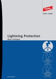
BLITZDUCTOR ® CT<br />
Lightning Current / Surge Arrester<br />
INFORMATION TECHNOLOGY SYSTEMS<br />
PLUGGABLE SPDs FOR DIN RAIL MOUNTING<br />
Testing<br />
SPDs more quickly and<br />
easily than ever!<br />
• Without contacting<br />
• In a second<br />
• At low costs<br />
Testing an SPD module with RFID system (LifeCheck)<br />
Regular testing of installed SPDs<br />
Multiple discharges with values beyond the specification of the device<br />
affected can overload surge arresters in telecommunications and signalling<br />
networks. To ensure a high system reliability, it is therefore recommendable<br />
to subject SPDs to systematic tests.<br />
IEC 62305-3 Ed. 1.0 [see Table] defines maintenance tests and test intervals<br />
for lightning protection systems. The maintenance programme should<br />
include the testing of SPDs designed for lightning equipotential bonding:<br />
Protection level Complete inspection Visual inspection<br />
I and II 2 years 1 year<br />
III, IV 4 years 2 years<br />
This table shall be considered generally a recommendation for lightning<br />
protection systems. For individual cases, however, these values can differ<br />
from the requirements of critical systems and specific directives (e.g.<br />
Regulations of the Nuclear Power Committee (KTA) for Lightning<br />
Protection of Nuclear Power Installations).<br />
Easy testing with LifeCheck<br />
Pluggable SPDs and corresponding test adapters can only be tested in a<br />
time-consuming way, as the SPD modules have to be removed, tested and<br />
then plugged in again. Moreover, the signal circuit is unprotected during<br />
the test. LifeCheck allows for quick and easy SPD testing. Removing the<br />
module is no longer required. Being integrated into the SPDs, the RFID<br />
system used requires no batteries or power supply. The proper condition<br />
of the SPD is constantly controlled. An extreme thermal or electrical load<br />
is detected reliably and can be registered with DEHNrecord DRC LC M1<br />
reader in a second and without contacting.<br />
Signal before damage<br />
The control device of the SPD is designed to generate a signal as soon as<br />
the SPD is threatened to be overloaded. This helps to take precautionary<br />
measures to avoid standstills within the installation.<br />
The control indicator system consists of two operating units:<br />
1. RFID Reader:<br />
This consists of a hand-held device with indicator and antenna. The<br />
reader transmits energy to the RFID transmission unit (transponder)<br />
within the SPD without contacting. This reads out the operating state<br />
and displays the same.<br />
2. Control unit within the SPD:<br />
This controls the protective circuit for impermissible overloads by<br />
thermal (overheating) or electrical (impulse currents) incidents. The<br />
control unit is connected directly with the transponder. If an overload<br />
is detected, the affected protection module has to be replaced.<br />
How does LifeCheck work<br />
SPD<br />
indication<br />
of operating<br />
state<br />
Transponder<br />
identification IC<br />
In order to provide a simple and clear indication, the LifeCheck circuit<br />
within the SPD was designed to ensure that the communication is interrupted<br />
whenever an overload has been detected. The actual indication is<br />
performed by DEHNrecord DRC LC M1 test device.<br />
Summary:<br />
RFID communication ok<br />
No RFID communication<br />
energy<br />
data<br />
= SPD ok<br />
= replace the SPD<br />
Reader<br />
reader IC<br />
power<br />
Principle of communication of an SPD with transponder and reader<br />
microcontroller<br />
communication<br />
2 www.dehn.de
INFORMATION TECHNOLOGY SYSTEMS<br />
PLUGGABLE SPDs FOR DIN RAIL MOUNTING<br />
BLITZDUCTOR ® CT<br />
Lightning Current / Surge Arrester<br />
The LifeCheck circuit within the SPD detects two types of overloads:<br />
1. Thermal overloads<br />
If the discharge elements are working in the critical temperature<br />
range, thermal fuse elements interrupt the RFID communication permanently.<br />
2. Electrical overloads<br />
If construction elements are threatened to be destroyed by peak<br />
overloads, the transponder interrupts the communication permanently.<br />
1<br />
2<br />
3<br />
4<br />
Overloaded SPD modules have to be replaced as soon as possible in<br />
order not to threaten the availability of the installation.<br />
Basic circuit diagram of a protective SPD circuit controlled by<br />
LifeCheck<br />
Combined Lightning Current and Surge<br />
Arrester Modules with LifeCheck ®<br />
for BLITZDUCTOR ® CT Base Parts<br />
BCT MLC B 110<br />
Lightning current arrester module with LifeCheck for nearly all types of<br />
applications. Generally in combination with downstream BCT MOD<br />
M... surge arresters.<br />
Type BCT MLC B 110<br />
SPD Class<br />
H<br />
Max. continuous dc voltage U C<br />
170 V<br />
Nominal current I L<br />
1 A<br />
D1 Total lightning impulse current (10/350 μs) I imp 5 kA<br />
PU Part<br />
Type pc(s) No.<br />
BCT MLC B 110 1 919 310<br />
BCT MLC BE 5 – BE 60<br />
Combined lightning current and surge arrester module with LifeCheck<br />
for protection of 2 single lines with common reference potential as<br />
well as unbalanced interfaces.<br />
Type BCT MLC ... BE 5 BE 12 BE 15 BE 24 BE 30 BE 48 BE 60<br />
SPD Class MMMMMMM<br />
Max. continuous dc<br />
voltage U C 6.0 V 14.5 V 17.8 V 26.8 V 34.8 V 55.1 V 70.1 V<br />
Nominal current I L 1 A 1 A 1 A 1 A 1 A 1 A 1 A<br />
D1 Total lightning impulse 5 kA 5 kA 5 kA 5 kA 5 kA 5 kA 5 kA<br />
current (10/350 μs) I imp<br />
PU Part<br />
Type pc(s) No.<br />
BCT MLC BE 5 1 919 320<br />
BCT MLC BE 12 1 919 321<br />
BCT MLC BE 15 1 919 322<br />
BCT MLC BE 24 1 919 323<br />
BCT MLC BE 30 1 919 324<br />
BCT MLC BE 48 1 919 325<br />
BCT MLC BE 60 1 919 326<br />
BCT MLC BE 110<br />
Combined lightning current and surge arrester module with LifeCheck<br />
for protection of 2 single lines with common reference potential as<br />
well as unbalanced interfaces.<br />
Type BCT MLC BE 110<br />
SPD Class<br />
L<br />
Max. continuous dc voltage U C<br />
170 V<br />
Nominal current I L<br />
1 A<br />
D1 Total lightning impulse current (10/350 μs) I imp 5 kA<br />
PU Part<br />
Type pc(s) No.<br />
BCT MLC BE 110 1 919 327<br />
BCT MLC BE C 5 – BE C 30<br />
Combined lightning current and surge arrester module with LifeCheck<br />
for protection of balanced interfaces with protective circuit for diodes<br />
at the input, for current loops (TTY) and optocoupler inputs.<br />
Type BCT MLC ... BE C 5 BE C 12 BE C 24 BE C 30<br />
SPD Class M M M M<br />
Max. continuous dc voltage U C 6.0 V 14.5 V 26.8 V 34.8 V<br />
Nominal current I L 0.1 A 0.1 A 0.1 A 0.1 A<br />
D1 Total lightning impulse current<br />
(10/350 μs) I imp 5 kA 5 kA 5 kA 5 kA<br />
PU Part<br />
Type pc(s) No.<br />
BCT MLC BE C 5 1 919 360<br />
BCT MLC BE C 12 1 919 361<br />
BCT MLC BE C 24 1 919 362<br />
BCT MLC BE C 30 1 919 363<br />
BCT MLC BD 5 – BD 60<br />
Combined lightning current and surge arrester module with LifeCheck<br />
for protection of balanced interfaces with electrical isolation.<br />
Type BCT MLC ... BD 5 BD 12 BD 15 BD 24 BD 30 BD 48 BD 60<br />
SPD Class MMMMMMM<br />
Max. continuous dc<br />
voltage U C 6.0 V 14.5 V 17.8 V 26.8 V 34.8 V 55.1 V 70.1 V<br />
Nominal current I L 1 A 1 A 1 A 1 A 1 A 1 A 1 A<br />
D1 Total lightning impulse 5 kA 5 kA 5 kA 5 kA 5 kA 5 kA 5 kA<br />
current (10/350 μs) I imp<br />
PU Part<br />
Type pc(s) No.<br />
BCT MLC BD 5 1 919 340<br />
BCT MLC BD 12 1 919 341<br />
BCT MLC BD 15 1 919 342<br />
BCT MLC BD 24 1 919 343<br />
BCT MLC BD 30 1 919 344<br />
BCT MLC BD 48 1 919 345<br />
BCT MLC BD 60 1 919 346<br />
BCT MLC BD 110 / BD 250<br />
Combined lightning current and surge arrester module with LifeCheck<br />
for protection of balanced interfaces with electrical isolation, telecommunications.<br />
Type BCT MLC BD 110 BCT MLC BD 250<br />
SPD Class L L<br />
Max. continuous dc voltage U C 170 V 280 V<br />
Nominal current I L 1 A 1 A<br />
D1 Total lightning impulse current (10/350 μs) I imp 5 kA 5 kA<br />
PU Part<br />
Type pc(s) No.<br />
BCT MLC BD 110 1 919 347<br />
BCT MLC BD 250 1 919 349<br />
www.dehn.de<br />
3
BLITZDUCTOR ® CT<br />
Lightning Current / Surge Arrester<br />
INFORMATION TECHNOLOGY SYSTEMS<br />
PLUGGABLE SPDs FOR DIN RAIL MOUNTING<br />
Combined Lightning Current and Surge<br />
Arrester Modules with LifeCheck ®<br />
for BLITZDUCTOR ® CT Base Parts<br />
BCT MLC BD HF<br />
Combined lightning current and surge arrester module with LifeCheck<br />
for protection of high-frequency bus systems or video transmissions.<br />
Type BCT MLC BD HF 5<br />
SPD Class<br />
M<br />
Max. continuous dc voltage U C<br />
6.0 V<br />
Nominal current I L<br />
0.1 A<br />
D1 Total lightning impulse current (10/350 μs) I imp 5 kA<br />
PU Part<br />
Type pc(s) No.<br />
BCT MLC BD HF 5 1 919 370<br />
BCT MLC BD HFD<br />
Combined lightning current and surge arrester module with LifeCheck<br />
for protection of high-frequency bus systems or telecommunications<br />
transmissions.<br />
LifeCheck ® SPD Test Unit<br />
For quick and contactless testing of SPDs with integrated LifeCheck<br />
control circuit. If the RFID chip is recognised in the module, a signal is<br />
generated. If the check-back signal of the RFID transmitting circuit<br />
within the SPD is not activated, the SPD has to be replaced.<br />
DRC LC M1<br />
Portable device with hand-held antenna for flexible use. Visual and<br />
acoustic ok indication of identified LifeCheck circuits in SPDs. To ensure<br />
safe positioning on the arrester modules BCT MLC, the hand-held antenna<br />
is designed as C shape unit. The enclosed test module is designed to<br />
be a testing reference and has to be identified by the DRC LC M1.<br />
Type<br />
DRC LC M1<br />
Measured value indication<br />
beeping tone and LED<br />
Testing time<br />
< 1 sec<br />
Delivery<br />
hand-held device, antenna for manual use, 9 V E block battery,<br />
test modules for reference, storage case<br />
PU Part<br />
Type pc(s) No.<br />
DRC LC M1 1 910 650<br />
Type BCT MLC BD HFD 5 BCT MLC BD HFD 24<br />
SPD Class M M<br />
Max. continuous dc voltage U C 6.0 V 26.8 V<br />
Nominal current I L 0.1 A 0.1 A<br />
D1 Total lightning impulse current<br />
(10/350 μs) I imp 5 kA 5 kA<br />
PU Part<br />
Type pc(s) No.<br />
BCT MLC BD HFD 5 1 919 371<br />
BCT MLC BD HFD 24 1 919 375<br />
Base Part for BLITZDUCTOR ® CT<br />
BCT BAS<br />
BLITZDUCTOR CT base part for use as universal feed-through<br />
terminal for supporting the SPD module without signal interruption.<br />
The SPD module is earthed safely by the supporting<br />
foot of the DIN rail with a snap-on device. Allows for direct or<br />
indirect shied earthing due to insert for gas discharge tubes.<br />
Type<br />
BCT BAS<br />
Cross-sectional area, solid<br />
0.08 - 4 mm 2 (shield)<br />
Cross-sectional area, flexible 0.08 - 2.5 mm 2<br />
Enclosure material polyamide PA 6.6<br />
PU Part<br />
Type pc(s) No.<br />
BCT BAS 1 919 506<br />
Available from<br />
DEHN + SÖHNE GmbH + Co.KG. • Hans-Dehn-Str. 1 • P. O. Box 1640 • 92306 Neumarkt • Germany<br />
www.dehn.de • export@dehn.de • Telephone +49 9181 906-462 • FAX +49 9181 906-444<br />
© Copyright 2006 DEHN + SÖHNE