no icing - depressurised standby function and ... - HL Hydraulik GmbH
no icing - depressurised standby function and ... - HL Hydraulik GmbH
no icing - depressurised standby function and ... - HL Hydraulik GmbH

Create successful ePaper yourself
Turn your PDF publications into a flip-book with our unique Google optimized e-Paper software.
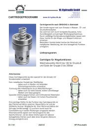
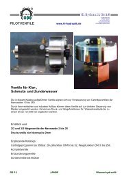
For high pressure air <strong>and</strong><br />
<strong>no</strong>n aggressive Medium for:<br />
- drying<br />
- de-oiling<br />
- filtering<br />
- Benefits<br />
- less corrosion<br />
- less wear<br />
- <strong>no</strong> <strong>icing</strong><br />
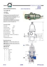
SCHRUPP<br />
GAS DRYER<br />
TYPE GTR<br />
<strong>and</strong> consequently<br />
- longer service life<br />
- lower maintenance costs<br />
- fail-safe operation<br />
P<br />
T<br />
A<br />
R<br />
www.hl-hydraulik.de<br />
<strong>HL</strong> <strong>Hydraulik</strong> <strong>GmbH</strong><br />
Kupferhütte 5c<br />
D-57562 Herdorf<br />
Tel 02744-9324-0<br />
Fax 02744-9324-56<br />
schrupp@hl-hydraulik.de<br />
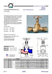
Ordering example: GTR 10 24GL 250<br />
Operating pressure 30-250 bar Type 250<br />
251-350 bar Type 350<br />
Voltage: 24GL = 24VGL<br />
220W = 220V50Hz<br />
E1.8.1 JAN09 HP-Pneumatic
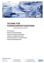
Technical Data<br />
Operating Pressure<br />
Flow Rate<br />
Regeneration Air<br />
Volume of Reservoir<br />
Max. Temperature<br />
Relative Humidity<br />
Voltage<br />
Power Consumption<br />
Baseplate Material<br />
Mounting Plate Material<br />
Reservoirs Material<br />
A <strong>and</strong> P Ports<br />
Weight<br />
SCHRUPP<br />
GAS DRYER<br />
TYPE GTR<br />
Part code Bracket<br />
GTR K 507335<br />
30 - 350 bar<br />
1000 L/min<br />
5-10% of Compressor<br />
0,7 cdm<br />
40°C<br />
100%<br />
24GL, 220W<br />
35W<br />
Brass / stainless steel<br />
Brass / stainless steel<br />
Steel Chem. Nickel Plates<br />
G 3/8“<br />
44 Kg<br />
Part code program control unit<br />
GTR PS 24GL (or 220W)<br />
R<br />
www.hl-hydraulik.de<br />
<strong>HL</strong> <strong>Hydraulik</strong> <strong>GmbH</strong><br />
Destination<br />
Symbol<br />
Designation<br />
Conn.<br />
No.<br />
1K1 7<br />
Terminal<br />
Strip<br />
X1<br />
Y3 A1 6 K1<br />
Y2 A1 5 K2<br />
Y1 A1 4 K2<br />
PE 3<br />
Y2 PE 3 Y3<br />
Y1 PE 3<br />
Y2 A2 2<br />
Kupferhütte 5c<br />
D-57562 Herdorf<br />
Tel 02744-9324-0<br />
Fax 02744-9324-56<br />
schrupp@hl-hydraulik.de<br />
Y1 A2 2 Y3<br />
L02 2 K1<br />
L01 1 K1<br />
Destination<br />
symbol<br />
E1.8.2 JAN09 HP-Pneumatic<br />
Designation<br />
Conn.<br />
No.<br />
A1<br />
34<br />
32<br />
PE<br />
A2<br />
A2<br />
15
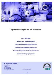
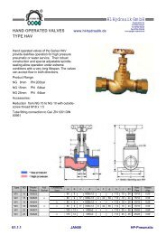
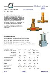
For compressed air <strong>and</strong> <strong>no</strong>n aggressive gaseous media<br />
drying de-oiling filtering<br />
this means<br />
less corrosion less wear <strong>and</strong> <strong>no</strong> <strong>icing</strong> during operation<br />
<strong>and</strong> therefore<br />
greater service life lower maaintenance costs<br />
The gasdrier consists of two reservoirs filled with highly<br />
porous hydrostatic materials (adsorbents), into which<br />
damp com-pressed air <strong>and</strong> dried depressurized air are<br />
alternately admitted for the regeneration phase.<br />
The inlet <strong>and</strong> outlet of the adsorbent reservoirs are each<br />
fitted with a sintered metal disk to filter the water <strong>and</strong> oil<br />
particles out <strong>and</strong> also any particles from the adsorbate material.<br />
Because of the modular design it is possible to flange up to<br />
three units togethe. The Basic unit includes all necassary<br />
directional, throttle <strong>and</strong> check valve funktions.<br />
The second <strong>and</strong> third untits include the additional adsorbent<br />
reservoirs to increase the capacity of the system.<br />
Technical Data:<br />
Operating pressure 40 – 350bar<br />
Regeneration air consumtion appr. 5%<br />
Flow rate per unit 1300 l/min<br />
750<br />
SCHRUPP<br />
GAS DRYER<br />
TYPE GTF<br />
R<br />
150 150 150 260<br />
www.hl-hydraulik.de<br />
<strong>HL</strong> <strong>Hydraulik</strong> <strong>GmbH</strong><br />
Kupferhütte 5c<br />
D-57562 Herdorf<br />
Tel 02744-9324-0<br />
Fax 02744-9324-56<br />
schrupp@hl-hydraulik.de<br />
E1.8.3 JAN09 HP-Pneumatic<br />
P
SCHRUPP<br />
GAS DRYER<br />
TYPE GTR<br />
SCHRUPP<br />
DRIER<br />
STATIONS<br />
For<br />
− drying<br />
− de-oiling<br />
− filtering<br />
compressed air <strong>and</strong> <strong>no</strong>n-<br />
aggressive gaseous media<br />
This means<br />
− less corrosion<br />
− less wear <strong>and</strong><br />
− <strong>no</strong> <strong>icing</strong><br />
during operation<br />
R<br />
www.hl-hydraulik.de<br />
<strong>and</strong> therefore<br />
− greater service life<br />
− lower maintenance costs <strong>and</strong><br />
− fail safe operation<br />
<strong>HL</strong> <strong>Hydraulik</strong> <strong>GmbH</strong><br />
Kupferhütte 5c<br />
D-57562 Herdorf<br />
Tel 02744-9324-0<br />
Fax 02744-9324-56<br />
schrupp@hl-hydraulik.de<br />
E1.8.4 JAN09 HP-Pneumatic
SCHRUPP<br />
GAS DRYER<br />
TYPE GTR<br />
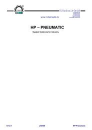
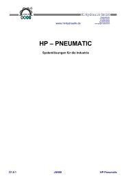
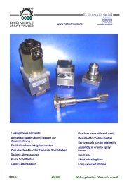
SCHRUPP GAS DRYER STATIONS<br />
Optional with Bypass<br />
For compressed Air <strong>and</strong> other<br />
<strong>no</strong>n aggresive gaseous media:<br />
- drying<br />
- de-oiling<br />
- filtering<br />
R<br />
this means<br />
- less corrosion<br />
- less wear <strong>and</strong><br />
- <strong>no</strong> <strong>icing</strong><br />
- <strong>depressurised</strong> <strong>st<strong>and</strong>by</strong> <strong>function</strong><br />
<strong>and</strong> therefore<br />
- greater service life<br />
- lower maintenance costs <strong>and</strong><br />
- fail save operation<br />
www.hl-hydraulik.de<br />
<strong>HL</strong> <strong>Hydraulik</strong> <strong>GmbH</strong><br />
Kupferhütte 5c<br />
D-57562 Herdorf<br />
Tel 02744-9324-0<br />
Fax 02744-9324-56<br />
schrupp@hl-hydraulik.de<br />
E1.8.6 JAN09 HP-Pneumatic
SCHRUPP<br />
GAS DRYER<br />
TYPE GTR<br />
Functional Description<br />
R<br />
The drier station consists of the gas drier, fine<br />
filter, pressure relief valve, pressure holding <strong>and</strong><br />
check valves <strong>and</strong> the electrical control unit.<br />
These components are mounted on a frame, pipe<br />
connected <strong>and</strong> wired ready for operation. The<br />
gas drier consists of two reservoirs filled with<br />
highly porous hydrostatic materials (adsorbents),<br />
into which damp com-pressed air <strong>and</strong> dried<br />
depressurized air are alternately admitted for the<br />
regeneration phase.<br />
The damp air coming from the compressor<br />
passes through the fine filter (6) <strong>and</strong> the<br />
energized open 3/2-way valve DN 6 (1.1), which<br />
voltage is being passed, <strong>and</strong> reaches the<br />
reservoir (1.5).<br />
www.hl-hydraulik.de<br />
The adsorbent in reservoir (1.5) removes the moisture from the damp compressed air as it passes through<br />
this reservoir. The <strong>no</strong>w dry air passes via the check valve (1.9), pressure holding valve (4) <strong>and</strong> check valve<br />
(5.1) to the storage vessel or to the consumer. A small portion of this dried compressed air is depressurized<br />
in the throttle valve (1.11) <strong>and</strong> flows through the check valve (1.8) to the reservoir (1.6). This dried air<br />
absorbs the water from the damp adsorbents <strong>and</strong> passes via the 3/2-way valve (1.2) into the atmosphere,<br />
thus regenerating the adsorbents.<br />
The inlet <strong>and</strong> outlet of the adsorbent reservoirs are each fitted with a sintered metal disk. These disks filter<br />
the water <strong>and</strong> oil particles out of the incoming damp air <strong>and</strong> any particles of adsorbate material from the<br />
outgoing air.<br />
Since drying <strong>and</strong> regeneration are performed in a counter-flow procedure, any residues are removed from<br />
the sintered metal disks at each reversal of the direction of flow.<br />
After the preset time interval (e.g. 10 minutes), the two 3/2-way valves (1.1 <strong>and</strong> 1.2) are automatically<br />
reversed via a timer switch.<br />
The procedure described above is <strong>no</strong>w repeated but with the reservoirs “reversed”.<br />
The drying procedure is connected to the operation of the compressor. When the compressor is switched<br />
off, both 3/2-way valves (1.1 <strong>and</strong> 1.2) are closed (off position).<br />
The pressure relief valve (7) opens <strong>and</strong> the condensate in the fine filter (6) is discharged.<br />
When the compressor is restarted, the frying procedure is continued where it was interrupted.<br />
<strong>HL</strong> <strong>Hydraulik</strong> <strong>GmbH</strong><br />
Using this method, extremely low pressure dew points can be achieved (depending on the operating<br />
pressure, down to –50°C <strong>and</strong> lower measured at the drier outlet).<br />
Kupferhütte 5c<br />
D-57562 Herdorf<br />
Tel 02744-9324-0<br />
Fax 02744-9324-56<br />
schrupp@hl-hydraulik.de<br />
E1.8.7 JAN09 HP-Pneumatic
SCHRUPP<br />
GAS DRYER<br />
TYPE GTR<br />
The drier station consists of:<br />
1 1 Gas drier Type GT 1000/250<br />
Max. operating pressure 45 bar<br />
Flow rate 1000 l/min<br />
Regeneration air 5-10% of compressor<br />
rating<br />
Control voltage AC or DC<br />
2 1 Electrical control unit Type 168 332<br />
with time lag switching-off<br />
3 1 Silencer Type 162 987<br />
4 1 Pressure holding valve Type V 501 b<br />
Set to (max. 45 bar)<br />
5 2 Check valves Type Ap 9308<br />
DN 15, PN 45<br />
6 1 Fine filter Type 450 688<br />
Capacity 0.65 liter<br />
7 1 2/2-way valve Type 500 004<br />
DN 6, PN 250<br />
Voltage 220 V, 50 Hz<br />
8 1 Mounting frame Type 169 286<br />
Installation, connection, bolts, cables, etc.<br />
All above components assembled, piped connected,<br />
wired <strong>and</strong> tested<br />
Product No. 169 300<br />
The drier station consists of:<br />
R<br />
1 1 Gas drier Type GT 1000/250<br />
Max. operating pressure 250 bar<br />
Flow rate 1000 l/min<br />
Regeneration air 5-10% of compressor<br />
rating<br />
Control voltage AC or DC<br />
2 1 Electrical control unit Type 168 332<br />
with time lag switching-off<br />
3 1 Silencer Type 162 987<br />
4 1 Pressure holding valve<br />
Set to (max. 250 bar)<br />
5 2 Check valves Type 450 050<br />
DN 8, PN 250<br />
6 1 Fine filter Type 450 688<br />
Capacity 0.65 liter<br />
7 1 2/2-way valve Type 500 004<br />
DN 6, PN 250<br />
Voltage 220 V, 50 Hz<br />
8 1 Mounting frame Type 450 738<br />
Installation, connection, bolts, cables, etc.<br />
All above components assembled, piped connected,<br />
wired <strong>and</strong> tested<br />
Product No. 169 460<br />
www.hl-hydraulik.de<br />
<strong>HL</strong> <strong>Hydraulik</strong> <strong>GmbH</strong><br />
Kupferhütte 5c<br />
D-57562 Herdorf<br />
Tel 02744-9324-0<br />
Fax 02744-9324-56<br />
schrupp@hl-hydraulik.de<br />
E1.8.8 JAN09 HP-Pneumatic
SCHRUPP<br />
GAS DRYER<br />
TYPE GTR<br />
R<br />
www.hl-hydraulik.de<br />
Destination<br />
Symbol<br />
<strong>HL</strong> <strong>Hydraulik</strong> <strong>GmbH</strong><br />
Terminal<br />
Strip<br />
Kupferhütte 5c<br />
D-57562 Herdorf<br />
Tel 02744-9324-0<br />
Fax 02744-9324-56<br />
schrupp@hl-hydraulik.de<br />
Destination<br />
symbol<br />
E1.8.9 JAN09 HP-Pneumatic<br />
Designation<br />
Conn.<br />
No.<br />
1K1 7<br />
X1<br />
Y3 A1 6 K1<br />
Y2 A1 5 K2<br />
Y1 A1 4 K2<br />
PE 3<br />
Designation<br />
Y2 PE 3 Y3<br />
Y1 PE 3<br />
Y2 A2 2<br />
Y1 A2 2 Y3<br />
L02 2 K1<br />
L01 1 K1<br />
Conn.<br />
No.<br />
A1<br />
34<br />
32<br />
PE<br />
A2<br />
A2<br />
15