HP â PNEUMATIC - HL Hydraulik GmbH
HP â PNEUMATIC - HL Hydraulik GmbH
HP â PNEUMATIC - HL Hydraulik GmbH

You also want an ePaper? Increase the reach of your titles
YUMPU automatically turns print PDFs into web optimized ePapers that Google loves.
SCHRUPP<br />
R<br />
www.hl-hydraulik.de<br />
<strong>HP</strong> – <strong>PNEUMATIC</strong><br />
System Solutions for Industry<br />
<strong>HP</strong> Pneumatic Valves<br />
<strong>HP</strong> Pneumatic Dryers<br />
<strong>HP</strong> Pneumatic Compressors<br />
<strong>HP</strong> Pneumatic Systems<br />
<strong>HL</strong> <strong>Hydraulik</strong> <strong>GmbH</strong><br />
Kupferhütte 5c<br />
D-57562 Herdorf<br />
Tel 02744-9324-0<br />
Fax 02744-9324-56<br />
schrupp@hl-hydraulik.de<br />
E1.0.1 JAN09 <strong>HP</strong>-Pneumatic
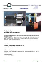
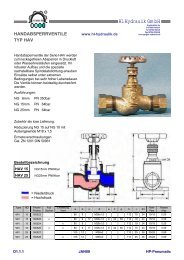
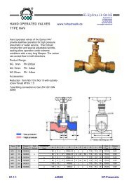
Hand operated valves of the Series HAV<br />
provide leakfree operation for high pressure<br />
pneumatic or water service. Their robust<br />
construction and special adjustable spindlesealing<br />
allow operation under extreme<br />
conditions with a very long lifespan. The valves<br />
can accept flow in both directions.<br />
Product Range:<br />
NG 8mm PN 200bar<br />
NG 15mm PN 64bar<br />
NG 25mm PN 64bar<br />
Accessories:<br />
SCHRUPP<br />
HAND OPERATED VALVES<br />
TYPE HAV<br />
Reduction from NG 15 to NG 10 with outsidescrew<br />
thread M18 x 1.5<br />
Tube fitting connection to Gal. ZN 1201 DIN<br />
50961<br />
Type<br />
ND<br />
Prodnr<br />
Prodno<br />
R<br />
Fuß<br />
Socket<br />
Entlastung<br />
Vent<br />
www.hl-hydraulik.de<br />
<strong>HL</strong> <strong>Hydraulik</strong> <strong>GmbH</strong><br />
a b c d e f g h i S1<br />
Kupferhütte 5c<br />
D-57562 Herdorf<br />
Tel 02744-9324-0<br />
Fax 02744-9324-56<br />
schrupp@hl-hydraulik.de<br />
HAV 15 160523 80 9 M26x1,5 112 19 24 15/18 0,55<br />
HAV 15 160525 x 80 9 17 M26x1,5 8 44 60 112 19 24 15/18 0,59<br />
HAV 15 160524 x 80 9 M26x1,5 112 19 24 15/18 0,55<br />
HAV 15 160526 x x 80 9 17 M26x1,5 8 44 60 112 19 24 15/18 0,59<br />
HAV 25 160527 105 12 M36x2 113 25 36 25/28 0,89<br />
HAV 25 160528 x 105 12 M26x2 113 25 36 25/28 0,89<br />
E1.1.1 JAN09 <strong>HP</strong>-Pneumatic<br />
Rohr<br />
Pipe<br />
Masse<br />
(Kg)
Order-Information HAV 08 Pno.: 504242<br />
NG 8mm PN 350bar<br />
Product Nr: 504242<br />
Spare parts kit<br />
Consisting of:<br />
Pos Name<br />
1 O – Ring (u-ring)<br />
3 Disk<br />
SCHRUPP<br />
HAND OPERATED VALVES<br />
TYPE HAV<br />
4 Seal Kit<br />
Order Information<br />
HAV 15 VTS<br />
HAV 25 VTS<br />
R<br />
www.hl-hydraulik.de<br />
<strong>HL</strong> <strong>Hydraulik</strong> <strong>GmbH</strong><br />
Kupferhütte 5c<br />
D-57562 Herdorf<br />
Tel 02744-9324-0<br />
Fax 02744-9324-56<br />
schrupp@hl-hydraulik.de<br />
Accessories<br />
HAV 08<br />
Tube fitting Connection per: Gal. ZN 1201 DIN 50961 for<br />
tube D = 8/12mm<br />
Order nr: HAV 08 EOV<br />
HAV Tube fitti ng Connection per: Gal. ZN<br />
1201 DIN 50961 for tube D = 15/18mm<br />
Order nr: HAV 15 EOV<br />
Reduction from M26x1.5 to M18x1.5 thread<br />
Order nr.: HAV 15 RED10<br />
HAV 25<br />
Tube fitting Connection per: Gal. ZN 1201 DIN 50961 for<br />
tube D = 25/28mm<br />
Order nr.: HAV 25 EOV<br />
E1.1.2 JAN09 <strong>HP</strong>-Pneumatic
NP 64bar<br />
ND 15 and ND 25mm<br />
Complete with EO fittings<br />
Gal. ZN 1201 DIN 50961<br />
ND Seat a b c d Mass Partno.<br />
15 soft M26 x 1,5 9 80 60 0,4 Kg 160535<br />
25 soft M36 x 2 12 105 58 0,5 Kg 160537<br />
Ordering code and example:<br />
Type, Size, Pressure<br />
RSV 15 – 64<br />
Pressure difference for opening 2bar<br />
NP 100<br />
SCHRUPP<br />
NON RETURN VALVES<br />
TYPE RSV<br />
ND10 NP200 and ND25 NP100<br />
Complete with EO fittings<br />
Gal. ZN 1201 DIN 50961<br />
ND Connection length<br />
10 M 20 x 1,5 80<br />
25 M 36 x 2 85<br />
Ordering code and example:<br />
Type, Size, Pressure<br />
RSV 10 – 200<br />
R<br />
www.hl-hydraulik.de<br />
<strong>HL</strong> <strong>Hydraulik</strong> <strong>GmbH</strong><br />
Kupferhütte 5c<br />
D-57562 Herdorf<br />
Tel 02744-9324-0<br />
Fax 02744-9324-56<br />
schrupp@hl-hydraulik.de<br />
E1.2 JAN09 <strong>HP</strong>-Pneumatic
SCHRUPP<br />
PRESSURE MAINTAINING<br />
VALVES TYPE HAV<br />
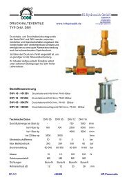
Pressure Maintaining and Pressure<br />
Maintaining Check Valves series DHV and<br />
DRV are mounted between the condenser<br />
and the compressed air vessel. These<br />
valves maintain a constant pressure at the<br />
condenser and help to facilitate water<br />
separation from the air.<br />
The higher the pressure at the valve, the<br />
better the water-separation.<br />
Their robust construction allows their use<br />
under extreme conditions with a very long<br />
lifespan.<br />
Ordering Information<br />
R<br />
www.hl-hydraulik.de<br />
<strong>HL</strong> <strong>Hydraulik</strong> <strong>GmbH</strong><br />
DHV 16 - 451263 Pressure Maintaining Valve NG16mm PN15-60bar<br />
DHV 12 - 451262 Pressure Maintaining Valve NG12mm PN60-350bar<br />
DHV 05 - 504270 Pressure Maintaining Valve NG 5mm PN60-350bar<br />
DRV 05 - 450050 Pressure Maintaining Check Valve NG 5mm PN60-350bar<br />
Technical Data DHV 05 DRV 05 DHV 12 DHV 16<br />
Flow rate with 5bar dp - - 750 1500 l/min<br />
with 10bar dp 160 160 2500 5000 l/min<br />
with 15bar dp 4600 9200 l/min<br />
with 220 bar dp 3500 3500 l/min<br />
Minimum pressure difference 10 10 5 5 bar<br />
Max. Working pressure 350 350 350 60 bar<br />
Pressure range 60-350 60-350 30-350 15-60 bar<br />
Mass 10 18 120 120 N<br />
Hous ing material MS MS MS MS<br />
Seals Buna -N Buna -N Buna -N Buna -N<br />
Tube-connection size 12 12 20 28 mm<br />
Kupferhütte 5c<br />
D-57562 Herdorf<br />
Tel 02744-9324-0<br />
Fax 02744-9324-56<br />
schrupp@hl-hydraulik.de<br />
E1.3.1 JAN09 <strong>HP</strong>-Pneumatic
SCHRUPP<br />
PRESSURE MAINTAINING<br />
VALVES TYPE HAV<br />
DHV 16<br />
28 (25 option)<br />
R<br />
www.hl-hydraulik.de<br />
Bestellnr. Dichtsatz / Orderno. seal kit: DHV 16 - VTS - 451263 - 92<br />
80<br />
120<br />
202<br />
Einstellung des Öffnungsdruckes<br />
Opening Pressure Adjustment<br />
Befestigungslöcher<br />
Fixing Holes M8<br />
<strong>HL</strong> <strong>Hydraulik</strong> <strong>GmbH</strong><br />
Kupferhütte 5c<br />
D-57562 Herdorf<br />
Tel 02744-9324-0<br />
Fax 02744-9324-56<br />
schrupp@hl-hydraulik.de<br />
DHV 16<br />
E1.3.2 JAN09 <strong>HP</strong>-Pneumatic<br />
60<br />
300<br />
30<br />
75
SCHRUPP<br />
PRESSURE MAINTAINING<br />
VALVES TYPE HAV<br />
DHV 12<br />
20<br />
R<br />
www.hl-hydraulik.de<br />
Bestellnr. Dichtsatz / Orderno. seal kit: DHV 12 - VTS - 451262 - 92<br />
80<br />
120<br />
202<br />
Einstellung des Öffnungsdruckes<br />
Opening Pressure Adjustment<br />
Befestigungslöcher<br />
Fixing Holes M8<br />
<strong>HL</strong> <strong>Hydraulik</strong> <strong>GmbH</strong><br />
Kupferhütte 5c<br />
D-57562 Herdorf<br />
Tel 02744-9324-0<br />
Fax 02744-9324-56<br />
schrupp@hl-hydraulik.de<br />
E1.3.3 JAN09 <strong>HP</strong>-Pneumatic<br />
30<br />
60<br />
330<br />
30<br />
75
SCHRUPP<br />
PRESSURE MAINTAINING<br />
VALVES TYPE HAV<br />
R<br />
www.hl-hydraulik.de<br />
<strong>HL</strong> <strong>Hydraulik</strong> <strong>GmbH</strong><br />
Ordering Information<br />
Spare parts kit<br />
DHV 05 VTS<br />
Ordering Information<br />
Spare parts kit<br />
DRV 05 VTS<br />
Kupferhütte 5c<br />
D-57562 Herdorf<br />
Tel 02744-9324-0<br />
Fax 02744-9324-56<br />
schrupp@hl-hydraulik.de<br />
DHV 05<br />
DRV 05<br />
E1.3.4 JAN09 <strong>HP</strong>-Pneumatic
Pressure Maintaining Valves are mounted between the condenser and the compressed air vessel. These valves<br />
maintain a constant pressure at the condenser and help to facilitate water separation from the air.<br />
The higher the pressure at the valve, the better the water-separation.<br />
Pressure Maintaining Valve comlplete with EO fittings GAL. ZN 1201 DIN 50961<br />
Size: 8mm Ordering Code and Example Sealing kit<br />
Seat: soft Type, Size, Pressure, Order Pnr. No:<br />
Mass: 0,5Kg DHV 08 - 45 - 160540<br />
DHV08 VTS<br />
Max Pressure: 45bar<br />
Example:<br />
SCHRUPP<br />
PRESSURE MAINTAINING<br />
VALVES TYPE HAV<br />
Valve combination DMV 08 and<br />
DHV 08. This combination can<br />
be used to reduce a pressure<br />
in a system and to protect the<br />
secondary circuit against<br />
overpressure.<br />
R<br />
www.hl-hydraulik.de<br />
<strong>HL</strong> <strong>Hydraulik</strong> <strong>GmbH</strong><br />
1 O-Ring<br />
2 O-Ring<br />
3 O-Ring<br />
4 Seal 13 x 3<br />
Kupferhütte 5c<br />
D-57562 Herdorf<br />
Tel 02744-9324-0<br />
Fax 02744-9324-56<br />
schrupp@hl-hydraulik.de<br />
E1.3.5 JAN09 <strong>HP</strong>-Pneumatic
SCHRUPP<br />
SAFETY VALVES<br />
TYPE SVE06<br />
R<br />
www.hl-hydraulik.de<br />
SAFETY VALVE TYPE V600<br />
ORDERINGNO SVE06 - 87202<br />
Application: Schrupp safety valves type<br />
SV06-1 and SV06-2 are spring loaded<br />
valves designed to protect compressors<br />
from over-pressurization.<br />
The Schrupp safety valves can also be<br />
used to protect pressure vessels<br />
containing non-poisonous gases.<br />
Special characteristics: TUV approval up to 350 bar<br />
Acc. To 97/23/EC, Group 2, Div IV<br />
Low hysteresis and good operational control even under<br />
adverse conditions.<br />
Compact design<br />
Robust design<br />
Easy to maintain<br />
Technical Data: DN6 Opening Pressure: Type SV06-1 Pressure range 150 -350bar<br />
350 bar<br />
Type SV06-2 Pressure range 55 - 150bar<br />
150 bar<br />
Flow rate(liters/min) = 32.2 x pressure(bar)<br />
Ambient Temperature: 0-70 degrees C.<br />
proportional safety valve, mass 1,3kg.<br />
<strong>HL</strong> <strong>Hydraulik</strong> <strong>GmbH</strong><br />
Kupferhütte 5c<br />
D-57562 Herdorf<br />
Tel 02744-9324-0<br />
Fax 02744-9324-56<br />
schrupp@hl-hydraulik.de<br />
Notice: Valves are shipped with plugged ports. Please remove<br />
before installation<br />
E1.4.1 JAN09 <strong>HP</strong>-Pneumatic
Set Pressure<br />
SCHRUPP<br />
SAFETY VALVES<br />
TYPE SVE06<br />
Spare parts kit numbe: SVE 06 VTS 87202-92<br />
Mark Number Description<br />
5 Seat<br />
15 O-ring<br />
16 O-ring<br />
18 Back up ring<br />
R<br />
Functional Description: Port R is<br />
connected to the compressor or high<br />
pressure vessel. In the event of overpressure,<br />
the ball lifts from the seat and<br />
bleeds pressure through the side outlet port.<br />
The elbow fittings can be arranged to send<br />
the air in any direction. To check valve<br />
function, turn lever #21 counter-clockwise<br />
to valve housing, #1. This test will not<br />
affect the pressure set point.<br />
The set pressure can be adjusted by turning<br />
lever #21 after loosening locking nut #20.<br />
(Turn clockwise to increase pressure set<br />
point.) After adjustment, re-tighten locking<br />
nut #20. The valves do not require regular<br />
servicing. Periodically, tests are required.<br />
according to 97/23EC.<br />
Note: The set pressure for type SV06 can be adjusted in the range as shown below:<br />
On request, the adjustment can be made by TUV or on the Schrupp test stand.<br />
SV06<br />
Set pressure in bar Set pressure in bar<br />
150 - 175 55 - 66<br />
175.1 – 220 66.1 – 85<br />
220.1 - 350 85.1 – 110<br />
110.1 – 135<br />
135.1 - 150<br />
www.hl-hydraulik.de<br />
Ordering example<br />
SVE 06 - 55-66 - 87202<br />
Type<br />
Pressure set point<br />
<strong>HL</strong> <strong>Hydraulik</strong> <strong>GmbH</strong><br />
Kupferhütte 5c<br />
D-57562 Herdorf<br />
Tel 02744-9324-0<br />
Fax 02744-9324-56<br />
schrupp@hl-hydraulik.de<br />
E1.4.2 JAN09 <strong>HP</strong>-Pneumatic
SCHRUPP<br />
SAFETY VALVES (POP OFF)<br />
TYPE SVE30<br />
R<br />
Technical Data: Nominal Size: Dn 30<br />
Set pressure from 4.5 to 44 bar<br />
Flow rate: 4750 – p in liter/min<br />
Weight: approximately 3.2 kg<br />
SVE30<br />
Pressure [bar]<br />
4.5<br />
6.1<br />
8.1<br />
13.1<br />
18.1<br />
21.1<br />
25.1<br />
30.1<br />
35.1<br />
41.1<br />
- 41.1-44 - 89062<br />
-<br />
-<br />
-<br />
-<br />
-<br />
-<br />
-<br />
-<br />
-<br />
-<br />
6<br />
8<br />
13<br />
18<br />
21<br />
25<br />
30<br />
35<br />
41<br />
44<br />
www.hl-hydraulik.de<br />
<strong>HL</strong> <strong>Hydraulik</strong> <strong>GmbH</strong><br />
Kupferhütte 5c<br />
D-57562 Herdorf<br />
Tel 02744-9324-0<br />
Fax 02744-9324-56<br />
schrupp@hl-hydraulik.de<br />
Safety Valves Type S650:<br />
Orderingno. SVE 30<br />
Application: The Schrupp SV30 safety<br />
valve is a spring loaded valve used to<br />
protect vessels containing non-toxic gases<br />
from over-pressurization. Upon reaching<br />
the set pressure, the valve opens fully and<br />
immediately.<br />
Special Features: Pilot operation<br />
According to 97/23/EC<br />
Robust design<br />
Low hysteresis<br />
Excellent control even under adverse<br />
conditions<br />
Easy to maintain and install<br />
Accessory: reducer to NG 15<br />
Model number: SVE30 RED 15 - 89062-92<br />
E1.4.3 JAN09 <strong>HP</strong>-Pneumatic
3. Adjustment of<br />
Set Pressure<br />
4. Noise<br />
protection<br />
After removing the pin the set pressure<br />
can be changed, by turning the thread<br />
cap clockwise (increases set pressure)<br />
or counter-clockwise (reduces set<br />
pressure).<br />
Because of the possible production of high<br />
noise levels, we recommend the use of<br />
an ear protection.<br />
Spare parts kit Part Qty Designation<br />
Order No.<br />
SVE 30 VTS<br />
Mode of operation:<br />
Open:<br />
SCHRUPP<br />
SAFETY VALVES (POP OFF)<br />
TYPE SVE30<br />
R<br />
4 1 Piston<br />
5 1 Compression spring<br />
6 1 O-Ring<br />
8 1 Torsion spring<br />
13 1 Seal 45/58 x1<br />
15 1 Valve insert<br />
25 1 O-Ring<br />
26 1 Seal 30/39 X 5<br />
With increasing pressure the valve insert (15) rises<br />
out of its seat and vents air to atmosphere. Then the<br />
piston (4) rises out of its seat and the valve opens.<br />
Closing: After blowing the pressure off over the piston (4) the<br />
valve insert (15) closes fast; the closing process of<br />
the piston (4) is delayed until the pressure build-up<br />
over the piston (4) escapes through the drilling in the<br />
piston. Thus, closing of the piston (4) takes place not<br />
via the strength of the spring (5), but with the<br />
pressure on the differential area of the piston (4)<br />
opposite the valve seat.<br />
www.hl-hydraulik.de<br />
Maintenance and Operation:<br />
1. Shipping<br />
1. Shipping<br />
and<br />
and<br />
Storage<br />
Storage<br />
2. Installation<br />
<strong>HL</strong> <strong>Hydraulik</strong> <strong>GmbH</strong><br />
Kupferhütte 5c<br />
D-57562 Herdorf<br />
Tel 02744-9324-0<br />
Fax 02744-9324-56<br />
schrupp@hl-hydraulik.de<br />
During transportation or storage, the valve should be<br />
locked in the open position by use of the manual handle.<br />
All ports must be plugged. To open the valve, the lever<br />
should be moved against the spring force to the end<br />
position and fixed by the holding clamp.<br />
On pressure vessels or pipes with minimum inside<br />
diameter of 1 inch. For installation, use only original<br />
seals; never use glue or other additional seal<br />
materials.<br />
E1.4.4 JAN09 <strong>HP</strong>-Pneumatic
SCHRUPP<br />
SAFETY VALVES<br />
TYPE SVE 10<br />
Teilenr. Anschluß<br />
Partno. Connection<br />
R<br />
Sicherheitsventil für Druckluft mit Baumusterprüfung.<br />
TÜV approved Safety Valve for compressed air.<br />
97/23/EC, Gruppe2, KategorieIV<br />
Einstelldruck / Set Pressure: 0,3 – 50 bar<br />
Betriebstemperatur / Operating Temperature: max 180°C<br />
DN: 10mm<br />
Bestellbeispiel / Ordering Example<br />
SVE10 - G1/2 - 45 - Teilenr<br />
Druckbereich<br />
Pressure<br />
www.hl-hydraulik.de<br />
SW A C D<br />
850803 G3/8” 0,3 – 8,5 bar 27 22 75 12<br />
850803<br />
8,6 – 40 bar 27 22 95 12<br />
850803<br />
40,1– 50 bar 27 22 120 12<br />
850804 G1/2” 0,3 – 8,5 bar 27 26 75 14<br />
850804<br />
8,6 – 40 bar 27 26 95 14<br />
850804<br />
40,1– 50 bar 27 26 120 14<br />
850805 G3/4“ 0,3 – 8,5 bar 32 32 75 16<br />
850805<br />
8,6 – 40 bar 32 32 95 16<br />
850805<br />
40,1– 50 bar 32 32 120 16<br />
Dimensions in mm<br />
<strong>HL</strong> <strong>Hydraulik</strong> <strong>GmbH</strong><br />
Kupferhütte 5c<br />
D-57562 Herdorf<br />
Tel 02744-9324-0<br />
Fax 02744-9324-56<br />
schrupp@hl-hydraulik.de<br />
Einstelldruck / Set Pressure<br />
Anschluß/Connection<br />
Type<br />
E1.4.5 JAN09 <strong>HP</strong>-Pneumatic<br />
D C<br />
SW<br />
A
Safety devices of the type SHE are used to protect<br />
downstream storage vessels which are being fed by a<br />
higher operating pressure, against over pressurization.<br />
As opposed to the function of a typical safety valve, the<br />
Schrupp SHE valve protects the lower rated pressure<br />
vessel by closing the interconnection between the two<br />
vessels once the set pressure has been reached. In<br />
this way, the operational (low pressure) vessel is<br />
protected, while at the same time, maintaining the<br />
stored pressurized air necessary to ensure operation of<br />
the selected component, such as electrical switch gear.<br />
The Schrupp SHE safety device includes the following<br />
elements:<br />
a. Locking valve with electrical position indication<br />
switch.<br />
b. Solenoid actuated, pilot operated, 2/2 way sluice<br />
valve.<br />
c. Throttling Device.<br />
d. Pressure Relief Valve<br />
e. Pilot Throttle.<br />
f. Bleed Valve.<br />
High pressure<br />
storage vessel<br />
P<br />
a<br />
c<br />
SCHRUPP<br />
SAFETY DEVICES<br />
TYPE SHE<br />
S ST<br />
Low pressure operating vessel<br />
e<br />
R<br />
b<br />
f<br />
d<br />
www.hl-hydraulik.de<br />
Technical Data<br />
<strong>HL</strong> <strong>Hydraulik</strong> <strong>GmbH</strong><br />
Kupferhütte 5c<br />
D-57562 Herdorf<br />
Tel 02744-9324-0<br />
Fax 02744-9324-56<br />
schrupp@hl-hydraulik.de<br />
TYPE SHE 06 SHE 20<br />
Nominal size 20 10 mm<br />
Primary pressure 64 64 - 200 bar<br />
Secondary pressure 5 – 40 15 – 40 bar<br />
Max flow rate 56,000 56,000 l/min<br />
Mass ca. 320 ca. 320 N<br />
Nominal size of 6 6 mm<br />
pressure relief valve<br />
Port P M36 x 2 G 3/8“<br />
Port T M36 x 2 M36 x 2<br />
Port ST connection for 10<br />
pipes with outside<br />
dimension:<br />
According to 97/23/EC<br />
10 mm<br />
E1.5.1 JAN09 <strong>HP</strong>-Pneumatic
SCHRUPP<br />
SAFETY DEVICES<br />
TYPE SHE<br />
R<br />
www.hl-hydraulik.de<br />
<strong>HL</strong> <strong>Hydraulik</strong> <strong>GmbH</strong><br />
Kupferhütte 5c<br />
D-57562 Herdorf<br />
Tel 02744-9324-0<br />
Fax 02744-9324-56<br />
schrupp@hl-hydraulik.de<br />
E1.5.2 JAN09 <strong>HP</strong>-Pneumatic
SCHRUPP<br />
SAFETY DEVICES<br />
TYPE SHE<br />
Ordering code<br />
SHE 06 24GL<br />
Voltage 24v DC = 24GL =24GL<br />
240v/60Hz = 240W<br />
,,, Inlet pressure up to 64 bar = 064<br />
,,,Inlet pressure up to 200 bar = 200<br />
Spare parts kit: SHE 06 24GL VTS<br />
R<br />
www.hl-hydraulik.de<br />
Port Connections<br />
<strong>HL</strong> <strong>Hydraulik</strong> <strong>GmbH</strong><br />
SHE 06 P,T - M36 x 2<br />
St - 10 mm<br />
SHE 20 P - G 3/8”<br />
T - M36 x 2<br />
St - 10 mm<br />
Kupferhütte 5c<br />
D-57562 Herdorf<br />
Tel 02744-9324-0<br />
Fax 02744-9324-56<br />
schrupp@hl-hydraulik.de<br />
E1.5.3 JAN09 <strong>HP</strong>-Pneumatic
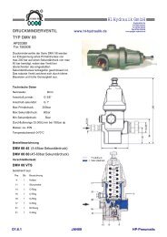
SCHRUPP<br />
Schrupp pressure reducing valves,<br />
type DMV08 are used to reduce<br />
pneumatic system pressure from a<br />
maximum primary pressure of 200<br />
bar to a maximum secondary<br />
pressure of 60 bar. Upon reaching<br />
the adjusted outlet pressure, the<br />
leakfree Schrupp DMV08 closes. The<br />
robust design of the Schrupp<br />
pressure reducing valve is very<br />
compact and provides exact pressure<br />
control.<br />
Technical Data<br />
Nominal Size: 8mm<br />
Inlet port: G 3/8“<br />
Outlet port: G 1“<br />
Max Primary pressure: 200bar<br />
Max Secondary pressure: 60bar<br />
Min Secondary pressure: 5bar<br />
Flow rate 33,000L/min at 180bar dp<br />
Mass: ca. 45N<br />
Ambient Temperature 0-70°C<br />
Ordering Code<br />
DMV 08 45 (5-45bar Primary press.)<br />
DMV 08 60 (45-60bar Primary press.)<br />
Spare Parts Kit<br />
DMV 08 VTS<br />
includes:<br />
Pos Stk Description<br />
4 1 Piston<br />
11 1 Seat Ring<br />
14 1 O-Ring<br />
15 1 O-Ring<br />
16 1 O-Ring<br />
17 1 O-Ring<br />
21 1 Seal<br />
31 1 O-Ring<br />
R<br />
PRESSURE REDUCING VALVE<br />
TYPE DMV 08<br />
AP20380<br />
Pno.155308<br />
www.hl-hydraulik.de<br />
<strong>HL</strong> <strong>Hydraulik</strong> <strong>GmbH</strong><br />
Kupferhütte 5c<br />
D-57562 Herdorf<br />
Tel 02744-9324-0<br />
Fax 02744-9324-56<br />
schrupp@hl-hydraulik.de<br />
E1.6.1 JAN09 <strong>HP</strong>-Pneumatic
SCHRUPP<br />
Schrupp pressure reducing valves, type<br />
DMV20 are used to reduce pneumatic system<br />
pressure from a maximum primary pressure of<br />
40 bar to a maximum secondary pressure of<br />
25 bar. Upon reaching the adjusted outlet<br />
pressure, the leakfree Schrupp DMV20 closes.<br />
The robust design of the Schrupp pressure<br />
reducing valve is very compact and provides<br />
exact pressure control.<br />
Technical Data<br />
Size: 20mm<br />
Inlet port: G 1“<br />
Outlet port: G 1“<br />
Max inlet-pressure: 40bar<br />
Max outlet-pressure: 25bar<br />
Min outlet pressure: 0,5bar<br />
Flowrate 7.800L/min max<br />
Mass: apr. 4Kg<br />
Temperature 0-60°C<br />
Ordering code<br />
DMV 20 - 453419<br />
R<br />
PRESSURE REDUCING VALVE<br />
TYPE DMV 20<br />
www.hl-hydraulik.de<br />
<strong>HL</strong> <strong>Hydraulik</strong> <strong>GmbH</strong><br />
Kupferhütte 5c<br />
D-57562 Herdorf<br />
Tel 02744-9324-0<br />
Fax 02744-9324-56<br />
schrupp@hl-hydraulik.de<br />
E1.6.2 JAN09 <strong>HP</strong>-Pneumatic
SCHRUPP<br />
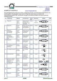
SLUICE OR DIRECTIONAL<br />
VALVES TYPE WEV<br />
These directional control valves are used to<br />
channel air from a high pressure reservoir<br />
to operationsl vessels with a lower<br />
pressure. The Schrupp sluice valves are<br />
direct solenoid operated 2/2 way valve size<br />
NG6 (3/8“) or can be combined with our<br />
leak free cartridge assembly for larger<br />
sizes. In combination with other devices<br />
including pressure reducing valves, relief or<br />
safety valves, filters, throttles, etc., the<br />
Schrupp WEV series valves can be used<br />
for multiple applications in a high pressure<br />
pneumatic system.<br />
A<br />
B C<br />
R<br />
Type WEV 06 - 500002<br />
Materials Stainless Steel, Brass<br />
Technical<br />
Data<br />
www.hl-hydraulik.de<br />
Pressure Range 0-400bar<br />
Nominal Size DN6<br />
Surface temperature -20 to +80°C<br />
Ambient temperature max 45°C<br />
Medium Gas<br />
Flow range see diagram<br />
Voltage Gas 12 - 240v ac/dc<br />
Max power consumtion see Diagram 42 W<br />
I.D. 12-240V 100% ac/dc<br />
Protection class IP65, Nema 4<br />
Consumption 42W<br />
opening and closing 1 time (water)<br />
Q = 25 l/min 1sec<br />
Q = 42 l/min IP 65,3 3sec se Nema 4<br />
Voltage<br />
Tolerance<br />
+5 to –10%<br />
Opening and closing time in<br />
water<br />
Q = 25 l/min 1 sec<br />
Q = 45 l/min 3 sec<br />
<strong>HL</strong> <strong>Hydraulik</strong> <strong>GmbH</strong><br />
Kupferhütte 5c<br />
D-57562 Herdorf<br />
Tel 02744-9324-0<br />
Fax 02744-9324-56<br />
schrupp@hl-hydraulik.de<br />
E1.7.1 JAN09 <strong>HP</strong>-Pneumatic
ORDERCODE<br />
TYPE: WEV 06 P250 500002 024G 24V DC<br />
110W 110V/50Hz (60Hz)<br />
220W 220V/50Hz (60Hz)<br />
Pressure-range up to 50, 250, 400bar<br />
Dimensions<br />
SCHRUPP<br />
SLUICE OR DIRECTIONAL<br />
VALVES TYPE WEV<br />
A<br />
B C<br />
R<br />
179<br />
www.hl-hydraulik.de<br />
4xM8 max D6<br />
A1<br />
B C<br />
A2<br />
D 40<br />
D 60<br />
60<br />
B A C<br />
71<br />
73 180<br />
<strong>HL</strong> <strong>Hydraulik</strong> <strong>GmbH</strong><br />
Kupferhütte 5c<br />
D-57562 Herdorf<br />
Tel 02744-9324-0<br />
Fax 02744-9324-56<br />
schrupp@hl-hydraulik.de<br />
E1.7.2 JAN09 <strong>HP</strong>-Pneumatic
These directional control valves are used to<br />
channel air from a high pressure reservoir to<br />
operationsl vessels with a lower pressure.<br />
The Schrupp sluice valves are direct solenoid<br />
operated 2/2 way valve size NG6 (3/8“) or can<br />
be combined with our leak free cartridge<br />
assembly for larger sizes. In combination with<br />
other devices including pressure reducing<br />
valves, relief or safety valves, filters, throttles,<br />
etc., the Schrupp WEV series valves can be<br />
used for multiple applications in a high<br />
pressure pneumatic system.<br />
Type WEV 06 R<br />
Materials Stainless Steel, Brass<br />
Technical Data<br />
Functional<br />
Description<br />
Pressure Range<br />
Nominal Size<br />
Surface Temperature<br />
Ambient Temperature<br />
Medium<br />
Flow Renge<br />
Voltages<br />
Max. Power<br />
Consumption I.D.<br />
Electrical Protection<br />
Class<br />
Voltage Tolerance<br />
Spare Parts WEV 06 R<br />
Item<br />
3<br />
4<br />
5<br />
6<br />
7<br />
8<br />
Quantity<br />
1<br />
1<br />
2<br />
4<br />
6<br />
2<br />
SCHRUPP<br />
SLUICE OR DIRECTIONAL<br />
VALVES TYPE WEV<br />
R<br />
0-250bar<br />
DN6<br />
-20 to+80°C<br />
max 45°C<br />
Gas<br />
see Diagram<br />
12-240V ac/dc<br />
43W<br />
100%<br />
IP 65, Nema 4<br />
+5 to –10%<br />
When solenoid 1 is de-energized, spring 9<br />
pushes the piston against seat 8a. Port 1<br />
is blocked, port 2 is connected to port 3.<br />
When solenoid 1 is energized, the piston<br />
will be shifted against seat 8b. Port 2 is<br />
blocked and port 1 is connected to port 3.<br />
Description<br />
Seal<br />
Rd-Ring<br />
Turcon Step seal<br />
Rd-Ring<br />
Back up ring<br />
Valve Seat<br />
www.hl-hydraulik.de<br />
<strong>HL</strong> <strong>Hydraulik</strong> <strong>GmbH</strong><br />
Kupferhütte 5c<br />
D-57562 Herdorf<br />
Tel 02744-9324-0<br />
Fax 02744-9324-56<br />
schrupp@hl-hydraulik.de<br />
E1.7.3 JAN09 <strong>HP</strong>-Pneumatic
SCHRUPP<br />
SLUICE OR DIRECTIONAL<br />
VALVES TYPE WEV<br />
3/2, 2/2 Directional Valves DN6 PN250 for sub plates<br />
for compr. air, water, oil<br />
TYPE: WEV 06 PL (Partno) 024G 24V DC<br />
110W 110V/50Hz (60Hz)<br />
220W 220V/50Hz (60Hz)<br />
Partno 500000<br />
These directional control valves are used to channel air from a high pressure reservoir to<br />
operation vessels with a lower pressure. The Schrupp sluice valves are direct solenoid<br />
operated 2/2 way valve size NG6 (3/8“) or can be combined with our leak free cartridge<br />
assembly for larger sizes. In combination with other devices including pressure reducing valves,<br />
relief or safety valves, filters, throttles, etc., the Schrupp WEV series valves can be used for<br />
multiple applications in a high pressure pneumatic system.<br />
4xM8 max D6<br />
A1<br />
B C<br />
A2<br />
D 40<br />
D 60<br />
A<br />
B C<br />
TYPE: WEV 06 PW (Partno) 024G 24V Gleichstrom<br />
110W 110V/50Hz (60Hz)<br />
220W 220V/50Hz (60Hz)<br />
Partno 500038<br />
R<br />
www.hl-hydraulik.de<br />
60<br />
These directional control valves are similar to type WEV06PL. The use of soft seats<br />
allowes a operation in water or oil systems with pressures up to 64 bar.<br />
73<br />
160<br />
<strong>HL</strong> <strong>Hydraulik</strong> <strong>GmbH</strong><br />
155<br />
B A C<br />
Kupferhütte 5c<br />
D-57562 Herdorf<br />
Tel 02744-9324-0<br />
Fax 02744-9324-56<br />
schrupp@hl-hydraulik.de<br />
E1.7.4 JAN09 <strong>HP</strong>-Pneumatic
SCHRUPP<br />
SLUICE OR DIRECTIONAL<br />
VALVES TYPE WEV<br />
3/2, 2/2 Directional control Valves DN6 PN250 with threat ports<br />
for compr. air, water and oil<br />
TYPE: WEV 06 RL (Partno) 024G 24V DC<br />
110W 110V/50Hz (60Hz)<br />
220W 220V/50Hz (60Hz)<br />
Partno 500004<br />
These directional control valves are used to channel air from a high pressure reservoir to<br />
operation vessels with a lower pressure. The Schrupp sluice valves are direct solenoid<br />
operated 2/2 way valve size NG6 (3/8“) or can be combined with our leak free cartridge<br />
assembly for larger sizes. In combination with other devices including pressure reducing<br />
valves, relief or safety valves, filters, throttles, etc., the Schrupp WEV series valves can be<br />
A<br />
B C<br />
2 fixing holes D 9<br />
ports A,B,C G1/4“<br />
TYPE: WEV 06 RW (Partno) 024G 24V DC<br />
110W 110V/50Hz (60Hz)<br />
220W 220V/50Hz (60Hz)<br />
Partno 500004-38<br />
R<br />
35<br />
www.hl-hydraulik.de<br />
42<br />
160<br />
155<br />
B C A<br />
16,5 20 35<br />
60 80<br />
70<br />
These directional control valves are similar to type WEV06PL. The use of soft seats<br />
allowes a operation in water or oil systems with pressures up to 64 bar.<br />
73<br />
<strong>HL</strong> <strong>Hydraulik</strong> <strong>GmbH</strong><br />
Kupferhütte 5c<br />
D-57562 Herdorf<br />
Tel 02744-9324-0<br />
Fax 02744-9324-56<br />
schrupp@hl-hydraulik.de<br />
E1.7.5 JAN09 <strong>HP</strong>-Pneumatic
SCHRUPP<br />
SLUICE OR DIRECTIONAL<br />
VALVES TYPE WEV<br />
3/2, 2/2 directional Control Valve DN6 PN250 with filter, for compr. air<br />
TYPE: WEV 06 FL (Partno) 024G 24V DC<br />
110W 110V/50Hz (60Hz)<br />
220W 220V/50Hz (60Hz)<br />
These directional control valves are used to channel air from a high pressure reservoir to<br />
operation vessels with a lower pressure. An integrated 80mic cleanable filter at port R<br />
protects the valve against dirt particles. The Schrupp sluice valves are direct solenoid<br />
operated 2/2 way valve size NG6 (3/8“) or can be combined with our leak free cartridge<br />
assembly for larger sizes. In combination with other devices including pressure reducing<br />
A<br />
B C<br />
Ports A, B, C - G1/4“<br />
Partno 451443<br />
Spare parts for filter:<br />
1Pce filter element Partno. 157346<br />
1Pce O – Ring Partno. 080098<br />
BA B A C<br />
Spare parts for directional valve 42<br />
B A C<br />
see page 1<br />
60<br />
20 15 ..<br />
40 31<br />
73<br />
A<br />
B<br />
Ports A, B - G1/2“<br />
Partno 503690<br />
R<br />
225<br />
225<br />
www.hl-hydraulik.de<br />
45<br />
20<br />
Ports A, B - M22x1,5 B A<br />
Partno 503382 42<br />
B A<br />
20 35<br />
60<br />
Spare parts see above<br />
51<br />
45<br />
20<br />
<strong>HL</strong> <strong>Hydraulik</strong> <strong>GmbH</strong><br />
180<br />
Kupferhütte 5c<br />
D-57562 Herdorf<br />
Tel 02744-9324-0<br />
Fax 02744-9324-56<br />
schrupp@hl-hydraulik.de<br />
E1.7.6 JAN09 <strong>HP</strong>-Pneumatic<br />
Diameter 9,5<br />
35<br />
Diameter 9,5<br />
35
SCHRUPP<br />
SLUICE OR DIRECTIONAL<br />
VALVES TYPE WEV<br />
2/2 Directional Control Valve DN16 PN250 with thread port<br />
for compr. air, water, oil<br />
TYPE: WEV 16 RL (Partno) 024G 24V DC<br />
110W 110V/50Hz (60Hz)<br />
220W 220V/50Hz (60Hz)<br />
Partno 450737<br />
These leackfree directional valves size 16mm with thread connections can be used in<br />
compressed air systems up to 250bar. Spezial designs for water or oil applications on<br />
request. All ports can be operated with the maximum pressure. The valve includes a soft<br />
seated DIN cartridge size 16 type EO-16-00-6D/S, what is piloted by an type 500000 pilot<br />
valve.<br />
A<br />
P TX<br />
Spare Parts<br />
Pilot valve see page 1<br />
Cartridgevalve ND 16<br />
Partno 165991<br />
R<br />
Bleed Tx<br />
Pump P<br />
Tank T<br />
www.hl-hydraulik.de<br />
70<br />
73<br />
179<br />
<strong>HL</strong> <strong>Hydraulik</strong> <strong>GmbH</strong><br />
G1/4“<br />
109<br />
180<br />
G3/4“ D9<br />
93<br />
Kupferhütte 5c<br />
D-57562 Herdorf<br />
Tel 02744-9324-0<br />
Fax 02744-9324-56<br />
schrupp@hl-hydraulik.de<br />
D9 G3/4“<br />
30 30<br />
E1.7.7 JAN09 <strong>HP</strong>-Pneumatic<br />
80<br />
57<br />
131
Typ WEV 16 R<br />
APPLICATION<br />
Materials of Construction<br />
Seals – Viton, Teflon, Delrin<br />
Technical Data Pressure Range<br />
Nominal size<br />
Temperature Range<br />
Ambient Temperature<br />
Medium<br />
Flow Range<br />
Voltages<br />
Max.Power Consumption<br />
I.D.<br />
Electrical Protection Class<br />
Voltage Tolerance<br />
Functional Description<br />
When the solenoid of the 3/2 way pilot valve is deenergized,<br />
piston area d is connected through drillings<br />
band c to port P. The piston of cartridge valve position 4<br />
is closed by the spring. By energizing the solenoid of the<br />
pilot valve, drilling b will be blocked and c and f are<br />
connected. The cartridge valve will be opened by the<br />
pressure in Port P. The check valve allows flow only from<br />
P to A. During this operation a small volume of air will<br />
pass through nozzle n.<br />
Spare Parts WEV 16 R<br />
Item<br />
2<br />
4<br />
6<br />
8<br />
Quantity<br />
1<br />
1<br />
1<br />
1<br />
SCHRUPP<br />
SLUICE OR DIRECTIONAL<br />
VALVES TYPE WEV<br />
R<br />
These valves are used as sluice valves between high and low pressure<br />
reservoirs. They combine a 2/2 way pilot operated directional control valve<br />
and a check valve. The Schrupp WEV 16 R directional valves can also be<br />
used for diesel engine start up.<br />
Housing – Brass<br />
Internal Parts – Stainless Steel<br />
Description<br />
Check Valve DN16<br />
Cartridge Valve DN 16<br />
Rd-Ring<br />
3/2 Way Valve DN 6<br />
www.hl-hydraulik.de<br />
8<br />
f<br />
h<br />
A<br />
0-250bar<br />
DN6<br />
20 to+80°C<br />
max 45°C<br />
Gas<br />
see Diagram<br />
12-240V DC/ AC<br />
43W<br />
100%<br />
IP 65, NEMA 4<br />
+5to –10%<br />
2<br />
g<br />
<strong>HL</strong> <strong>Hydraulik</strong> <strong>GmbH</strong><br />
e<br />
d<br />
Kupferhütte 5c<br />
D-57562 Herdorf<br />
Tel 02744-9324-0<br />
Fax 02744-9324-56<br />
schrupp@hl-hydraulik.de<br />
E1.7.8 JAN09 <strong>HP</strong>-Pneumatic<br />
P<br />
4<br />
6<br />
c<br />
b<br />
a
SCHRUPP<br />
SLUICE OR DIRECTIONAL<br />
VALVES TYPE WEV<br />
Partno 452617<br />
Partno 168870<br />
ORDER CODE<br />
WEV 16 R 024vGL<br />
Partno<br />
R<br />
Voltages<br />
012vDC, 024vDC, 110vDC, 220vDCL<br />
110vAC, 220vAC /50-60Hz<br />
Other Voltages on request<br />
Directional Valve DN6 for pipeline installation<br />
www.hl-hydraulik.de<br />
<strong>HL</strong> <strong>Hydraulik</strong> <strong>GmbH</strong><br />
Kupferhütte 5c<br />
D-57562 Herdorf<br />
Tel 02744-9324-0<br />
Fax 02744-9324-56<br />
schrupp@hl-hydraulik.de<br />
E1.7.9 JAN09 <strong>HP</strong>-Pneumatic
SCHRUPP<br />
SLUICE OR DIRECTIONAL<br />
VALVES TYPE WEV<br />
Modification Sets and Acessoires (do not use for new applications)<br />
Valve Type 168870 with Flange connections<br />
Partno Flange A B C D E Flange<br />
per<br />
452631 DN 20 105 75 58 14 18 DIN 2567<br />
452632 DN 25 115 85 68 14 18 PN 40<br />
452633 DN 40 150 110 88 18 18<br />
452634 DN 20 130 90 68 18 22 DIN 2569<br />
452635 DN 25 140 100 78 18 24 PN 100<br />
452636 DN 40 170 125 98 23 26<br />
Partno for Valve with flanges<br />
Modification set<br />
In a lot of systems there are still type AP 1820, AP<br />
6225 or AP 6733 valves in operation. For technical<br />
reasons it is not possible anymore to produce the<br />
original pilot valves. To upgrade this valves with new<br />
pilot valves Type 500000 it is necessary to<br />
assemble a modification set. Specially when the<br />
main stage of the valve is in good condition it is<br />
more economical to replace only the pilot than to<br />
invest into a new valve.<br />
Partno. modification set 502136<br />
R<br />
www.hl-hydraulik.de<br />
D<br />
B<br />
225<br />
220<br />
<strong>HL</strong> <strong>Hydraulik</strong> <strong>GmbH</strong><br />
245<br />
80<br />
Kupferhütte 5c<br />
D-57562 Herdorf<br />
Tel 02744-9324-0<br />
Fax 02744-9324-56<br />
schrupp@hl-hydraulik.de<br />
155<br />
depth 80mm<br />
E1.7.10 JAN09 <strong>HP</strong>-Pneumatic<br />
E<br />
C<br />
A
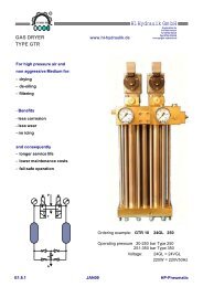
For high pressure air and<br />
non aggressive Medium for:<br />
- drying<br />
- de-oiling<br />
- filtering<br />
- Benefits<br />
- less corrosion<br />
- less wear<br />
- no icing<br />
SCHRUPP<br />
GAS DRYER<br />
TYPE GTR<br />
and consequently<br />
- longer service life<br />
- lower maintenance costs<br />
- fail-safe operation<br />
P<br />
T<br />
A<br />
R<br />
www.hl-hydraulik.de<br />
<strong>HL</strong> <strong>Hydraulik</strong> <strong>GmbH</strong><br />
Kupferhütte 5c<br />
D-57562 Herdorf<br />
Tel 02744-9324-0<br />
Fax 02744-9324-56<br />
schrupp@hl-hydraulik.de<br />
Ordering example: GTR 10 24GL 250<br />
Operating pressure 30-250 bar Type 250<br />
251-350 bar Type 350<br />
Voltage: 24GL = 24VGL<br />
220W = 220V50Hz<br />
E1.8.1 JAN09 <strong>HP</strong>-Pneumatic
Technical Data<br />
Operating Pressure<br />
Flow Rate<br />
Regeneration Air<br />
Volume of Reservoir<br />
Max. Temperature<br />
Relative Humidity<br />
Voltage<br />
Power Consumption<br />
Baseplate Material<br />
Mounting Plate Material<br />
Reservoirs Material<br />
A and P Ports<br />
Weight<br />
SCHRUPP<br />
GAS DRYER<br />
TYPE GTR<br />
Part code Bracket<br />
GTR K 507335<br />
30 - 350 bar<br />
1000 L/min<br />
5-10% of Compressor<br />
0,7 cdm<br />
40°C<br />
100%<br />
24GL, 220W<br />
35W<br />
Brass / stainless steel<br />
Brass / stainless steel<br />
Steel Chem. Nickel Plates<br />
G 3/8“<br />
44 Kg<br />
Part code program control unit<br />
GTR PS 24GL (or 220W)<br />
R<br />
www.hl-hydraulik.de<br />
<strong>HL</strong> <strong>Hydraulik</strong> <strong>GmbH</strong><br />
Destination<br />
Symbol<br />
Designation<br />
Conn.<br />
No.<br />
1K1 7<br />
Terminal<br />
Strip<br />
X1<br />
Y3 A1 6 K1<br />
Y2 A1 5 K2<br />
Y1 A1 4 K2<br />
PE 3<br />
Y2 PE 3 Y3<br />
Y1 PE 3<br />
Y2 A2 2<br />
Kupferhütte 5c<br />
D-57562 Herdorf<br />
Tel 02744-9324-0<br />
Fax 02744-9324-56<br />
schrupp@hl-hydraulik.de<br />
Y1 A2 2 Y3<br />
L02 2 K1<br />
L01 1 K1<br />
Destination<br />
symbol<br />
E1.8.2 JAN09 <strong>HP</strong>-Pneumatic<br />
Designation<br />
Conn.<br />
No.<br />
A1<br />
34<br />
32<br />
PE<br />
A2<br />
A2<br />
15
For compressed air and non aggressive gaseous media<br />
drying de-oiling filtering<br />
this means<br />
less corrosion less wear and no icing during operation<br />
and therefore<br />
greater service life lower maaintenance costs<br />
The gasdrier consists of two reservoirs filled with highly<br />
porous hydrostatic materials (adsorbents), into which<br />
damp com-pressed air and dried depressurized air are<br />
alternately admitted for the regeneration phase.<br />
The inlet and outlet of the adsorbent reservoirs are each<br />
fitted with a sintered metal disk to filter the water and oil<br />
particles out and also any particles from the adsorbate material.<br />
Because of the modular design it is possible to flange up to<br />
three units togethe. The Basic unit includes all necassary<br />
directional, throttle and check valve funktions.<br />
The second and third untits include the additional adsorbent<br />
reservoirs to increase the capacity of the system.<br />
Technical Data:<br />
Operating pressure 40 – 350bar<br />
Regeneration air consumtion appr. 5%<br />
Flow rate per unit 1300 l/min<br />
750<br />
SCHRUPP<br />
GAS DRYER<br />
TYPE GTF<br />
R<br />
150 150 150 260<br />
www.hl-hydraulik.de<br />
<strong>HL</strong> <strong>Hydraulik</strong> <strong>GmbH</strong><br />
Kupferhütte 5c<br />
D-57562 Herdorf<br />
Tel 02744-9324-0<br />
Fax 02744-9324-56<br />
schrupp@hl-hydraulik.de<br />
E1.8.3 JAN09 <strong>HP</strong>-Pneumatic<br />
P
SCHRUPP<br />
GAS DRYER<br />
TYPE GTR<br />
SCHRUPP<br />
DRIER<br />
STATIONS<br />
For<br />
− drying<br />
− de-oiling<br />
− filtering<br />
compressed air and non-<br />
aggressive gaseous media<br />
This means<br />
− less corrosion<br />
− less wear and<br />
− no icing<br />
during operation<br />
R<br />
www.hl-hydraulik.de<br />
and therefore<br />
− greater service life<br />
− lower maintenance costs and<br />
− fail safe operation<br />
<strong>HL</strong> <strong>Hydraulik</strong> <strong>GmbH</strong><br />
Kupferhütte 5c<br />
D-57562 Herdorf<br />
Tel 02744-9324-0<br />
Fax 02744-9324-56<br />
schrupp@hl-hydraulik.de<br />
E1.8.4 JAN09 <strong>HP</strong>-Pneumatic
SCHRUPP<br />
GAS DRYER<br />
TYPE GTR<br />
SCHRUPP GAS DRYER STATIONS<br />
Optional with Bypass<br />
For compressed Air and other<br />
non aggresive gaseous media:<br />
- drying<br />
- de-oiling<br />
- filtering<br />
R<br />
this means<br />
- less corrosion<br />
- less wear and<br />
- no icing<br />
- depressurised standby function<br />
and therefore<br />
- greater service life<br />
- lower maintenance costs and<br />
- fail save operation<br />
www.hl-hydraulik.de<br />
<strong>HL</strong> <strong>Hydraulik</strong> <strong>GmbH</strong><br />
Kupferhütte 5c<br />
D-57562 Herdorf<br />
Tel 02744-9324-0<br />
Fax 02744-9324-56<br />
schrupp@hl-hydraulik.de<br />
E1.8.6 JAN09 <strong>HP</strong>-Pneumatic
SCHRUPP<br />
GAS DRYER<br />
TYPE GTR<br />
Functional Description<br />
R<br />
The drier station consists of the gas drier, fine<br />
filter, pressure relief valve, pressure holding and<br />
check valves and the electrical control unit.<br />
These components are mounted on a frame, pipe<br />
connected and wired ready for operation. The<br />
gas drier consists of two reservoirs filled with<br />
highly porous hydrostatic materials (adsorbents),<br />
into which damp com-pressed air and dried<br />
depressurized air are alternately admitted for the<br />
regeneration phase.<br />
The damp air coming from the compressor<br />
passes through the fine filter (6) and the<br />
energized open 3/2-way valve DN 6 (1.1), which<br />
voltage is being passed, and reaches the<br />
reservoir (1.5).<br />
www.hl-hydraulik.de<br />
The adsorbent in reservoir (1.5) removes the moisture from the damp compressed air as it passes through<br />
this reservoir. The now dry air passes via the check valve (1.9), pressure holding valve (4) and check valve<br />
(5.1) to the storage vessel or to the consumer. A small portion of this dried compressed air is depressurized<br />
in the throttle valve (1.11) and flows through the check valve (1.8) to the reservoir (1.6). This dried air<br />
absorbs the water from the damp adsorbents and passes via the 3/2-way valve (1.2) into the atmosphere,<br />
thus regenerating the adsorbents.<br />
The inlet and outlet of the adsorbent reservoirs are each fitted with a sintered metal disk. These disks filter<br />
the water and oil particles out of the incoming damp air and any particles of adsorbate material from the<br />
outgoing air.<br />
Since drying and regeneration are performed in a counter-flow procedure, any residues are removed from<br />
the sintered metal disks at each reversal of the direction of flow.<br />
After the preset time interval (e.g. 10 minutes), the two 3/2-way valves (1.1 and 1.2) are automatically<br />
reversed via a timer switch.<br />
The procedure described above is now repeated but with the reservoirs “reversed”.<br />
The drying procedure is connected to the operation of the compressor. When the compressor is switched<br />
off, both 3/2-way valves (1.1 and 1.2) are closed (off position).<br />
The pressure relief valve (7) opens and the condensate in the fine filter (6) is discharged.<br />
When the compressor is restarted, the frying procedure is continued where it was interrupted.<br />
<strong>HL</strong> <strong>Hydraulik</strong> <strong>GmbH</strong><br />
Using this method, extremely low pressure dew points can be achieved (depending on the operating<br />
pressure, down to –50°C and lower measured at the drier outlet).<br />
Kupferhütte 5c<br />
D-57562 Herdorf<br />
Tel 02744-9324-0<br />
Fax 02744-9324-56<br />
schrupp@hl-hydraulik.de<br />
E1.8.7 JAN09 <strong>HP</strong>-Pneumatic
SCHRUPP<br />
GAS DRYER<br />
TYPE GTR<br />
The drier station consists of:<br />
1 1 Gas drier Type GT 1000/250<br />
Max. operating pressure 45 bar<br />
Flow rate 1000 l/min<br />
Regeneration air 5-10% of compressor<br />
rating<br />
Control voltage AC or DC<br />
2 1 Electrical control unit Type 168 332<br />
with time lag switching-off<br />
3 1 Silencer Type 162 987<br />
4 1 Pressure holding valve Type V 501 b<br />
Set to (max. 45 bar)<br />
5 2 Check valves Type Ap 9308<br />
DN 15, PN 45<br />
6 1 Fine filter Type 450 688<br />
Capacity 0.65 liter<br />
7 1 2/2-way valve Type 500 004<br />
DN 6, PN 250<br />
Voltage 220 V, 50 Hz<br />
8 1 Mounting frame Type 169 286<br />
Installation, connection, bolts, cables, etc.<br />
All above components assembled, piped connected,<br />
wired and tested<br />
Product No. 169 300<br />
The drier station consists of:<br />
R<br />
1 1 Gas drier Type GT 1000/250<br />
Max. operating pressure 250 bar<br />
Flow rate 1000 l/min<br />
Regeneration air 5-10% of compressor<br />
rating<br />
Control voltage AC or DC<br />
2 1 Electrical control unit Type 168 332<br />
with time lag switching-off<br />
3 1 Silencer Type 162 987<br />
4 1 Pressure holding valve<br />
Set to (max. 250 bar)<br />
5 2 Check valves Type 450 050<br />
DN 8, PN 250<br />
6 1 Fine filter Type 450 688<br />
Capacity 0.65 liter<br />
7 1 2/2-way valve Type 500 004<br />
DN 6, PN 250<br />
Voltage 220 V, 50 Hz<br />
8 1 Mounting frame Type 450 738<br />
Installation, connection, bolts, cables, etc.<br />
All above components assembled, piped connected,<br />
wired and tested<br />
Product No. 169 460<br />
www.hl-hydraulik.de<br />
<strong>HL</strong> <strong>Hydraulik</strong> <strong>GmbH</strong><br />
Kupferhütte 5c<br />
D-57562 Herdorf<br />
Tel 02744-9324-0<br />
Fax 02744-9324-56<br />
schrupp@hl-hydraulik.de<br />
E1.8.8 JAN09 <strong>HP</strong>-Pneumatic
SCHRUPP<br />
GAS DRYER<br />
TYPE GTR<br />
R<br />
www.hl-hydraulik.de<br />
Destination<br />
Symbol<br />
<strong>HL</strong> <strong>Hydraulik</strong> <strong>GmbH</strong><br />
Terminal<br />
Strip<br />
Kupferhütte 5c<br />
D-57562 Herdorf<br />
Tel 02744-9324-0<br />
Fax 02744-9324-56<br />
schrupp@hl-hydraulik.de<br />
Destination<br />
symbol<br />
E1.8.9 JAN09 <strong>HP</strong>-Pneumatic<br />
Designation<br />
Conn.<br />
No.<br />
1K1 7<br />
X1<br />
Y3 A1 6 K1<br />
Y2 A1 5 K2<br />
Y1 A1 4 K2<br />
PE 3<br />
Designation<br />
Y2 PE 3 Y3<br />
Y1 PE 3<br />
Y2 A2 2<br />
Y1 A2 2 Y3<br />
L02 2 K1<br />
L01 1 K1<br />
Conn.<br />
No.<br />
A1<br />
34<br />
32<br />
PE<br />
A2<br />
A2<br />
15