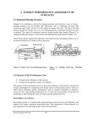
1. energy performance assessment of boilers - National Certification ...
1. energy performance assessment of boilers - National Certification ...
1. energy performance assessment of boilers - National Certification ...

Create successful ePaper yourself
Turn your PDF publications into a flip-book with our unique Google optimized e-Paper software.
<strong>1.</strong> ENERGY PERFORMANCE ASSESSMENT OF<br />
BOILERS<br />
<strong>1.</strong>1 Introduction<br />
Performance <strong>of</strong> the boiler, like efficiency and evaporation ratio reduces with time, due to<br />
poor combustion, heat transfer fouling and poor operation and maintenance. Deterioration<br />
<strong>of</strong> fuel quality and water quality also leads to poor <strong>performance</strong> <strong>of</strong> boiler. Efficiency<br />
testing helps us to find out how far the boiler efficiency drifts away from the best<br />
efficiency. Any observed abnormal deviations could therefore be investigated to pinpoint<br />
the problem area for necessary corrective action. Hence it is necessary to find out the<br />
current level <strong>of</strong> efficiency for <strong>performance</strong> evaluation, which is a pre requisite for <strong>energy</strong><br />
conservation action in industry.<br />
<strong>1.</strong>2 Purpose <strong>of</strong> the Performance Test<br />
• To find out the efficiency <strong>of</strong> the boiler<br />
• To find out the Evaporation ratio<br />
The purpose <strong>of</strong> the <strong>performance</strong> test is to determine actual <strong>performance</strong> and efficiency <strong>of</strong><br />
the boiler and compare it with design values or norms. It is an indicator for tracking dayto-day<br />
and season-to-season variations in boiler efficiency and <strong>energy</strong> efficiency<br />
improvements<br />
<strong>1.</strong>3 Performance Terms and Definitions<br />
Heat output<br />
<strong>1.</strong> Boiler Efficiency, η = x100<br />
Heat input<br />
Heat in steamoutput ( kCals)<br />
= x100<br />
Heat in fuel input ( kCals)<br />
2. Evaporation Ratio =<br />
Quantity <strong>of</strong><br />
Quantity <strong>of</strong><br />
steam generation<br />
fuel consumption<br />
<strong>1.</strong>4 Scope<br />
The procedure describes routine test for both oil fired and solid fuel fired <strong>boilers</strong> using<br />
coal, agro residues etc. Only those observations and measurements need to be made<br />
which can be readily applied and is necessary to attain the purpose <strong>of</strong> the test.<br />
Bureau <strong>of</strong> Energy Efficiency 1
<strong>1.</strong> Energy Performance Assessment <strong>of</strong> Boilers<br />
<strong>1.</strong>5 Reference Standards<br />
British standards, BS845: 1987<br />
The British Standard BS845: 1987 describes the methods and conditions under which a<br />
boiler should be tested to determine its efficiency. For the testing to be done, the boiler<br />
should be operated under steady load conditions (generally full load) for a period <strong>of</strong> one<br />
hour after which readings would be taken during the next hour <strong>of</strong> steady operation to<br />
enable the efficiency to be calculated.<br />
The efficiency <strong>of</strong> a boiler is quoted as the % <strong>of</strong> useful heat available, expressed as a<br />
percentage <strong>of</strong> the total <strong>energy</strong> potentially available by burning the fuel. This is expressed<br />
on the basis <strong>of</strong> gross calorific value (GCV) .<br />
This deals with the complete heat balance and it has two parts:<br />
Part One deals with standard <strong>boilers</strong>, where the indirect method is specified<br />
Part Two deals with complex plant where there are many channels <strong>of</strong> heat flow.<br />
In this case, both the direct and indirect methods are applicable, in whole or in<br />
part.<br />
ASME Standard: PTC-4-1 Power Test Code for Steam Generating Units<br />
This consists <strong>of</strong><br />
Part One: Direct method (also called as Input -output method)<br />
Part Two: Indirect method (also called as Heat loss method)<br />
IS 8753: Indian Standard for Boiler Efficiency Testing<br />
Most standards for computation <strong>of</strong> boiler efficiency, including IS 8753 and BS845 are<br />
designed for spot measurement <strong>of</strong> boiler efficiency. Invariably, all these standards do<br />
not include blow down as a loss in the efficiency determination process.<br />
Basically Boiler efficiency can be tested by the following methods:<br />
1) The Direct Method: Where the <strong>energy</strong> gain <strong>of</strong> the working fluid (water and<br />
steam) is compared with the <strong>energy</strong> content <strong>of</strong> the boiler fuel.<br />
2) The Indirect Method: Where the efficiency is the difference between the losses<br />
and the <strong>energy</strong> input.<br />
<strong>1.</strong>6 The Direct Method Testing<br />
<strong>1.</strong>6.1 Description<br />
This is also known as ‘input-output method’ due to the fact that it needs only the useful<br />
output (steam) and the heat input (i.e. fuel) for evaluating the efficiency. This efficiency<br />
can be evaluated using the formula:<br />
Boiler Efficiency =<br />
Heat Output<br />
x100<br />
Heat Input<br />
Bureau <strong>of</strong> Energy Efficiency 2
Water<br />
Steam Output<br />
<strong>1.</strong> Energy Performance Assessment <strong>of</strong> Boilers<br />
Flue<br />
Gas<br />
Fuel Input 100%<br />
+ Air<br />
Boiler<br />
Efficiency = Heat addition to Steam x 100<br />
Gross Heat in Fuel<br />
Boiler Efficiency<br />
=<br />
Steam flow rate x (steam enthalpy − feed water enthalpy)<br />
Fuel firing rate x Gross calorific value<br />
x 100<br />
<strong>1.</strong>6.2 Measurements Required for Direct Method Testing<br />
Heat input<br />
Both heat input and heat output must be measured. The measurement <strong>of</strong> heat input<br />
requires knowledge <strong>of</strong> the calorific value <strong>of</strong> the fuel and its flow rate in terms <strong>of</strong> mass or<br />
volume, according to the nature <strong>of</strong> the fuel.<br />
For gaseous fuel: A gas meter <strong>of</strong> the approved type can be used and the measured<br />
volume should be corrected for temperature and pressure. A sample <strong>of</strong> gas can be<br />
collected for calorific value determination, but it is usually acceptable to use the<br />
calorific value declared by the gas suppliers.<br />
For liquid fuel: Heavy fuel oil is very viscous, and this property varies sharply<br />
with temperature. The meter, which is usually installed on the combustion<br />
appliance, should be regarded as a rough indicator only and, for test purposes, a<br />
meter calibrated for the particular oil is to be used and over a realistic range <strong>of</strong><br />
temperature should be installed. Even better is the use <strong>of</strong> an accurately calibrated<br />
day tank.<br />
For solid fuel: The accurate measurement <strong>of</strong> the flow <strong>of</strong> coal or other solid fuel is<br />
very difficult. The measurement must be based on mass, which means that bulky<br />
apparatus must be set up on the boiler-house floor. Samples must be taken and<br />
bagged throughout the test, the bags sealed and sent to a laboratory for analysis<br />
and calorific value determination. In some more recent boiler houses, the problem<br />
has been alleviated by mounting the hoppers over the <strong>boilers</strong> on calibrated load<br />
cells, but these are yet uncommon.<br />
Heat output<br />
There are several methods, which can be used for measuring heat output. With steam<br />
<strong>boilers</strong>, an installed steam meter can be used to measure flow rate, but this must be<br />
Bureau <strong>of</strong> Energy Efficiency 3
<strong>1.</strong> Energy Performance Assessment <strong>of</strong> Boilers<br />
corrected for temperature and pressure. In earlier years, this approach was not favoured<br />
due to the change in accuracy <strong>of</strong> orifice or venturi meters with flow rate. It is now more<br />
viable with modern flow meters <strong>of</strong> the variable-orifice or vortex-shedding types.<br />
The alternative with small <strong>boilers</strong> is to measure feed water, and this can be done by<br />
previously calibrating the feed tank and noting down the levels <strong>of</strong> water during the<br />
beginning and end <strong>of</strong> the trial. Care should be taken not to pump water during this period.<br />
Heat addition for conversion <strong>of</strong> feed water at inlet temperature to steam, is considered for<br />
heat output.<br />
In case <strong>of</strong> <strong>boilers</strong> with intermittent blowdown, blowdown should be avoided during the<br />
trial period. In case <strong>of</strong> <strong>boilers</strong> with continuous blowdown, the heat loss due to blowdown<br />
should be calculated and added to the heat in steam.<br />
<strong>1.</strong>6.3 Boiler Efficiency by Direct Method: Calculation and Example<br />
Test Data and Calculation<br />
Water consumption and coal consumption were measured in a coal-fired boiler at hourly<br />
intervals. Weighed quantities <strong>of</strong> coal were fed to the boiler during the trial period.<br />
Simultaneously water level difference was noted to calculate steam generation during the<br />
trial period. Blow down was avoided during the test. The measured data is given below.<br />
Type <strong>of</strong> boiler: Coal fired Boiler<br />
Heat output data<br />
Quantity <strong>of</strong> steam generated (output)<br />
Steam pressure / temperature<br />
Enthalpy <strong>of</strong> steam(dry & Saturated)<br />
at 10 kg/cm 2 (g) pressure<br />
Feed water temperature<br />
Enthalpy <strong>of</strong> feed water<br />
: 8 TPH<br />
: 10 kg/cm 2 (g)/ 180 0 C<br />
: 665 kCal/kg<br />
: 85 0 C<br />
: 85 kCal/kg<br />
Heat input data<br />
Quantity <strong>of</strong> coal consumed (Input)<br />
GCV <strong>of</strong> coal<br />
: <strong>1.</strong>6 TPH<br />
: 4000 kCal/kg<br />
Calculation<br />
Q x(<br />
H − h)<br />
Boiler efficiency( η ) =<br />
x100<br />
q xGCV<br />
Where Q = Quantity <strong>of</strong> steam generated per hour (kg/hr)<br />
q = Quantity <strong>of</strong> fuel used per hour (kg/hr)<br />
GCV = Gross calorific value <strong>of</strong> the fuel (kCal/kg)<br />
H = Enthalpy <strong>of</strong> steam (kCal/kg)<br />
h = Enthalpy <strong>of</strong> feed water (kCal/kg)<br />
Bureau <strong>of</strong> Energy Efficiency 4
<strong>1.</strong> Energy Performance Assessment <strong>of</strong> Boilers<br />
8TPH x1000kg<br />
/ T x(665<br />
− 85)<br />
Boiler efficiency( η ) =<br />
x 100<br />
<strong>1.</strong>6TPH x1000kg<br />
/ T x 4000kCal<br />
/ kg<br />
= 72.5%<br />
Evaporation Ratio = 8 Tonne <strong>of</strong> steam / <strong>1.</strong>6 Tonne <strong>of</strong> coal<br />
= 5<br />
<strong>1.</strong>6.4 Merits and Demerits <strong>of</strong> Direct Method<br />
Merits<br />
• Plant people can evaluate quickly the efficiency <strong>of</strong> <strong>boilers</strong><br />
• Requires few parameters for computation<br />
• Needs few instruments for monitoring<br />
Demerits<br />
• Does not give clues to the operator as to why efficiency <strong>of</strong> system is lower<br />
• Does not calculate various losses accountable for various efficiency levels<br />
• Evaporation ratio and efficiency may mislead, if the steam is highly wet due to<br />
water carryover<br />
<strong>1.</strong>7 The Indirect Method Testing<br />
<strong>1.</strong>7.1 Description<br />
The efficiency can be measured easily by measuring all the losses occurring in the <strong>boilers</strong><br />
using the principles to be described. The disadvantages <strong>of</strong> the direct method can be<br />
overcome by this method, which calculates the various heat losses associated with boiler.<br />
The efficiency can be arrived at, by subtracting the heat loss fractions from 100.An<br />
important advantage <strong>of</strong> this method is that the errors in measurement do not make<br />
significant change in efficiency.<br />
Thus if boiler efficiency is 90% , an error <strong>of</strong> 1% in direct method will result in significant<br />
change in efficiency. i.e.90 + 0.9 = 89.1 to 90.9. In indirect method, 1% error in<br />
measurement <strong>of</strong> losses will result in<br />
Efficiency = 100 – (10 + 0.1) = 90 + 0.1 = 89.9 to 90.1<br />
Bureau <strong>of</strong> Energy Efficiency 5
<strong>1.</strong> Energy Performance Assessment <strong>of</strong> Boilers<br />
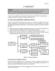
The various heat losses occurring in the boiler are:<br />
Steam Output<br />
6. Surface loss<br />
<strong>1.</strong> Dry Flue gas loss<br />
2. H2 loss<br />
3. Moisture in fuel<br />
4. Moisture in air<br />
5. CO loss<br />
Fuel Input, 100%<br />
Boiler<br />
Flue gas sample<br />
7. Fly ash loss<br />
Air<br />
Blow down<br />
8. Bottom ash loss<br />
Water<br />
Efficiency = 100 – (1+2+3+4+5+6+7+8) (by Indirect Method)<br />
The following losses are applicable to liquid, gas and solid fired boiler<br />
L1- Loss due to dry flue gas (sensible heat)<br />
L2- Loss due to hydrogen in fuel (H 2 )<br />
L3- Loss due to moisture in fuel (H 2 O)<br />
L4- Loss due to moisture in air (H 2 O)<br />
L5- Loss due to carbon monoxide (CO)<br />
L6- Loss due to surface radiation, convection and other unaccounted*.<br />
*Losses which are insignificant and are difficult to measure.<br />
The following losses are applicable to solid fuel fired boiler in addition to above<br />
L7- Unburnt losses in fly ash (Carbon)<br />
L8- Unburnt losses in bottom ash (Carbon)<br />
Boiler Efficiency by indirect method = 100 – (L1+L2+L3+L4+L5+L6+L7+L8)<br />
<strong>1.</strong>7.2 Measurements Required for Performance Assessment Testing<br />
The following parameters need to be measured, as applicable for the computation <strong>of</strong><br />
boiler efficiency and <strong>performance</strong>.<br />
a) Flue gas analysis<br />
<strong>1.</strong> Percentage <strong>of</strong> CO 2 or O 2 in flue gas<br />
2. Percentage <strong>of</strong> CO in flue gas<br />
3. Temperature <strong>of</strong> flue gas<br />
Bureau <strong>of</strong> Energy Efficiency 6
<strong>1.</strong> Energy Performance Assessment <strong>of</strong> Boilers<br />
b) Flow meter measurements for<br />
<strong>1.</strong> Fuel<br />
2. Steam<br />
3. Feed water<br />
4. Condensate water<br />
5. Combustion air<br />
c) Temperature measurements for<br />
<strong>1.</strong> Flue gas<br />
2. Steam<br />
3. Makeup water<br />
4. Condensate return<br />
5. Combustion air<br />
6. Fuel<br />
7. Boiler feed water<br />
d) Pressure measurements for<br />
<strong>1.</strong> Steam<br />
2. Fuel<br />
3. Combustion air, both primary and secondary<br />
4. Draft<br />
e) Water condition<br />
<strong>1.</strong> Total dissolved solids (TDS)<br />
2. pH<br />
3. Blow down rate and quantity<br />
The various parameters that were discussed above can be measured with the instruments<br />
that are given in Table <strong>1.</strong><strong>1.</strong><br />
Table <strong>1.</strong>1 Typical Instruments used for Boiler Performance Assessment.<br />
Instrument Type Measurements<br />
Flue gas analyzer Portable or fixed % CO 2 , O 2 and CO<br />
Temperature indicator<br />
Draft gauge<br />
Thermocouple, liquid in<br />
glass<br />
Manometer, differential<br />
pressure<br />
Fuel temperature, flue gas<br />
temperature, combustion air<br />
temperature, boiler surface<br />
temperature, steam temperature<br />
Amount <strong>of</strong> draft used or available<br />
TDS meter Conductivity Boiler water TDS, feed water TDS,<br />
Bureau <strong>of</strong> Energy Efficiency 7
<strong>1.</strong> Energy Performance Assessment <strong>of</strong> Boilers<br />
make-up water TDS.<br />
Flow meter As applicable Steam flow, water flow, fuel flow,<br />
air flow<br />
<strong>1.</strong>7.3 Test Conditions and Precautions for Indirect Method Testing<br />
A) The efficiency test does not account for:<br />
• Standby losses. Efficiency test is to be carried out, when the boiler is operating<br />
under a steady load. Therefore, the combustion efficiency test does not reveal<br />
standby losses, which occur between firing intervals<br />
• Blow down loss. The amount <strong>of</strong> <strong>energy</strong> wasted by blow down varies over a wide<br />
range.<br />
• Soot blower steam. The amount <strong>of</strong> steam used by soot blowers is variable that<br />
depends on the type <strong>of</strong> fuel.<br />
• Auxiliary equipment <strong>energy</strong> consumption. The combustion efficiency test does<br />
not account for the <strong>energy</strong> usage by auxiliary equipments, such as burners, fans,<br />
and pumps.<br />
B) Preparations and pre conditions for testing<br />
• Burn the specified fuel(s) at the required rate.<br />
• Do the tests while the boiler is under steady load. Avoid testing during warming<br />
up <strong>of</strong> <strong>boilers</strong> from a cold condition<br />
• Obtain the charts /tables for the additional data.<br />
• Determination <strong>of</strong> general method <strong>of</strong> operation<br />
• Sampling and analysis <strong>of</strong> fuel and ash.<br />
• Ensure the accuracy <strong>of</strong> fuel and ash analysis in the laboratory.<br />
• Check the type <strong>of</strong> blow down and method <strong>of</strong> measurement<br />
• Ensure proper operation <strong>of</strong> all instruments.<br />
• Check for any air infiltration in the combustion zone.<br />
C) Flue gas sampling location<br />
It is suggested that the exit duct <strong>of</strong> the boiler be probed and traversed to find the location<br />
<strong>of</strong> the zone <strong>of</strong> maximum temperature. This is likely to coincide with the zone <strong>of</strong><br />
maximum gas flow and is therefore a good sampling point for both temperature and gas<br />
analysis.<br />
D) Options <strong>of</strong> flue gas analysis<br />
Check the Oxygen Test with the Carbon Dioxide Test<br />
If continuous-reading oxygen test equipment is installed in boiler plant, use oxygen<br />
reading. Occasionally use portable test equipment that checks for both oxygen and carbon<br />
dioxide. If the carbon dioxide test does not give the same results as the oxygen test,<br />
something is wrong. One (or both) <strong>of</strong> the tests could be erroneous, perhaps because <strong>of</strong><br />
stale chemicals or drifting instrument calibration. Another possibility is that outside air is<br />
Bureau <strong>of</strong> Energy Efficiency 8
<strong>1.</strong> Energy Performance Assessment <strong>of</strong> Boilers<br />
being picked up along with the flue gas. This occurs if the combustion gas area operates<br />
under negative pressure and there are leaks in the boiler casing.<br />
Carbon Monoxide Test<br />
The carbon monoxide content <strong>of</strong> flue gas is a good indicator <strong>of</strong> incomplete combustion<br />
with all types <strong>of</strong> fuels, as long as they contain carbon. Carbon monoxide in the flue gas is<br />
minimal with ordinary amounts <strong>of</strong> excess air, but it rises abruptly as soon as fuel<br />
combustion starts to be incomplete.<br />
E) Planning for the testing<br />
• The testing is to be conducted for a duration <strong>of</strong> 4 to 8 hours in a normal production<br />
day.<br />
• Advanced planning is essential for the resource arrangement <strong>of</strong> manpower, fuel,<br />
water and instrument check etc and the same to be communicated to the boiler<br />
Supervisor and Production Department.<br />
• Sufficient quantity <strong>of</strong> fuel stock and water storage required for the test duration<br />
should be arranged so that a test is not disrupted due to non-availability <strong>of</strong> fuel and<br />
water.<br />
• Necessary sampling point and instruments are to be made available with working<br />
condition.<br />
• Lab Analysis should be carried out for fuel, flue gas and water in coordination<br />
with lab personnel.<br />
• The steam table, psychometric chart, calculator are to be arranged for computation<br />
<strong>of</strong> boiler efficiency.<br />
Bureau <strong>of</strong> Energy Efficiency 9
<strong>1.</strong> Energy Performance Assessment <strong>of</strong> Boilers<br />
<strong>1.</strong>7.4 Boiler Efficiency by Indirect Method: Calculation Procedure and Formula<br />
In order to calculate the boiler efficiency by indirect method, all the losses that occur in<br />
the boiler must be established. These losses are conveniently related to the amount <strong>of</strong><br />
fuel burnt. In this way it is easy to compare the <strong>performance</strong> <strong>of</strong> various <strong>boilers</strong> with<br />
different ratings.<br />
Conversion formula for proximate analysis to ultimate analysis<br />
%C = 0.97C+ 0.7(VM+0.1A) - M(0.6-0.01M)<br />
%H 2 = 0.036C + 0.086 (VM -0.1xA) - 0.0035M 2 (1-0.02M)<br />
%N 2 = 2.10 -0.020 VM<br />
where C<br />
A<br />
VM<br />
M<br />
= % <strong>of</strong> fixed carbon<br />
= % <strong>of</strong> ash<br />
= % <strong>of</strong> volatile matter<br />
= % <strong>of</strong> moisture<br />
However it is suggested to get a ultimate analysis <strong>of</strong> the fuel fired periodically from a<br />
reputed laboratory.<br />
Theoretical (stoichiometric) air fuel ratio and excess air supplied are to be determined<br />
first for computing the boiler losses. The formula is given below for the same.<br />
a) Theoretical air<br />
required for<br />
combustion<br />
b) % Excess Air<br />
supplied (EA)<br />
= [( 1<strong>1.</strong>6 x C)<br />
+ {34.8 x(<br />
H<br />
2<br />
− O2<br />
/8)} + (4.35 x S)]/<br />
100 kg/kg <strong>of</strong><br />
fuel. [from fuel analysis]<br />
=<br />
Where C, H 2 , O 2 and S are the percentage <strong>of</strong> carbon, hydrogen,<br />
oxygen and sulphur present in the fuel.<br />
O2 %<br />
x100<br />
[from flue gas analysis]<br />
21−<br />
O2%<br />
Normally O 2 measurement is recommended. If O 2<br />
measurement is not available, use CO 2 measurement<br />
7900 x[(<br />
CO2<br />
%)<br />
t<br />
− ( CO2<br />
%)<br />
a]<br />
[from flue gas analysis]<br />
( CO ) % x [100 − ( CO %) ]<br />
Where, (CO 2 %) t = Theoretical CO 2<br />
(CO 2 %) a<br />
= Actual CO 2 % measured in flue gas<br />
Moles<strong>of</strong> C<br />
( CO 2 ) t = Moles<strong>of</strong> N + Moles<strong>of</strong> C<br />
2<br />
a<br />
Moles <strong>of</strong> N 2 =<br />
Wt <strong>of</strong> N2<br />
in theoritical air Wt <strong>of</strong> N2<br />
in fuel<br />
+<br />
Mol. wt <strong>of</strong> N2<br />
Mol.<br />
Wt <strong>of</strong> N2<br />
Moles <strong>of</strong> C = Wt <strong>of</strong> C in fuel<br />
Molecular Wt <strong>of</strong> C<br />
c) Actual mass <strong>of</strong> = {1 + EA/100} x theoretical air<br />
air supplied/ kg <strong>of</strong><br />
fuel (AAS)<br />
2<br />
2<br />
t<br />
Bureau <strong>of</strong> Energy Efficiency 10
<strong>1.</strong> Energy Performance Assessment <strong>of</strong> Boilers<br />
The various losses associated with the operation <strong>of</strong> a boiler are discussed below with<br />
required formula.<br />
<strong>1.</strong> Heat loss due to dry flue gas<br />
This is the greatest boiler loss and can be calculated with the following formula:<br />
Where,<br />
L 1 =<br />
L 1<br />
m<br />
C p<br />
T f<br />
T a<br />
m xC<br />
p<br />
x(<br />
T<br />
GCV <strong>of</strong><br />
f<br />
− T )<br />
fuel<br />
a<br />
x 100<br />
= % Heat loss due to dry flue gas<br />
= Mass <strong>of</strong> dry flue gas in kg/kg <strong>of</strong> fuel<br />
= Combustion products from fuel: CO 2 + SO 2 + Nitrogen in fuel +<br />
Nitrogen in the actual mass <strong>of</strong> air supplied + O 2 in flue gas.<br />
(H 2 O/Water vapour in the flue gas should not be considered)<br />
= Specific heat <strong>of</strong> flue gas in kCal/kg<br />
= Flue gas temperature in o C<br />
= Ambient temperature in o C<br />
Note-1:<br />
For Quick and simple calculation <strong>of</strong> boiler efficiency use the following.<br />
A: Simple method can be used for determining the dry flue gas loss as given below.<br />
m xC<br />
p<br />
x(<br />
Tf<br />
− Ta<br />
)<br />
a) Percentage heat loss due to dry flue gas = x 100<br />
GCV <strong>of</strong> fuel<br />
Total mass <strong>of</strong> flue gas (m)/kg <strong>of</strong> fuel = mass <strong>of</strong> actual air supplied/kg <strong>of</strong> fuel + 1 kg <strong>of</strong><br />
fuel<br />
Note-2: Water vapour is produced from Hydrogen in fuel, moisture present in fuel and air<br />
during the combustion. The losses due to these components have not been included in the<br />
dry flue gas loss since they are separately calculated as a wet flue gas loss.<br />
2. Heat loss due to evaporation <strong>of</strong> water formed due to H 2 in fuel (%)<br />
The combustion <strong>of</strong> hydrogen causes a heat loss because the product <strong>of</strong> combustion is<br />
water. This water is converted to steam and this carries away heat in the form <strong>of</strong> its<br />
latent heat.<br />
Where<br />
9 x H2<br />
x {584 + Cp<br />
(Tf<br />
- Ta<br />
)}<br />
L 2 = x 100<br />
GCV <strong>of</strong> fuel<br />
H 2<br />
C p<br />
T f<br />
= kg <strong>of</strong> hydrogen present in fuel on 1 kg basis<br />
= Specific heat <strong>of</strong> superheated steam in kCal/kg o C<br />
= Flue gas temperature in o C<br />
Bureau <strong>of</strong> Energy Efficiency 11
<strong>1.</strong> Energy Performance Assessment <strong>of</strong> Boilers<br />
T a = Ambient temperature in o C<br />
584 = Latent heat corresponding to partial pressure <strong>of</strong> water vapour<br />
3. Heat loss due to moisture present in fuel<br />
Moisture entering the boiler with the fuel leaves as a superheated vapour. This moisture<br />
loss is made up <strong>of</strong> the sensible heat to bring the moisture to boiling point, the latent heat<br />
<strong>of</strong> evaporation <strong>of</strong> the moisture, and the superheat required to bring this steam to the<br />
temperature <strong>of</strong> the exhaust gas. This loss can be calculated with the following formula<br />
where<br />
L 3 =<br />
M x {584 + Cp<br />
(Tf<br />
- Ta<br />
)}<br />
GCV <strong>of</strong> fuel<br />
x 100<br />
M = kg <strong>of</strong> moisture in fuel in 1 kg basis<br />
C p = Specific heat <strong>of</strong> superheated steam in kCal/kg o C<br />
T f = Flue gas temperature in o C<br />
T a = Ambient temperature in o C<br />
584 = Latent heat corresponding to partial pressure <strong>of</strong> water vapour<br />
4. Heat loss due to moisture present in air<br />
Vapour in the form <strong>of</strong> humidity in the incoming air, is superheated as it passes through<br />
the boiler. Since this heat passes up the stack, it must be included as a boiler loss.<br />
To relate this loss to the mass <strong>of</strong> coal burned, the moisture content <strong>of</strong> the combustion air<br />
and the amount <strong>of</strong> air supplied per unit mass <strong>of</strong> coal burned must be known.<br />
The mass <strong>of</strong> vapour that air contains can be obtained from psychrometric charts and<br />
typical values are included below:<br />
Dry-Bulb Wet Bulb Relative Humidity Kilogram water<br />
Temp o C Temp o C (%) per Kilogram dry<br />
air (Humidity<br />
Factor)<br />
20 20 100 0.016<br />
20 14 50 0.008<br />
30 22 50 0.014<br />
40 30 50 0.024<br />
where<br />
AAS x humidity factor x Cp<br />
x (Tf<br />
- Ta<br />
)<br />
L 4 = x 100<br />
GCV <strong>of</strong> fuel<br />
AAS = Actual mass <strong>of</strong> air supplied per kg <strong>of</strong> fuel<br />
Humidity factor = kg <strong>of</strong> water/kg <strong>of</strong> dry air<br />
C p = Specific heat <strong>of</strong> superheated steam in kCal/kg o C<br />
T f = Flue gas temperature in o C<br />
T a = Ambient temperature in o C (dry bulb)<br />
Bureau <strong>of</strong> Energy Efficiency 12
<strong>1.</strong> Energy Performance Assessment <strong>of</strong> Boilers<br />
5. Heat loss due to incomplete combustion:<br />
Products formed by incomplete combustion could be mixed with oxygen and burned<br />
again with a further release <strong>of</strong> <strong>energy</strong>. Such products include CO, H 2 , and various<br />
hydrocarbons and are generally found in the flue gas <strong>of</strong> the <strong>boilers</strong>. Carbon monoxide is<br />
the only gas whose concentration can be determined conveniently in a boiler plant test.<br />
L 5 =<br />
% CO x C 5744<br />
x<br />
x 100<br />
% CO + % CO2<br />
GCV <strong>of</strong> fuel<br />
L 5<br />
= % Heat loss due to partial conversion <strong>of</strong> C to CO<br />
CO = Volume <strong>of</strong> CO in flue gas leaving economizer (%)<br />
CO 2 = Actual Volume <strong>of</strong> CO 2 in flue gas (%)<br />
C<br />
= Carbon content kg / kg <strong>of</strong> fuel<br />
or<br />
When CO is obtained in ppm during the flue gas analysis<br />
CO formation (M co ) = CO (in ppm) x 10 -6 x M f x 28<br />
M f<br />
= Fuel consumption in kg/hr<br />
L 5 = M co x 5744*<br />
* Heat loss due to partial combustion <strong>of</strong> carbon.<br />
6. Heat loss due to radiation and convection:<br />
The other heat losses from a boiler consist <strong>of</strong> the loss <strong>of</strong> heat by radiation and convection<br />
from the boiler casting into the surrounding boiler house.<br />
Normally surface loss and other unaccounted losses is assumed based on the type<br />
and size <strong>of</strong> the boiler as given below<br />
For industrial fire tube / packaged boiler = <strong>1.</strong>5 to 2.5%<br />
For industrial watertube boiler = 2 to 3%<br />
For power station boiler = 0.4 to 1%<br />
However it can be calculated if the surface area <strong>of</strong> boiler and its surface temperature are<br />
known as given below :<br />
where<br />
L 6<br />
= 0.548 x [ (T s / 55.55) 4 – (T a / 55.55) 4 ] + <strong>1.</strong>957 x (T s – T a ) <strong>1.</strong>25 x sq.rt <strong>of</strong><br />
[(196.85 V m + 68.9) / 68.9]<br />
L 6 = Radiation loss in W/m 2<br />
V m<br />
T s<br />
T a<br />
= Wind velocity in m/s<br />
= Surface temperature (K)<br />
= Ambient temperature (K)<br />
Bureau <strong>of</strong> Energy Efficiency 13
<strong>1.</strong> Energy Performance Assessment <strong>of</strong> Boilers<br />
Heat loss due to unburned carbon in fly ash and bottom ash:<br />
Small amounts <strong>of</strong> carbon will be left in the ash and this constitutes a loss <strong>of</strong> potential heat<br />
in the fuel. To assess these heat losses, samples <strong>of</strong> ash must be analyzed for carbon<br />
content. The quantity <strong>of</strong> ash produced per unit <strong>of</strong> fuel must also be known.<br />
7. Heat loss due to unburnt in fly ash (%).<br />
Total ash collected / kg <strong>of</strong> fuel burnt x<br />
L =<br />
GCV <strong>of</strong> fuel<br />
G.C.V <strong>of</strong> fly ash<br />
7<br />
x<br />
100<br />
8. Heat loss due to unburnt in bottom ash (%)<br />
Total ash collected / kg <strong>of</strong> fuel burnt x<br />
L =<br />
GCV <strong>of</strong> fuel<br />
G.C.V <strong>of</strong> bottom ash<br />
8<br />
x<br />
Heat Balance:<br />
Having established the magnitude <strong>of</strong> all the losses mentioned above, a simple heat<br />
balance would give the efficiency <strong>of</strong> the boiler. The efficiency is the difference between<br />
the <strong>energy</strong> input to the boiler and the heat losses calculated.<br />
Boiler Heat Balance:<br />
100<br />
Input/Output Parameter kCal / kg <strong>of</strong> fuel %<br />
Heat Input in fuel = 100<br />
Various Heat losses in boiler<br />
<strong>1.</strong> Dry flue gas loss =<br />
2. Loss due to hydrogen in fuel<br />
3. Loss due to moisture in fuel =<br />
4. Loss due to moisture in air =<br />
5. Partial combustion <strong>of</strong> C to CO =<br />
6. Surface heat losses =<br />
7. Loss due to Unburnt in fly ash =<br />
8. Loss due to Unburnt in bottom =<br />
ash<br />
Total Losses =<br />
Boiler efficiency = 100 – (1+2+3+4+5+6+7+8)<br />
Bureau <strong>of</strong> Energy Efficiency 14
<strong>1.</strong> Energy Performance Assessment <strong>of</strong> Boilers<br />
<strong>1.</strong>8 Example: Boiler Efficiency Calculation<br />
<strong>1.</strong>8.1 For Coal fired Boiler<br />
The following are the data collected for a boiler using coal as the fuel. Find out the boiler<br />
efficiency by indirect method.<br />
Fuel firing rate = 5599.17 kg/hr<br />
Steam generation rate = 21937.5 kg/hr<br />
Steam pressure = 43 kg/cm 2 (g)<br />
Steam temperature = 377 o C<br />
Feed water temperature = 96 o C<br />
%CO 2 in Flue gas = 14<br />
%CO in flue gas = 0.55<br />
Average flue gas temperature = 190 o C<br />
Ambient temperature = 31 o C<br />
Humidity in ambient air = 0.0204 kg / kg dry air<br />
Surface temperature <strong>of</strong> boiler = 70 o C<br />
Wind velocity around the boiler = 3.5 m/s<br />
Total surface area <strong>of</strong> boiler = 90 m 2<br />
GCV <strong>of</strong> Bottom ash = 800 kCal/kg<br />
GCV <strong>of</strong> fly ash = 452.5 kCal/kg<br />
Ratio <strong>of</strong> bottom ash to fly ash = 90:10<br />
Fuel Analysis (in %)<br />
Ash content in fuel = 8.63<br />
Moisture in coal = 3<strong>1.</strong>6<br />
Carbon content = 4<strong>1.</strong>65<br />
Hydrogen content = 2.0413<br />
Nitrogen content = <strong>1.</strong>6<br />
Oxygen content = 14.48<br />
GCV <strong>of</strong> Coal = 3501 kCal/kg<br />
Bureau <strong>of</strong> Energy Efficiency 15
<strong>1.</strong> Energy Performance Assessment <strong>of</strong> Boilers<br />
Boiler efficiency by indirect method<br />
Step – 1 Find theoretical air<br />
requirement<br />
Theoretical air required for<br />
complete combustion<br />
= [( 1<strong>1.</strong>6 x C)<br />
+ {34.8 x(<br />
H<br />
2<br />
− O2<br />
/8)} + (4.35 x S)]/<br />
100<br />
kg/kg <strong>of</strong> coal<br />
= [(1<strong>1.</strong>6 x 4<strong>1.</strong>65) + {34.8 x (2.0413 – 14.48/8)} +<br />
(4.35 x 0)] / 100<br />
= 4.91 kg / kg <strong>of</strong> coal<br />
Step – 2 Find theoretical CO 2 %<br />
Moles<strong>of</strong> C<br />
% CO 2 at theoretical condition = Moles<strong>of</strong> N2<br />
+ Moles<strong>of</strong> C<br />
( CO 2 ) t<br />
Where,<br />
Wt <strong>of</strong> N2<br />
in theoritical air Wt <strong>of</strong> N2<br />
in fuel<br />
Moles <strong>of</strong> N 2 =<br />
+<br />
Mol. wt <strong>of</strong> N Mol.<br />
Wt <strong>of</strong> N<br />
2<br />
2<br />
Moles <strong>of</strong> N 2 =<br />
4.91x77 /100<br />
28<br />
+<br />
0.016<br />
28<br />
= 0.1356<br />
Where moles <strong>of</strong> C = 0.4165/12 = 0.0347<br />
0.0347<br />
( CO 2 ) t = 0.1332 + 0. 0347<br />
Step – 3 To find Excess air<br />
supplied<br />
( CO 2 ) t = 20.37%<br />
Actual CO 2 measured in flue gas = 14.0%<br />
% Excess air supplied (EA) =<br />
7900 x[(<br />
CO2<br />
%)<br />
t<br />
− ( CO2<br />
%)<br />
a]<br />
( CO2<br />
)<br />
a%<br />
x [100 − ( CO2<br />
%)<br />
t<br />
]<br />
7900 x[20.37<br />
−14]<br />
= 14 x [100 − 20.37]<br />
= 45.17 %<br />
Step – 4 To find actual mass <strong>of</strong> air supplied<br />
Actual mass <strong>of</strong> air supplied = {1 + EA/100} x theoretical air<br />
= {1 + 45.17/100} x 4.91<br />
Bureau <strong>of</strong> Energy Efficiency 16
<strong>1.</strong> Energy Performance Assessment <strong>of</strong> Boilers<br />
= 7.13 kg/kg <strong>of</strong> coal<br />
Step –5 To find actual mass <strong>of</strong> dry flue gas<br />
Mass <strong>of</strong> dry flue gas = Mass <strong>of</strong> CO 2 +Mass <strong>of</strong> N 2 content in the fuel+ Mass <strong>of</strong> N 2 in the<br />
combustion air supplied + Mass <strong>of</strong> oxygen in flue gas<br />
Mass <strong>of</strong> dry flue gas =<br />
0.4165<br />
x 44 7.13x77<br />
(7.13 − 4.91) x 23<br />
+ 0.016+<br />
+<br />
12<br />
100 100<br />
= 7.54 kg / kg <strong>of</strong> coal<br />
Step – 6 To find all losses<br />
<strong>1.</strong> % Heat loss in dry flue gas (L 1 ) =<br />
m xC<br />
p<br />
x(<br />
Tf<br />
− Ta<br />
)<br />
GCV <strong>of</strong> fuel<br />
x 100<br />
=<br />
7.54 x0.23x(190<br />
− 31)<br />
3501<br />
x 100<br />
L 1 = 7.88 %<br />
2. % Heat loss due to formation<br />
<strong>of</strong> water from H 2 in fuel (L 2 )<br />
9 x H2<br />
x {584 + Cp<br />
(Tf<br />
- Ta<br />
)}<br />
= x 100<br />
GCV <strong>of</strong> fuel<br />
9 x 0.02041x {584 + 0.45 (190 - 31)}<br />
=<br />
3501<br />
L 2 = 3.44 %<br />
x<br />
100<br />
3. % Heat loss due to moisture in<br />
fuel (L 3 )<br />
M x {584 + Cp<br />
(Tf<br />
- Ta<br />
)}<br />
= x 100<br />
GCV <strong>of</strong> fuel<br />
M x {584 + Cp<br />
(Tf<br />
- Ta<br />
)}<br />
x 100<br />
GCV <strong>of</strong> fuel<br />
=<br />
L 3 = 5.91 %<br />
4. % Heat loss due to moisture in<br />
air (L 4 )<br />
AAS x humidity xC<br />
p<br />
x(<br />
Tf<br />
− Ta<br />
)<br />
= x 100<br />
GCV <strong>of</strong> fuel<br />
7.13x0.0204<br />
x0.45<br />
x(190<br />
− 31)<br />
=<br />
3501<br />
x 100<br />
Bureau <strong>of</strong> Energy Efficiency 17
<strong>1.</strong> Energy Performance Assessment <strong>of</strong> Boilers<br />
L 4 = 0.29 %<br />
5. % Heat loss due to partial<br />
conversion <strong>of</strong> C to CO (L 5 )<br />
=<br />
% CO x C<br />
% CO + % CO<br />
0.55 x 0.4165<br />
=<br />
0.55 + 14<br />
L 5 = 2.58 %<br />
2<br />
x<br />
5744<br />
x<br />
GCV <strong>of</strong> fuel<br />
5744<br />
3501<br />
x 100<br />
x 100<br />
6. Heat loss due to radiation and<br />
convection (L 6 )<br />
Total radiation and convection<br />
loss per hour<br />
= 0.548 x [ (343/55.55) 4 – (304/55.55) 4 ] + <strong>1.</strong>957 x<br />
(343 - 304) <strong>1.</strong>25 x sq.rt <strong>of</strong> [(196.85 x 3.5 + 68.9) /<br />
68.9]<br />
= 633.3 w/m 2<br />
= 633.3 x 0.86<br />
= 544.64 kCal / m 2<br />
= 544.64 x 90<br />
= 49017.6 kCal<br />
% radiation and convection loss = 49017.6 x 100<br />
3501 x 5599.17<br />
L 6 = 0.25 %<br />
7. % Heat loss due to unburnt in fly ash<br />
% Ash in coal = 8.63<br />
Ratio <strong>of</strong> bottom ash to fly ash = 90:10<br />
GCV <strong>of</strong> fly ash = 452.5 kCal/kg<br />
Amount <strong>of</strong> fly ash in 1 kg <strong>of</strong> coal = 0.1 x 0.0863<br />
= 0.00863 kg<br />
Heat loss in fly ash = 0.00863 x 452.5<br />
= 3.905 kCal / kg <strong>of</strong> coal<br />
% heat loss in fly ash = 3.905 x 100 / 3501<br />
L 7 = 0.11 %<br />
8. % Heat loss due to unburnt in bottom ash<br />
GCV <strong>of</strong> bottom ash = 800 kCal/kg<br />
Amount <strong>of</strong> bottom ash in 1 kg <strong>of</strong> = 0.9 x 0.0863<br />
coal<br />
= 0.077 kg<br />
Heat loss in bottom ash = 0.077 x 800<br />
Bureau <strong>of</strong> Energy Efficiency 18
<strong>1.</strong> Energy Performance Assessment <strong>of</strong> Boilers<br />
= 62.136 kCal/kg <strong>of</strong> coal<br />
% Heat loss in bottom ash = 62.136 x 100 / 3501<br />
L 8 = <strong>1.</strong>77 %<br />
Boiler efficiency by indirect<br />
method<br />
= 100 – (L 1 + L 2 + L 3 + L 4 + L 5 + L 6 + L 7 + L 8 )<br />
= 100-(7.88 + 3.44+ 5.91+ 0.29+ 2.58+ 0.25+<br />
0.11+<strong>1.</strong>77)<br />
= 100-22.23<br />
= 77.77 %<br />
Summary <strong>of</strong> Heat Balance for Coal Fired Boiler<br />
Input/Output Parameter<br />
kCal / kg <strong>of</strong> % loss<br />
coal<br />
Heat Input = 3501 100<br />
Losses in boiler<br />
<strong>1.</strong> Dry flue gas, L 1 = 275.88 7.88<br />
2. Loss due to hydrogen in fuel, L 2 = 120.43 3.44<br />
3. Loss due to moisture in fuel, L 3 = 206.91 5.91<br />
4. Loss due to moisture in air, L 4 = 10.15 0.29<br />
5. Partial combustion <strong>of</strong> C to CO, L 5 = 90.32 2.58<br />
6. Surface heat losses, L 6 = 8.75 0.25<br />
7. Loss due to Unburnt in fly ash, L 7 = 3.85 0.11<br />
8. Loss due to Unburnt in bottom ash, = 6<strong>1.</strong>97 <strong>1.</strong>77<br />
L 8<br />
Boiler Efficiency = 100 – (L 1 + L 2 + L 3 + L 4 + L 5 + L 6 + L 7 + L 8 ) = 77.77 %<br />
<strong>1.</strong>8.2 Efficiency for an oil fired boiler<br />
The following are the data collected for a boiler using furnace oil as the fuel. Find out the<br />
boiler efficiency by indirect method.<br />
Ultimate analysis (%)<br />
Carbon = 84<br />
Hydrogen = 12<br />
Nitrogen = 0.5<br />
Oxygen = <strong>1.</strong>5<br />
Sulphur = <strong>1.</strong>5<br />
Moisture = 0.5<br />
GCV <strong>of</strong> fuel = 10000 kCal/kg<br />
Fuel firing rate = 2648.125 kg/hr<br />
Surface Temperature <strong>of</strong> boiler = 80 o C<br />
Surface area <strong>of</strong> boiler = 90 m 2<br />
Humidity = 0.025 kg/kg <strong>of</strong> dry air<br />
Bureau <strong>of</strong> Energy Efficiency 19
<strong>1.</strong> Energy Performance Assessment <strong>of</strong> Boilers<br />
Wind speed = 3.8 m/s<br />
Flue gas analysis (%)<br />
Flue gas temperature = 190 o C<br />
Ambient temperature = 30 o C<br />
Co 2 % in flue gas by volume = 10.8<br />
O 2 % in flue gas by volume = 7.4<br />
a) Theoretical air required = [( 1<strong>1.</strong>6 x C)<br />
+ {34.8 x(<br />
H<br />
2<br />
− O2<br />
/8)} + (4.35 x S)]/<br />
100<br />
kg/kg <strong>of</strong> fuel. [from fuel analysis]<br />
= [(1<strong>1.</strong>6 x 84) + [{34.8 x (12 – <strong>1.</strong>5/8)} + (4.35 x <strong>1.</strong>5)]<br />
/ 100<br />
= 13.92 kg/kg <strong>of</strong> oil<br />
b) Excess Air supplied (EA) =<br />
=<br />
O2 %<br />
x100<br />
21−<br />
O2%<br />
7.4<br />
x100<br />
21−<br />
7.4<br />
[from flue gas analysis]<br />
= 54.4 %<br />
c) Actual mass <strong>of</strong> air supplied/ kg = {1 + EA/100} x theoretical air<br />
<strong>of</strong> fuel (AAS)<br />
= {1 + 54.4/100} x 13.92<br />
= 2<strong>1.</strong>49 kg / kg <strong>of</strong> fuel<br />
Mass <strong>of</strong> dry flue gas = Mass <strong>of</strong> (CO 2 + SO 2 + N 2 + O 2 ) in flue gas + N 2 in<br />
air we are supplying.<br />
Mass <strong>of</strong> dry flue gas = 0.84<br />
x 44 0.015 x64<br />
7.4 x 23 2<strong>1.</strong>49 x77<br />
+ + 0.005+<br />
+<br />
12 32<br />
100 100<br />
= 2<strong>1.</strong>36 kg / kg <strong>of</strong> oil<br />
m xC<br />
p<br />
x(<br />
Tf<br />
− Ta<br />
)<br />
% Heat loss in dry flue gas = x 100<br />
GCV <strong>of</strong> fuel<br />
=<br />
2<strong>1.</strong>36 x0.23x(190<br />
− 30)<br />
10000<br />
x 100<br />
L 1 = 7.86 %<br />
Heat loss due to evaporation <strong>of</strong><br />
water due to H 2 in fuel (%)<br />
9 x H2<br />
x {584 + Cp<br />
(Tf<br />
- Ta<br />
)}<br />
= x 100<br />
GCV <strong>of</strong> fuel<br />
Bureau <strong>of</strong> Energy Efficiency 20
<strong>1.</strong> Energy Performance Assessment <strong>of</strong> Boilers<br />
= 9 x 0.12 x {584 + 0.45 (190 - 30 )}<br />
10000<br />
L 2 = 7.08 %<br />
x<br />
100<br />
% Heat loss due to moisture in<br />
fuel<br />
M x {584 + Cp<br />
(Tf<br />
- Ta<br />
)}<br />
= x 100<br />
GCV <strong>of</strong> fuel<br />
0.005 x {584 + 0.45 (190 - 30 )}<br />
=<br />
x<br />
10000<br />
L 3 = 0.033%<br />
100<br />
AAS x humidity factor x Cp<br />
x (Tf<br />
- Ta<br />
)<br />
% Heat loss due to moisture in air = x 100<br />
GCV <strong>of</strong> fuel<br />
2<strong>1.</strong>36 x0.025<br />
x 0.45x (190 - 30 )<br />
=<br />
x 100<br />
10000<br />
L 4 = 0.38 %<br />
Radiation and convection loss<br />
(L 6 )<br />
Total radiation and convection<br />
loss per hour<br />
= 0.548 x [ (T s / 55.55) 4 – (T a / 55.55) 4 ] + <strong>1.</strong>957 x (T s<br />
– T a ) <strong>1.</strong>25 x sq.rt <strong>of</strong> [(196.85 V m + 68.9) / 68.9]<br />
= 0.548 x [ (353 / 55.55) 4 – (303 / 55.55) 4 ] + <strong>1.</strong>957 x<br />
(353 – 303) <strong>1.</strong>25 x sq.rt <strong>of</strong> [(196.85 x 3.8 + 68.9) /<br />
68.9]<br />
= 1303 W/m 2<br />
= 1303 x 0.86<br />
= 1120.58 kCal / m 2<br />
= 1120 .58 x 90 m 2<br />
= 100852.2 kCal<br />
% Radiation and convection loss =<br />
100852.2<br />
10000 x 2648.125<br />
x 100<br />
L 6 = 0.38 %<br />
Normally it is assumed as 0.5 to 1 % for simplicity<br />
Boiler efficiency by indirect<br />
method<br />
= 100 – (L 1 + L 2 + L 3 + L 4 + L 6 )<br />
= 100-(7.86 + 7.08 + 0.033 + 0.38 + 0.38)<br />
= 100 – 15.73<br />
= 84.27 %<br />
Bureau <strong>of</strong> Energy Efficiency 21
<strong>1.</strong> Energy Performance Assessment <strong>of</strong> Boilers<br />
Summary <strong>of</strong> Heat Balance for the Boiler Using Furnace Oil<br />
Input/Output Parameter<br />
kCal / kg <strong>of</strong> %Loss<br />
furnace oil<br />
Heat Input = 10000 100<br />
Losses in boiler :<br />
<strong>1.</strong> Dry flue gas, L 1 = 786 7.86<br />
2. Loss due to hydrogen in fuel, L 2 = 708 7.08<br />
3. Loss due to Moisture in fuel, L 3 = 3.3 0.033<br />
4. Loss due to Moisture in air, L 4 = 38 0.38<br />
5. Partial combustion <strong>of</strong> C to CO, L 5 = 0 0<br />
6. Surface heat losses, L 6 = 38 0.38<br />
Boiler Efficiency = 100 – (L 1 + L 2 + L 3 + L 4 + L 6 ) = 84.27 %<br />
Note:<br />
For quick and simple calculation <strong>of</strong> boiler efficiency use the following .<br />
A: Simple method can be used for determining the dry flue gas loss as given below.<br />
m xC<br />
p<br />
x(<br />
Tf<br />
− Ta<br />
)<br />
a) Percentage heat loss due to dry flue gas = x 100<br />
GCV <strong>of</strong> fuel<br />
Total mass <strong>of</strong> flue gas (m) = mass <strong>of</strong> actual air supplied (ASS)+ mass <strong>of</strong> fuel supplied<br />
= 2<strong>1.</strong>49 + 1=22.49<br />
22.49 x0.23x(190<br />
− 30)<br />
%Dry flue gas loss = x 100 = 8.27%<br />
10000<br />
<strong>1.</strong>9 Factors Affecting Boiler Performance<br />
The various factors affecting the boiler <strong>performance</strong> are listed below:<br />
• Periodical cleaning <strong>of</strong> <strong>boilers</strong><br />
• Periodical soot blowing<br />
• Proper water treatment programme and blow down control<br />
• Draft control<br />
• Excess air control<br />
• Percentage loading <strong>of</strong> boiler<br />
• Steam generation pressure and temperature<br />
• Boiler insulation<br />
• Quality <strong>of</strong> fuel<br />
All these factors individually/combined, contribute to the <strong>performance</strong> <strong>of</strong> the boiler and<br />
reflected either in boiler efficiency or evaporation ratio. Based on the results obtained<br />
from the testing further improvements have to be carried out for maximizing the<br />
<strong>performance</strong>. The test can be repeated after modification or rectification <strong>of</strong> the problems<br />
and compared with standard norms. Energy auditor should carry out this test as a routine<br />
manner once in six months and report to the management for necessary action.<br />
Bureau <strong>of</strong> Energy Efficiency 22
<strong>1.</strong> Energy Performance Assessment <strong>of</strong> Boilers<br />
<strong>1.</strong>10 Data Collection Format for Boiler Performance Assessment<br />
Sheet 1 - Technical specification <strong>of</strong> boiler<br />
1 Boiler ID code and Make<br />
2 Year <strong>of</strong> Make<br />
3 Boiler capacity rating<br />
4 Type <strong>of</strong> Boiler<br />
5 Type <strong>of</strong> fuel used<br />
6 Maximum fuel flow rate<br />
7 Efficiency by GCV<br />
8 Steam generation pressure &superheat temperature<br />
9 Heat transfer area in m 2<br />
10 Is there any waste heat recovery device installed<br />
11 Type <strong>of</strong> draft<br />
12 Chimney height in metre<br />
Sheet 2 - Fuel analysis details<br />
Fuel Fired<br />
GCV <strong>of</strong> fuel<br />
Specific gravity <strong>of</strong> fuel (Liquid)<br />
Bulk density <strong>of</strong> fuel (Solid)<br />
Proximate Analysis Date <strong>of</strong> Test:<br />
1 Fixed carbon %<br />
2 Volatile matter %<br />
3 Ash %<br />
4 Moisture %<br />
Ultimate Analysis Date <strong>of</strong> Test:<br />
1 Carbon %<br />
2 Hydrogen %<br />
3 Sulphur %<br />
4 Nitrogen %<br />
5 Ash %<br />
6 Moisture %<br />
7 Oxygen %<br />
Water Analysis Date <strong>of</strong> Test:<br />
1 Feed water TDS ppm<br />
2 Blow down TDS ppm<br />
3 PH <strong>of</strong> feed water<br />
4 PH <strong>of</strong> blow down<br />
Flue gas Analysis Date <strong>of</strong> Test:<br />
1 CO 2 %<br />
2 O 2 %<br />
3 CO %<br />
4 Flue gas temperature<br />
O C<br />
Bureau <strong>of</strong> Energy Efficiency 23
<strong>1.</strong> Energy Performance Assessment <strong>of</strong> Boilers<br />
Sheet 3 – Format sheet for boiler efficiency testing<br />
Date: ………………… Boiler Code No. …………………<br />
S.No Time Ambient air Fuel Feed water Steam Flue gas analysis Surface<br />
Temp <strong>of</strong><br />
boiler, o C<br />
<strong>1.</strong><br />
2.<br />
3.<br />
4.<br />
5.<br />
6.<br />
7.<br />
8.<br />
Dry<br />
bulb<br />
Temp,<br />
o C<br />
Wet<br />
Bulb<br />
Temp,<br />
o C<br />
Flow<br />
Rate,<br />
kg/hr<br />
Temp<br />
o C<br />
Flow<br />
rate,<br />
m 3 /hr<br />
Temp<br />
o C<br />
Flow<br />
rate,<br />
m 3 /hr<br />
Pressure<br />
kg/cm 2 g<br />
Temp<br />
o C<br />
O 2<br />
%<br />
CO 2<br />
%<br />
CO<br />
%<br />
Temp<br />
0 C<br />
Boiler Supervisor Energy Manager Energy Auditor<br />
Bureau <strong>of</strong> Energy Efficiency 24
<strong>1.</strong> Energy Performance Assessment <strong>of</strong> Boilers<br />
<strong>1.</strong>11 Boiler Terminology<br />
MCR: Steam <strong>boilers</strong> rated output is also usually defined as MCR (Maximum Continuous<br />
Rating). This is the maximum evaporation rate that can be sustained for 24 hours and may be<br />
less than a shorter duration maximum rating<br />
Boiler Rating<br />
Conventionally, <strong>boilers</strong> are specified by their capacity to hold water and the steam generation<br />
rate. Often, the capacity to generate steam is specified in terms <strong>of</strong> equivalent evaporation (kg<br />
<strong>of</strong> steam / hour at 100 o C). Equivalent evaporation- “from and at” 100 o C. The equivalent <strong>of</strong><br />
the evaporation <strong>of</strong> 1 kg <strong>of</strong> water at 100 o C to steam at 100 o C.<br />
Efficiency : In the boiler industry there are four common definitions <strong>of</strong> efficiency:<br />
a. Combustion efficiency<br />
Combustion efficiency is the effectiveness <strong>of</strong> the burner only and relates to its ability to<br />
completely burn the fuel. The boiler has little bearing on combustion efficiency. A welldesigned<br />
burner will operate with as little as 15 to 20% excess air, while converting all<br />
combustibles in the fuel to useful <strong>energy</strong>.<br />
b. Thermal efficiency<br />
Thermal efficiency is the effectiveness <strong>of</strong> the heat transfer in a boiler. It does not take into<br />
account boiler radiation and convection losses – for example from the boiler shell water<br />
column piping etc.<br />
c. Boiler efficiency<br />
The term boiler efficiency is <strong>of</strong>ten substituted for combustion or thermal efficiency. True<br />
boiler efficiency is the measure <strong>of</strong> fuel to steam efficiency.<br />
d. Fuel to steam efficiency<br />
Fuel to steam efficiency is calculated using either <strong>of</strong> the two methods as prescribed by the<br />
ASME (American Society for Mechanical Engineers) power test code, PTC 4.<strong>1.</strong> The first<br />
method is input output method. The second method is heat loss method.<br />
Boiler turndown<br />
Boiler turndown is the ratio between full boiler output and the boiler output when operating<br />
at low fire. Typical boiler turndown is 4:<strong>1.</strong> The ability <strong>of</strong> the boiler to turndown reduces<br />
frequent on and <strong>of</strong>f cycling. Fully modulating burners are typically designed to operate down<br />
to 25% <strong>of</strong> rated capacity. At a load that is 20% <strong>of</strong> the load capacity, the boiler will turn <strong>of</strong>f<br />
and cycle frequently.<br />
A boiler operating at low load conditions can cycle as frequently as 12 times per hour or 288<br />
times per day. With each cycle, pre and post purge airflow removes heat from the boiler and<br />
sends it out the stack. Keeping the boiler on at low firing rates can eliminate the <strong>energy</strong> loss.<br />
Every time the boiler cycles <strong>of</strong>f, it must go through a specific start-up sequence for safety<br />
Bureau <strong>of</strong> Energy Efficiency 25
<strong>1.</strong> Energy Performance Assessment <strong>of</strong> Boilers<br />
assurance. It requires about a minute or two to place the boiler back on line. And if there is a<br />
sudden load demand the start up sequence cannot be accelerated. Keeping the boiler on line<br />
assures the quickest response to load changes. Frequent cycling also accelerates wear <strong>of</strong><br />
boiler components. Maintenance increases and more importantly, the chance <strong>of</strong> component<br />
failure increases.<br />
Boiler(s) capacity requirement is determined by many different type <strong>of</strong> load variations in the<br />
system. Boiler over sizing occurs when future expansion and safety factors are added to<br />
assure that the boiler is large enough for the application. If the boiler is oversized the ability<br />
<strong>of</strong> the boiler to handle minimum loads without cycling is reduced. Therefore capacity and<br />
turndown should be considered together for proper boiler selection to meet overall system<br />
load requirements.<br />
Primary air: That part <strong>of</strong> the air supply to a combustion system which the fuel first<br />
encounters.<br />
Secondary air: The second stage <strong>of</strong> admission <strong>of</strong> air to a combustion system, generally to<br />
complete combustion initiated by the primary air. It can be injected into the furnace <strong>of</strong> a<br />
boiler under relatively high pressure when firing solid fuels in order to create turbulence<br />
above the burning fuel to ensure good mixing with the gases produced in the combustion<br />
process and thereby complete combustion<br />
Tertiary air: A third stage <strong>of</strong> admission <strong>of</strong> air to a combustion system, the reactions <strong>of</strong><br />
which have largely been completed by secondary air. Tertiary air is rarely needed.<br />
Stoichiometric: In combustion technology, stoichiometric air is that quantity <strong>of</strong> air, and no<br />
more, which is theoretically needed to burn completely a unit quantity <strong>of</strong> fuel. ‘Substoichiometric’<br />
refers to the partial combustion <strong>of</strong> fuel in a deficiency <strong>of</strong> air<br />
Balanced draught: The condition achieved when the pressure <strong>of</strong> the gas in a furnace is the<br />
same as or slightly below that <strong>of</strong> the atmosphere in the enclosure or building housing it.<br />
Gross calorific value (GCV): The amount <strong>of</strong> heat liberated by the complete combustion,<br />
under specified conditions, by a unit volume <strong>of</strong> a gas or <strong>of</strong> a unit mass <strong>of</strong> a solid or liquid<br />
fuel, in the determination <strong>of</strong> which the water produced by combustion <strong>of</strong> the fuel is assumed<br />
to be completely condensed and its latent and sensible heat made available.<br />
Net calorific value (NCV): The amount <strong>of</strong> heat generated by the complete combustion,<br />
under specified conditions, by a unit volume <strong>of</strong> a gas or <strong>of</strong> a unit mass <strong>of</strong> a solid or liquid<br />
fuel, in the determination <strong>of</strong> which the water produced by the combustion <strong>of</strong> the fuel is<br />
assumed to remain as vapour.<br />
Absolute pressure The sum <strong>of</strong> the gauge and the atmospheric pressure. For instance, if<br />
the steam gauge on the boiler shows 9 kg/cm 2 g the absolute pressure <strong>of</strong> the steam is 10<br />
kg/cm 2 (a).<br />
Atmospheric pressure The pressure due to the weight <strong>of</strong> the atmosphere. It is expressed in<br />
pounds per sq. in. or inches <strong>of</strong> mercury column or kg/cm 2 . Atmospheric pressure at sea level<br />
is 14.7 lbs./ sq. inch. or 30 inch mercury column or 760mm <strong>of</strong> mercury (mm Hg) or 10<strong>1.</strong>325<br />
kilo Pascal (kPa).<br />
Bureau <strong>of</strong> Energy Efficiency 26
<strong>1.</strong> Energy Performance Assessment <strong>of</strong> Boilers<br />
Carbon monoxide (CO): Produced from any source that burns fuel with incomplete<br />
combustion, causes chest pain in heart patients, headaches and reduced mental alertness.<br />
Blow down: The removal <strong>of</strong> some quantity <strong>of</strong> water from the boiler in order to achieve an<br />
acceptable concentration <strong>of</strong> dissolved and suspended solids in the boiler water.<br />
Complete combustion: The complete oxidation <strong>of</strong> the fuel, regardless <strong>of</strong> whether it is<br />
accomplished with an excess amount <strong>of</strong> oxygen or air, or just the theoretical amount required<br />
for perfect combustion.<br />
Perfect combustion: The complete oxidation <strong>of</strong> the fuel, with the exact theoretical<br />
(stoichiometric) amount <strong>of</strong> oxygen (air) required.<br />
Saturated steam: It is the steam, whose temperature is equal to the boiling point<br />
corresponding to that pressure.<br />
Wet Steam<br />
Dry Steam<br />
Saturated steam which contains moisture<br />
Either saturated or superheated steam containing no moisture.<br />
Superheated Steam Steam heated to a temperature above the boiling point or saturation<br />
temperature corresponding to its pressure<br />
Oxygen trim sensor measures flue gas oxygen and a closed loop controller compares the<br />
actual oxygen level to the desired oxygen level. The air (or fuel) flow is trimmed by the<br />
controller until the oxygen level is corrected. The desired oxygen level for each firing rate<br />
must be entered into a characterized set point curve generator. Oxygen Trim maintains the<br />
lowest possible burner excess air level from low to high fire. Burners that don’t have Oxygen<br />
Trim must run with Extra Excess Air to allow safe operation during variations in weather,<br />
fuel, and linkage.<br />
Heat transfer mediums<br />
There are different types <strong>of</strong> heat transfer medium e.g. steam, hot water and thermal oil. Steam<br />
and Hot water are most common and it will be valuable to briefly examine these common<br />
heat transfer mediums and associated properties.<br />
Thermic Fluid<br />
Thermic Fluid is used as a heat transfer mechanism in some industrial process and heating<br />
applications. Thermic Fluid may be a vegetable or mineral based oil and the oil may be raised<br />
to a high temperature without the need for any pressurization. The relatively high flow and<br />
return temperatures may limit the potential for flue gas heat recovery unless some other<br />
system can absorb this heat usefully. Careful design and selection is required to achieve best<br />
<strong>energy</strong> efficiency.<br />
Bureau <strong>of</strong> Energy Efficiency 27
<strong>1.</strong> Energy Performance Assessment <strong>of</strong> Boilers<br />
Hot water<br />
Water is a fluid with medium density, high specific heat capacity, low viscosity and relatively<br />
low thermal conductivity. At relatively low temperature e.g. 70 o C -90 o C, hot water is useful<br />
for smaller heating installations.<br />
Steam<br />
When water is heated its temperature will rise. The heat added is called sensible heat and the<br />
heat content <strong>of</strong> the water is termed its enthalpy. The usual datum point used to calculate<br />
enthalpy is 0 o C.<br />
When the water reaches its boiling point, any further heat input will result in some proportion<br />
<strong>of</strong> the water changing from the liquid to the vapour state, i.e. changing to steam. The heat<br />
required for this change <strong>of</strong> state is termed the 'latent heat <strong>of</strong> evaporation' and is expressed in<br />
terms <strong>of</strong> a fixed mass <strong>of</strong> water. Where no change in temperature occurs during the change <strong>of</strong><br />
state, the steam will exist in equilibrium with the water. This equilibrium state is termed<br />
'saturation conditions'. Saturation conditions can occur at any pressure, although at each<br />
pressure there is only one discrete temperature at which saturation can occur.<br />
If further heat is applied to the saturated steam the temperature will rise and the steam will<br />
become 'superheated'. Any increase in temperature above saturated conditions will be<br />
accompanied by a further rise in enthalpy.<br />
Steam is useful heat transfer medium because, as a gas, it is compressible. At high pressure<br />
and consequently density, steam can carry large quantities <strong>of</strong> heat with relatively small<br />
volume.<br />
Bureau <strong>of</strong> Energy Efficiency 28
<strong>1.</strong> Energy Performance Assessment <strong>of</strong> Boilers<br />
QUESTIONS<br />
1) Define boiler efficiency.<br />
2) Why boiler efficiency by indirect method is more useful than direct method?<br />
3) What instruments are required for indirect efficiency testing?<br />
4) What is the difference between dry flue gas loss and wet flue gas loss?<br />
5) Which is the best location for sampling flue gas analysis?<br />
6) Find out the efficiency by direct method from the data given below.<br />
An oil fired package boiler was tested for 2 hours duration at steady state<br />
condition. The fuel and water consumption were 250 litres and 3500 litres<br />
respectively. The specific gravity <strong>of</strong> oil is 0.92. The saturated steam generation<br />
pressure is 7 kg/cm 2 (g). The boiler feed water temperature is 30 o C. Determine the<br />
boiler efficiency and evaporation ratio.<br />
7) What is excess air? How to determine excess air if oxygen / carbon dioxide<br />
percentage is measured in the flue gas?<br />
8) As a means <strong>of</strong> <strong>performance</strong> evaluation, explain the difference between efficiency<br />
and evaporation ratio.<br />
9) Testing coal-fired boiler is more difficult than oil-fired boiler. Give reasons.<br />
10) What is controllable and uncontrollable losses in a boiler?<br />
REFERENCE:<br />
<strong>1.</strong> Energy audit Reports <strong>of</strong> <strong>National</strong> Productivity Council<br />
2. Energy Hand book, Second edition, Von Nostrand Reinhold Company - Robert<br />
L.L<strong>of</strong>tness<br />
3. Industrial <strong>boilers</strong>, Longman Scientific Technical 1999<br />
www.boiler.com<br />
www.eng-tips.com<br />
www.world<strong>energy</strong>.org<br />
Bureau <strong>of</strong> Energy Efficiency 29