Set A - National Certification Examination for Energy Managers and ...
Set A - National Certification Examination for Energy Managers and ...
Set A - National Certification Examination for Energy Managers and ...

You also want an ePaper? Increase the reach of your titles
YUMPU automatically turns print PDFs into web optimized ePapers that Google loves.
PDF<br />
Documents<br />
Complete<br />
Click Here & Upgrade<br />
Exp<strong>and</strong>ed Features<br />
Unlimited Pages<br />
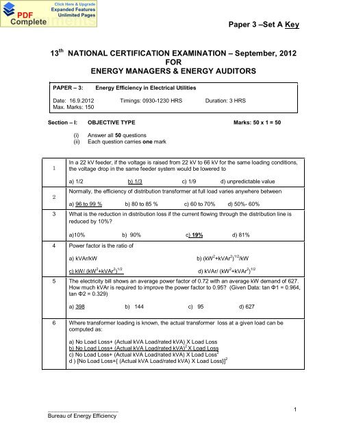
Paper 3 –<strong>Set</strong> A Key<br />
13 th NATIONAL CERTIFICATION EXAMINATION – September, 2012<br />
FOR<br />
ENERGY MANAGERS & ENERGY AUDITORS<br />
PAPER – 3:<br />
<strong>Energy</strong> Efficiency in Electrical Utilities<br />
Date: 16.9.2012 Timings: 0930-1230 HRS Duration: 3 HRS<br />
Max. Marks: 150<br />
Section – I: OBJECTIVE TYPE Marks: 50 x 1 = 50<br />
(i) Answer all 50 questions<br />
(ii) Each question carries one mark<br />
1<br />
In a 22 kV feeder, if the voltage is raised from 22 kV to 66 kV <strong>for</strong> the same loading conditions,<br />
the voltage drop in the same feeder system would be lowered to<br />
2<br />
a) 1/2 b) 1/3 c) 1/9 d) unpredictable value<br />
Normally, the efficiency of distribution trans<strong>for</strong>mer at full load varies anywhere between<br />
a) 96 to 99 % b) 80 to 85 % c) 60 to 70% d) 50%- 60%<br />
3 What is the reduction in distribution loss if the current flowing through the distribution line is<br />
reduced by 10%<br />
a)10% b) 90% c) 19% d) 81%<br />
4 Power factor is the ratio of<br />
a) kVAr/kW b) (kW 2 +kVAr 2 ) 1/2 /kW<br />
c) kW/ (kW 2 +kVAr 2 ) 1/2 d) kVAr/ (kW 2 +kVAr 2 ) 1/2<br />
5 The electricity bill shows an average power factor of 0.72 with an average kW dem<strong>and</strong> of 627.<br />
How much kVAr is required to improve the power factor to 0.95 (Given Data: tan 1 = 0.964,<br />
tan 2 = 0.329)<br />
a) 398 b) 144 c) 95 d) 627<br />
6 Where trans<strong>for</strong>mer loading is known, the actual trans<strong>for</strong>mer loss at a given load can be<br />
computed as:<br />
a) No Load Loss+ (Actual kVA Load/rated kVA) X Load Loss<br />
b) No Load Loss+ (Actual kVA Load/rated kVA) 2 X Load Loss<br />
c) No Load Loss+ (Actual kVA Load/rated kVA) X Load Loss 2<br />
d ) [No Load Loss+{ (Actual kVA Load/rated kVA) X Load Loss}] 2<br />
_______________________<br />
Bureau of <strong>Energy</strong> Efficiency<br />
1
PDF<br />
Documents<br />
Complete<br />
Click Here & Upgrade<br />
Exp<strong>and</strong>ed Features<br />
Unlimited Pages<br />
Paper 3 –<strong>Set</strong> A Key<br />
7 Direct current motors are used in special applications where<br />
a) high torque starting or where smooth acceleration over a broad speed range is required.<br />
b) low torque starting or where steady acceleration over a narrow speed range is required.<br />
c) normal torque starting or where high acceleration over a broad speed range is required.<br />
d) low torque starting or where smooth acceleration over a broad speed range is required.<br />
8 A 3-phase, 415 volts, 50 Hz, 100 kW, 6 pole squirrel cage induction motor with a rated slip of<br />
2% will have a full load rotor speed of<br />
(a) 1470 rpm (b) 980 rpm (c) 1020 rpm (d) none of the above<br />
9 In an induction motor the loss which is independent of motor load<br />
a) I 2 R loss of stator b) I 2 R loss of rotor c) friction <strong>and</strong> windage loss d) all of the above<br />
10 Rewinding can affect which of the following factors that contribute to deterioration in motor<br />
efficiency:<br />
a) winding <strong>and</strong> slot design <strong>and</strong> winding material selection<br />
b) heat applied to strip windings, damage the insulation between laminations, thereby<br />
increasing eddy current losses<br />
c) change in the air gap may affect power factor <strong>and</strong> output torque<br />
d) all the above<br />
11 If measured Line Current of a 3 phase induction motor is 25.98 A, what will be the Phase<br />
Current<br />
a) 15 A b) 45 A c) 8.96 A d) 30 A<br />
12 The efficiency of compressed air system is around<br />
a) 90% b) 60% c) 50% d) 10%<br />
13<br />
The basic function of air dryer in a compressed air system is to<br />
a) remove remaining traces of moisture after the aftercooler<br />
b ) store <strong>and</strong> smoothen pulsating air output<br />
c) reduce the temperature of the air be<strong>for</strong>e it enters the next state to increase efficiency<br />
d) prevent dust from entering compressor<br />
14<br />
Select the correct statement <strong>for</strong> reciprocating air compressors:<br />
a) <strong>for</strong> every 4 o C drop in the inlet air temperature, the increase in energy consumption is by 1%.<br />
b) <strong>for</strong> every 4 o C rise in the inlet air temperature, the decrease in energy consumption is by 1%<br />
c) <strong>for</strong> every 4 o C rise in the inlet air temperature, the increase in energy consumption is by 1%<br />
d) the energy consumption remains same irrespective of inlet air temperature<br />
_______________________<br />
Bureau of <strong>Energy</strong> Efficiency<br />
2
PDF<br />
Documents<br />
Complete<br />
Click Here & Upgrade<br />
Exp<strong>and</strong>ed Features<br />
Unlimited Pages<br />
Paper 3 –<strong>Set</strong> A Key<br />
15<br />
Which of the following parameters is not required <strong>for</strong> evaluating volumetric efficiency of the<br />
compressor<br />
a) FAD b) Cylinder bore diameter c) Stroke length d) Power input<br />
16<br />
Which of the following will not occur if a reciprocating compressor is operated at a lower<br />
discharge pressure<br />
a) lower power consumption<br />
b) less load on the piston rods <strong>and</strong> hence reduced maintenance costs<br />
c) lower leakage losses<br />
d) lower free air delivery than rated<br />
17 Which type of energy efficient dryer can be opted if a user in a plant requires compressed air<br />
at a dew point of -40°C <br />
a) heatless purge type dryer b) heat of compression dryer<br />
c) aftercooler d) refrigerant dryers<br />
18 A 1.5 TR room air conditioner having EER (W/W) of 3.0 , will draw input power of______ kW<br />
a) 1.75 b) 3.00 c) 1.50 d) 2.00<br />
19 Identify the wrong statement from the following regarding Vapour Compression Refrigeration<br />
system<br />
a) condenser rejects heat to atmosphere<br />
b) evaporator removes heat from process or space<br />
c) compressor sends superheated vapor to condenser<br />
d) high pressure sub-cooled liquid refrigerant returns back to evaporator<br />
20 The head developed by a centrifugal pump is not directly proportional to<br />
a) Impeller diameter b) Shaft speed<br />
c) Number of impellers d) Diameter of discharge port<br />
21 Which of the following is incorrect in the case of cooling towers<br />
a)"Range" is the difference between the cooling tower water inlet <strong>and</strong> outlet temperature.<br />
b) "Approach" is the difference between the cooling tower outlet cold water temperature <strong>and</strong><br />
ambient wet bulb temperature.<br />
d)'Range' is a better indicator of cooling tower per<strong>for</strong>mance.<br />
e) Cooling capacity is the heat rejected in kCal/hr or TR<br />
22 Identify the correct statement:<br />
a) the Specific Ratio of Compressors is higher than Blowers<br />
b) the Specific Ratio of Fans is higher than Blowers<br />
c) the Specific Ratio of Compressors is lower than Fans<br />
d) the Specific Ratio of Blowers is higher than Compressors<br />
23 Two energy auditors made following statements regarding Vapour compressor Refrigeration<br />
system <strong>and</strong> what will be your judgement<br />
_______________________<br />
Bureau of <strong>Energy</strong> Efficiency<br />
3
PDF<br />
Documents<br />
Complete<br />
Click Here & Upgrade<br />
Exp<strong>and</strong>ed Features<br />
Unlimited Pages<br />
Paper 3 –<strong>Set</strong> A Key<br />
Statement A: Reducing condensing temperature by 5.5°C, results in a 20 – 25% decrease in<br />
compressor power consumption<br />
Statement B: 5.5°C increase in evaporator temperature reduces compressor power<br />
consumption by 20 – 25%<br />
a) statements A & B are TRUE b) statements A & B are FALSE<br />
c) statement A is TRUE & B is FALSE d) statement A is FALSE & B is TRUE<br />
24 Decreasing the rpm of a fan at partial loading by 10% results in:<br />
25<br />
a) decrease of 10% in flow rate <strong>and</strong> decrease of 27% in power requirement<br />
b) decrease of 10% in flow rate <strong>and</strong> decrease of 19% in power requirement<br />
c) decrease of 10% in flow rate <strong>and</strong> increase of 10% in power requirement<br />
d) increase of 10% in flow rate <strong>and</strong> no appreciable change in power requirement<br />
The power drawn by a centrifugal fan is<br />
a) inversely proportional to fan efficiency b) directly proportional to fan efficiency<br />
c) inversely proportional to static pressure d) inversely proportional to flow rate<br />
26 The frictional loss in a piping system is proportional to<br />
a) flow b) flow 2 c) 1/flow d) 1/flow 2<br />
27 For the same flow, through which of the following diameter pipes, the pump will work with<br />
maximum pressure<br />
a) 100 mm b) 150 mm c) 200 mm d) 250 mm<br />
28 It is possible to run pumps in parallel if their _________________ are similar.<br />
a) suction heads b) discharge heads c) closed valve heads d) none of the above<br />
29 Input power to the motor driving a pump is 20 kW. The motor efficiency is 0.9 <strong>and</strong> pump<br />
efficiency is 0.7. The power transmitted to the water is<br />
a) 12.6 kW b) 18.0 kW c) 14.0 kW d) 31.75 kW<br />
30 Small by-pass lines are installed in pumps some times to _____.<br />
a) increase flow b) control pump delivery head<br />
c) prevent pump running at zero flow d) reduce pump power consumption<br />
31 The refrigeration load in TR when 10 m 3 /hr of water is cooled from a 15 o C to 7 o C is about<br />
a) 10 b) 8 c) 26.5 d) none of the above<br />
32 The order of movement of thermal energy in HVAC system is:<br />
a) Indoor air - Chilled water - Refrigerant-Condenser water- Cooling tower<br />
b) Chilled water - Indoor air - Refrigerant-Cooling tower - Condenser water<br />
c) Indoor air - Condenser water - Chilled water - Cooling tower - Refrigerant<br />
d) Indoor air - Chilled water – Refrigerant - Cooling tower - Condenser water<br />
33 In a cooling tower,<br />
Statement A: Surface of heat exchange is the surface area of the water droplets, which is in<br />
_______________________<br />
Bureau of <strong>Energy</strong> Efficiency<br />
4
PDF<br />
Documents<br />
Complete<br />
Click Here & Upgrade<br />
Exp<strong>and</strong>ed Features<br />
Unlimited Pages<br />
Paper 3 –<strong>Set</strong> A Key<br />
contact with air.<br />
Statement B: Area of heat exchange is the surface area of the fill sheets, which is in contact<br />
with air.<br />
a) statements A & B are false b) statement A is True & B is false<br />
c) statements A & B are True d) statement A is false & B is True<br />
34 If the evaporation loss is 16 m 3 /hr per cell <strong>and</strong> Cycles of Concentration is 3, the blow down<br />
requirement in m 3 /hr per cell of a cooling tower:<br />
a) 8 b) 5.33 c) 4 d) 2<br />
35 Cycles of Concentration (C.O.C) of a cooling tower will depend on<br />
a) TDS in circulating water b) TDS in make-up water<br />
c) both a & b d) none of the above<br />
36 The Solar Heat Gain Coefficient (SHGC) of window of a building is 0.30. This means:<br />
a) That the window allows 70 % of the sun's heat to pass through into interior of the buildings<br />
b) That the window allows 30 % of the sun's heat to pass through into the building<br />
interior<br />
c) That 70 % of the sun's heat is incident on the window<br />
d) That the window reflects back to exterior a minimum of 30 % of the sun's heat<br />
37 FRP fans consume less energy than aluminium fans because<br />
a) they are lighter b) they have better efficiencies<br />
c) they encounter less system resistance d) they deliver less air flow<br />
38 The hydraulic power in a pumping system depends on<br />
a) motor efficiency b) pump efficiency<br />
c) both motor <strong>and</strong> pump efficiency d) none of the above<br />
39 The most energy intensive heat transfer loop of a Vapour Compression Refrigeration System<br />
is:<br />
a) Indoor air loop b) Chilled water loop<br />
c) Refrigerant loop d) Condenser water loop<br />
40 The efficiency of a pump does not depend on<br />
a) suction head b) discharge head c) motor efficiency d) density of fluid<br />
41 The power factor of a squirrel cage induction motor<br />
a) decreases at low motor loading b) decreases at high motor loading<br />
c) remains constant <strong>and</strong> is independent of load d) cannot be predicted<br />
42 The slip of a synchronous motor will be<br />
a) more than the induction motor b) less than the induction motor<br />
c) zero d) load dependent<br />
_______________________<br />
Bureau of <strong>Energy</strong> Efficiency<br />
5
PDF<br />
Documents<br />
Complete<br />
Click Here & Upgrade<br />
Exp<strong>and</strong>ed Features<br />
Unlimited Pages<br />
Paper 3 –<strong>Set</strong> A Key<br />
43 In BEE Star labeled distribution trans<strong>for</strong>mers, which of following losses are defined<br />
a) total loss at 50% <strong>and</strong> 100% loading b) total loss at 75 % loading<br />
c) total loss at 75% <strong>and</strong> 100% loading d) total loss at 100% loading<br />
44 To optimize the voltage level fed to the lighting feeder, the best option is to install.<br />
a) servo stabilizer <strong>for</strong> lighting feeder b) "exclusive" trans<strong>for</strong>mer <strong>for</strong> lighting<br />
c) microprocessor based controllers d) high frequency (HF) electronic ballasts<br />
45 Which one of the following device will help to eliminate the hunting problems normally<br />
associated with capacitor switching<br />
a) Intelligent Power Factor Controller b) maximum dem<strong>and</strong> controller<br />
c) soft starter d) eddy current drives<br />
46 Which one of the following is an incorrect statement<br />
a) fluorescent lamp is an electric discharge lamp<br />
b) electronic ballasts make use of semi-conductor devices<br />
c) electronic ballasts have very low internal loss<br />
d) fluorescent lamps can produce light by direct connection to the power source<br />
47 A 2500 MW super thermal power station generated 15786 million units in the year 2011-12. Its<br />
Plant Load Factor (PLF) is:<br />
a) 60% b) 65% c) 72% d) 79%<br />
48 Which of the following statements is not true of maximum dem<strong>and</strong> controller<br />
a) switches off non-essential loads in Logical sequence.<br />
b) alarm is sounded when dem<strong>and</strong> approaches a preset value.<br />
c) voltage level is closely regulated<br />
d) plant equipment selected <strong>for</strong> the load management can be programmed<br />
49 The main reason <strong>for</strong> using Variable Frequency Drive (VFD) <strong>for</strong> capacity control in electrical<br />
motor driven centrifugal fans with fluctuating load is :<br />
a) improved power quality<br />
b) fan capacity is proportional to its speed whereas the power drawn by the fan is<br />
proportional to the cube of its speed<br />
c) improved power factor<br />
d) precise closed loop process control<br />
50 Select the incorrect statement:<br />
a) harmonics occur as spikes at intervals which are multiples of the supply frequency<br />
b) harmonics are multiples of the fundamental frequency<br />
c) induction motors are the major sources of harmonics<br />
d) trans<strong>for</strong>mers operating near saturation level create harmonics<br />
Section – II: SHORT DESCRIPTIVE QUESTIONS Marks: 8 x 5 = 40<br />
(i) Answer all Eight questions<br />
(ii) Each question carries Five marks<br />
_______________________<br />
Bureau of <strong>Energy</strong> Efficiency<br />
6
PDF<br />
Documents<br />
Complete<br />
Click Here & Upgrade<br />
Exp<strong>and</strong>ed Features<br />
Unlimited Pages<br />
Paper 3 –<strong>Set</strong> A Key<br />
S-1<br />
Ans<br />
List any five industrial applications of a heat pump.<br />
Industrial heat pumps are mainly used <strong>for</strong>:<br />
1. Space heating<br />
2. Heating of process streams<br />
3. Water heating <strong>for</strong> washing, sanitation <strong>and</strong> cleaning<br />
4. Steam production<br />
5. Drying/dehumidification<br />
6. Evaporation<br />
7. Distillation<br />
8. Concentration<br />
S-2 A pump is delivering 64 m 3 /hr of water with a discharge head of 26 metres. The water is drawn<br />
from a sump where water level is 3 metres below the pump centerline. The power drawn by<br />
the motor is 8.89 kW at 88% motor efficiency. Find out the pump efficiency<br />
Ans<br />
Hydraulic power P h = Q (m 3 /s) xTotal head, h d - h s (m) x r (kg/m 3 ) x g (m/s 2 ) / 1000<br />
Q = 64/3600 m 3 /s , h d - h s = 26 – (-3) = 29 m<br />
Hydraulic power P h = (64/3600) x 29 x 1000 x 9.81 / 1000<br />
= 5.0576 kW<br />
Pump shaft power = 8.89 kW x 0.88<br />
= 7.8232 kW<br />
Pump efficiency<br />
= hydraulic power / pump shaft power<br />
= 5.0576 / 7.8232<br />
= 64.65 %<br />
S-3<br />
Ans<br />
S-4<br />
How do the Time-Of-Day (TOD) metering <strong>and</strong> billing benefit the utilities as well as consumers<br />
ToD meter records dem<strong>and</strong>, time, <strong>and</strong> energy <strong>and</strong> the ToD tariff are set in such a way that<br />
higher rates at peak load periods <strong>and</strong> lower rates at off-peak load periods. The billing as per<br />
ToD tariff benefits the consumers to avail maximum power <strong>and</strong> energy at off-peak hours at<br />
lowest tariff ; <strong>and</strong> the higher peak period tariff dis-incentivise <strong>for</strong> increased drawl at peak<br />
period. This results effective maximum dem<strong>and</strong> reduction to the utility, <strong>and</strong> in turn savings in<br />
peak time power procurement at higher rate as well as maximising the load factor <strong>for</strong> resulting<br />
better financials to the utility.<br />
Explain briefly the difference between static <strong>and</strong> dynamic head of a centrifugal pumping<br />
system.<br />
Static head is simply the difference in height of the supply <strong>and</strong> destination reservoirs <strong>and</strong> it is<br />
independent of flow.<br />
Dynamic head is the friction loss, on the liquid being moved, in pipes, valves <strong>and</strong> equipment in<br />
the system. The friction losses are proportional to the square of the flow rate.<br />
_______________________<br />
Bureau of <strong>Energy</strong> Efficiency<br />
7
PDF<br />
Documents<br />
Complete<br />
Click Here & Upgrade<br />
Exp<strong>and</strong>ed Features<br />
Unlimited Pages<br />
Paper 3 –<strong>Set</strong> A Key<br />
S-5<br />
Ans<br />
Compute AT & C (Aggregate Technical <strong>and</strong> Commercial) Losses <strong>for</strong> the following data:<br />
S. No. Description Annual<br />
Data<br />
1 Input <strong>Energy</strong> = (Import-Export), MU 11<br />
2a <strong>Energy</strong> Billed (Metered), MU 7<br />
2b <strong>Energy</strong> Billed (Un-Metered), MU 1<br />
2c Total <strong>Energy</strong> Billed 8<br />
3 Amount Billed (Rs. lakhs ) 450<br />
4a Gross Amount Collected (Rs. lakhs) 460<br />
4b Arrears Collected (Rs. lakhs) 40<br />
Estimation of AT & C Losses<br />
S. No. Description Annual<br />
Data<br />
1 Input <strong>Energy</strong> = (Import-Export), MU Ei 11<br />
2a <strong>Energy</strong> Billed (Metered), MU E1 7<br />
2b <strong>Energy</strong> Billed (Un-Metered), MU E2 1<br />
2c Total <strong>Energy</strong> Billed ( E1 + E2 ) Eb 8<br />
3 Amount Billed (Rs. lakhs ) Ab 450<br />
4a Gross Amount Collected (Rs. lakhs) AG 460<br />
4b Arrears Collected (Rs. lakhs) Ar 40<br />
4c Amount Collected without Arrears (Rs. lakhs) Ac=AG-Ar 420<br />
5 Billing Efficiency (BE) = Eb/Ei *100% 72.7%<br />
6 Collection Efficiency(CE) =Ac/Ab *100% 93.3%<br />
7 AT& C Loss {1- (BE *CE )<br />
*100%<br />
32.17%<br />
S-6<br />
A DG set is operating at 700 kW load with 450 O C exhaust gas temperature. The DG set<br />
generates 7.8 kg of exhaust gas/ kWh generated. The specific heat of gas at 430 o C is 0.25<br />
kCal/ kg O C. A heat recovery boiler is installed after which the exhaust temperature drops to<br />
220 O C. How much steam will be generated at 3 kg/ cm 2 with enthalpy of 650.57 kcal/ kg.<br />
Assume boiler feed water temperature as 65 o C.<br />
Ans<br />
= 700 kWh x 7.8 kg gas generated/ kWh output x 0.25 kCal/ kg o C x (450 o C-220 o C) =3,13,950<br />
kCal/hr<br />
Steam generation = 3,13,950 kCal/hr / (650.57 – 65) = 536.14 kg/ hr.<br />
S-7<br />
An energy audit of a fan was carried out. It was observed that the fan was delivering 18,500<br />
Nm 3 /hr of air with static pressure rise of 45 mm WC. The power measurement of the 3-phase<br />
induction motor coupled with the fan recorded 2.9 kW/ phase on an average. The motor<br />
operating efficiency was assessed as 88% from the motor per<strong>for</strong>mance curves. What would<br />
be the fan static efficiency<br />
Ans<br />
Q = 18,500 Nm 3 / hr.= 5.13888 m 3 /sec ,<br />
SP = 45 mmWC,<br />
η St = ,<br />
_______________________<br />
Bureau of <strong>Energy</strong> Efficiency<br />
8
PDF<br />
Documents<br />
Complete<br />
Click Here & Upgrade<br />
Exp<strong>and</strong>ed Features<br />
Unlimited Pages<br />
Paper 3 –<strong>Set</strong> A Key<br />
Power input to motor= 2.9x3=8.7 kW<br />
Power input to fan shaft=8.7 x0.88=7.656 kW<br />
Fan static η =<br />
Volume in m 3 /sec x ∆P st in mmWc<br />
102 x Power input to shaft<br />
= 5.13888 x 45<br />
102 x 7.656<br />
= 0.296<br />
= 29.6%<br />
S-8<br />
List down any 5 energy conservation opportunities in compressed air system<br />
Ans<br />
• Ensure air intake to compressor is not warm <strong>and</strong> humid by locating compressors<br />
in well-ventilated area or by drawing cold air from outside. Every 4 0 C rise in air<br />
inlet temperature will increase power consumption by 1 percent.<br />
• Clean air-inlet filters regularly. Compressor efficiency will be reduced by 2 percent<br />
<strong>for</strong> every 250 mm WC pressure drop across the filter.<br />
• Keep compressor valves in good condition by removing <strong>and</strong> inspecting once every<br />
six months. Worn-out valves can reduce compressor efficiency by as much as 50<br />
percent.<br />
• Install manometers across the filter <strong>and</strong> monitor the pressure drop as a guide to<br />
replacement of element.<br />
• Minimize low-load compressor operation; if air dem<strong>and</strong> is less than 50 percent of<br />
compressor capacity, consider change over to a smaller compressor or reduce<br />
compressor speed appropriately (by reducing motor pulley size) in case of belt<br />
driven compressors.<br />
• Consider the use of regenerative air dryers, which uses the heat of compressed<br />
air to remove moisture.<br />
• Fouled inter-coolers reduce compressor efficiency <strong>and</strong> cause more water<br />
condensation in air receivers <strong>and</strong> distribution lines resulting in increased<br />
corrosion. Periodic cleaning of inter-coolers must be ensured.<br />
• Compressor free air delivery test (FAD) must be done periodically to check the<br />
present operating capacity against its design capacity <strong>and</strong> corrective steps must<br />
be taken if required.<br />
• If more than one compressor is feeding to a common header, compressors must<br />
be operated in such a way that only one small compressor should h<strong>and</strong>le the load<br />
variations whereas other compressors will operate at full load.<br />
Any other relevant point<br />
-------- End of Section II ---------<br />
_______________________<br />
Bureau of <strong>Energy</strong> Efficiency<br />
9
PDF<br />
Documents<br />
Complete<br />
Click Here & Upgrade<br />
Exp<strong>and</strong>ed Features<br />
Unlimited Pages<br />
Paper 3 –<strong>Set</strong> A Key<br />
Section – III: LONG DESCRIPTIVE QUESTIONS Marks: 6 x 10 = 60<br />
(i) Answer all Six questions<br />
(ii) Each question carries Ten marks<br />
L-1<br />
Ans<br />
a) In a cooling tower, the cooling water circulation rate is 1200 m 3 /hr. The water enters the<br />
cooling tower at 38 o C. The ambient wet bulb temperature is 26 o C. The cooling tower operates<br />
with an approach of 4 o C. If the blowdown rate of the cooling tower is 1 % of the circulation<br />
rate, calculate the evaporation loss <strong>and</strong> COC.<br />
b) A medium scale industry has a load of 450 kVA. It has installed two trans<strong>for</strong>mers of 500<br />
kVA each. The no load loss <strong>and</strong> full load copper loss are 760 W <strong>and</strong> 5400 W respectively.<br />
From the energy efficiency point of view the management wants to take a decision on whether<br />
to operate a single trans<strong>for</strong>mer on full load or two trans<strong>for</strong>mers equally sharing the load. What<br />
is your recommendation Why<br />
a) Leaving cold water temperature = 26 + 4 = 30 o C<br />
Evaporation Loss (m 3 /hr) = 0.00085 x 1.8 x circulation rate (m 3 /hr) x (T 1 –T 2 )<br />
= 0.00085 x 1.8 x 1200 x 8<br />
= 14.69 m 3 /hr<br />
Blowdown<br />
= 12 m 3 /hr<br />
Blowdown = Evaporation loss / (COC – 1)<br />
12 = 14.69 / (COC – 1)<br />
COC = 2.224<br />
b)<br />
1 x 500 kVA<br />
Trans<strong>for</strong>mer loss at 450<br />
No load loss + [kVA load/Rated kVA] 2 x full<br />
load loss<br />
760 + 4374<br />
5134 W<br />
2 x 500 at 50% load 2 x {760 + [225/500] 2 x 5400}<br />
3707 W<br />
Two trans<strong>for</strong>mers are better because the losses are the least.<br />
_______________________<br />
Bureau of <strong>Energy</strong> Efficiency<br />
10
PDF<br />
Documents<br />
Complete<br />
Click Here & Upgrade<br />
Exp<strong>and</strong>ed Features<br />
Unlimited Pages<br />
Paper 3 –<strong>Set</strong> A Key<br />
L-2<br />
Fill in the blanks <strong>for</strong> the following<br />
1. A motor which can conveniently be operated at lagging as well as leading power<br />
factors is the___________ motor<br />
2. A 50 Hz, 3-phase induction motor has a full load speed of 1440 r.p.m. The number of<br />
poles of the motor are______<br />
3. In a centrifugal pump the velocity energy is converted to pressure energy by _____<br />
4. In a centrifugal pump if the liquid to be pumped has density twice that of water, then<br />
the horse power required (as compared to that while pumping water) will be______<br />
times<br />
5. The friction loss in a pipe carrying a fluid is proportional to the fifth power of<br />
_________<br />
6. A 10 MVA generator has power factor 0.866 lagging. The reactive power produced will<br />
be ______ MVAR<br />
7. Totally-enclosed, fan cooled (TEFC) motors are______ efficient than Screen –<br />
protected, drip-proof (SPDP) induction motors<br />
8. Low speed Squirrel cage induction motors are normally ______efficient than high<br />
speed squirrel cage induction motors<br />
9. Harmonics in electricity supply are multiples of the ________frequency<br />
10. For the same rating, slip ring induction motors are normally _________efficient than<br />
squirrel cage induction motors<br />
Ans<br />
1. Synchronous<br />
2. 4<br />
3. volute or diffuser<br />
4. 2<br />
5. pipe diameter<br />
6. 5<br />
7. more<br />
8. less<br />
9 fundamental<br />
10 less<br />
L-3 a) Calculate the free air delivery (FAD) in m 3 /min of a compressor <strong>for</strong> the following observed<br />
data:<br />
Receiver capacity: 0.25 m 3<br />
Initial pressure:<br />
Final pressure:<br />
Initial temperature:<br />
Final temperature:<br />
1 kg/cm 2 (g)<br />
7 kg/cm 2 (g)<br />
32 o C<br />
52 o C<br />
Additional holdup volume: 0.05 m 3<br />
Compressor pump up time: 2.1 minutes<br />
b) Identify the following statements as applicable to Vapor Compression Refrigeration System<br />
_______________________<br />
Bureau of <strong>Energy</strong> Efficiency<br />
11
PDF<br />
Documents<br />
Complete<br />
Click Here & Upgrade<br />
Exp<strong>and</strong>ed Features<br />
Unlimited Pages<br />
Paper 3 –<strong>Set</strong> A Key<br />
(VCR) or to Vapor Absorption Refrigeration System(VAR).<br />
Ans<br />
I. The system operates under vacuum - ________(VCR/VAR)<br />
II. Uses water as a refrigerant - ________(VCR/VAR)<br />
III. Uses large amount of high-grade energy - ________(VCR/VAR)<br />
IV. COP decreases considerably with decrease in evaporator pressure -<br />
________(VCR/VAR)<br />
V. The system can work on lower evaporator pressures also without affecting the COP -<br />
________(VCR/VAR)<br />
Q =<br />
P2<br />
− P1<br />
V ⎛ 273 + t<br />
× ×<br />
⎜<br />
P0<br />
t ⎝ 273 + t<br />
1<br />
2<br />
⎞<br />
⎟<br />
⎠<br />
7 −1<br />
(0.25+<br />
0.05)<br />
=<br />
⎛ 273+<br />
32 ⎞<br />
×<br />
× ⎜ ⎟<br />
1.026 2.1 ⎝ 273+<br />
52 ⎠<br />
= 0.784 m 3 /min<br />
I. The system operates under vacuum VAR<br />
II. Uses water as a refrigerant VAR<br />
III. Using large amount of high-grade energy VCR<br />
IV. The COP decreases considerably with decrease in evaporator pressure. VCR<br />
V. The system can work on lower evaporator pressures also without affecting the COP<br />
VAR<br />
L-4<br />
The measured values of a water cooled 20 TR package air conditioning plant are given<br />
below:<br />
Average air velocity across suction side filter: 2.5 m/s<br />
Cross Sectional area of suction: 2.4 m 2<br />
Inlet air : Dry Bulb:20 deg. C, Wet Bulb: 14 deg. C; Enthalpy: 9.37 k Cal per kg<br />
Outlet air: Dry Bulb: 12.7 deg. C, Wet Bulb: 11.3 deg. C; Enthalpy: 7.45 k Cal per kg<br />
Specific volume of Air: 0.85 m 3 /kg<br />
Power drawn: by Compressor : 18.42 k W<br />
by Pump : 2.1 k W<br />
by Evaporator Fan : 1.25 k W<br />
Calculate the following:<br />
i. Air Flow rate<br />
ii. Cooling effect delivered<br />
iii. Compressor kW/TR<br />
iv. Overall kW/TR<br />
v. Overall <strong>Energy</strong> Efficiency ratio in W/W<br />
Ans<br />
i. Air flow rate = 2.5*2.4 = 6 m 3 /sec = 21600 m 3 /hr<br />
ii. Cooling Effect delivered = [(9.37-7.45)*21600]/(0.85*3024) = 16.13 TR = 56.73 kW<br />
iii. Compressor kW/TR = 18.42 /16.13 = 1.13<br />
iv. Overall kW/TR = (18.42+2.1+1.25)/16.13 = 1.35<br />
v. <strong>Energy</strong> Efficiency Ratio(EER) in W/W = 56.73/21.77 = 2.606<br />
_______________________<br />
Bureau of <strong>Energy</strong> Efficiency<br />
12
PDF<br />
Documents<br />
Complete<br />
Click Here & Upgrade<br />
Exp<strong>and</strong>ed Features<br />
Unlimited Pages<br />
Paper 3 –<strong>Set</strong> A Key<br />
L-5<br />
a) How do you calculate the velocity of air/gas in a duct using the average differential<br />
pressure <strong>and</strong> density of the air/gas<br />
b) A no load test was conducted in a delta connected 37 kW induction motor.<br />
Nameplate data- 3 Phase, 415 V, 50 Hz, 55 Amp<br />
Measured data at no load:<br />
Voltage, V = 415 Volts; Current, I = 17 Amps; Frequency, F = 50 Hz;<br />
Stator phase resistance at 30°C = 0.24 Ohms/ phase<br />
No load power = 955 Watts<br />
i. Find out Iron Loss plus Friction Loss plus Windage Loss<br />
ii. Stator Copper Loss at name plate ratings(full load), considering stator temperature<br />
=120 °C<br />
iii. No load power factor of the motor<br />
Ans<br />
a) Ans:<br />
Velocity V, m/s = C P x (2 x 9.81 p x y) 1/2<br />
y<br />
<br />
<br />
C p<br />
= Pitot tube constant, 0.85 (or) as given by the manufacturer<br />
p = Average differential pressure measured by pitot tube by taking<br />
measurement at number of points over the entire cross section of the duct.<br />
= Density at air/ gas at test condition<br />
b) Let Iron Loss plus Friction Loss plus Windage Loss be P i +fw<br />
Stator Copper Loss, P st , 30°C = 3X (17/3) 2 X0.24 = 69.36 Watt<br />
P i +fw = P nl - P st = 955 – 69.36 = 885 .64<br />
Stator resistance at 120 °C = 0.24x[(120+235)/[(30+235)] = 0.322 Ohms<br />
Stator Copper Loss at name plate ratings = 3x(55/3) 2 X0.322 = 974.05 Watt<br />
No load power factor= 955/(1.7321x415x17)=0.078<br />
L-6<br />
Answer any two of the following :<br />
(i) two most important electrical parameters, which are to be monitored <strong>for</strong> safe<br />
operation of Diesel Generator set<br />
(ii) Slip method of motor load assessment<br />
(iii) Five options <strong>for</strong> electricity distribution loss optimization<br />
(iii) Five energy conservation opportunities in pumping system<br />
Ans (i) two most important electrical parameters, which are to be monitored <strong>for</strong> safe<br />
operation of Diesel Generator set are KVA <strong>and</strong> kW<br />
(ii)<br />
Slip method of motor load assessment<br />
In the absence of a power meter, the slip method can be used which requires a tachometer.<br />
The percentage loading can be calculated as follows:<br />
_______________________<br />
Bureau of <strong>Energy</strong> Efficiency<br />
13
PDF<br />
Documents<br />
Complete<br />
Click Here & Upgrade<br />
Exp<strong>and</strong>ed Features<br />
Unlimited Pages<br />
Paper 3 –<strong>Set</strong> A Key<br />
Slip<br />
Load = *100%<br />
Ss−<br />
Sr<br />
Where:<br />
Load = Output power as a % of rated power<br />
Slip = Synchronous speed - Measured speed in rpm<br />
S s = Synchronous speed in rpm at the operating frequency<br />
S r = Nameplate full-load speed<br />
Slip also varies inversely with respect to the motor terminal voltage squared. A voltage<br />
correction factor can, also, be inserted into the slip load equation. The voltage<br />
compensated load can be calculated as shown<br />
Where:<br />
Load = Output power as a % of rated power<br />
Slip = Synchronous speed - Measured speed in rpm<br />
S s = Synchronous speed in rpm<br />
S r = Nameplate full-load speed<br />
V = RMS voltage, mean line to line of 3 phases<br />
V r = Nameplate rated voltage<br />
iii) Five options <strong>for</strong> electricity distribution loss optimization<br />
• minimising length of distribution lines<br />
• adequate Size of Conductors<br />
• installaing Distribution Trans<strong>for</strong>mers (DTR) at load center on the Secondary<br />
Distribution System<br />
• Maintaining high Power Factor<br />
• High Voltage Distribution System (HVDS)<br />
• Incorporating Amorphous Core Trans<strong>for</strong>mers<br />
Any other relevant point<br />
iv) Five energy conservation opportunities in pumping system<br />
• Ensure adequate NPSH at site of installation<br />
• Operate pumps near best efficiency point.<br />
• Modify pumping system/pumps losses to minimize throttling.<br />
• Adapt to wide load variation with variable speed drives<br />
• Stop running multiple pumps - add an auto-start <strong>for</strong> an on-line spare or add a<br />
booster pump in the problem area.<br />
• Conduct water balance to minimise water consumption<br />
• Replace old pumps by energy efficient pumps<br />
Any other relevant point<br />
. End of Section III <br />
_______________________<br />
Bureau of <strong>Energy</strong> Efficiency<br />
14