Carbon fibre reinforced laminates Bonded steel ... - Siegwart, Michael
Carbon fibre reinforced laminates Bonded steel ... - Siegwart, Michael
Carbon fibre reinforced laminates Bonded steel ... - Siegwart, Michael

You also want an ePaper? Increase the reach of your titles
YUMPU automatically turns print PDFs into web optimized ePapers that Google loves.
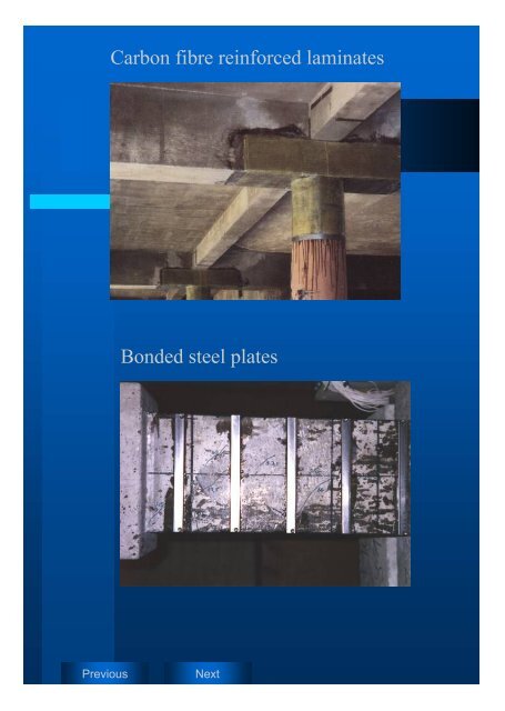
<strong>Carbon</strong> <strong>fibre</strong> <strong>reinforced</strong> <strong>laminates</strong><br />
<strong>Bonded</strong> <strong>steel</strong> plates<br />
Previous<br />
Next
UNIVERSITY OF ULSTER<br />
- Jordanstown -<br />
School of the Built Environment<br />
Introduction<br />
INTRODUCTION<br />
A building has to withstand various loads, e.g. the normal vertical loads from its weight,<br />
different load combinations, etc.. In addition, tall buildings are under attack from lateral<br />
forces caused by wind and earthquakes or other catastrophic impacts. Buildings are stiffened<br />
by means of structural elements such as shear walls. These walls are placed in form of a core<br />
to provide additional stiffness against lateral forces.<br />
In order to transform the forces that act on shear walls with openings, they are connected by<br />
means of coupling beams (coupled shear wall system). When a building with a coupled shear<br />
wall system is under attack by seismic forces, the energy is dissipated along the core of<br />
coupled shear walls by means of plastic hinges, which occur either in the beam or in the joint<br />
to the shear wall. After the seismic event, the beams can be repaired in order to restore the<br />
structural integrity of the building (Figure 1).<br />
The report presents the effectiveness of structural repair methods such as resin injection, plate<br />
bonding and glass <strong>fibre</strong>s. To do so, five full-scale concrete specimens, half of a coupled shear<br />
wall system, were produced and overloaded. Three of them were repaired by of means resin<br />
injection and structurally strengthened using externally bonded <strong>steel</strong> shear strips, <strong>steel</strong> plates<br />
and glass <strong>fibre</strong> <strong>laminates</strong>. After a curing period they were reloaded. Their behaviour was<br />
recorded and is presented and analysed in this report.<br />
<strong>Michael</strong> <strong>Siegwart</strong> 1
UNIVERSITY OF ULSTER<br />
- Jordanstown -<br />
School of the Built Environment<br />
Background Knowledge<br />
BACKGROUND KNOWLEDGE<br />
SHEAR WALLS<br />
Shear walls in seismic regions show good behaviour when seismic forces attack a building<br />
since they take and dissipate horizontal shear forces. They prevent buildings from collapsing<br />
during strong earthquakes and also avoid or limit structural damage when the applied seismic<br />
disturbance is moderate. Structures such as shear walls ensure that in the event of earthquakes<br />
human lives are protected, damage is limited and structures important for civil protection<br />
remain operational [8] . Different types of shear walls can be determined according to their<br />
design. The types are cantilever shear walls, coupled shear walls and slit shear walls (Figure<br />
4).<br />
The ultimate strength of such coupled shear walls is reached when a collapse mechanism is<br />
formed within the system. The collapse mechanism occurs when two plastic hinges develop in<br />
each coupling beam and one plastic hinge in each cantilever wall (at their base) is generated<br />
due to the subjected lateral load (Figure 3Figure 4, Figure 5). The sequence of hinge<br />
formation in a structure depends on the relative strength and stiffness of its components.<br />
STRENGTH AND BEHAVIOUR OF COUPLING BEAMS<br />
The deformation of the coupling beams is a combination of shear (Figure 8) and flexure<br />
(Figure 7). The actions of a beam where shear and flexural stress are subjected is complex<br />
(Figure 9). There are two different types of behaviour. Firstly, where flexural action governs<br />
over shear action the behaviour is similar to the behaviour of beams that are only subjected to<br />
flexural stress. The second type, where shear stress governs, is more complex. The flexural<br />
deformations that cause a double curvature of the beam and consequently tension along one<br />
side and stress on the other half, conflict with the shear deformation, which puts the beam into<br />
tension along both surfaces [31] . At the early state of loading the beam deforms in a flexural<br />
load manner with a double curvature and a line of contraflexure at the centre of the span.<br />
When the shear is strong enough to initiate a diagonal crack, the flexural behaviour changes.<br />
A shift of the points of contraflexure from the midspan towards the supports in the opposite<br />
direction occurs. Hence, the line of contraflexure rotates anticlockwise as the diagonal crack<br />
<strong>Michael</strong> <strong>Siegwart</strong> 2
UNIVERSITY OF ULSTER<br />
- Jordanstown -<br />
School of the Built Environment<br />
Background Knowledge<br />
in the concrete progresses. The shift of the points of contraflexure will stop near the end<br />
supports. At the end supports the conflicting forces of shear and flexure causes the<br />
reinforcement to kink. The maximum load-carrying capacity of the concrete is reached when<br />
small parts of concrete in the compression corners of the beam crush.<br />
REPAIR OF CONCRETE STRUCTURES<br />
Although concrete is a material which provides high durability and resistance against<br />
aggressive environmental factors, concrete structures undergo some damage due to physical<br />
impact or environmental attack and therefore need to be repaired. Damage might occur<br />
because of the following reasons: cracks in concrete, high permeability or high porosity,<br />
insufficient cover, carbonation and chloride, abrasion, freeze thaw, thermal shock, fire<br />
damage, high velocity waters, overloading, chemical reactions and alkali-silica reaction.<br />
Two basic types of repair work can be classified. The structural repair and the non-structural<br />
repair (Figure 11). The aim of any concrete repair is to protect the reinforcement from further<br />
corrosion, to enhance or restore the appearance of the structure, and to restore or increase the<br />
load carrying capacity. The selected repair method must provide durable repair within an<br />
acceptable cost range.<br />
Deep cracks in massive concrete members and cracks, which pass through a member, can be<br />
repaired by crack injection using a selected polymer such as epoxy resin. It is very important<br />
that the work is carried out carefully since inadequately repaired cracks cannot be repaired for<br />
a second time. Once epoxy has filled the cracks, it will rest there and cannot be removed any<br />
more. The resin is suitable to restore the structure to its original strength and stiffness [1] .<br />
The strengthening of beams by means of epoxy-bonded <strong>steel</strong> or composite plates is widely<br />
used. A major shortcoming of the system is the corrosion of the plates since the surface is<br />
fully exposed to the environment. An alternative to <strong>steel</strong> plates is therefore the bonding of<br />
<strong>reinforced</strong> plastics, which do not corrode. Other basic advantages are their low weight, which<br />
makes installation very easy and their greater length since the need for lapping at joints is<br />
eliminated. The material can be pre-stressed [20] and is fire resistant. [11] . On the other hand the<br />
material is relatively costly compared to <strong>steel</strong>.<br />
<strong>Michael</strong> <strong>Siegwart</strong> 3
UNIVERSITY OF ULSTER<br />
- Jordanstown -<br />
School of the Built Environment<br />
Research<br />
EXPERIMENTAL PROGRAM<br />
SAMPLES<br />
The test specimens were designed as a part of a coupled shear wall that is connected by beams<br />
and cut in the midspan of the beam. The samples exist as a part of a shear wall that has<br />
dimensions of 1000mm in width, 150mm in depth, and 1200mm in height. The wall parts of<br />
all five samples were <strong>reinforced</strong> with 16mm high yield <strong>steel</strong> bars in the longitudinal direction,<br />
and with binders in 6mm of diameter @ 120mm. The ends of the wall contained a column<br />
reinforcement in order to dissipate the expected forces and to limit the failure on the beam.<br />
The concrete was designed f cu = 50 N/mmÄ. [7] Two different dimensions of coupling beams<br />
were produced. Two samples, Sample 1-40 and Sample 2-40 had a beam height of 40 cm, a<br />
length of 80 cm and a width of 15 cm (Figure 13). Sample 1-30, Sample 2-30 and Sample 3-<br />
30 had a beam height of 30 cm whilst the other dimensions were the same (Figure 12 and<br />
Table 1).<br />
TEST SET-UP<br />
Adjustable stanchions were placed on the surface of the shear wall section of the specimen.<br />
They supported the specimens vertically. Horizontal support was provided by means of three<br />
different mechanisms. First, an adjustable stanchion was placed horizontally at the top of the<br />
shear wall section and screwed onto a vertical rack stanchion. Second, a clamping mechanism<br />
that pulled the shear wall on the same vertical rack stanchion was applied at the bottom. And<br />
third, a pushing mechanism was applied to the bottom of the shear wall by means of two long<br />
adjustable <strong>steel</strong> beams. The load was applied by using a hydraulic jack with 700mm clearance<br />
from the wall. Underneath the jack, a 200 kN load cell was installed. To monitor the<br />
movements and deflections three dial gauges were installed along the surface of the specimen<br />
(Figure 15).<br />
<strong>Michael</strong> <strong>Siegwart</strong> 4
UNIVERSITY OF ULSTER<br />
- Jordanstown -<br />
School of the Built Environment<br />
Research<br />
REPAIR<br />
Sample 1-40 and Sample 2-40 could not be repaired since the achieved crack opening was too<br />
small due to the failure of the supporting rack. Samples 1-30 to 2-30 were repaired by means<br />
of resin injection in the failure cracks. Thereafter <strong>steel</strong> shear strips, <strong>steel</strong> shear plates and glass<br />
fibers were externally bonded onto the beams to strengthen them.<br />
RESIN INJECTION<br />
The tension and shear cracks were injected using TamRez 210 . Before the cracks were<br />
sealed the surface area around them was cleaned mechanically. Thereafter, holes were drilled<br />
along the major cracks at distance of approximately 10 cm. The sealant (TamRez 310) was<br />
placed over the cleaned area. Tam plastic injection ports were then glued, using TamRez<br />
310, over the drilled holes (Figure 14). The bond of the injection ports to the concrete failed<br />
during the injection process after about 40 seconds, although the pressure was only 3 bar. The<br />
resin came out of small cracks around the injection ports. The degree of filling by the resin is<br />
therefore assumed to be very low and mainly dependent upon capillary effects rather than<br />
injection pressure. An investigation of the specimen using the ultrasonic method, in order to<br />
prove filling of cracks, did not succeed.<br />
PLATE BONDING<br />
Sample 1-30 was the strengthened by means of two shallow shear plates that were bonded on<br />
the surface of both sides of the beam by means of TamRez 220. To achieve adequate bond<br />
the plates were pressed onto the surface of the sample using weights until the resin was cured<br />
(Figure 16, Figure 17).<br />
Sample 2-30 was strengthened against shear failure using shear strips. The strips were placed<br />
above the surface using a cover meter in the same spacing of 120 mm. The joint to the shear<br />
wall was covered by means of T-shaped <strong>steel</strong> plates The dimensions were 30 mm x 300 mm<br />
for the beam section and 45 mm x 500 mm for the wall section. The plate thickness was 3<br />
mm. The <strong>steel</strong> was the same as used for the shear strips (Figure 18).<br />
<strong>Michael</strong> <strong>Siegwart</strong> 5
UNIVERSITY OF ULSTER<br />
- Jordanstown -<br />
School of the Built Environment<br />
Research<br />
Sample 3-30 was strengthened using the Tyfo Fibrwrap System. Two layers of glass<br />
<strong>fibre</strong>s (TyfoS / SEH) were wrapped around the beam section. The joint was strengthened<br />
using two layers of Tyfo BC. The glass <strong>fibre</strong>s were pre-cut and manually saturated by<br />
means of epoxy resin Tyfo S. The dimensions of the T-shaped Tyfo BC layers were 100<br />
mm x 500 mm bonded to the shear wall section and 100 mm x 300 mm bonded to the beam<br />
section of the specimen (Figure 19).<br />
The installation was carried out according the proposal of Fyfe Co. LLC, USA. The beam was<br />
wrapped in such a way that both sides and the underside were covered by the TyfoS / SEH<br />
glass <strong>fibre</strong>s. The surface was not covered in order to simulate a non-accessible surface. The<br />
<strong>fibre</strong>s were allocated vertical direction in order to strengthen against shear failure. Therefore<br />
the effect of the layers bonded onto the underside (flexure) is likely to be marginal. The<br />
Tyfo BC glass <strong>fibre</strong>s are allocated in a grid of 45 degrees inclined against the horizontal in<br />
each direction in order to transfer the forces from the beam to the shear wall. The thickness of<br />
one layers (Tyfo BC and TyfoS / SEH) was approximately 1 mm. Before the glass <strong>fibre</strong>s<br />
were installed the surface of the specimen was cleaned using a needle gun. Dirt and dust was<br />
removed by means of vacuum cleaning. The surface was coated using the epoxy resin Tyfo<br />
S before the glass <strong>fibre</strong>s were bonded onto the specimen. After one day, the saturated <strong>fibre</strong>s<br />
were bonded onto the surface. The <strong>fibre</strong>s were not anchored. Due to the nature of the<br />
installation process, which does not require any clamping of the bonded material, the<br />
specimen was repaired in its testing position.<br />
EXPERIMENTAL RESULTS<br />
Sample 1-30<br />
The main cracks during the first test were a tension crack in the joint to the shear wall and a<br />
diagonal shear crack in the beam section (Figure 20). The crack width reached during the first<br />
test is very small. Only crack 13 reached a width of 0,2 mm at a load of 73 kN. The vertical<br />
displacement is high compared to Sample 2-30 and Sample 3-30. The sample was repaired by<br />
means of an externally bonded shear plate. The repair was effective although the calculated<br />
load capacity was not reached since the joint to the shear wall failed at a load of 84 kN. No<br />
cracks occurred until the load of 42 kN was reached then a flexural crack opened at a distance<br />
<strong>Michael</strong> <strong>Siegwart</strong> 6
UNIVERSITY OF ULSTER<br />
- Jordanstown -<br />
School of the Built Environment<br />
Research<br />
of 15 cm from the shear wall section until the shear plate was reached. The crack opened at a<br />
place that was previously undamaged. The reason for this is the difference in the initial<br />
stiffness due to the shear plate. However, as the load increased to 48 kN hairline cracks<br />
appeared at the border to the <strong>steel</strong> plate in the lower part of the T-shaped end section of the<br />
shear plate in the resin layer. The cracks were found from the middle axis downwards. No<br />
other cracks developed. The sample failed suddenly at a load of 84 kN. The failure occurred<br />
in the concrete. The bond of the plate to the concrete did not fail (Figure 22). The ultimate<br />
capacity of the reference sample (sample 3-30) was reached at a load of 80 kN. The test of<br />
sample 1-30 was stopped at a load of 74 kN.<br />
Sample 2-30<br />
The first crack, crack 1 occurred at a load of 28 kN at the joint to the shear wall. This crack<br />
proceeded further as the load increased and reached its final length of 25 cm at a load of 42<br />
kN. The crack opened wider as the load increased. The crack width was 0,6mm at a load of 71<br />
kN. The early occurrence of a tension crack in the shear wall can be put down to the fact of a<br />
much stiffer test set-up as for sample 1-30. However at 30 kN two further cracks, crack 2 and<br />
crack 3 occurred. Crack 2 stopped to increase at a load of 56 kN. The crack opening was<br />
between 0,1 mm and 0,2 mm. Crack 3 increased until 60 kN were reached. At this load stage<br />
a 12 cm long shear crack grew of crack 3 towards the bottom face of the beam. At a load of<br />
50 kN the last tension crack, crack 5 developed from the bottom face of the beam. This crack<br />
did not increase any further. As the load increased by 2 kN to 52 kN the diagonal shear crack,<br />
crack 6, started to develop. It stopped at a load of 70 kN at a distance of 3 cm from the top<br />
face of the beam. As the load increased to 72 kN spalling of the concrete cover occurred at<br />
crack 6 in the middle axis of the beam. The slope of the test graph became 0 so that the test<br />
was stopped. The displacement of the beam increased at a load of 30 kN from 2,5 mm to 6<br />
mm. This was due to the uplift of the supporting rack due to the insufficient lateral support of<br />
the shear wall section.<br />
Sample 2-30 was externally <strong>reinforced</strong> by means of high yield <strong>steel</strong> strips for shear. Although<br />
the dimensions of the shear strips were small compared to the shear plate of sample 1-30, the<br />
repair was successful. A flexural crack occurred between the joint plate and the first shear<br />
strip of the beam section at a load of 26 kN. It increased to a length of 15 cm as the load was<br />
<strong>Michael</strong> <strong>Siegwart</strong> 7
UNIVERSITY OF ULSTER<br />
- Jordanstown -<br />
School of the Built Environment<br />
Research<br />
increased to 34 kN. When the load reached 56 kN the crack width between the T-plate and the<br />
shear strip increased further.<br />
The original shear crack (crack 6) that was repaired by means of resin injection reopened at a<br />
load of 60 kN. This did not affect the performance of the beam since the stiffness did not<br />
decrease. The failure occurred at a load of 82 kN. The initial crack between the joint plate and<br />
the first shear strip increased in its length. It stopped 5 cm from the top face of the beam. The<br />
opening of the crack was 3 mm (Figure 23).<br />
Sample 3-30<br />
The tension crack in the joint of the beam occurred at a load of 22 kN. It increased until a load<br />
of 30 kN was reached. The crack length was 20 cm at this load stage. As the load increase the<br />
crack width increased to 1 mm at 72 kN. Cracks 2, 3, 4 and 5 occurred at 40 kN. Crack 3 did<br />
not proceed any further as its initial length of 7 cm. Crack 2 did not proceed further as well.<br />
At a load of 48 kN crack 4 reached its final length of 14 cm and crack 6 occurred. As the load<br />
increased to 68 kN the crack length of crack 6 increased to its final length of 25 cm. The<br />
diagonal shear crack occurred at a load of 52 kN and reached its final length of 40 cm at a<br />
load of 62 kN. The crack opened wider as the load increased. It reached a width of 1mm. At a<br />
load of 80 kN the sample failed at the beam joint to the shear wall and the slope of the test<br />
graph became zero. The early occurrence of a tension crack in the shear wall can be put down<br />
to the fact that there was very effective lateral support. As the load was taken away the cracks<br />
closed and were only visible as hairline cracks on the surface of the beam. The crack at the<br />
joint and the shear crack (crack 1 and crack 7) did not, however, close as far. The crack<br />
opening of the latter cracks after the load was taken away were 0,5mm. Sample 3-30 was the<br />
only specimen that reached a wide opening of cracks at its failure load.<br />
It was repaired by means of wrapped glass <strong>fibre</strong>s. The wrapping was done in such a way that<br />
made the observation of crack development in the beam section not possible since the side<br />
section and the bottom section of the beam were fully covered. As the load reached 20 kN and<br />
was increased, a cracking sound could be heard. This had, however, no influence on the<br />
stiffness since the slope of the load/deflection curve did not change. At a load of 86 kN<br />
Sample 3-30 failed suddenly at the joint of the beam to the shear wall. The failure occurred<br />
similar to that in Sample 1-30. The external reinforcement did not fail. The failure occurred<br />
<strong>Michael</strong> <strong>Siegwart</strong> 8
UNIVERSITY OF ULSTER<br />
- Jordanstown -<br />
School of the Built Environment<br />
Research<br />
due to tension failure in the concrete in the shear wall section underneath the T-shaped glass<br />
<strong>fibre</strong> (Figure 24).<br />
DISCUSSION<br />
The tests have shown the ways in which way different structural repair and strengthening<br />
methods are suitable to restore the structural strength and stiffness of damaged <strong>reinforced</strong><br />
concrete structures. The test elucidated the complex behaviour of a coupled shear wall system<br />
under static loading conditions.<br />
Sample 1-30, Sample 2-30 and Sample 3-30 are compared under consideration of different<br />
aspects. The stiffness, ultimate strength, the plate bonding by means of shallow shear plates<br />
and shear strips and the bonding of glass <strong>fibre</strong>s and the effect of resin injection are now<br />
discussed.<br />
Stiffness<br />
The initial stiffness is evaluated using the deflection measured at a load of 20 kN. The final<br />
stiffness is found by dividing the load at failure by the deflection at this load stage.<br />
In the original test of Sample 1-30 the corrected initial stiffness was 100 % higher than in all<br />
other tests procedures. This can be put down to the fact that there was provided a stronger<br />
vertical support for the tests of the other samples (Graph 1).<br />
The initial stiffness of Sample 1-30, Sample 2-30 and Sample 3-30 increased after repair. The<br />
shallow shear plates of Sample 1-30 gave the best performance since the stiffness increased<br />
by 124 % compared to the original. Sample 3-30 increased by 83 % in its initial stiffness. The<br />
stiffness of Sample 2-30 increased by only 16 %. This behaviour can be explained when the<br />
repair mechanisms are examined. Sample 1-30 and Sample 3-30 had strong shear<br />
reinforcement after repair. The samples were over-<strong>reinforced</strong>. The opening of previous shear<br />
and tension cracks had no influence on the stiffness of the specimens since the load was<br />
completely carried by the additional reinforcement. Sample 2-30 carried weak external<br />
reinforcement. The shear strips enabled the opening of unrepaired cracks, so that the stiffness<br />
could not be increased to the level of the other specimens.<br />
<strong>Michael</strong> <strong>Siegwart</strong> 9
UNIVERSITY OF ULSTER<br />
- Jordanstown -<br />
School of the Built Environment<br />
Research<br />
These results can be explained as follows. The initial tests of Sample 1-30 and Sample 2-30<br />
did not load the specimen until failure. Therefore Sample 2-30 with the weakest<br />
reinforcement reached the best performance of all specimens. The shear plate of Sample 1-30<br />
transformed the forces from the beam into the shear wall. The shear wall section was weaker<br />
than the beam section. Hence the final stiffness was only 117 %. Sample 3-30 was the only<br />
specimen that was tested providing full vertical and lateral support. It was the only sample<br />
that was overloaded. The loss in the final stiffness can be explained because of the elongation<br />
of the glass <strong>fibre</strong> material that is higher than that of <strong>steel</strong> and the successful original test that<br />
loaded the specimen until failure (Graph 2).<br />
Ultimate Strength<br />
The test of Sample 1-30 and Sample 2-30 was interrupted early so that the failure could not<br />
develop to its full extent. Therefore a comparison of the “ultimate” strength before and after<br />
repair is difficult. However, the ultimate strength of Sample 3-30 increased by 7,5 %. The<br />
failure mode of all samples was a diagonal shear failure in the beam section at the final load<br />
during the first test. This changed after repair. Sample 1-30 and 3-30 did not fail in the beam<br />
section. The failure occurred at load of 84 kN and 86 kN in the joint of the beam to the shear<br />
wall section. The failure mechanism was tension failure in the concrete. Sample 3-30 failed<br />
after repair at a load of 83,5 kN due to a flexural crack near the joint to the shear wall.<br />
From these results it can be seen that the real ultimate strength of the specimen was in the<br />
range of 80 kN compared to calculated 72 kN. The real ultimate load was only reached by<br />
Sample 3-30. However the repair methods were suitable to increase the ultimate load capacity<br />
of the specimen. The tension plate determined the ultimate loading capacity after repair over<br />
the joint to the shear wall. The dimensions of the tension plates used for Sample 1-30 and<br />
Sample 2-30 were the same. Therefore, the ultimate loading capacities of Sample 1-30 and<br />
Sample 2-30 are similar 84 kN and 83,5 kN. The ultimate load capacity of Sample 3-30 was<br />
greater because the area of the tension glass <strong>fibre</strong> web was greater than for the other samples.<br />
The area for Sample 3-30 was 10 x 50 + 10 x 30 = 800 cmÄ compared to 4 x 50 + 3.5 x 30 =<br />
305 cmÄ for Sample 1-30 and Sample 2-30.<br />
<strong>Michael</strong> <strong>Siegwart</strong> 10
UNIVERSITY OF ULSTER<br />
- Jordanstown -<br />
School of the Built Environment<br />
Research<br />
Resin injection<br />
The resin injection was only carried out successfully for Sample 3-30. The crack width of this<br />
sample was wide enough to enable the full penetration of the crack. This was visible after the<br />
coating was removed.<br />
Steel Shear Plate and Steel Shear Strips<br />
The failure of Sample 1-30 did not occur in the beam nor in the bonded <strong>steel</strong> plates. However<br />
the quantity of <strong>steel</strong> that was used to reinforce the sample was quite considerable (overreinforcement).<br />
Sample 2-30 reached similar results with much less <strong>steel</strong>. In order to reach<br />
maximum bond of the <strong>steel</strong> plates the installation of the plates and strips was done whilst the<br />
samples were lying on the structural floor (Figure 17). This is not possible in situ.<br />
Glass <strong>fibre</strong>s<br />
The main advantage of the applied glass <strong>fibre</strong> system Tyfo SEH 51 É was its easy<br />
application. Sample 3-30 remained in its upward testing position whilst the repair process was<br />
carried out. The installation process would have been similar for real structures (Figure 21).<br />
The glass <strong>fibre</strong> layers were very thin so that voids and air bubbles, which would reduce the<br />
performance were visible. The ultimate load was the highest of the three samples. The reason<br />
for the reduced final stiffness of the sample is complex due to a combination of various<br />
factors. Sample 3-30 was the only sample that reached its ultimate load and failed certainly.<br />
The voids were not repaired as recommended by the manufacturer.<br />
<strong>Michael</strong> <strong>Siegwart</strong> 11
UNIVERSITY OF ULSTER<br />
- Jordanstown -<br />
School of the Built Environment<br />
Conclusion<br />
Conclusion<br />
The experiments were carried out in order to gain an understanding of the complex behaviour<br />
of the beam coupling shear wall structures. The effectiveness of resin injection and externally<br />
bonded <strong>steel</strong> plates and glass <strong>fibre</strong>s were investigated and compared. From this experimental<br />
work, a number of conclusions could be derived.<br />
Reinforced concrete sections, namely <strong>reinforced</strong> concrete coupling beams to shear walls, are<br />
suitable for the transformation of lateral forces from shear wall section to shear wall section in<br />
a coupled system. The beams dissipate energy that is created by such events as earthquakes by<br />
developing hinges either in the beam or in the joint to the shear wall. This is dependent upon<br />
the embedment length and strength of the beam.<br />
The repaired samples were able to resist a higher static load than in the first test. This can be<br />
put down to the fact that the structural strengthening measures were accompanied by the resin<br />
injection.<br />
The stiffness of the samples that were strengthened by means of externally bonded metal<br />
plates (resin TamRez 220É) increased between 17 % and 43 % compared to the original. This<br />
can be explained regarding the incomplete damage that was reached during the first test of the<br />
samples. The fully loaded and damaged Sample 3-30 was restored to 80 % of its original<br />
stiffness by means of the bonded glass <strong>fibre</strong> system Tyfo SEH 51É.<br />
The application of the glass <strong>fibre</strong> system is quick and simple since the installation and<br />
preparation process is simple compared to externally bonded <strong>steel</strong> plates. Defects in the bond<br />
are easy to detect since they are visible.<br />
The effectiveness of resin injection is well known but could not been proven by this<br />
investigation due to unsuitable injection procedure, and the fact that each sample that was<br />
resin injected was also strengthened.<br />
<strong>Michael</strong> <strong>Siegwart</strong> 12
UNIVERSITY OF ULSTER<br />
- Jordanstown -<br />
School of the Built Environment<br />
References<br />
REFERENCES<br />
[1]<br />
Abu Tair A.I., Burley E., Rigden S.R.,<br />
“The effectiveness of the resin injection repair method for cracked RC beams”<br />
The Structural Engineer, Volume 69, No. 19, 1 October 1991, pp 335-341<br />
[2]<br />
Adin, Moshe A., Yankelewsky, David Z., Farhey, Daniel N.<br />
“Cyclic behaviour of epoxy-repaired <strong>reinforced</strong> concrete beam column joints”<br />
ACI Structural Journal, March- April 93, pp 170 - 179<br />
[3]<br />
Allen, R. T. L,<br />
“The Repair of Concrete Structures”,<br />
Blachie & Son Ltd, 1993<br />
[4]<br />
Ajay Singhal, Anne S. Kiremidjian<br />
“Method for probabilistic evaluation of seismic structural damage”<br />
Journal of Structural Engineering, December 1996, pp1459-1467<br />
[5]<br />
Alexandrou A. , Beckett D.,<br />
“An Introduction to Eurocode 2: Design of concrete structures – including seismic actions”<br />
University of Greenwich, Faculty of the Built Environment 1993, p 171,<br />
UUJ Shelf 624.1834<br />
[6]<br />
Chaallai O., Gauthier D., Malenfant P.,<br />
“Classification methodology for coupled shear walls”;<br />
Journal of Structural Engineering, December 1996; pp1453-1458<br />
[7]<br />
DoE, Teychenn DC., (David Clayton),<br />
“Design of normal concrete mixes”<br />
Building research establishment, 1975<br />
[8]<br />
EC 8, Eurocode 8<br />
“Design provisions for earthquake resistance of structures “<br />
ENV 1998-1-1: 1994, ENV 1-2: 1996, ENV 1998-1-3:1995<br />
[9]<br />
Ehsani ER., Saadatmanesh H.,<br />
“Fiber Composite Plates for strengthening bridge beams”<br />
Composite Structures 15 (1990) pp 343-355<br />
[10]<br />
Emmons, P. H. & Vaysburd, A. M.,<br />
“Factors affecting durability of concrete repair - The contractor’s viewpoint”;<br />
Structural Faults + Repair-93, Vol. 2, PP 253 – 267<br />
[11]<br />
Farmer Neil, Gee Tony,<br />
“Strengthening with CFRP <strong>laminates</strong>”<br />
Construction Repair, January/February 1997, pp2-4<br />
[12]<br />
FYFE CO: “TyfoÉ Systems For Beams and Slabs”,<br />
manufactures manual, Fyfe Co. L.L.C., “The FibrewrapÉ Company”, 6044 Cornerstone<br />
Court West, Suite C, San Diego, CA 92121-4730<br />
[13]<br />
Harries K.A., Mitchell D., Cook W.D., Redwood G.R.,<br />
“Seismic response of <strong>steel</strong> beams coupling concrete walls”<br />
Journal of Structural Engineering, Vol. 119, No 12, December 1993, pp3611-3629<br />
<strong>Michael</strong> <strong>Siegwart</strong> 13
UNIVERSITY OF ULSTER<br />
- Jordanstown -<br />
School of the Built Environment<br />
References<br />
[14]<br />
Holl C.H., OÄConnor A.S.;<br />
“Cleaning and Preparing Concrete before repair”<br />
Concrete International, March 1997, pp60-63<br />
[15]<br />
Husain, M., Sharif Alfarabi, Basunbul, I.A. Baluch, M.H., Al-Sulaimani G.J.<br />
“Flexural Behaviour of Precracked Reinforced Concrete Beams Strengthened Externally by<br />
Steel Plates”,<br />
ACI Structural Journal, Vol. 92, No. 1, January-February 1995, pp14-22<br />
[16]<br />
ICBO Evaluation Service, Inc.<br />
“Acceptance Criteria for concrete and <strong>reinforced</strong> and un<strong>reinforced</strong> masonry strengthening<br />
using <strong>fibre</strong> <strong>reinforced</strong>, composite systems”<br />
International Conference of Building Officials, AC 125, April 1997<br />
[17]<br />
Kay EA.,<br />
“The European Standard on Concrete repair principles”<br />
Construction Repair: Concrete Repairs 6, January/February 1997, pp 52-55<br />
[18]<br />
Kwan A.K.H.,<br />
“Local deformations and rotational degrees of freedom at beam-wall joints”<br />
Computers and Structures,1993, Vol. 48, No. 4, pp615-625<br />
[19]<br />
Kabeyasawa, T., Shiorara, H., and Otani, S. (1984).<br />
“U.S.-Japan co-operative research on RC full scale building test-Part 5: discussion on<br />
dynamic response system.”<br />
Proc., 8 th World Con. on Earthquake Engrg., 6.Prentice Hall, Inc., Englewood Cliffs, N.J.<br />
Paulay, T.<br />
“Coupling beams of <strong>reinforced</strong> concrete shear walls”<br />
Journal of the Structural Division, Proc.ASCE, 97, No. ST3, March 1971, pp843-861<br />
Queens University TA 680A5<br />
Schnobrich, WC (1977).<br />
“Behaviour of RC structures predicted by finite element method.”<br />
Comp. and Struct., 7(3),pp365-376<br />
Wight, J.K. (1988).<br />
“Earthquake design compared to measured response”<br />
Journal of Structural Engineering , ASCE, Volume 112 (1), pp149-164<br />
[20]<br />
Lane JS., Leeming, M.B.,<br />
“Testing of strengthened <strong>reinforced</strong> and prestressed concrete beams”,<br />
Construction Repair, January/February 1997, pp10-13<br />
[21]<br />
Museum of San Francisco<br />
“Damage after the 1906 earthquake”,<br />
Internetpage by the Museum of San Francisco<br />
[22]<br />
Moehle J. P., Mahin S. A.<br />
“Observations on the behaviour of <strong>reinforced</strong> concrete buildings during earthquakes”<br />
National Information Service for Earthquake Engineering,<br />
Internetpage of the University of California, Berkley<br />
[23]<br />
Norris T., Saadatmanesh H., Ehsani RM.,<br />
“Shear and flexural strengthening or R/C beams with carbon <strong>fibre</strong> sheets”<br />
Journal of Structural Engineering, July 1997, pp 903-911<br />
<strong>Michael</strong> <strong>Siegwart</strong> 14
UNIVERSITY OF ULSTER<br />
- Jordanstown -<br />
School of the Built Environment<br />
References<br />
[24]<br />
Park R., Paulay T.;<br />
“Reinforced Concrete Structures”,<br />
Pub. John Wiley & Sons 1975, UUJ shelf no. 624.18341/PAR, pp628, 629, 639, 645, 652,<br />
[25]<br />
Perkins, PH.,<br />
“Repair, Protection and Waterproofing of Concrete Structures” ,<br />
E&FN Spoon 3 rd edit, ISBN 0-419-202-803, UUJ-Library 624.1834 / Per , pp 45-65<br />
[26]<br />
Reynolds C.E., Steedman J.C.,<br />
“Reinforced concrete Designer’s Handbook”,.<br />
E.&F. N. Spoon, Tenth Edition Table 143, p 335<br />
[27]<br />
Roberts, T.M.,<br />
“Approximate Analysis of the Shear and Normal Stress Concentrations in the Adhesive Layer<br />
of the Plated RC Beams”,<br />
Structural Engineer, V.67, No.12, June 20, 1989, pp229-233<br />
[28]<br />
Robery, Peter,<br />
“Maintenance and repair strategies”,<br />
Construction Repair –Concrete Repairs 6- Vol. 11, No. 2, March/April 1997, pp 33–38<br />
[29]<br />
Subedi N.K.,<br />
“Ultimate strength analysis of <strong>reinforced</strong> concrete coupling beams”<br />
The Structural Engineer, Volume 68, No. 3, 6 th February 1990, pp45 –50<br />
[30]<br />
Subedi K.N.;<br />
“RC-coupled shear wall structures. I: analysis of coupling beams”,<br />
Journal of Structural Engineering, March 1991, Vol. 3, pp667-680<br />
[31]<br />
Subedi K.N.;<br />
“Reinforced concrete beams with plate reinforcement shear”<br />
Proc. Inst. Civ. Engrs, Part 2, 1989, 87, Sept., pp 377-379<br />
[32]<br />
TÅljsten BjÇrn,<br />
“Defining anchor lengths of <strong>steel</strong> and CFRP plates bonded to concrete”,<br />
International Journal of Adhesion and Adhesives, Volume 17, Number 4, 1997, pp319-327<br />
[33]<br />
TÅljsten, BjÇrn;<br />
“Strengthening of beams by plate bonding”<br />
Journal of Material in Civil Engineering, November 1997, pp206-212<br />
[34]<br />
University of Bristol, Faculty of Engineering,<br />
http://www.fen.bris.ac.uk/faculty/copyrght.htm<br />
[35]<br />
University of Bristol, “earthquake design” Internetpage<br />
<strong>Michael</strong> <strong>Siegwart</strong> 15
UNIVERSITY OF ULSTER<br />
- Jordanstown -<br />
School of the Built Environment<br />
Illustrations<br />
Figure 1 Building subjected to lateral load<br />
Figure 2 damaged concrete beam<br />
Figure 4 types of shear walls<br />
a) cantilever shear wall b) coupled shear wall c) slit shear wall<br />
Canadian Concrete Standard CSA 1994 Eurocode 8 (Prestandard)<br />
M 0 =M 1 +M 2 +P x L<br />
M 0 =M 1 +M 2 + D x N<br />
DC = P x L / M 0 (DC= 1/a s ) D x N / M 0<br />
condsidered as fully coupled:<br />
Treat as wall if:<br />
DC > 0.66 1.0 > D x N / M 0 < 2/3 (=0.66)<br />
condsidered as partially coupled:<br />
Treat as coupled shear wall if:<br />
DC < 0.66 2/3 (=0.66) > D x N / M 0 < 1/3 (=0.33)<br />
minimum for efficient coupling:<br />
Treat as frame:<br />
DC = 0.33 1/3 (=0.33) > D x N / M 0<br />
Figure 3 Location of internal compression resultant<br />
in flanged low-rise shear wall [24]<br />
Figure 5 Shear failure of low-rise flanged shear wall [24]<br />
<strong>Michael</strong> <strong>Siegwart</strong> 16
UNIVERSITY OF ULSTER<br />
- Jordanstown -<br />
School of the Built Environment<br />
Illustrations<br />
Figure 7 Flexural deformation of beam and forces [30]<br />
Figure 6 close-up of coupling<br />
beams in the Mount McKinley<br />
Building in Anchorage [24]<br />
Figure 8 shear deformation of beam [30]<br />
Figure 9 combined shear and flexural actions,<br />
final stage [31]<br />
Figure 10 Local stress concentrations and deformations<br />
around beam-wall joint [18]<br />
<strong>Michael</strong> <strong>Siegwart</strong> 17
UNIVERSITY OF ULSTER<br />
- Jordanstown -<br />
School of the Built Environment<br />
Illustrations<br />
Evaluation<br />
Repair<br />
Analysis<br />
Repair<br />
Strategy<br />
User<br />
Needs<br />
Cause<br />
?<br />
Scope<br />
Effect<br />
?<br />
S c o p e<br />
Useful Life<br />
Urgency<br />
Cost<br />
Technical<br />
Performance<br />
Requirements<br />
Structural Needs<br />
Effect of Repair<br />
on Structure<br />
Constructibility<br />
Environment<br />
Yes<br />
Protection / Appearance<br />
(Cosmetic)<br />
Surface Repair<br />
Both<br />
Yes<br />
Load Carrying<br />
(Structural)<br />
Aesthetics<br />
Safety<br />
Barrier to<br />
unwanted<br />
Environment<br />
Aesthetic<br />
Water<br />
resistant<br />
Live<br />
Loads<br />
Impact<br />
Loads<br />
Dead<br />
Loads<br />
Figure 11Performance Requirements [10]<br />
EUROCODE<br />
BRITISH STANDARD<br />
SPECIMEN<br />
EC 2<br />
BS 8110<br />
1-40 and 2-40 1-30 to 3-30 140 and 2-40 1-30 to 3-30<br />
SHEAR 63.3 kN 51.6 kN 69.0 kN 55.0 kN<br />
ULTIMATE SHEAR 98.8 kN 72.2 kN 75.0 kN 60.0 kN<br />
TENSION 81.2 kN 63.8 kN 85.1 kN 62.0 kN<br />
Table 1 Loading capacities of the specimen according to EC 2 and BS 8110<br />
<strong>Michael</strong> <strong>Siegwart</strong> 18
UNIVERSITY OF ULSTER<br />
- Jordanstown -<br />
School of the Built Environment<br />
Illustrations<br />
Figure 12 Specimen 1-30 to 3-30 (reinforcement)<br />
Figure 13 Specimen 1-40 and 2-40 (reinforcement)<br />
<strong>Michael</strong> <strong>Siegwart</strong> 19
UNIVERSITY OF ULSTER<br />
- Jordanstown -<br />
School of the Built Environment<br />
Illustrations<br />
Figure 15 final test set-up<br />
Figure 14 Sealed cracks with injection ports<br />
Figure 16 Sample 1-30 with shallow shear plate<br />
Figure 17 Installation of shear plates<br />
Figure 18 Sample 2-30 (shear strips)<br />
Figure 19 Sample 3.30 (glass <strong>fibre</strong>s)<br />
<strong>Michael</strong> <strong>Siegwart</strong> 20
UNIVERSITY OF ULSTER<br />
- Jordanstown -<br />
School of the Built Environment<br />
Illustrations<br />
Figure 21 installation process (glass <strong>fibre</strong>s)<br />
Figure 20 Crack pattern sample 1-30<br />
Figure 22 Sample 1-30 failure<br />
Figure 23 Failure Sample 2-30<br />
Figure 24 Sample 3-30 (Failure<br />
in beam joint to shear wall)<br />
<strong>Michael</strong> <strong>Siegwart</strong> 21
UNIVERSITY OF ULSTER<br />
- Jordanstown -<br />
School of the Built Environment<br />
Illustrations<br />
Sample 1-30 Sample 2-30 Sample 3-30<br />
Load [kN]<br />
90<br />
80<br />
70<br />
60<br />
50<br />
40<br />
30<br />
20<br />
10<br />
0<br />
0 5 10 15 20 25<br />
Displacement [mm]<br />
Graph 1 Test Results Sample 1-30, 2-30 and 3-30 before repair<br />
Load [kN]<br />
100<br />
90<br />
80<br />
70<br />
60<br />
50<br />
40<br />
30<br />
20<br />
10<br />
0<br />
Sample 1-30 (T-Plate)<br />
Sample 3-30 (glass <strong>fibre</strong>)<br />
Sample 2-30 (Strips)<br />
0 5 10 15 20 25<br />
Displacement [mm]<br />
Graph 2 Test Results Sample 1-30, 2-30 and 3-30 after repair<br />
Reference Curve<br />
<strong>Michael</strong> <strong>Siegwart</strong> 22