DIY Kit 130. Door Minder - 320Volt
DIY Kit 130. Door Minder - 320Volt
DIY Kit 130. Door Minder - 320Volt

Create successful ePaper yourself
Turn your PDF publications into a flip-book with our unique Google optimized e-Paper software.
<strong>DIY</strong> <strong>Kit</strong> <strong>130.</strong> <strong>Door</strong> <strong>Minder</strong><br />
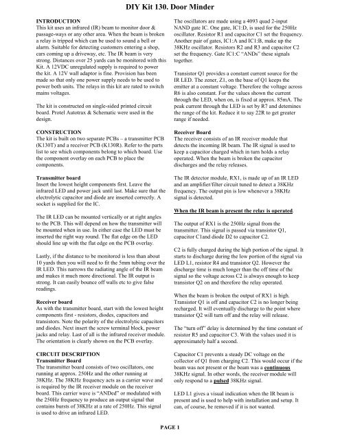
INTRODUCTION<br />
This kit uses an infrared (IR) beam to monitor door &<br />
passage-ways or any other area. When the beam is broken<br />
a relay is tripped which can be used to sound a bell or<br />
alarm. Suitable for detecting customers entering a shop,<br />
cars coming up a driveway, etc. The IR beam is very<br />
strong. Distances over 25 yards can be monitored with this<br />
<strong>Kit</strong>. A 12VDC unregulated supply is required to power<br />
the kit. A 12V wall adaptor is fine. Provision has been<br />
made so that only one power supply needs to be used to<br />
power both units. The relays in this kit are rated to switch<br />
mains voltages.<br />
The kit is constructed on single-sided printed circuit<br />
board. Protel Autotrax & Schematic were used in the<br />
design.<br />
The oscillators are made using a 4093 quad 2-input<br />
NAND gate IC. One gate, IC1:D, is used for the 250Hz<br />
oscillator. Resistor R1 and capacitor C1 set the frequency.<br />
Another pair of gates, IC1:A and IC1:B, make up the<br />
38KHz oscillator. Resistors R2 and R3 and capacitor C2<br />
set the frequency. Gate IC1:C “ANDs” these signals<br />
together.<br />
Transistor Q1 provides a constant current source for the<br />
IR LED. The zener, Z1, on the base of Q1 keeps the<br />
emitter at a constant voltage. Therefore the voltage across<br />
R6 is also constant. For the values shown the current<br />
through the LED, when on, is fixed at approx. 85mA. The<br />
peak current through the LED is set by R7 and detemines<br />
the range of the kit. Reduce it to say 22R to get greater<br />
range if needed.<br />
CONSTRUCTION<br />
The kit is built on two separate PCBs – a transmitter PCB<br />
(K130T) and a receiver PCB (K130R). Refer to the parts<br />
list to see which components belong to which board. Use<br />
the component overlay on each PCB to place the<br />
components.<br />
Transmitter board<br />
Insert the lowest height components first. Leave the<br />
infrared LED and power jack until last. Make sure that the<br />
electrolytic capacitor and diode are inserted correctly. A<br />
socket is supplied for the IC.<br />
The IR LED can be mounted vertically or at right angles<br />
to the PCB. This will depend on how the transmitter will<br />
be mounted when in use. In either case the LED must be<br />
inserted the right way round. The flat edge on the LED<br />
should line up with the flat edge on the PCB overlay.<br />
Lastly, if the distance to be monitored is less than about<br />
10 yards then you will need to fit the 5mm tubing over the<br />
IR LED. This narrows the radiating angle of the IR beam<br />
and makes it much more directional. The IR output is<br />
strong. It can easily bounce off walls etc to give false<br />
readings.<br />
Receiver board<br />
As with the transmitter board, start with the lowest height<br />
components first - resistors, diodes, capacitors and<br />
transistors. Note the polarity of the electrolytic capacitors<br />
and diodes. Next insert the screw terminal block, power<br />
jacks and relay. Last of all is the infrared receiver module.<br />
The orientation is clearly shown on the PCB overlay.<br />
CIRCUIT DESCRIPTION<br />
Transmitter Board<br />
The transmitter board consists of two oscillators, one<br />
running at approx. 250Hz and the other running at<br />
38KHz. The 38KHz frequency acts as a carrier wave and<br />
is required by the IR receiver module on the receiver<br />
board. This carrier wave is “ANDed” or modulated with<br />
the 250Hz frequency to produce an output signal that<br />
contains bursts of 38KHz at a rate of 250Hz. This signal<br />
is used to drive an infrared LED.<br />
Receiver Board<br />
The receiver consists of an IR receiver module that<br />
detects the incoming IR beam. The IR signal is used to<br />
keep a capacitor charged which in turn holds a relay<br />
operated. When the beam is broken the capacitor<br />
discharges and the relay releases.<br />
The IR detector module, RX1, is made up of an IR LED<br />
and an amplifier/filter circuit tuned to detect a 38KHz<br />
frequency. The output pin is low whenever a 38KHz<br />
signal is detected.<br />
When the IR beam is present the relay is operated.<br />
The output of RX1 is the 250Hz signal from the<br />
transmitter. This signal is passed via transistor Q1,<br />
capacitor C1and diode D2 to capacitor C2.<br />
C2 is fully charged during the high portion of the signal. It<br />
starts to discharge during the low portion of the signal via<br />
LED L1, resistor R4 and transistor Q2. However the<br />
discharge time is much longer than the off time of the<br />
signal so the voltage across C2 is always enough to keep<br />
transistor Q2 on and therefore the relay operated.<br />
When the beam is broken the output of RX1 is high.<br />
Transistor Q1 is off and capacitor C2 is no longer being<br />
recharged. It will eventually discharge to the point where<br />
transistor Q2 will turn off and the relay will release.<br />
The “turn off” delay is determined by the time constant of<br />
resistor R5 and capacitor C3. With the values used it is<br />
approximately half a second.<br />
Capacitor C1 prevents a steady DC voltage on the<br />
collector of Q1 from charging C2. This would occur if the<br />
beam was not present or the beam was a continuous<br />
38KHz signal. In other words, the receiver module will<br />
only respond to a pulsed 38KHz signal.<br />
LED L1 gives a visual indication when the IR beam is<br />
present and is used to help with installation and setup. It<br />
can, of course, be removed if it is not wanted.<br />
PAGE 1
<strong>DIY</strong> <strong>Kit</strong> <strong>130.</strong> <strong>Door</strong> <strong>Minder</strong><br />
Zener diode Z1, resistor R6 and capacitor C4 provides a<br />
stable 5.6V supply for the IR module. The relays provided<br />
with this kit are mains rated but use with care. RUDH<br />
110V/10A; RWH 250V/12A, 120VAC/15A.<br />
INSTALLATION<br />
For ease of operation, the transmitter board can be<br />
powered from the receiver board when they are relatively<br />
close together. Two plugs have been supplied for this.<br />
Connecting wire for the length required must be supplied<br />
by you. Otherwise two separate power supplies are<br />
required.<br />
The receiver board contains two DC jacks connected in<br />
parallel. Power from a 12VDC source is connected to one<br />
jack. A lead can then be connected to the other jack and<br />
run to the transmitter board. DC plugs to make up a lead<br />
are supplied with the kit.<br />
Aligning the transmitter and receiver is simply a matter of<br />
pointing the transmitter IR LED at the receiver board and<br />
moving it around until the red LED on the receiver board<br />
lights. This indicates that the beam is being received. The<br />
relay will be operated.<br />
Note:<br />
With power applied the relay is normally operated and<br />
only releases when the beam is broken. The relay contacts<br />
labelled “NO” (Normally Open) and “NC” (Normally<br />
Closed) refer to when the relay is released.<br />
With the relay operated, the “NO” contact will be<br />
connected to the “C” contact and the “NC” contact will be<br />
unconnected.<br />
IF IT DOES NOT WORK<br />
Poor soldering (“dry joints”) is the most common reason<br />
that the circuit does not work. Check all soldered joints<br />
carefully under a good light. Re-solder any that look<br />
suspicious. Check that all components are in their correct<br />
position on the PCB. Are the electrolytic capacitors and<br />
diodes the right way round? Have you fitted the 5mm<br />
tubing over the IR LED on the transmitter board?<br />
Web Address & Email<br />
You can email us at peter@kitsrus.com<br />
See our website at<br />
http://kitsrus.com<br />
This is an improved (natually!) version of the door minder<br />
published in Silicon Chip, april, 1999. It was developed<br />
originally by Oatley Electronics.<br />
PARTS LIST – K130<br />
Transmitter board<br />
Resistors (0.25W carbon)<br />
47 yellow violet black........ R6 ................................. 1<br />
1K brown black red ............ R5 ................................. 1<br />
1K8 brown grey red............ R3 ................................. 1<br />
6K8 blue grey red ............... R2 ................................. 1<br />
47K yellow violet orange.... R1,4 .............................. 2<br />
Capacitors<br />
1nF ceramic 102 ................ C2 ................................. 1<br />
100nF monobloc 104......... C1 ................................. 1<br />
100uF 25V electrolytic ....... C3 ................................. 1<br />
Semiconductors<br />
4.7V 400mW zener diode... Z1.................................. 1<br />
BC557 transistor, PNP........ Q1 ................................. 1<br />
4093 CMOS IC................... IC1................................ 1<br />
Quad 2-input NAND with schmitt trigger inputs<br />
IR LED, EL-1L7................. L1.................................. 1<br />
Miscellaneous<br />
2.5mm DC jack................... X1 ................................. 1<br />
Tubing, 5mm x 25mm long to fit over L1................. 1<br />
PCB, K130T .............................................................. 1<br />
Receiver Board<br />
Resistors (0.25W carbon)<br />
470 yellow violet brown ..... R3,6 .............................. 2<br />
6K8 blue grey red ............... R1,2,4 ........................... 3<br />
47K yellow violet orange.... R5 ................................. 1<br />
Capacitors<br />
10uF 16V electrolytic ......... C1,2,3 ........................... 3<br />
100uF 25V electrolytic ....... C4,5 .............................. 2<br />
Semiconductors<br />
1N4148 signal diode........... D1,2 .............................. 2<br />
1N4004 power diode .......... D3 ................................. 1<br />
5.6V 400mW zener diode... Z1.................................. 1<br />
BC547 transistor, NPN....... Q2 ................................. 1<br />
BC557 transistor, PNP........ Q1 ................................. 1<br />
LED, 5mm red .................... L1.................................. 1<br />
IR receiver module ............. RX1 .............................. 1<br />
PIC-12043S<br />
Miscellaneous<br />
2.5mm DC jack................... X1,2 .............................. 2<br />
Terminal block, 3-way........ X3 ................................. 1<br />
Relay, 12V SPDT ............... RL1............................... 1<br />
“Goodsky” RWH-SH-112D, or RUDH-SS-112D<br />
PCB, K130R.............................................................. 1<br />
Extras<br />
2.5mm DC plugs........................................................ 2<br />
(to make up optional power lead to the transmitter board)<br />
PAGE 2
<strong>DIY</strong> <strong>Kit</strong> <strong>130.</strong> <strong>Door</strong> <strong>Minder</strong><br />
<strong>Door</strong> <strong>Minder</strong> - Receiver Module<br />
<strong>Door</strong> <strong>Minder</strong> - Transmitter Module<br />
PAGE 3
CK1620 - <strong>Door</strong> <strong>Minder</strong><br />
This kit uses an infrared beam to monitor door & passageways<br />
or any other area. When the beam is broken a relay is<br />
tripped which can be used to sound a bell or alarm. Suitable<br />
for detecting customers entering a shop, cars coming up a<br />
driveway, etc. The IR beam is very strong. Distances over 25<br />
yards can be monitored with this <strong>Kit</strong>. A 12VDC supply is<br />
required to power the kit. A 12V wall adaptor is fine.<br />
Provision has been made so that only one power supply<br />
needs to be used to power both units. The relays in this kit<br />
are rated to switch mains voltages.<br />
The kit is constructed on single-sided printed circuit board.<br />
Protel Autotrax for DOS was used in the design.<br />
CONSTRUCTION<br />
The kit is built on two separate PCBs – a transmitter PCB<br />
(K130T) and a receiver PCB (K130R). Refer to the parts list<br />
to see which components belong to which board. Use the<br />
component overlay on each PCB to place the components.<br />
Transmitter board<br />
Insert the lowest height components first. Leave the infrared<br />
LED and power jack until last. Make sure that the electrolytic<br />
capacitor and 4 diodes are inserted correctly. IC sockets are<br />
supplied for the ICs. Note there are two links to add to the<br />
board. One is under an IC.<br />
The IR LED can be mounted vertically or at right angles to<br />
the PCB. This will depend on how the transmitter will be<br />
mounted when in use. In either case the LED must be<br />
inserted the right way round. The flat edge on the LED<br />
should line up with the flat edge on the PCB overlay marked<br />
‘K’.<br />
Lastly, if the distance to be monitored is less than about 10<br />
yards then you will need to fit the 5mm shrink tubing over<br />
the IR LED. This narrows the radiating angle of the IR beam<br />
and makes it much more directional. The IR output is strong.<br />
It can easily bounce off walls etc to give false readings. Note<br />
that the red color shrink tubing is transparent to IR and will<br />
not act as IR shielding. The black tubing is the one to use.<br />
Receiver board<br />
As with the transmitter board, start with the lowest height<br />
components first - resistors, diodes, capacitors and<br />
transistors. Note the polarity of the electrolytic capacitors and<br />
diodes. Next insert the screw terminal block, power jacks and<br />
relay. Last of all is the infrared receiver module. The<br />
orientation is clearly shown on the PCB overlay: : the<br />
detecting lens bump faces outwards. Power must be center<br />
positive. A protection diode D4 is there to protect the circuit<br />
if the wrong polarity is plugged in.<br />
CIRCUIT DESCRIPTION - Transmitter Board<br />
The transmitter board consists of two square-wave<br />
oscillators, one running at approx. 250Hz and the other<br />
running at 38kHz. The 38kHz frequency acts as a carrier<br />
wave and is required by the IR receiver module on the<br />
receiver board. This carrier wave is “ANDed” or modulated<br />
by the 250Hz frequency to produce an output signal that<br />
contains bursts of 38kHz at a rate of 250Hz. This signal is<br />
used to drive an infrared LED. The oscillators are made by<br />
PAGE 1<br />
using two 555 timer ICs set up as “astable” (free running)<br />
multivibrators. IC1 is used for the 250Hz oscillator. Resistor<br />
R1 and R2 and capacitor C1 set the frequency. Another 555<br />
chip, IC2, is used for the 38KHz oscillator. Resistors R4 and<br />
R5 and capacitor C3 set the frequency.<br />
Notice the diodes D1 and D3. These are provided to create a<br />
“symmetrical” output. Normally the external capacitor C1<br />
(C3) charges through resistors R1 and R2 (R4 and R5) and<br />
discharges through R2 (R5). Without the diodes this output<br />
waveform would have a longer “high” time than the “low”<br />
time. The diode bypasses resistor R2 (and R5) when the<br />
capacitor is charging, so that it is only charged via R1 (or<br />
R5). This gives the same charging and discharging time and<br />
so the output waveform has equal high and low times.<br />
The charge time (output high) is given by:<br />
T HIGH = 0.693 x R1 x C1 (or 0.693 x R4 x C3)<br />
The discharge time (output low) is given by:<br />
T LOW = 0.693 x R2 x C1 (or 0.693 x R5 x C3)<br />
The output frequency = 1 / (T HIGH + T LOW )<br />
For an excellent website describing all this and more go to<br />
http://www.uoguelph.ca/~antoon/gadgets/555/555.html<br />
For an animation of the 555 as an astable multivibrator see<br />
http://www.williamson-labs.com/480_555.htm<br />
The output from the IC1 is coupled via diode D2 and resistor<br />
R3 to the ‘trigger’ input of IC2. When the IC1 output is low<br />
it stops IC2 from running and IC2’s output is forced high (no<br />
IR LED current). When IC1 output is high, IC2 runs and the<br />
IR LED is pulsed at 38KHz.<br />
The Waitrony IR LED is driven directly from the output of<br />
IC2. Resistor R6 sets the maximum LED current. With a<br />
12VDC supply the current is about 45mA (the LED drops 2V<br />
across it when conducting). Lowering the value of R6 will<br />
increase the current through the LED thus boosting the signal<br />
strength. This may be necessary if the kit is used outside in<br />
direct sunlight or if you need “very long range”. Keep in<br />
mind that the maximum current that the 555 can handle is<br />
200mA. See the IR LED data sheet at<br />
http://kitsrus.com/pdf/ie-0530hp.pdf<br />
Receiver Board<br />
The receiver consists of an IR receiver module that detects<br />
the incoming IR beam from the transmitter. The IR signal is<br />
used to keep a capacitor charged which in turn holds a relay<br />
operated. When the beam is broken the capacitor discharges<br />
and the relay releases.<br />
A Kodenshi IR receiver/detector module, RX1, is made up of<br />
an an amplifier/filter circuit tuned to detect a 38kHz<br />
frequency. The output pin is low whenever a 38kHz signal is<br />
detected.
When the IR beam is present the relay is operated.<br />
A cheaper IR module from Waitrony we found did not hold<br />
the output signal when the beam was permanently<br />
interrupted.<br />
The output of RX1 is the 250Hz signal from the transmitter.<br />
This signal is passed via transistor Q1, capacitor C1and diode<br />
D2 to capacitor C2. C2 is fully charged during the high<br />
portion of the signal. It starts to discharge during the low<br />
portion of the signal via LED L1, resistor R4 and transistor<br />
Q2. However the discharge time is much longer than the off<br />
time of the signal so the voltage across C2 is always enough<br />
to keep transistor Q2 on and therefore the relay operated.<br />
When the beam is broken the output of RX1 is high.<br />
Transistor Q1 is off and capacitor C2 is no longer being<br />
recharged. It will eventually discharge to the point where<br />
transistor Q2 will turn off and the relay will release. The<br />
“turn off” delay is determined by the time constant of resistor<br />
R5 and capacitor C3. With the values used it is approx. half a<br />
second.<br />
Capacitor C1 prevents a steady DC voltage on the collector<br />
of Q1 from charging C2. This would occur if the beam was<br />
not present or the beam was a continuous 38kHz signal. In<br />
other words, the receiver module will only respond to a<br />
pulsed 38kHz signal.<br />
LED L1 gives a visual indication when the IR beam is<br />
present and is used to help with installation and setup. Zener<br />
diode Z1, resistor R6 and capacitor C4 provides a stable 5.6V<br />
supply for the IR module. The Goodsky RWH relays are<br />
mains rated: 250V/12A; 120VAC/15A.<br />
INSTALLATION<br />
For ease of operation, the transmitter board can be powered<br />
from the receiver board when they are relatively close<br />
together. Two extra DC plugs have been supplied for this.<br />
Connecting wire for the length required must be supplied by<br />
you. Otherwise two separate power supplies are required.<br />
The receiver board contains two DC jacks connected in<br />
parallel. Power from a 12VDC source is connected to one<br />
jack. A lead can then be connected to the other jack and run<br />
to the transmitter board.<br />
Aligning the transmitter and receiver is a matter of pointing<br />
the transmitter IR LED at the receiver board and moving it<br />
around until the red LED on the receiver board lights and the<br />
relay clicks on. This indicates that the beam is being<br />
received.<br />
Note:<br />
With power applied the relay is normally operated and only<br />
releases when the beam is broken. The relay contacts labelled<br />
“NO” (Normally Open) and “NC” (Normally Closed) refer to<br />
when the relay is released. With the relay operated, the “NO”<br />
<strong>DIY</strong> <strong>Kit</strong> <strong>130.</strong> <strong>Door</strong> <strong>Minder</strong><br />
contact will be connected to the “C” contact and the “NC”<br />
contact will be unconnected.<br />
IF IT DOES NOT WORK<br />
Poor soldering (“dry joints”) is the most common reason that<br />
the circuit does not work. Check all soldered joints carefully<br />
under a good light. Re-solder any that look suspicious. Check<br />
that all components are in their correct position on the PCB.<br />
Are the electrolytic capacitors & diodes around the right way<br />
round? Have you fitted the 5mm tubing to the IR LED on the<br />
transmitter board? This is an improved (naturally) version of<br />
the door minder published in Silicon Chip, april, 1999. It was<br />
developed originally by Oatley Electronics, Sydney. New<br />
version of this kit released December, 2001. The transmitter<br />
board has been completely revised.<br />
Web Address<br />
Website: www.electronickits.com<br />
PARTS LIST – K130<br />
Transmitter board<br />
Resistors (0.25W 5%, carbon)<br />
220R................................... R6..................................1<br />
1K....................................... R3..................................1<br />
2K2..................................... R4,5...............................2<br />
2K7..................................... R1,2...............................2<br />
Capacitors<br />
10nF ceramic...................... C2,3,4............................3<br />
1uF electrolytic mini .......... C1..................................1<br />
1N4148 signal diode ......... D1,2,3............................3<br />
1N4004 power diode.......... D4..................................1<br />
LM/NE555 Timer IC......... IC1,2..............................2<br />
IR LED............................... L1 ..................................1<br />
2.5mm DC jack .................. X1..................................1<br />
IC sockets, 8 pin................. for IC1,2........................2<br />
Tubing, BLACK, 5mm x 25mm long ........................1<br />
(fitted over L1)<br />
PCB, K130TV2..........................................................1<br />
Receiver Board<br />
Resistors (0.25W 5%, carbon)<br />
470R................................... R3,6...............................2<br />
6K8..................................... R1,2,4............................3<br />
47K..................................... R5..................................1<br />
10uF 25V electrolytic......... C1,2,3............................3<br />
100uF 16V electrolytic....... C4,5...............................2<br />
1N4148 signal diode .......... D1,2...............................2<br />
1N4004 power diode.......... D3, 4..............................2<br />
5.6V 400mW zener diode .. Z1 ..................................1<br />
BC547 transistor, NPN....... Q2..................................1<br />
BC557 transistor, PNP Q1 (might be marked Q3 on the<br />
PCB)................................... .......................................1<br />
LED, 5mm red.................... L1 ..................................1<br />
IR receiver module............. RX1 ...............................1<br />
2.5mm DC jack .................. X1,2...............................4<br />
Terminal block, 3-way ....... X3..................................1<br />
Relay, 12V SPDT............... RL1................................1<br />
“Goodsky” RWH-SH-112D<br />
PCB, K130R...............................................................1<br />
PAGE 2
CK1620 - <strong>Door</strong> <strong>Minder</strong><br />
<strong>Door</strong> <strong>Minder</strong> - Receiver Module<br />
<strong>Door</strong> <strong>Minder</strong> - Transmitter Module<br />
PAGE 3