Diagram 2 - TwinHeat
Diagram 2 - TwinHeat
Diagram 2 - TwinHeat

You also want an ePaper? Increase the reach of your titles
YUMPU automatically turns print PDFs into web optimized ePapers that Google loves.
MANUAL FOR INSTALLATION<br />
ME20i ME40i ME80i<br />
Version 1.3 – May 2011<br />
This manual should be read carefully before the installation commences!<br />
How to assemble the plant .............................................................................page 2<br />
Connection to the heating system ..................................................................page 3<br />
Connection of the sprinkler.............................................................................page 4<br />
Connection of the safety heat exchanger .......................................................page 5<br />
(Only for boilers provided with safety heat exchanger)<br />
Connection to the chimney.............................................................................page 5<br />
Connection of the external auger ...................................................................page 6<br />
Connection to the electrical net ......................................................................page 6<br />
<strong>Diagram</strong> 1 – How to fit the water cooled burner tube, (side) ..........................page 7<br />
<strong>Diagram</strong> 1.1 – How to fit the water cooled burner tube, (rear)........................page 8<br />
<strong>Diagram</strong> 2 – Connection to the heating system..............................................page 9<br />
<strong>Diagram</strong> 3 – Connection to the chimney ......................................................page 10<br />
<strong>Diagram</strong> 4 – Connection of the external auger.............................................page 11<br />
<strong>Diagram</strong> 5 – Electrical diagram 400V – 3 phase ..........................................page 12<br />
<strong>Diagram</strong> 5.1 – Electrical diagram 230V – 1 phase .......................................page 13<br />
<strong>Diagram</strong> 6 – Electrical diagram, start-stop signal for external auger ...........page 14<br />
Starting up the boiler – See users manual section 2<br />
Nørrevangen 7 DK-9631 Gedsted Phone +45 98645222 Fax. +45 98645244<br />
Mail: twinheat@twinheat.dk Web: www.twinheat.dk
2<br />
The installation of this plant must be made in accordance with the local rules<br />
and regulations on the place of installation<br />
Before the plant is placed on its final place it should be inspected carefully for<br />
transport damages. Possible damages should be reported to the forwarder.<br />
How to assemble the plant<br />
The plant is delivered on 2 Euro pallets and consists of a boiler, a stoker and a<br />
burner tube which must be assembled before installation.<br />
1. The water cooled burner tube is fixed on the stoker unit by means of bolts<br />
included. The gasket plus bolts for the fixation are included.<br />
2. The stoker unit with the now fitted burner tube is pushed into the pre made<br />
hole with flange in the boiler.<br />
3. Before you fixate the stoker and burner tube to the boiler (with 2 bolts) you<br />
must adjust the height of the stoker by means of 2 adjustment screws on the<br />
leg, that it is placed horizontal and in a 90 º angle to the boiler. It is<br />
absolutely important, that the water cooled burner tube is horizontals as you<br />
otherwise might experience air pockets in the system.<br />
4. The water cooling of the burner tube can now be installed as shown on<br />
diagram 1 and diagram 1.1 All parts included fittings and circulation pump<br />
are in the accessories box included. (Please note, that the circulation pump<br />
is for circulation between boiler and burner tube only)<br />
5. The combustion fan is fitted on the square stud of the burner tube, no gasket<br />
needed.<br />
6. The hose for pressure equalising in the stoker is fitted on the stud on the<br />
burner tube<br />
7. The draft regulator, needed by manual heating, is fixed on the top of the<br />
boiler in the same side as the door hinges for the combustion room door.<br />
The chain is connected to the lower air inlet on the boiler.<br />
8. The plug for power to the boiler is pushed in and secured by a screw. The<br />
cable is placed in the tray underneath the plug. Cable W7 is for circulation<br />
pump.<br />
INSTALLATION
3<br />
The sketch indicates the recommended minimum distances in the boiler room.<br />
According to Danish fire rules the room must be equipped with a ½ to ¾ inch high<br />
pressure water tap and a ventilation opening, either as a window or as a ventilation grill<br />
B<br />
A<br />
B<br />
A<br />
D<br />
C<br />
C<br />
Recommended minimum distances in the boiler room<br />
(the stoker is placed at the right ore left side of the boiler)<br />
Recommended minimum distances in the boiler room<br />
(the stoker is placed at the rear side of the boiler)<br />
Measures in cm<br />
ME 20i<br />
ME 40i<br />
ME 80i<br />
A<br />
B<br />
7 20 120<br />
10 20<br />
10 20<br />
C<br />
160<br />
Measures in cm<br />
ME 20i<br />
ME 40i<br />
12 20 120<br />
160<br />
160 ME 80i 10 20 160<br />
A<br />
12<br />
B<br />
20<br />
C<br />
D<br />
80<br />
80<br />
80<br />
Connection to the heating system<br />
See diagram 2<br />
The boiler must be connected as shown in diagram 2 or as demanded by local<br />
statutes.<br />
Further information is in the manual, section. 7<br />
The minimum amount of water passing through the boiler must be (see table)<br />
Plant type<br />
Nom. effect Min. Amount of<br />
[kW] water [m³/h]<br />
ME 20i 29 2,5<br />
ME 40i 48 4,1<br />
ME 80i 80 6,9<br />
Water returning to the boiler must always be min. 60°C<br />
If the above is not adhered to you will risk increased tear of the steel in the<br />
boiler, resulting in a shorter life expectation for the plant.<br />
INSTALLATION
4<br />
According to Danish laws and regulations this boiler must be connected to a<br />
system with “open” expansion tank. Please check you local regulations<br />
General<br />
The expansion tank must be able to contain at least 4 % of the total amount of<br />
water in the heating system. Should the plant be installed with an accumulation<br />
tank, then the expansion tank must be able to contain at least 8 % of the total<br />
amount of water in the heating system.<br />
The boiler must be in non blockage connection to the expansion tank (You must<br />
not be able to block the pipe between)<br />
Should the open expansion tank be placed in a not frost safe place, that tank<br />
itself must be protected against frost. The circulation to the tank may be<br />
controlled by a thermostatic valve or similar in order to secure, that the boiler<br />
water is getting minimum access to oxygen.<br />
Connection of the sprinkler<br />
The sprinkler system for the boiler must be under constant water pressure from<br />
a ½ inch tap with a safety faucet and be connected to the dirt collector under<br />
the pressure tank.<br />
Please make sure, that pipes / hoses are free of dirt or metal shavings.<br />
You must test the system, when it has come under pressure.<br />
The easiest way to test the sprinkler system is to unscrew the hose from the<br />
thermostatic valve to the auger channel. Then press the red cap under the valve<br />
to activate it<br />
After testing the sprinkler system it is important to check that the valve is closing<br />
properly! (Dirt ore the like, in the valve seat, can prevent this)<br />
INSTALLATION
5<br />
Connection of the safety heat exchanger (Quenching coil)<br />
(Only for boilers provided with safety heat exchanger)<br />
The boiler has a build-in safety<br />
heat exchanger which cools the<br />
boiler in case of pump failure or<br />
the like. The system will be<br />
activated if the water<br />
temperature in the boiler<br />
exceeds 95°C.<br />
Drain from quenching coil<br />
Supply cold water for<br />
quenching coil<br />
Thermal safety valve - 95°C<br />
Temperature sensor<br />
for thermal safety valve<br />
The thermal safety valve must<br />
be connected to constant water<br />
pressure from a G¾”/22mm<br />
pipe. The water pressure must<br />
be minimum 2 bar and the<br />
temperature maximum 15°C<br />
There must be no shutoff valves<br />
on the pipe supplying the valve.<br />
Flush the pipes before<br />
connecting to the thermal safety<br />
valve. Dirt or metal shavings<br />
can cause the valve to<br />
malfunction.<br />
The return drain from the safety heat exchanger G¾” must be connected to a<br />
drain.<br />
The pipe used to connect to the drain must have a sufficient size to avoid the<br />
emergence of backpressure.<br />
After installation the system must be tested to ensure free passage trough the<br />
safety heat exchanger. The thermal safety valve can be manually activated by<br />
pressing the red cap.<br />
Connection to the chimney<br />
See diagram 3<br />
Further information is in the user manual, section. 7<br />
In order to get a good heating economy and to avoid smoke problems you must<br />
connect the boiler to a suitable chimney. The boiler should be placed as close<br />
to the chimney as possible.<br />
Should the chimney be too unsuitable or under difficult draft conditions you<br />
might have to install a flue fan.<br />
It is in general recommended to install a draft stabilizer (See diagram 3)<br />
A chimney with unstable draft can case unstable running conditions of the plant.<br />
INSTALLATION
6<br />
It is important that the flue pipe is insulated with a 30mm fire resistant<br />
mat, to avoid that the flue gasses are condensing in it.<br />
Recommended chimney dimensions.<br />
Plant<br />
type<br />
Max. effect,<br />
input<br />
Flue outlet on<br />
boiler<br />
Free opening in<br />
chimney<br />
Height of<br />
chimney<br />
M20i 34 kW. Ø 155 mm Ø 160-180 mm 5-6 metre<br />
M40i 55 kW. Ø 187 mm Ø 180-200 mm 5-8 metre<br />
M80i 92 kW. Ø 215 mm Ø 200-250 mm 6-8 metre<br />
Connection of the external auger<br />
See diagram no 4<br />
The connection must be made with a flexible hose. The auger must not support<br />
on the stoker unit and vibrations from the auger must not be transmitted to the<br />
stoker unit.<br />
In case the plant is connected to a silo placed at the loft above you should also<br />
use a flexible hose, which must be emptied after each filling. The hole through<br />
the ceiling must be made fire-proof.<br />
Connection to the electrical net<br />
See diagram no 5 / 5.1<br />
The boiler can be built for either 400V 3 phase or 230V single phase<br />
connection.<br />
Check boiler data plate for electrical connection.<br />
In Denmark the installation must be made by an authorised electrician. Here too<br />
we ask you to check your local regulations<br />
Electrical supply for the stoker plant:<br />
There should be specific switch for this plant only<br />
Electrical supply for the internal circulation pump:<br />
The internal circulation pump (placed under the burner tube) is to be connected<br />
to cable no. W7<br />
The pump must not be started before filled with water, as this might damage it.<br />
Setting of the internal circulation pump:<br />
The pump must be set to run in a fixed step. It must not run in Auto mode!<br />
Boiler<br />
ME20i<br />
ME40i<br />
ME80i<br />
Pump step<br />
I<br />
I<br />
II<br />
Connection of start – stop signal for external auger:<br />
See diagram no 6<br />
The motor protection relay (contact) for the external auger must be supplied<br />
with a start – stop signal from the controlling unit of the plant, which is placed in<br />
a plastic box at the side of the fuel valve, on the rear of the stoker.<br />
INSTALLATION
7<br />
<strong>Diagram</strong> 1 - How to fit the water cooled burner tube by<br />
plants with stoker placed at the side of the boiler<br />
Draft regulator<br />
Supply boiler<br />
(No gasket)<br />
Connection for sprinkler<br />
Hose for pressure<br />
equalising pipe<br />
Stoker unit<br />
Boiler<br />
Burner tube<br />
Included fittings<br />
2 pcs. 3/4" Hose<br />
1 pcs. 3/4" Safety valve<br />
2 pcs. 3/4" Shutoff valve<br />
1 pcs. 1/2" Shutoff valve<br />
1 pcs. Cirkulation pump<br />
5 pcs 3/4" Hexagon nipple<br />
1 pcs. 3/4"x 3/4"x 1/2" Tee<br />
1 pcs. 1"x 3/4" Hexagon nipple<br />
1 pcs. 3/4" Tee<br />
2 pcs. 3/4" Elbow<br />
2 pcs. 3/4" Union joint, for pump<br />
Elbows and valves are to<br />
be placed horizontal, to<br />
avoid airpockets in the<br />
hoses!<br />
By M40 is included a 3/4" connection sleeve !<br />
DIAGRAM 1
8<br />
<strong>Diagram</strong> 1.1 - How to fit the water cooled burner tube by<br />
plants with stoker placed at the rear end of the boiler<br />
Draft regulator<br />
Supply boiler<br />
(No gasket)<br />
Connection for sprinkler<br />
Hose for pressure<br />
equalising pipe<br />
Boiler<br />
Stoker unit<br />
Burner tube<br />
Included fittings<br />
2 pcs. ¾" hose<br />
1 pcs. ¾" safety valve<br />
1 pcs. cirkulation pump<br />
2 pcs. ¾" union joint, for pump<br />
2 pcs. ¾" shutoff valve<br />
1 pcs. ½" shutoff valve<br />
5 pcs. ¾" hexagon nipple<br />
1 pcs. ¾" tee<br />
1 pcs. ¾" x ¾" x ½" tee<br />
1 pcs. ¾" plug<br />
ME20: ¾" x 1" hexagon nipple<br />
ME40: ¾" x 1½" hexagon nipple<br />
ME80: ¾" x 2" connection nipple + ¾" hexagon nipple<br />
DIAGRAM 1.1
9<br />
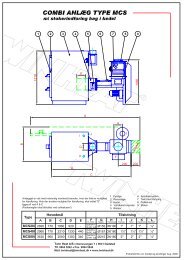
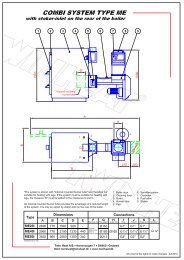
<strong>Diagram</strong> 2 – Connection to the heating system<br />
Open expansion vessel<br />
shutoff valve<br />
3 way thermostat<br />
controlled mixing valve<br />
(shunt valve)<br />
Manuel regulation valve<br />
(return valve)<br />
EÅ<br />
V1-V2<br />
V3<br />
V4<br />
shutoff valves on supply and return, in the boiler<br />
room. More can be installed if needed.<br />
Boiler shunt valve secure that the return water to the<br />
boiler always is over 60°C.<br />
To protect open expansion vessel against frost<br />
Can be thermostatic return valve<br />
Airing V5 Airing, possible automatic, placed where needed.<br />
Thermometer<br />
T1-T4<br />
Thermometer for supply, water return before and<br />
after shunt valve and for flue temperature<br />
Temperature sensor TF1 Temperature sensor to regulate shunt valve.<br />
Manometer M1 Manometer for boiler pressure.<br />
Pump P1 Circulation pump for heating system<br />
DIAGRAM 2
10<br />
<strong>Diagram</strong> 3 – Connection to the chimney<br />
* Prefabricated module chimneys should not be placed on top of the flue<br />
outlet, as this allows rainwater or possible condense water to run directly<br />
down into the heat exchanger of the boiler, where it will cause corrosion !<br />
Brick-build or block-build chimney<br />
Brick-build or block-build chimney<br />
Insulation<br />
Elbow with clean out hole<br />
Draft stabilizer mounted<br />
in chimney<br />
Clean out<br />
Draft stabilizer mounted<br />
on flue pipe<br />
Clean out<br />
*Module chimney with steel or ceramic liners<br />
Insulated tee module with<br />
draft stabilizer<br />
Insulated tee module with<br />
clean out<br />
Wall support<br />
*Module chimney with steel or ceramic liners<br />
Insulation<br />
Insulated tee module with<br />
clean out<br />
Elbow with clean out hole<br />
Draft stabilizer mounted<br />
on flue pipe<br />
Wall support<br />
DIAGRAM 3
11<br />
<strong>Diagram</strong> 4 – Connection of the external auger<br />
Fuel from silo placed at<br />
the loft above<br />
Flexible hose<br />
Fuel valve<br />
Automatic fire damper<br />
closes incase of fire in the<br />
boiler room<br />
Fuel from external silo<br />
Flexible hose<br />
Fuel valve<br />
The auger must not support on the stoker unit and<br />
vibrations from the auger must not be transmitted to<br />
the stoker unit.<br />
DIAGRAM 4
5<br />
12<br />
<strong>Diagram</strong> 5 – Electrical diagram 400V – 3 phase<br />
X3<br />
Contaktor Safety<br />
14<br />
15<br />
16<br />
17<br />
22<br />
23<br />
24<br />
18<br />
19<br />
20<br />
21<br />
X11<br />
4<br />
5<br />
6<br />
7<br />
8<br />
9<br />
10<br />
11<br />
12<br />
13<br />
X6<br />
X5<br />
1<br />
2<br />
3<br />
33<br />
34<br />
35<br />
36<br />
37<br />
38<br />
39<br />
40<br />
X2<br />
White<br />
White<br />
O2 +Signal<br />
OV Signal<br />
0V AC<br />
12V AC<br />
N2<br />
U2<br />
U<br />
Power Supply<br />
3 x 400V AC 50Hz<br />
+ N + PE<br />
X1<br />
Blower<br />
mot or<br />
Stoker<br />
mot or<br />
X7<br />
Condensator<br />
V1<br />
U1<br />
W1<br />
W<br />
V<br />
N<br />
M<br />
X8<br />
Relay Silo auger<br />
Relay Belimo mot or<br />
24V AC<br />
L1 L2 L3<br />
T1 T2 T3<br />
lysrød<br />
24VAC<br />
rød<br />
U1 V1<br />
W1 N<br />
SP3<br />
U3 N<br />
SP4<br />
L1<br />
N<br />
brown<br />
blue<br />
grey<br />
black<br />
Yel/green<br />
blue<br />
black<br />
black<br />
black<br />
JP3<br />
F1 4AT<br />
F2<br />
4AT<br />
12VAC<br />
orange<br />
F3<br />
315mAT<br />
0V<br />
white<br />
N W5<br />
F4<br />
315mAT<br />
U V W N<br />
U3<br />
N<br />
A1<br />
A2<br />
1 2 3 4 5 6 7<br />
1 2 3 4 5<br />
6 7<br />
A1<br />
A1<br />
A2<br />
A2<br />
14<br />
11<br />
14<br />
11<br />
10 11 4 5 8 N V1<br />
6 7<br />
M<br />
9 8<br />
N<br />
L1<br />
Cirkulat ion<br />
pump<br />
Burner tube<br />
7<br />
M<br />
Transformer<br />
Silo-auger<br />
12VDC<br />
0VDC<br />
12VAC<br />
0VAC<br />
24VAC<br />
0VAC<br />
12VDC<br />
Capacitive<br />
sensor<br />
12VDC<br />
Contakt<br />
Belimo<br />
0VAC<br />
12VAC<br />
AC-1<br />
9<br />
8<br />
2 1 3<br />
SP2<br />
SP1<br />
SP5<br />
4 5<br />
6 7<br />
9 8<br />
SP6 SP7<br />
SP8<br />
X9<br />
SP9<br />
SP10<br />
Brown<br />
White<br />
Blue<br />
AC-GND<br />
X4<br />
7 8 5 6<br />
7 8 5 6<br />
Black<br />
Grey<br />
Lid Safety-Switch<br />
Hot boiler thermostat<br />
25<br />
26<br />
27<br />
28<br />
29<br />
30<br />
31<br />
32<br />
41<br />
42<br />
43<br />
44<br />
45<br />
46<br />
Lambda<br />
probe<br />
X10<br />
1 2 1 2 3 4<br />
Boiler temp sensor<br />
1 2 3 4<br />
NTC<br />
12VDC<br />
12VDC<br />
Belimo motor<br />
TH2006 O2 Controller<br />
Electrical diagram 400V AC 3 phases<br />
28-01-10 MM<br />
4 3 2 1<br />
1 3<br />
L1<br />
2 10<br />
N<br />
Foto-sensor<br />
1<br />
1<br />
2<br />
2<br />
Red<br />
Yellow<br />
M<br />
Transmitter<br />
2 1<br />
6<br />
8<br />
Reciever<br />
Capacitive<br />
sensor<br />
DIAGRAM 5
13<br />
<strong>Diagram</strong> 5.1 – Electrical diagram 230V – 1 phase<br />
DIAGRAM 5.1
14<br />
<strong>Diagram</strong> 6 – Electrical diagram, Start – stop signal for<br />
external auger<br />
DIAGRAM 6