
Create successful ePaper yourself
Turn your PDF publications into a flip-book with our unique Google optimized e-Paper software.
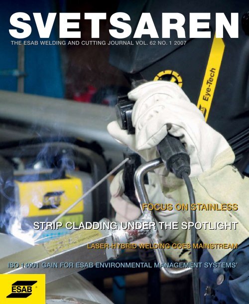
THE ESAB WELDING AND CUTTING JOURNAL VOL. 62 NO. 1 <strong>2007</strong><br />
FOCUS ON STAINLESS<br />
STRIP CLADDING UNDER THE SPOTLIGHT<br />
LASER-HYBRID WELDING GOES MAINSTREAM<br />
ISO 14001 GAIN FOR ESAB ENVIRONMENTAL MANAGEMENT SYSTEMS’
<strong>Svetsaren</strong><br />
Towards a bright and<br />
shiny future - together<br />
Articles in <strong>Svetsaren</strong> may be reproduced<br />
without permission, but with an<br />
acknowledgement to ESAB.<br />
Publisher<br />
Johan Elvander<br />
Editor<br />
Ben Altemühl<br />
Editorial committee<br />
Tony Anderson, Klaus Blome, Carl Bandhauer,<br />
Christophe Gregoir, Lars-Erik Stridh, Johnny<br />
Sundin, Björn Torstensson.<br />
Address<br />
<strong>Svetsaren</strong><br />
ESAB AB Central Market Communications<br />
Box 8004<br />
S-402 77 Gothenburg<br />
Sweden<br />
Internet address<br />
http://www.esab.com<br />
E-mail: svetsaren@esab.com<br />
Printed in The Netherlands by True Colours<br />
Dear reader,<br />
Stainless steels are fascinating, versatile materials that<br />
affect our lives in more ways than most of us are<br />
aware of. Stainless steels are found in environments<br />
such as high to very low temperature applications,<br />
food and beverage processing, oil, gas and chemicals<br />
industries, transportation and architecture. As a group,<br />
they outperform all other construction materials in<br />
terms of growth - a steady increase of some 5% per<br />
year. With greater focus on low long-term maintenance<br />
costs, increasing environmental awareness and<br />
concerns about life-cycle costs, the demand for<br />
stainless steel can only continue to grow.<br />
LEIF KARLSSON<br />
Although consumable manufacturers, naturally, follow the lead of steel makers in<br />
formulating new alloys, weldability remains an important aspect in stainless steel<br />
development. Potential applications for new grades steel are reduced if welding is a<br />
problem, or if suitable welding consumables are not available. ESAB has a long history in<br />
stainless steel welding - stainless stick electrodes were early included in the<br />
consumables range. In fact, the first issue of <strong>Svetsaren</strong>, in 1936, reported on an<br />
application using the stainless electrode ESAB OK R3 (18%Cr 10.5%Ni 1.5%Mo).<br />
Stainless steel consumables development is still a priority for ESAB. Combining modern<br />
consumables with today’s advances in mechanisation, software controlled power sources<br />
and new welding methods, such as laser-hybrid welding, brings more opportunities to<br />
produce high quality, high productivity welds than ever before.<br />
More than one issue of <strong>Svetsaren</strong> would be needed to give more than just a glimpse of<br />
the fascinating world of stainless steel welding. However, we hope that this issue of<br />
<strong>Svetsaren</strong> gives you a flavour of ESABs developments by highlighting environments and<br />
applications where our consumables and equipment are used.<br />
THE ESAB WELDING AND CUTTING JOURNAL VOL. 62 NO. 1 <strong>2007</strong><br />
FOCUS ON STAINLESS<br />
STRIP CLADDING UNDER THE SPOTLIGHT<br />
LASER-HYBRID WELDING GOES MAINSTREAM<br />
MMA welding of<br />
thin stainless pipes<br />
in the paper and<br />
pulp industry.<br />
And, finally, ESAB will continue to actively contribute to the bright future of stainless<br />
steels – and we invite all our customers to join us!<br />
LEIF KARLSSON<br />
SENIOR EXPERT & MANAGER RESEARCH PROJECTS.<br />
ISO 14001 GAIN FOR ESAB ENVIRONMENTAL MANAGEMENT SYSTEMS’
4 - <strong>Svetsaren</strong> no. 1 - <strong>2007</strong>
Contents<br />
07<br />
09<br />
10<br />
16<br />
23<br />
27<br />
28<br />
ESAB ISO 14001 certified worldwide<br />
ISO 14001 is the international standard<br />
for environmental management systems.<br />
ESAB opens its first welding consumables<br />
factory in China<br />
New factory part of ESAB’s goal to<br />
strengthen position in Asia.<br />
Disbonding of Austenitic Weld Overlays<br />
in Hydroprocessing Applications<br />
Mechanisms, testing and factors influencing<br />
the risk of disbonding, focussing<br />
on welding related aspects.<br />
Practical applications of ESAB strip<br />
cladding technology<br />
This article discusses two strip cladding<br />
methods and describes applications at<br />
two major Italian fabricators.<br />
Providing fresh water to The Middle East<br />
ESAB provides a full range of welding<br />
consumables for the many, often exotic,<br />
materials in desalination plants.<br />
ESAB top specialist Dr Leif Karlsson wins<br />
TWI Brooker Medal<br />
Medal presented in recognition of contribution<br />
to the science, technology and<br />
industrial exploitation of metal joining.<br />
Aristo TM robot package appreciated at<br />
Siemens Magnet Technology<br />
Aristo TM inverter technology provides<br />
advanced programming and process<br />
functions, including ESAB SuperPulse.<br />
32<br />
35<br />
38<br />
42<br />
47<br />
ESAB MMA electrodes for positional<br />
welding of thin stainless pipe and sheet<br />
ESAB introduces three new rutile MMA<br />
electrodes with excellent all-positions arc<br />
control at very low welding currents.<br />
Welding of 13% Cr-steels using the<br />
laser-hybrid process<br />
An ESAB Process Centre report on<br />
welding to bus chassis parts in<br />
supermartensitic stainless steel.<br />
Making barrels with drums<br />
ESAB matte stainless steel MIG wire from<br />
Mini Marathon Pac delivers dependability<br />
in stainless steel beer barrel production.<br />
Gas-shielded arc welding of duplex steels<br />
The welding of duplex stainless steels<br />
with detailed advice on MIG and TIG<br />
shielding gas selection.<br />
Product News<br />
• MechTig C2002i power sources<br />
for mechanised TIG welding.<br />
• AristoFeed wire feeders for<br />
Aristo TM power sources.<br />
• OrigoArc 4000i/5000i heavy duty<br />
MMA power sources.<br />
• OrigoMig 320 step-switched<br />
MIG/MAG power source.<br />
• New TXH TIG torches.<br />
• OrigoTig 3000i meets most<br />
TIG welding needs.<br />
• New strip cladding heads.<br />
• New ESAB web sites go live.<br />
• OrigoMig 410/510 step-switched<br />
MIG/MAG power source.
6 - <strong>Svetsaren</strong> no. 1 - <strong>2007</strong>
ESAB Environmental Management<br />
System - ISO 14001 certified worldwide<br />
Unique in the welding and cutting industry.<br />
STEFAN LARSSON, ESAB AB, GOTHENBURG SWEDEN<br />
ISO 14001 is the international<br />
standard for environmental<br />
management systems (EMS),<br />
providing organizations with a<br />
framework for achieving their<br />
environmental and economic goals.<br />
conversion to<br />
raw materials<br />
or components<br />
ESAB is one of the very few international companies<br />
to have acquired a global ISO 14001 certification,<br />
covering everything from design, development and<br />
production to sales and service worldwide.<br />
Customers are assured that every ESAB product is<br />
produced to the same environmental standard with<br />
every step taken to minimize environmental impact.<br />
Customers striving to obtain ISO 14001 certification<br />
themselves, or just aiming to continually improve<br />
their environmental performance, will be able to<br />
benefit from having ESAB as a dedicated partner.<br />
Reducing environmental impact<br />
The fundamental reason for implementing an<br />
environmental management system (EMS) worldwide<br />
is to have a structured approach towards<br />
minimizing the negative impact of our activities on<br />
the environment. Responsibility extends far beyond<br />
the office doors and factory gates of ESAB, so it is<br />
important to understand the impact of our activities<br />
in a broader sense. By using a lifecycle approach,<br />
we can map the effects of a product from designer’s<br />
desk to the end of its life and including disposal.<br />
Right from the early stages of development, aspects<br />
such as finding alternatives for hazardous<br />
components, or energy consumption during<br />
production and use, and packaging waste and<br />
recyclability are all taken into account. This results in<br />
products with a reduced environmental impact.<br />
• OK AristoRod – copper-free welding wire<br />
Advanced surface technology applied in the<br />
manufacturing of ESAB MAG welding wires has<br />
enabled us to avoid the use of copper in<br />
production – yet still maintain welding<br />
characteristics and integrity at a very high level.<br />
As a result ESAB reduces the demand on<br />
natural copper resources and eliminates copper<br />
emissions into the environment during production.<br />
Users benefit from superb weldability and<br />
reduced heavy metals in slags and in fumes.<br />
• ESAB Marathon Pac<br />
Use of the foldable, octagonal Marathon Pac<br />
bulk drums for welding wire instead of<br />
traditional spools improves efficiency along the<br />
extraction<br />
of natural<br />
resources<br />
end of life<br />
use<br />
production<br />
transports<br />
The fact that this approach, which has<br />
already been subjected to external<br />
scrutiny, can go hand-in-hand with<br />
technological innovation is already<br />
proven. In recent years, many welding<br />
and cutting products that have<br />
undergone this process have been<br />
introduced into the market.<br />
Amongst these are:<br />
<strong>Svetsaren</strong> no. 1 - <strong>2007</strong> - 7
At ESAB, we have the ambition<br />
to provide welding and cutting<br />
products that have minimal<br />
impact on natural, human and<br />
societal resources.<br />
welding slags, other types of product waste<br />
and fume compounds, in addition to safety<br />
measures and procedures.<br />
With ESAB, customers have a partner that is both<br />
reliable and proactive in helping to fulfill and go<br />
beyond relevant legal and other compliance<br />
requirements.<br />
Eagle cutting machine.<br />
complete MIG/MAG production chain as well<br />
as simplifying storage, handling and disposal.<br />
Materials used for Marathon Pac are all fully<br />
recyclable.<br />
• The Eagle plasma cutting machine<br />
The Eagle multi-material cutting machine is a<br />
perfect example of a technology that brings<br />
together the benefits of greater cost efficiency<br />
with reduced environmental impact. It achieves<br />
this through low energy use and by the<br />
application of highly durable cutting tools.<br />
This, combined with an integrated extraction<br />
and filter system, also significantly improves<br />
workplace conditions. Cutting slag is collected<br />
separately for simpler disposal.<br />
Useful support<br />
This focus on environmental health and safety<br />
issues gives us the knowledge to help customers<br />
with the information requirements of their<br />
individual national authorities, their customers<br />
and waste management companies. ESAB’s<br />
new Safety Data Sheets include information on<br />
The ESAB way<br />
ESAB is committed to continuously improve its<br />
environmental performance and eliminate workplace<br />
hazards. Our global EMS is now being<br />
expanded to also cover Occupational Health &<br />
Safety, so as to continuously eliminate or control<br />
workplace hazards. We will pursue this course<br />
until it is possible to provide safe workplaces and<br />
meet the same safety standards universally. ESAB<br />
will follow OHSAS 18001, the international<br />
specification of OH&S systems.<br />
ABOUT THE AUTHOR:<br />
STEFAN LARSSON IS DIRECTOR SUSTAINABLE<br />
DEVELOPMENT AT ESAB AB, GOTHENBURG<br />
SWEDEN.<br />
8 - <strong>Svetsaren</strong> no. 1 - <strong>2007</strong>
ESAB opens its first welding<br />
consumables factory in China<br />
The newest factory in the ESAB<br />
global manufacturing network was<br />
officially opened on Thursday 6th<br />
July 2006, in Zhangjiagang,<br />
Jiangsu province, China.<br />
Zhangjiagang is a newly developed<br />
port city on the southern bank of<br />
the lower reaches of the Yangtze<br />
river, approximately 100 kms<br />
northwest of Shanghai. The new<br />
factory is part of ESAB’s goal to<br />
strengthen its position in Asia for<br />
which China as a key market.<br />
The opening ceremony was attended by 300<br />
guests, including high-level government officials<br />
such as the Party Secretary Mr Huang Qin (right<br />
in picture) and Mayor of Zhangjiagang, British<br />
Consul General, Swedish Consul General and<br />
Charter and ESAB officials - David Gawler<br />
Chairman of Charter Board, Mike Foster Chief<br />
Executive of Charter and Jon Templeman ESAB<br />
CEO (left in picture).<br />
The opening of the new welding consumables factory<br />
in Zhangjiagang marks a milestone in ESAB’s<br />
history and strengthens ESAB’s commitment to<br />
supporting the fast-paced Chinese manufacturing<br />
and construction industry. ESAB is building strong<br />
partnerships with government, suppliers and customers<br />
to become a leading supplier of welding<br />
technology in China and a leading exporter.<br />
The factory is on a site of some 40,000 m 2 , and<br />
will initially concentrate on the production of both<br />
solid and cored welding wires, produced with the<br />
very latest European production technology and<br />
lean manufacturing systems. Of the annual anticipated<br />
output of more than 40,000 tons, a significant<br />
proportion will be for the China domestic<br />
market. ESAB’s new Aristorod TM non-coppered<br />
wire with ASC (advanced surface characteristic)<br />
technology will be a key product, which will also<br />
be offered in ESAB’s unique patented bulk pack<br />
system – Marathon Pac TM . These products have<br />
taken MAG welding to new levels of performance,<br />
and will improve weld quality and productivity in<br />
manual and mechanised environments.<br />
This is the second ESAB factory to be opened in<br />
China, after the new cutting machine factory on<br />
the outskirts of Shanghai (featured in the last<br />
<strong>Svetsaren</strong> edition) was opened at the end of 2005.<br />
<strong>Svetsaren</strong> no. 1 - <strong>2007</strong> - 9
Disbonding of Austenitic Weld Overlays<br />
in Hydroprocessing Applications<br />
R. PASCHOLD, ESAB GMBH, SOLINGEN, GERMANY, L. KARLSSON, ESAB AB, GÖTEBORG, SWEDEN AND M. F. GITTOS, TWI, CAMBRIDGE, UK<br />
Many large pressure vessels<br />
operate at high temperatures and<br />
at high hydrogen partial pressures.<br />
These are typically fabricated from<br />
low alloy Cr-Mo steel and internally<br />
weld overlaid with austenitic<br />
stainless steel. During shutdown,<br />
hydrogen accumulates at the<br />
interface between the cladding and<br />
the parent material which<br />
occasionally causes disbonding of<br />
the stainless layer. This paper<br />
discusses mechanisms, testing<br />
and factors influencing the risk of<br />
disbonding, focussing on welding<br />
related aspects.<br />
Large pressure vessels are used in hydrogen<br />
containing environments, for example, in the<br />
petroleum industry in hydrocracking,<br />
hydrodesulphurisation and catalytic reforming<br />
processes as well as in the chemical and coal<br />
conversion industries. Many reactor vessels<br />
operate at high temperatures and at high<br />
hydrogen partial pressures, with 450°C and 15<br />
MPa often being mentioned as typical values [1].<br />
The vessels are generally fabricated from low<br />
alloy, creep resistant steels [1, 2].<br />
It is estimated that well over one thousand<br />
hydroprocessing reactors have been fabricated<br />
from the 2¼Cr-1Mo alloy, some few dozens from<br />
the new generation vanadium modified 3Cr-1Mo<br />
steel and a few from vanadium modified<br />
2¼Cr-1Mo steel. Today, with hydrogen partial<br />
pressures, in some applications, ranging as high<br />
as 35 MPa, the new generation vanadium<br />
modified steels exhibit service life improvements<br />
and, in many cases cost advantages, in high<br />
temperature and high pressure hydroprocessing<br />
reactor applications [3].<br />
Weld cladding overlays<br />
All hydroprocessing reactors require internal<br />
protection of the reactor vessel walls to resist<br />
the high temperature corrosion effects of<br />
sulphur in the process stream. This protection<br />
is generally provided by stainless steel weld<br />
overlays, typically a type 347 (18Cr 8Ni + Nb)<br />
deposit. A stabilised 347 composition overlay<br />
also prevents sensitisation during the final post<br />
weld heat treatment (PWHT) cycle of the<br />
reactor [2, 3].<br />
to 8 or 10 % (or Ferrite Number: FN). Some<br />
specifications also require disbonding tests to<br />
be done by the reactor producer.<br />
Strip cladding<br />
Strip cladding by submerged arc welding (SAW)<br />
(Fig. 1) or by electroslag welding (ESW) are the<br />
preferred methods for cladding of larger areas<br />
such as pressure vessels. Both methods offer a<br />
high deposition rate, in terms of both kg/h and<br />
area coverage (m 2 /h), combined with low<br />
penetration and high deposit quality. However,<br />
today, single layer electroslag strip cladding tends<br />
to be more frequently used than double layer<br />
procedures with submerged arc strip cladding.<br />
Typical specifications for the cladding include a<br />
chemical composition corresponding to AWS<br />
EQ347 with a ferrite content in the range of 3<br />
Figure 1. Strip cladding of vessel head by submerged<br />
arc welding (SAW).<br />
10 - <strong>Svetsaren</strong> no. 1 - <strong>2007</strong>
Table 1. Selection of austenitic strip electrodes for SAW and ESW weld surfacing.<br />
Product %C %Si %Mn %Cr %Ni %Mo Other ASW A5.9 EN 12072<br />
OK Band 308L 0.03 0.5 1.8 20.3 10.0 0.03 - EQ308L S 19 9 L<br />
OK Band 347 0.03 0.5 1.8 20.0 10.0 0.03 Nb 1.0 EQ347 S 19 9 Nb<br />
OK Band 316L 0.03 0.5 1.8 19.0 12.5 2.8 - EQ316L S 19 12 3 L<br />
OK Band 317L 0.02 0.4 1.8 19.0 14.0 3.8 - EQ317L S 18 15 3 L<br />
OK Band 309L 0.03 0.5 1.8 24.0 13.0 0.03 - EQ309L S 23 12 L<br />
OK Band 309LNb 0.03 0.5 1.8 24.0 13.0 0.03 Nb 1.0 - S Z 23 12 L Nb<br />
OK Band 310MoL 0.03 0.2 1.5 25.0 22.0 2.1 N=0.13 (EQ310MoL) S 25 22 2 N L<br />
OK Band 385 0.02 0.4 2,0 20.5 25.0 4.8 Cu=1.5 EQ385 S 20 25 5 Cu L<br />
OK Band 309L ESW 0.03 0.3 1.8 21.0 11.0 0.05 - (EQ309L) -<br />
OK Band 309LNb ESW 0.02 0.3 1.8 21.0 11.0 0.05 Nb=0.6 (EQ309LNb) -<br />
OK Band 309LMo ESW 0.02 0.3 1.8 20.5 13.5 3.1 - (EQ309LMo) -<br />
Table 2. Fluxes for submerged arc and electroslag strip cladding with austenitic strip electrodes.<br />
FLUX for SAW EN 760 Description<br />
OK Flux 10.05 SA Z 2 DC Standard flux for strip cladding with austenitic strips.<br />
OK Flux 10.06 SA CS 2 CrNiMo DC For cladding with 309L strip (90x0,5 mm) giving 316L material in one layer.<br />
OK Flux 10.06F SA CS 2 CrNiMo DC For cladding with 309L strip (60x0,5 mm) giving 316L material in one layer.<br />
OK Flux 10.09 SA CS 2 CrNi DC For cladding with 309L strip (60x0,5 mm) giving 308L material in one layer.<br />
OK Flux 10.92 SA CS 2 Cr DC For strip cladding and joining of stainless steels.<br />
ESW<br />
OK Flux 10.10 (~SA FB 2 DC) Standard ES cladding flux for austenitic stainless strips.<br />
OK Flux 10.11 (~SA FB 2 DC) For ES high speed with stainless and Ni-base strips.<br />
OK Flux 10.14 (~SA FB 2 DC) For high speed ES cladding with austenitic stainless strips.<br />
Figure 2. Disbonding in the interface region between<br />
parent material (bottom) and an austenitic overlay weld<br />
metal (top) [1].<br />
The standard ESAB range of austenitic strip<br />
electrodes and fluxes for SAW and ESW strip<br />
cladding are presented in Tables 1 and 2. Specialpurpose<br />
fluxes and strips, such as stainless<br />
13%Cr, duplex and fully austenitic strips, are<br />
available on request. The standard size for strips is<br />
60 x 0.5 mm, but other dimensions such as 30 x<br />
0.5 and 90 x 0.5 mm can also be supplied.<br />
Disbonding<br />
Weld overlay disbonding has been observed, in<br />
some cases, during cool down of reactors. Crack<br />
propagation occurs in a narrow zone at the<br />
interface and along grain boundaries in the<br />
overlay close to the interface (Fig. 2).<br />
The microstructure in this region is very complex<br />
as a consequence of carbon migration during<br />
PWHT and incomplete mixing of melted parent<br />
and filler materials.<br />
Interface region microstructure<br />
Figures 3 – 5 gives some examples of interface<br />
region microstructures showing a band of<br />
tempered and/or untempered martensite and<br />
carbides typically found next to the interface. A<br />
ferrite-free region of typically 20 – 100 µm width<br />
separates the parent material from the normal<br />
ferrite-containing weld metal structure.<br />
A narrow band of martensite appears clearly in<br />
the weld overlay interface region in the as-welded<br />
condition (Fig. 3). The structure of the interface<br />
region for post weld heat treated welds consists<br />
mainly of tempered martensite and carbides (Figs.<br />
4 and 5). However, the higher hardness produced<br />
by a single PWHT as compared to double post<br />
weld heat treatment cycles suggests that fresh<br />
martensite can form during cooling from the<br />
PWHT-temperature.<br />
Significant carbon migration is taking place during<br />
PWHT, as can be seen from the carbide<br />
precipitation and the formation of a 150 – 200 µm<br />
wide decarburised zone in the parent material<br />
(Figs. 4 and 5). The grain boundaries are also<br />
decorated by carbides in, and next to, the<br />
interface region [2, 4].<br />
Concentration profiles across the interface region<br />
reveal that this region corresponds to a transition<br />
in composition between the levels appropriate for<br />
the parent material and the clad layer (Figure 6).<br />
<strong>Svetsaren</strong> no. 1 - <strong>2007</strong> - 11
Figure 3. Martensite (light etching) in parent material/<br />
weld overlay interface region of an as-welded SAW<br />
overlay (courtesy TWI).<br />
Figure 4. Interface region of SAW overlay weld after<br />
PWHT with tempered martensite and carbide<br />
precipitation (dark etching) [1].<br />
Mechanisms<br />
The exact mechanism of disbonding is under<br />
discussion, but it is thought to occur, essentially,<br />
as a result of hydrogen embrittlement. During<br />
operation, atomic hydrogen diffuses into the<br />
reactor wall and the hydrogen concentration can<br />
build up to levels around 4 – 7 ppm in thick wall<br />
reactors. Following shutdown, hydrogen tends to<br />
accumulate at the transition zone between the<br />
ferritic parent material and the austenitic weld<br />
overlay. This occurs because hydrogen is about<br />
one order of magnitude more soluble in the<br />
austenitic weld overlay than in the base metal, but<br />
its diffusivity in the overlay is much slower than in<br />
the base material. Therefore, as the hydrogen<br />
diffuses from the base metal it tends to<br />
accumulate at the weld overlay interface [1 - 3].<br />
As the risk of disbonding is connected to the<br />
hydrogen concentration in the interface region,<br />
the disbonding tendency increases with increased<br />
hydrogen partial pressures and operating<br />
temperatures, as well as faster cooling during<br />
shutdown. Being essentially a result of hydrogen<br />
embrittlement, it is also affected by the interface<br />
region microstructure and, thereby, also dependent<br />
on the applied PWHT [2]. Several studies<br />
[2, 4] have shown, that the highest hardness is<br />
measured in the weld metal in the interface region<br />
near the parent metal, with maximum values of<br />
>450 HV sometimes found after a single PWHT.<br />
Disbonding test methods<br />
Several test methodologies exist for evaluating the<br />
susceptibility to hydrogen disbonding:<br />
Autoclave testing<br />
The most common method is by exposure of the<br />
test coupon in an autoclave at high temperature<br />
and high hydrogen pressure. Typical exposure<br />
conditions are [5, 6]:<br />
cooled to ambient temperature at a controlled rate.<br />
A cooling rate of 150°C/h is commonly used for<br />
qualification testing. The specimens are then held<br />
at room temperature for a designated period to<br />
allow for development of cracking between the<br />
stainless overlay and the steel. Following the hold<br />
period, the specimens are evaluated for<br />
disbonding by ultrasonic methods often combined<br />
with metallographic examinations. The size and<br />
distribution of the disbonded region(s) are then<br />
characterised (Figs. 7 and 8) e.g. according to<br />
Table 3.<br />
Table 3. Ranking of ultrasonic test results according to<br />
ASTM G 146-01 [5].<br />
Area ranking Area disbonded (%)<br />
A 5<br />
B 5 x 10<br />
C 10 x 30<br />
D 30 x 50<br />
E 50<br />
Distribution ranking<br />
Distribution<br />
1 isolated disbonded regions<br />
2 interlinking disbonded regions<br />
3 disbonding at weld pass overlaps<br />
4 disbonding at joint with side overlay<br />
5 other (to be described)<br />
Various specimen geometries are used but recent<br />
configurations utilise a round geometry, overlayed<br />
on the top and side surfaces. The intention is to<br />
better simulate in-service behaviour with respect<br />
to hydrogen diffusion during cool down.<br />
The cylindrical test specimen, according to<br />
• Temperature: 300 – 500°C, usually 425°C<br />
• Hydrogen partial pressure: 14 – 20 MPa<br />
• Exposure time: 48±1 h<br />
• Cooling rate: 150°C/h<br />
• Holding time at 24±2,5 °C: 7 days<br />
Figure 5. A comparatively narrow dark etching band of<br />
tempered martensite and carbides seen in an electroslag<br />
welded overlay after PWHT.<br />
The test temperature and hydrogen pressures are<br />
chosen with reference to the actual service<br />
conditions. Following exposure, the specimens are<br />
Figure 6. Schaeffler-diagram with line illustrating all<br />
possible compositions for different mixtures between<br />
parent material and welding strip.<br />
12 - <strong>Svetsaren</strong> no. 1 - <strong>2007</strong>
down. This method is, however, not widely used<br />
due to several limitations and disadvantages [7].<br />
concerns about the applicability to in-service<br />
behaviour [7].<br />
Figure 7. Ultrasonic top view scans showing the area of<br />
disbonding after testing.<br />
Left: No disbonding.<br />
Right: With some disbonding. Classification A1 ( 5%,<br />
isolated disbonded areas) according to [5].<br />
Cathodic charging<br />
Cathodic charging could, in principle, be an alternative<br />
test method. However, even though it is a<br />
rapid and easy technique, it has been shown to<br />
only distinguish between extreme cases. It may<br />
also act to crack the base metal adjacent to the<br />
fusion line, which is not typically observed in<br />
hydrogen service evaluations. Using cathodic<br />
charging, cracks are also difficult to initiate in the<br />
coarse austenitic grains of the overlay. The<br />
method is, in practice, therefore, not used for<br />
purposes of overlay qualification because of<br />
Minimising disbonding susceptibility<br />
Vessel wall material<br />
As a first step, the base metal must be resistant<br />
to high temperature hydrogen attack, which can<br />
be ensured by selecting clean steels containing<br />
low levels of impurities (i.e. P, S and trace<br />
elements) [8]. A decreased carbon content also<br />
acts to reduce the amount of carbon diffusion into<br />
the overlay [7].<br />
The newer, vanadium modified Cr-Mo steels tend<br />
to have a lower susceptibility to hydrogen effects.<br />
Table 4. Disbonding tests of SAW and ESW weld overlays of the 347 type welded on 52 mm<br />
2.25Cr-1Mo-0.25V steel. No indication of disbonding was found for any of the test specimens.<br />
Welding process and consumables<br />
Welding process SAW ESW<br />
Strip/Flux<br />
consumables<br />
Layer 1<br />
Layer 2<br />
OK Band 309L/<br />
OK Flux 10.05<br />
OK Band 347/<br />
OK Flux 10.05<br />
OK Band 309LNb ESW/<br />
OK Flux 10.10<br />
--------------------------<br />
Welding conditions<br />
Strip dimensions 60x0.5 mm 60x0.5 mm<br />
Figure 8. Ultrasonic scans showing significant<br />
disbonding. Classification C2 with 10-30% interlinking<br />
disbonded regions according to ASTM G 146-01 [5].<br />
ASTM G 146-01, is 73±2 mm in diameter and<br />
45±2 mm thick, or may be reduced to plate<br />
thickness [5]. Usually, the specimen is taken from<br />
a welding procedure qualification. A stainless<br />
overlay is then applied to the cylindrical surface of<br />
the specimen to promote through-thickness<br />
diffusion of hydrogen following exposure. The<br />
specimen is heat-treated in the same way as the<br />
reactor. However, if already heat-treated, the side<br />
overlay weld shall be heat treated at a<br />
temperature of 600°C maximum.<br />
One-sided exposure<br />
An alternative test method corresponds to using<br />
the autoclave lid as the test sample. The autoclave<br />
lid is fabricated from the candidate overlay material<br />
system and placed on the autoclave clad side<br />
Current DC+ DC+<br />
Amperage 750 A 1250 A<br />
Voltage 28 V 25 V<br />
Travel speed 7 m/h 10 m/h<br />
Preheat temperature 120 ºC<br />
Interpass temperature 120-175 ºC<br />
PWHT conditions<br />
Temperature/time<br />
705 ºC/30h<br />
Heating rate 45 ºC/h from 300 ºC<br />
Cooling rate 55 ºC/h down to 300 ºC<br />
Disbonding test conditions<br />
Test block dimension 100x50x45 mm<br />
Temperature 450 ºC<br />
H 2<br />
pressure<br />
150 bar<br />
Exposure time<br />
48 h<br />
Cooling rate 150 ºC/h 675 ºC/h 150 ºC/h 675 ºC/h<br />
Hold time<br />
10 days before inspection<br />
Disbonding test results<br />
Area disbonded 0% 0% 0% 0%<br />
<strong>Svetsaren</strong> no. 1 - <strong>2007</strong> - 13
This is claimed to be an effect of finely dispersed<br />
vanadium carbide precipitates trapping the atomic<br />
hydrogen. Consequently, there is a lower<br />
diffusivity of the hydrogen in the steel and the<br />
accumulation of hydrogen at the transition<br />
zone is lower compared to conventional<br />
Cr-Mo steels [3, 9].<br />
Testing of double layer SAW and single layer<br />
ESW strip claddings of the 347 type, confirmed<br />
the excellent disbonding resistance of<br />
V-modified steels (Table 4). Specimens<br />
extracted from weld overlays on 52 mm thick<br />
2.25Cr-1Mo-0.25V steels were tested for a<br />
typical combination of temperature and<br />
hydrogen pressure (450ºC/150 bar) and two<br />
cooling rates to make the test more severe: a<br />
standard cooling rate of 150ºC/h; and the very<br />
high rate of 675ºC/h. No disbonding was<br />
detected for any of the test specimens. This is<br />
a very promising result, considering the severity<br />
of the test for the highest cooling rate.<br />
Weld overlay chemistry and PWHT<br />
The chemistry of the overlay material also affects<br />
the disbonding resistance, although some<br />
influences are not clear. For example, variable<br />
results have been reported for the effect of<br />
niobium stabilisation [8, 10]. A reduced carbon<br />
level will be beneficial for the structure of the<br />
transition zone in the same way as the base<br />
metal carbon content. Consequently, low carbon<br />
welding consumables are preferred.<br />
Also, the welding process is of importance.<br />
Modern strip electrodes contain less than<br />
0.015% carbon and the base materials about<br />
0.10 – 0.12% C. Consequently, the higher the<br />
dilution from the base metal, the higher the<br />
carbon content of the weld cladding. The<br />
process related dilution from the base metal is<br />
about 20 – 25% with SAW, but only about<br />
10 – 15% with ESW strip cladding, resulting in<br />
lower carbon contents in the weld metal.<br />
Heat input also has an effect on the interfacial<br />
microstructure. A higher heat input will give<br />
more time for carbon diffusion and, potentially,<br />
subsequent grain boundary sensitisation. The<br />
heat input will also affect the austenite grain<br />
size of the interface region. In both cases, it is<br />
likely that the higher the heat input the lower<br />
the resistance to disbonding [8]. Using the<br />
ESW-cladding method can, therefore, be<br />
advantageous since the heat input (per area) is<br />
somewhat lower compared to SAW strip<br />
cladding. Table 5 gives typical heat inputs for<br />
commonly used parameters when welding with<br />
a 60 mm strip.<br />
Table 5. Comparison of typical heat inputs (per area unit)<br />
for SAW and ESW strip cladding.<br />
Process<br />
Amperage<br />
(A)<br />
Voltage<br />
(V)<br />
Figure 9. Microhardness (HV0.25) survey across parent<br />
material (bottom)/ weld overlay (top) interface on a<br />
double PWHT SAW weld overlay.<br />
Travel<br />
speed<br />
(cm/min)<br />
Heat<br />
input<br />
(kJ/cm²)<br />
SAW 750 28 12 18.7<br />
ESW 1200 24 18 17.1<br />
Double PWHT procedures have been developed<br />
[2] to significantly decrease the hardness of the<br />
interface region of claddings, compared to the<br />
hardness measured after a single PWHT. With a<br />
tempering in two steps (690°C/30 h + 600°C/15 h)<br />
lower hardness values are to be found,<br />
compared to a single PWHT (690°C/30 h) due to<br />
annealing of the fresh martensite formed during<br />
cooling from 690°C (Fig. 9). For example, the<br />
maximum hardness in the interface region was<br />
483 HV as-welded, 446 HV after a single PWHT<br />
and 397 HV after a double PWHT for a SAW<br />
overlay weld [1].<br />
The positive effects of a double PWHT have been<br />
confirmed by disbonding testing. Only 1%<br />
disbonding was reported after a double PWHT<br />
compared to 10% disbonding after a single<br />
PWHT [2].<br />
An alternative for double layer SAW is the positive<br />
effect on disbonding resistance by creating a soft<br />
martensitic buffer layer instead of an austenitic.<br />
This can be achieved either through a high<br />
dilution welding procedure [11] or by using a<br />
modified consumable [1].<br />
Figure 10. Influence of operating temperature and<br />
hydrogen partial pressure on the susceptibility to<br />
disbonding in refinery high-pressure hydrogen service [5, 7].<br />
Service conditions<br />
The in-service exposure conditions naturally<br />
influence the probability for hydrogen disbonding.<br />
The higher the service temperature and/or<br />
hydrogen partial pressure, the greater the<br />
tendency for disbonding (Fig. 10). An increased<br />
number of shutdown cycles may also act to shift<br />
the disbonding susceptible zone to lower<br />
hydrogen partial pressures and service<br />
temperatures [5, 7].<br />
As discussed earlier, the cooling rate during shutdown<br />
has a dramatic effect on the susceptibility<br />
to hydrogen disbonding. Higher cool down rates<br />
(above 150ºC/h) result in a higher concentration<br />
of hydrogen at the interface [7].<br />
For this reason, reactor outgassing procedures<br />
are established to reduce the hydrogen level in<br />
the steel to safe limits during the shutdown cycle<br />
of the reactor [3].<br />
Conclusions<br />
Disbonding has occasionally been observed along<br />
the weld overlay and base metal interface zone<br />
during cool down of hydroprocessing reactors.<br />
It is thought to occur, essentially, as a result of<br />
hydrogen-induced cracking.<br />
14 - <strong>Svetsaren</strong> no. 1 - <strong>2007</strong>
The most widely accepted test methodology for<br />
evaluating the susceptibility to disbonding is<br />
based on exposure of the test coupon in an<br />
autoclave at high temperature and high hydrogen<br />
pressure (e.g. according to ASTM G 146-01).<br />
Modern vanadium-alloyed steels show, by far, a<br />
lower susceptibility to disbonding than standard<br />
2¼Cr-1Mo steels.<br />
The susceptibility to disbonding is influenced by<br />
the interface region microstructure. Welding and<br />
PWHT procedures producing a softer and more<br />
fine grained structure are beneficial.<br />
The ESW strip cladding process is an interesting<br />
alternative to SAW cladding for disbonding<br />
applications. The lower dilution makes it feasible<br />
to produce a cladding of desired composition in<br />
one layer. In addition, the often, somewhat, lower<br />
heat input can have an advantageous effect on<br />
the interface region microstructure and, thereby,<br />
on disbonding resistance.<br />
Today, factors influencing disbonding of corrosion<br />
resistant weld overlays in reactor vessels are well<br />
known. The risk of disbonding can, therefore, be<br />
minimised by applying state-of-the-art knowledge<br />
and procedures during production and operation<br />
of reactors.<br />
Acknowledgements<br />
Solveig Rigdal (ESAB AB, Göteborg, Sweden)<br />
and Martin Kubenka (ESAB Vamberk s.r.o.,<br />
Vamberk, Czech Republic) are thanked for their<br />
valuable contributions.<br />
References<br />
[1] KARLSSON, L.; PAK, S. AND GUSTAVSSON, A.-C.:<br />
Improved Disbonding Resistance and<br />
Lower Consumable Cost – New Strip<br />
Cladding Concept for Hydrogen<br />
Atmospheres. Stainless Steel World<br />
7(1997)9, pp. 46 – 51.<br />
[2] PAK., S., RIGDAL, S., KARLSSON, L., GUSTAVSSON A.-C.:<br />
Electroslag and submerged arc<br />
stainless steel cladding. ESAB <strong>Svetsaren</strong>,<br />
Göteborg 51(1996)3, pp. 28 – 33.<br />
[3] ANTALFFY, L. P., KNOWLES, M. B., TAHARA, T.:<br />
Operational life improvements in modern<br />
hydroprocessing reactors. PTQ Petroleum<br />
Technology Quarterly, Spring 1999,<br />
p. 121 – 129.<br />
[4] GITTOS, M. F., AND GOOCH, T. G.: The Interface<br />
below Stainless Steel and Nickel-Alloy<br />
Claddings. Welding Journal 71 (1992) 12,<br />
pp. 461-s – 472-s.<br />
[5] ASTM G 146-01: Standard Practice of<br />
Bimetallic Alloy/Steel Plate for Use in<br />
High-Pressure, High-Temperature Refinery<br />
Hydrogen Service. December 2001.<br />
[6] GITTOS, M. F.: The Welding Institute´s<br />
hydrogen autoclave and its application.<br />
The Welding Institute Research Bulletin,<br />
July 1985, pp. 227 –230.<br />
[7] CAYARD, M. S., KANE, R. D. AND STEVENS, C. E.:<br />
Evaluation of Hydrogen Disbonding of<br />
Stainless Steel Cladding for High<br />
Temperature Hydrogen Service.<br />
Conference Corrosion´94, Paper 518.<br />
[8] SAKAI, T., ASAMI, K., KATSUMATA, M., TAKADA, H. AND<br />
TANAKA, O.: Hydrogen Induced Disbonding<br />
of Weld Overlay in Pressure Vessels and its<br />
Prevention. 118th Chemical Plant<br />
Research Committee of Japan Welding<br />
Engineering Society, Tokyo , August 1981.<br />
[9] BYUNG-HOON KIM, DONG-JIN KIM AND<br />
JEONG-TAE KIM: Evaluation of Hydrogen<br />
Induced Disbonding for Cr-Mo-V Steel /<br />
Austenitic Stainless Overlay. IWC – Korea<br />
2002, pp. 211 – 216.<br />
[10] SIMS, J. E. AND BRUCK, G. J.: Factors<br />
Influencing the Performance of Stainless<br />
Overlays in High temperature Hydrogen<br />
Service. MPC/ASME Symposium, Denver,<br />
June 1981.<br />
[11] OHNISHI, K, FUJI, A,, CHIBA, R., ADACHI, T., NAITO, K.<br />
AND OKADA, H.: Effects of Strip Overlay<br />
Conditions on Resistance to<br />
Hydrogen-induced Disbonding. Qart. J. of<br />
JWS, November 1983, 75-82.<br />
ABOUT THE AUTHOR:<br />
ROLF PASCHOLD IS PRODUCT MANAGER CONSUMABLES<br />
AT ESAB GMBH, SOLINGEN, GERMANY.<br />
LEIF KARLSSON SENIOR EXPERT & MANAGER RESEARCH<br />
PROJECT AT ESAB AB, GOTHENBURG, SWEDEN.<br />
MIKE GITTOS IS CONSULTANT METALLURGIST IN TWI’S<br />
METALLURGY, CORROSION AND SURFACING GROUP,<br />
UK.<br />
<strong>Svetsaren</strong> no. 1 - <strong>2007</strong> - 15
16 - <strong>Svetsaren</strong> no. 1 - <strong>2007</strong>
Practical applications of ESAB strip<br />
cladding technology<br />
GABRIELE GALLAZZI, ESAB ITALY, SOLVEIG RIGDAL AND MARTIN KUBENKA, ESAB AB, GOTHENBURG SWEDEN.<br />
Stainless steel strip cladding is a<br />
flexible and economical way of<br />
depositing a corrosion-resistant<br />
protective layer on a load-bearing<br />
mild or low-alloy steel. Strip<br />
cladding is, therefore, frequently<br />
used in the production of<br />
components for the chemical,<br />
petrochemical and nuclear<br />
industries. This article discusses<br />
two strip cladding methods and<br />
describes applications at two<br />
major Italian fabricators – SICES<br />
and Ansaldo Camozzi.<br />
The two most productive systems for surfacing<br />
large components which are subjected to corrosion<br />
or wear are submerged arc and electroslag<br />
cladding, using a strip electrode. Both proceses are<br />
characterised by a high deposition rate and low<br />
dilution and they are suitable for surfacing flat and<br />
curved objects such as heat exchanger tube sheets<br />
and pressure vessels. Submerged arc welding<br />
(SAW) is most frequently used but, if higher<br />
productivity and restricted dilution rates are required,<br />
electroslag welding (ESW) is recommended.<br />
SAW strip cladding<br />
The well-known SAW method has been widely<br />
used with strip electrodes since the mid-1960s.<br />
A strip electrode, normally measuring 60 mm x<br />
0.5 mm or 90 mm x 0.5 mm, is used as the<br />
(usually positive) electrode and an electric arc is<br />
formed between the strip and the workpiece.<br />
Flux is used to form a molten slag to protect the<br />
weld pool from the atmosphere and helps to<br />
form a smooth weld bead surface.<br />
ESW strip cladding<br />
Electroslag strip cladding, which is a further<br />
development of submerged arc strip cladding, has<br />
quickly established itself as a reliable high<br />
deposition rate process. ESW strip cladding relates<br />
to the resistance welding processes and is based<br />
on the ohmic resistance heating in a shallow layer<br />
of liquid electro conductive slag. The heat<br />
generated by the molten slag pool melts the<br />
surface of the base material and the strip electrode<br />
end, which is dipping in the slag and the flux. The<br />
penetration is less for ESW than for SAW since<br />
there is no arc between the strip electrode and the<br />
parent material.<br />
In comparison to SAW cladding, the electrical<br />
conductivity of the molten slag must be much higher<br />
Figure 1. Principles of electroslag strip cladding.<br />
to avoid arc flash, which disturbs the process. The<br />
composition of the welding flux influences the<br />
conductivity, the solidification range and the viscosity<br />
of the molten slag. Fluxes for ESW strip cladding are<br />
high basic, with a high share of fluorides. To<br />
increase the cladding speed at corresponding high<br />
welding currents, it is necessary to use fluxes<br />
producing a slag of even higher electrical<br />
conductivity and lower viscosity.<br />
The temperature of the slag pool is about 2300°C<br />
and, as it is not fully covered with flux, it emits<br />
infrared radiation. The resulting thermal load makes<br />
it necessary to water-cool the contact jaws.<br />
Because of the higher currents to be transferred, the<br />
welding heads for ESW are more heavily built than<br />
welding heads for SAW-strip cladding.<br />
ESW features<br />
Compared to submerged arc strip cladding the<br />
electroslag cladding process shows the following<br />
features:<br />
• Deposition rate increased by 60% to 80%.<br />
• Only half of the dilution from the base material<br />
due to less penetration (about 10-15% dilution).<br />
• Lower arc voltage (24–26 V).<br />
<strong>Svetsaren</strong> no. 1 - <strong>2007</strong> - 17
• Higher amperage and current density (about<br />
1000–1250 A with strips of 60 mm width,<br />
corresponding to 33–42 A/mm 2 ). Specially<br />
developed fluxes for high productivity purposes<br />
can be welded with amperage in excess of<br />
2000 A which corresponds to a current density<br />
about 70 A/mm 2 .<br />
• Increased welding speed (50%–200% higher),<br />
resulting in a higher area coverage in m 2 /h.<br />
• Comparable heat input.<br />
• Lower flux consumption (about 0.4-0.5 kg/kg<br />
strip).<br />
• The solidification rate of the ESW weld metal is<br />
lower, improving the degasification and the<br />
resistance to porosity. Oxides can more easily<br />
rise from the molten pool to the surface; the<br />
overlay metal is cleaner from a metallurgical<br />
point of view and thus less sensitive to hot<br />
cracking and corrosion.<br />
Practical applications in the process industry<br />
For optimum productivity in weld surfacing it is<br />
important to have a high deposition rate and low<br />
dilution with the parent material. Submerged arc<br />
strip cladding has been widely used for many<br />
years for surfacing large areas. However, the electroslag<br />
strip cladding technique is becoming well<br />
established in the welding industry. Here we<br />
highlight two large industrial groups from the<br />
north of Italy - Sices and Ansaldo-Camozzi - both<br />
with long experience of strip cladding<br />
applications.<br />
SICES uses the new ESAB OK Flux 10.14 for<br />
electroslag strip cladding<br />
SICES S.p.A. is part of the SICES group which<br />
specialises in the supply of turnkey plants and<br />
industrial plants, and the design and manufacture<br />
of pressure vessels, reactors, towers, heat<br />
exchangers, storage tanks and prefabricated<br />
Table 1. Typical parameters suggested for<br />
AWS A5.9: EQ347 single layer cladding.<br />
Is =<br />
Us =<br />
Vs =<br />
s/o =<br />
FH =<br />
2300 A<br />
25 V<br />
410 mm/min<br />
40 mm<br />
45 mm<br />
OK Band 309LNb (S 23 12 L Nb)<br />
OK Flux 10.14<br />
E =<br />
86 kJ/cm<br />
A/t= 1.3 m 2 /h<br />
piping for the chemical, petrochemical, energy<br />
and ecological sectors. The workshop, situated in<br />
Lonate Ceppino (Varese), has achieved all important<br />
qualifications and certifications including ISO<br />
9001-2000, EN 729.2, Stamp ASME R, S, U, U2.<br />
Also part of this group are SICES Montaggi S.p.A.,<br />
SICES Works S.p.A. and Pensotti Idrotermici Srl,<br />
specialising in on-site assembly and installation,<br />
commissioning and maintenance of industrial<br />
equipment and plants and also the design and<br />
manufacture of industrial boilers with heat<br />
ex-changers, recycling and incinerator boilers.<br />
ESAB deals with the companies of the group as a<br />
qualified partner with regards to the welding and<br />
cutting process, both as a reliable supplier and as a<br />
promotor of new technologies and consumables.<br />
One of ESAB’s most important objectives has<br />
always been research and development of products<br />
and technologies aimed at offering its customers a<br />
constant increase in productivity, thus providing cost<br />
savings by either maintaining or improving the<br />
quality of the process or consumable. With this<br />
purpose in mind, ESAB has recently presented<br />
SICES S.p.A. with a new high-speed flux for<br />
electroslag strip cladding. ESAB OK Flux 10.14 is a<br />
high basic flux designed for single-layer or<br />
multi-layer cladding in combination with austenitic<br />
type strips Cr, Cr-Ni, Cr-Ni-Mo at very high<br />
deposition rates (up to 450 mm/min with 60x0.5<br />
mm strip) using high power intensity. With the most<br />
commonly used 60 mm x 0.5 mm strip size,<br />
welding currents up to 2300 A can be used (Table 1).<br />
Figure 2. – Reactor for refinery - desulphurization plant at sices.<br />
SICES S.p.A. Quality Managers were immediately<br />
impressed by the high level of performance from<br />
the new flux, which allows a deposition rate 20%<br />
higher than any offered by competitors.<br />
Process qualification tests (PQR) were carried out<br />
according to the ASME IX codes and the results<br />
obtained confirmed all expectations - with the<br />
added benefit of improved quality. The following<br />
qualification tests were carried out:<br />
• visual – dimensional control<br />
• ultrasonic test<br />
• liquid penetration test<br />
• chemical analysis<br />
• ferrite content<br />
• bend tests<br />
• disbonding test<br />
18 - <strong>Svetsaren</strong> no. 1 - <strong>2007</strong>
The opportunity to test the new ESW ESAB OK Flux<br />
10.14 in actual production arose only a few days<br />
after the successful results of the procedure<br />
qualification by carrying out an ESW plating on a<br />
reactor for a refinery desulphurisation plant, Figure 2.<br />
The reactor was designed in accordance with<br />
ASME Code VIII div. 1 and with supplements to<br />
the Pressure Equipment Development directive,<br />
PED 97/23/CE. The basic material for the<br />
bottom parts and the cover are type ASTM SA<br />
387 Gr. 11 C12 welded with the SAW process.<br />
Welding consumables: ESAB OK Flux 10.62 +<br />
OK Autrod 13.10 SC (AWS A5.23 EB 2R –low<br />
impurity wire).<br />
The reactor dimensions were: 23,000 mm<br />
(length) – 3,650 mm (diameter) – 75 mm<br />
(thickness) – 161,500 litres (volume) – 160 tons<br />
(empty weight) – 360 tons (gross weight). The<br />
minimum design temperature is – 30°C, whilst<br />
the design temperature is 414°C (working<br />
389°C); the hydraulic test pressure was 89 bar,<br />
while the working pressure will be 50 bar/f.v.<br />
The specification quoted a plated thickness of 8<br />
mm during analysis, in order to reflect the AWS<br />
range A5.9 ER 347 at 3 mm from the top.<br />
Moreover, the filling material had to satisfy the<br />
ferrite range 3-8 before and after PWHT.<br />
Following the client’s specifications, the plating<br />
was carried out in two layers with ESAB<br />
consumables: OK Flux 10.14 + OK Band 309LNb<br />
(AWS A5.9 EQ309L Nb) OK Flux 10.14 + OK<br />
Band 347 (AWS A5.9 EQ347), Table 2. A<br />
significant example of this is shown in Table 3 with<br />
analysis carried out with the single-layer technique.<br />
Using the high current density technique, the<br />
working parameters used by SICES S.p.A. for the<br />
plating were:<br />
• 2100 A<br />
• 26 V<br />
• 410 mm/min travel speed<br />
Table 2. Chemical analysis of base material and strip.<br />
Materials C Si Mn P S Cr Ni Mo Nb N<br />
Base material P355N<br />
(StE355)<br />
OK Band 309LNb<br />
S 23 12 L Nb<br />
39<br />
34<br />
29<br />
24<br />
19<br />
14<br />
9<br />
4<br />
0.19 0.29 1.49 0.02 0.007 0.94 0.94 0.002 0.002 --<br />
0.013 0.31 1.95 0.009 0.0005 23.92 12.49 0.02 0.74 0.023<br />
Table 3. Chemical analyses of a single layer weld deposit, including % ferrite, and EN and ASME requirements.<br />
Deposit<br />
Materials C Si Mn P S Cr Ni Mo Nb N Ferrite<br />
OK Flux 10.14 +<br />
OK Band 309LNb 0.055 0.45 1.94 0.013 0.003 18.37 9.82 0.02 0.55 0.023 4.8<br />
EN 1600:<br />
E 19 9 Nb 0.08 1.2 2.0 0.03 0.025 18-21 9-11 -<br />
ASME II p.C<br />
SFA 5.4: E347 0.08 0.9<br />
Deposition rate (kg/h)<br />
SAW DC+ Deposition rate / Width<br />
300 400 500 600 900 1000 1100 1500 1700 2100<br />
Amperage (A)<br />
Figure 3. SAW deposition rate.<br />
0.5-<br />
2.5 0.04 0.03 18-21 9-11 0.75<br />
8x%C<br />
1.1 -<br />
8x%C-<br />
1.0 -<br />
Wire 4mm<br />
30mm<br />
60mm<br />
90mm<br />
120mm<br />
With the more common ESW high-speed<br />
parameters these changed to:<br />
• 1400A<br />
• 25V<br />
• 320 mm/min travel speed<br />
It was noted that the quality of the deposit in<br />
terms of chemical analysis, ferrite, defectiveness<br />
and cosmetics were in fact the same for both<br />
deposition rates, thus being able to manage<br />
different usage conditions with the same flux,<br />
such as: varying vessel diameters, bottom parts<br />
and gates, power generator current. The most<br />
commonly used power sources are able to supply<br />
1500-1600 A at 100% duty cycle with 60 mm x<br />
0.5 mm strip.<br />
Reasons for selecting ESW rather than SAW are:<br />
• less penetration<br />
• reduced dilution<br />
• higher productivity<br />
The deposition rate diagrams in the figures 3<br />
and 4 compare SAW and ESW standard<br />
processes with the high-speed ESW process<br />
<strong>Svetsaren</strong> no. 1 - <strong>2007</strong> - 19
Deposition rate (kg/h)<br />
ESSC Deposition rate / Width<br />
41,0<br />
36,0<br />
31,0<br />
26,0<br />
21,0<br />
16,0<br />
900 1100 1300 1500 1700 1900 2100 2300 2500<br />
Amperage (A)<br />
Figure 4. ESW deposition rate.<br />
60mm<br />
90mm<br />
120mm<br />
Ansaldo (formerly Breda) has been active in the<br />
production of boilers, turbines and alternators for<br />
nuclear plants since 1960. In 1991, it created the<br />
“Nuclear Centre” in Milan, with the setting-up of<br />
the Special Components Division, purchased in<br />
April 2001 by the Camozzi group, thus creating<br />
Ansaldo-Camozzi Energy Special<br />
Components S.p.A.<br />
Production<br />
Ansaldo-Camozzi concentrates on the production<br />
of components for the nuclear and conventional<br />
sector and elements for transport and disposal of<br />
exhaust nuclear fuel and heat exchangers for<br />
nuclear plants. They also produce large<br />
telescopes, the dimensions of which may be<br />
generous - but tolerances certainly are not. The<br />
concept of quality is not only a fundamental<br />
pre-requisite within the nuclear industry where<br />
safety must be 100% but, within<br />
Ansaldo-Camozzi, it is a way of life.<br />
Ansaldo-Camozzi was the first company outside<br />
the U.S.A., to obtain the N and NTP ASME<br />
Stamp. The list of ASME certificates in<br />
accordance with the ASME III Division 1 is<br />
impressive. The fact that they also achieved the<br />
ISO 9001 2000 standard certification goes almost<br />
without saying. To the contrary, the ASME N3<br />
Stamp is extremely important and relates to the<br />
design and manufacture of containers for holding<br />
and transporting exhausted nuclear fuel elements.<br />
This obviously implies that the welding materials<br />
supplier also has to have the same quality<br />
assurance prerequisites. ESAB Saldatura<br />
(Welding) was the first company to achieve the<br />
nuclear ASME Stamp certification, in Italy, for the<br />
production of welding and cutting consumables.<br />
Figure 5a and b. Electroslag strip cladding of a refinery reactor at Sices.<br />
using ESAB OK Flux 10.14. Once again, ESAB<br />
achieved its objectives of quality, productivity<br />
and cost saving – the same objectives set by<br />
the customer.<br />
Subsequently, a contract was signed for the<br />
supply of a modern and sophisticated<br />
two-headed cladding equipment.<br />
ANSALDO-CAMOZZI producer of nuclear<br />
and telescopic components<br />
Ansaldo-Camozzi was created following the<br />
acquisition by Camozzi, an industrial group from<br />
Brescia, of the Special Components Division of<br />
Ansaldo, specialists in the production of<br />
components for the nuclear industry.<br />
Ansaldo-Camozzi uses advanced technology for<br />
production and quality control of the components<br />
and is equipped with plants which are just as<br />
advanced. For example, a press weighing over<br />
6,000 tons, which can bend plates up to a<br />
thickness of 300 mm, was recently used to make<br />
the cover for the biggest heat exchangers ever<br />
built in the world, weighing about 800 tons each<br />
and destined for the largest American nuclear<br />
power station, in Palo Verde, Arizona (Figure 6).<br />
Two were produced in 2002, two others were<br />
20 - <strong>Svetsaren</strong> no. 1 - <strong>2007</strong>
Figure 6. Heat exchanger for the Palo Verde nuclear power station.<br />
delivered during 2005, and the final two were<br />
delivered in 2006.<br />
1. Process: SAW single wire and tandem<br />
Base material: SA 508 Cl.3 – Thickness: 90 ÷ 220 mm<br />
Welding consumables: OK Flux 10.62 + OK Autrod 13.40<br />
(Ø 4.0 mm)<br />
2. Process: SAW<br />
Base material: SA 516 gr. 70 – Thickness: 50 mm<br />
Welding consumables: OK Flux 10.62 + OK Autrod 12.24<br />
(Ø 4.0 mm)<br />
3. Process: SAW cladding<br />
Base material: SA 508 Cl.3a – Thickness: 640 mm<br />
Cladding consumables: SFA 5.14 ERNiCr-3 (60x0.5 mm)<br />
4. Process: SAW cladding<br />
Base material: SA 508 Cl.3a – Thickness: 220 mm<br />
Cladding consumables: OK Flux 10.05 + SFA 5.9 EQ309L<br />
+ SFA 5.9 EQ308L (60x0.5 mm)<br />
5. Process: GMAW<br />
Base material: SA 516 gr. 70 – Thickness: 50 mm<br />
Welding consumables: OK Autrod 12.64 (Ø 1.2 mm)<br />
machines. The inside layer plate of the exchanger<br />
is in C-steel and can be up to 50 mm thick. The<br />
SAW combination used is OK Flux 10.62/OK<br />
Autrod 12.24. In the 640 mm thick hot-blast pipes<br />
plate, 25,000 holes are made, in which the<br />
INCONEL 690 pipes will be welded with TIG<br />
process without filler material. Apart from joining,<br />
there are also some parts which need to be surface<br />
clad because they are subject to a corrosive<br />
environment. Cladding is carried out with a SAW<br />
process with a 60 mm x 0.5 mm strip cladding<br />
head. The following combinations are used: OK<br />
Flux 10.05 with OK Band 309L in the first layer and<br />
then OK Band 308L in the following layers, Figure 8.<br />
Also, as indicated in Table. 4, smaller quantities of<br />
electrodes are used in positions that are difficult<br />
to reach. On the external part of the structures<br />
(whose weights and dimensions are huge) some<br />
loops are fitted onto which the equipment for<br />
lifting and moving the components are attached.<br />
These loops are welded using quite a large<br />
amount of ESAB OK Autrod 13.29, diameter 1.20<br />
mm with the MIG process, and will then be<br />
removed after the final assembly.<br />
There are essentially two types of base material<br />
to be welded for the construction of the<br />
exchangers. For the external shell it is a low<br />
alloyed forgeable steel, SA508 Class 3A. It must<br />
satisfy Rm 620 MPa min and Kv 27 J at -29°C<br />
after 25 h of heat treatment. Thicknesses vary<br />
from 240 mm for the primary circular bottom to<br />
gradually variable thicknesses from 120 mm to<br />
90 mm for the vessel that forms the cover.<br />
Considering the thicknesses, all the welding,<br />
both longitudinal and circumferential, is carried<br />
out in SAW narrow gap with single wire or<br />
tandem, with the wire/flux combination ESAB OK<br />
Flux 10.62/OK Autrod 13.40. In this instance,<br />
packaging in big drums was particularly<br />
appreciated; 280 kg drums of wire each allowed<br />
continuous use for the whole welding length<br />
avoiding costly wire change stoppages, Figure 7.<br />
Previously, 100 kg coils were used, which had<br />
already saved three stops compared with the<br />
standard 30 kg bobbins. The 30 kg bobbins,<br />
however, are still used in SAW circumferential<br />
welding of gates with specially designed ESAB<br />
Figure 7. Narrow-gap welding of a circumferential joint. Welding wire is fed from 280kg drums to avoid costly<br />
downtime for spool exchange.<br />
<strong>Svetsaren</strong> no. 1 - <strong>2007</strong> - 21
Figure 8. SAW strip cladding of a heat exchanger component.<br />
Figure 9. Completed heat exchanger.<br />
Table 4. Deposit metal consumption<br />
Welding material consumption of a heat exchanger<br />
OK Band 309L Kg. 1000<br />
OK Band 308L Kg. 1000<br />
OK Flux 10.05 Kg. 2000<br />
OK Autrod 13.40 Kg. 7000<br />
OK Autrod 12.24 Kg. 1000<br />
OK Flux 10.62 Kg. 8000<br />
Production is carried out in accordance with<br />
ASME III Division I (nuclear degree).<br />
Heat treatment: in production is carried out at<br />
610°C for 4h 30 minutes; and for qualifications at<br />
610°C for 25h.<br />
All welding to the external part undergoes 100%<br />
radiographical and ultrasonic testing. The internal<br />
parts are also checked with radiography and<br />
ultrasound, depending on the thicknesses.<br />
Surface checks are carried out throughout, with<br />
penetrating liquids and magnetic checks. Seal<br />
checks are carried out on all pipe/plate welding,<br />
using helium. Finally, the hydraulic seal check is<br />
carried out at 215 bar, corresponding to 1.5 times<br />
the working pressure. All deposit metal is doublechecked<br />
with regards to mechanical<br />
characteristics, impact properties, transition<br />
curves. All plated parts undergo a bending test.<br />
Over the last few years, ESAB has also supplied<br />
Ansaldo-Camozzi with an impressive fleet of<br />
welding equipment:<br />
• three automatic submerged arc welding stations<br />
for manholes and/or gates (minimum<br />
diameter 260 mm / maximum 1,350 mm). The<br />
stations in particular are fitted with an interface<br />
to a roll positioner in order to keep the welding<br />
bath level in all positions;<br />
• An SAW and/or electroslag (ESW) system<br />
made up of a cladding head with ESW 30-60<br />
torch and automatic vertical guiding device<br />
(constant stick-out), powered by a 1600 A/46V<br />
at 100% rectifier;<br />
• A traditional submerged arc circumferential<br />
cladding system with a head for internal parts<br />
(30 mm band) able to clad all gates and/or<br />
cylinder shaped bodies with 340 mm min.<br />
internal diameter and up to 2,500 mm long.<br />
• A submerged arc welding equipment in tandem<br />
configuration DC AC type HNG-T suitable for<br />
welding very thick cylinder-vessel bodies (up to<br />
350 mm) with Narrow-gap technology and two<br />
beads for each layer. The welding head is fitted<br />
with two isolated straight blade torches, with an<br />
articulated terminal controlled by a particular<br />
kinematic mechanism.<br />
• An Automatic guiding device, bi-directional, for<br />
the correct measuring of the two vertical and<br />
horizontal correcting axis.<br />
Co-operation with ESAB<br />
Overcoming these very demanding conditions,<br />
ESAB has established excellent business<br />
relationships with both SICES and<br />
Ansaldo-Camozzi. Both companies have<br />
independently reported and welcomed the close<br />
working relationship, quality fit for purpose,<br />
excellent service and, in any case of problems,<br />
support that is always available and well-timed.<br />
ABOUT THE AUTHORS:<br />
GABRIELLE GALAZZI IS PRODUCT MANAGER SAW AND<br />
CORED WIRES FOR THE MEDITERRANEAN REGION AT<br />
ESAB SALDATURA SPA., MILAN, ITALY.<br />
SOLVEIG RIGDAL IS DEVELOPMENT ENGINEER SAW<br />
CONSUMABLES AT ESAB AB, GOTHENBURG, SWEDEN.<br />
MARTIN KUBENKA IS GROUP PRODUCT MANAGER<br />
ALLOYED AND SPECIAL SAW CONSUMABLES, AT<br />
ESAB AB, GOTHENBURG, SWEDEN.<br />
22 - <strong>Svetsaren</strong> no. 1 - <strong>2007</strong>
Providing fresh water<br />
to The Middle East<br />
JOHAN INGEMANSSON, ESAB MIDDLE EAST, UNITED ARAB EMIRATES.<br />
World population growth continues<br />
unabated, particularly in coastal<br />
areas where the majority of people<br />
already live! These areas, often, do<br />
not have enough sources of sweet<br />
water such as lakes, rivers,<br />
streams and/or groundwater and,<br />
like many countries in the Middle<br />
East, depend on industrial desalination<br />
of seawater or brackish<br />
water. ESAB provides a full range<br />
of welding consumables for the<br />
many, often exotic, materials and<br />
dissimilar joints necessary in the<br />
building of desalination plants.<br />
The Hanover Company Belleli Energy SpA, is the<br />
principal producer and supplier of MSF (Multi-<br />
Stage Flash) and MED (Multi-Effect distillation)<br />
units in the Middle East. Its head office, and a<br />
large production site, are located in Sharjah in the<br />
UAE: other plants are located in Dubai, Saudi<br />
Arabia and Qatar. Over the years, they have<br />
delivered more than a hundred MSF and MED<br />
units in the Middle East and North Africa.<br />
In addition, Belleli Energy is a major manufacturer and<br />
supplier of equipment for the oil and gas, petrochemical<br />
and power and water industries, for example,<br />
reactors, pressure vessels, towers, columns,<br />
steam drums, pressure parts for heat recovery steam<br />
generators and complete process modules.<br />
Employees vary from 1200 to 2200 depending<br />
on the type of projects being undertaken at any<br />
one time.<br />
Desalination processes<br />
There are two major types of desalination<br />
processes in use for the high volume production<br />
of fresh water - the thermal process and the<br />
membrane process. Less frequently used options<br />
include freezing, membrane distillation and solar<br />
humidification. The main thermal techniques are<br />
MSF, MED and VC (vapour compression) and the<br />
main membrane techniques are ED (electro<br />
dialysis) and RO (reverse osmosis).<br />
In the Middle East, MSF and MED processes are<br />
almost exclusively used: MSF being a larger and<br />
more productive unit with a normal production<br />
capacity between 10-17.5 million imperial gallons/<br />
<strong>Svetsaren</strong> no. 1 - <strong>2007</strong> - 23
Material MMA TIG MIG/MAG SAW<br />
C/Mn-Steel<br />
317L<br />
316L<br />
304L<br />
309L<br />
e.g OK 48.00<br />
(E7018)<br />
OK 64.30<br />
(E317-17)<br />
OK 63.XX<br />
(E316L-XX)<br />
OK 61.10, 30,35 and 41<br />
(E308L-XX)<br />
OK 67.60 and<br />
OK 67.75<br />
(E309L-XX)<br />
e.g OK Tigrod 12.64 (ER70S-6)<br />
OK Tigrod 317L<br />
OK Tigrod 316L<br />
OK Tigrod 316LSi<br />
OK Tigrod 308L<br />
OK Tigrod 308LSi<br />
OK Tigrod 309L<br />
OK Tigrod 309LSi<br />
e.g OK Autrod 12.51<br />
(ER 70S-6)<br />
OK Tubrod-any unalloyed<br />
OK Autrod 317L<br />
OK Autrod 316L<br />
OK Autrod 316LSi<br />
OK Tubrod 14.21,31<br />
OK Autrod 308L<br />
OK Autrod 308LSi<br />
OK Tubrod 14.20,30<br />
OK Autrod 309L<br />
OK Autrod 309LSi<br />
OK Tubrod 14.22,32<br />
e.g OK Flux 10.71/<br />
OK Autrod 12.10<br />
OK Flux 10.93/<br />
OK Autrod 316L<br />
OK Flux 10.92/<br />
OK Autrod 308L<br />
OK Flux 10.92/<br />
OK Autrod 309L<br />
904L<br />
Duplex<br />
OK 69.33<br />
(E385-16)<br />
OK 67.50, 51, 53 and 55<br />
(E2209-XX)<br />
OK Tigrod 385 OK Autrod 385<br />
OK Tigrod 2209<br />
Super Duplex OK 68.53 and OK 68.55 OK Tigrod 2509<br />
254 SMO<br />
Cu/Ni 90/10<br />
Cu/Ni 70/30<br />
Alloy 31<br />
OK 92.45<br />
(ENiCrMo-3)<br />
(OK 94.35)<br />
(ECuNi)<br />
OK 94.35<br />
(ECuNi)<br />
OK 92.59<br />
(EniCrMo-13)<br />
Ni/Cu 70/30 OK 92.78<br />
Titanium grade 2<br />
N/A<br />
OK Tigrod 19.82<br />
(ERNiCrMo-3)<br />
OK Autrod 2209<br />
OK Tubrod 14.27 and 37<br />
OK Autrod 2509<br />
OK Tubrod 14.28<br />
OK Autrod 19.82<br />
(ERNiCrMo-3)<br />
OK Tigrod 19.47 OK Autrod 19.47<br />
OK Tigrod 19.49<br />
(ERCuNi)<br />
OK Tigrod 19.81<br />
(ERNiCrMo-13)<br />
OK Tigrod 19.93<br />
(ERNiCu-7)<br />
OK Tigrod 19.72<br />
(ErTi-2)<br />
OK Autrod 19.49<br />
(ERCuNi)<br />
OK Autrod 19.81<br />
(ERNiCrMo-13)<br />
OK Autrod 19.93<br />
(ERNiCu-7)<br />
N/A<br />
OK Flux 10.93/<br />
OK Autrod 385<br />
OK Flux 10.93/<br />
OK Autrod 2209<br />
OK Flux 10.94/<br />
OK Autrod 2509<br />
OK Flux 10.93/<br />
OK Autrod 19.81<br />
Al-bronze N/A OK Tigrod 19.44 OK Autrod 19.44 N/A<br />
Nickel<br />
OK 92.05<br />
(ENi-1)<br />
OK Tigrod 19.92<br />
(ERNi-1)<br />
OK Autrod 19.92<br />
(ERNi-1)<br />
N/A<br />
day per unit; and MED having a normal capacity<br />
of approximately 5-8 million imperial gallons/day<br />
per unit (one imperial gallon = 4.546 litres). These<br />
two processes provide good water quality, the<br />
equipment being reliable, simple and easy to<br />
handle and control.<br />
instead of one huge MSF unit, to avoid a complete<br />
water production stoppage during maintenance<br />
and repair of the installation. Moreover,<br />
MED units are generally cheaper to manufacture,<br />
because they do not contain as many exotic<br />
alloys such as Ni-1, Cu/Ni and Al-bronze.<br />
reducing ambient pressure, without the supply of<br />
any additional heat after the first stage. The steam<br />
produced in every vessel condensates to water with<br />
a higher level of freshness. Finally, before it can be<br />
used as drinking water, the fresher water is further<br />
processed by filtering, purification and ionising.<br />
On the negative side, both processes are high<br />
energy consumers compared to, for example, the<br />
membrane techniques. MED operates at lower<br />
temperatures than MSF and is, therefore,<br />
considered to be slightly more economical.<br />
Market trends indicate a move towards MED<br />
rather than MSF.<br />
Often, customers order two small MED units<br />
The MED and MSF processes<br />
Because of their large energy consumption, MED<br />
and MSF installations are ideally located near<br />
power plants, steel plants or aluminium smelters<br />
to provide waste heat to boil the seawater in the<br />
first stage of the desalination process. Both<br />
processes basically consist of a series of vessels<br />
(stages) in which seawater continues to boil, at<br />
Material trends<br />
Usually, the seawater is pre-treated before it<br />
enters the MED or MSF units, involving the<br />
removal of gases, coagulation and deposits,<br />
filtration, disinfection, treatment with activated<br />
carbon and addition of additives to inhibit scaling.<br />
This primarily protects the installation against<br />
aggressive corrosion, although boiling seawater<br />
24 - <strong>Svetsaren</strong> no. 1 - <strong>2007</strong>
Fresh water & steam<br />
Al-bronze<br />
45<br />
Salt/Sea<br />
Water<br />
22<br />
22<br />
22 22<br />
20<br />
UNS UNS S31803<br />
20<br />
Gold<br />
4<br />
Cu/Ni 90/10<br />
lining<br />
Plug weld<br />
= OK Autrod/Tigrod 19.92<br />
= OK Autrod/Tigrod 19.93<br />
= OK Autrod/Tigrod 19.49<br />
= OK Autrod/Tigrod 19.44<br />
Figure 1. shows a sketch of a joint between the external wall and the water box inside an MSF unit built by Belleli (Figure 2). Salt water is the medium on one side with a Cu/Ni<br />
lining and fresh water and steam on the other side. The welding technique used is manual TIG with automatic wire feeding.<br />
Figure 2. MSF installation nearing completion with water<br />
boxes connecting the various stages in the desalination<br />
process.<br />
with, an increasing salt concentration in every stage,<br />
remains a tough environment for any material.<br />
The trend in the market for MED and MSF<br />
installations is for 316L and 317L stainless steels<br />
to be replaced by different duplex and/or super<br />
austenitic stainless steels such as 254 SMO, with<br />
a higher resistance to pitting corrosion. Today,<br />
material selection for the different components of<br />
MSF and MED units is based on modern material<br />
Figure 3 . Macro of a PQR sample of an ‘exotic’ joint in a desalination installation. 22 mm thick Cu/Ni 90/10 (left)<br />
connected to 20 mm thick S 31803 duplex stainless steel (right), welded with manual TIG with automatic wire<br />
feeding. The duplex side is first buffered with two layers of OK Autrod 19.92 (ERNi-1) followed by two layers of OK<br />
Autrod 19.93 (ERNiCu-7). Subsequently, the two sides are joined with OK Autrod 19.49 (ERCuNi). One layer, with the<br />
(acceptable) pore, is welded with MIG, just to get the process approved.<br />
<strong>Svetsaren</strong> no. 1 - <strong>2007</strong> - 25
Figure 4. Another example of an exotic joint. Macro of a PQR. 22mm thick CuAl (UNS C61400) connected to 20 mm duplex stainless steel, welded with semi-automatic TIG with<br />
automatic wire feeding. The duplex material (right) is buffered with two layers of OK Autrod 19.92 (ERNi-1), two layers of OK Autrod 19.93 (ERNiCu-7) and finally with four layers<br />
OK Autrod 19.49 (ERCuNi-7). Subsequently, the two sides are joined with OK Autrod 19.44 (ERCuAl-A2). One layer is welded with MIG, just to get the process approved.<br />
On the duplex side, all buffering layers have been dye-penetrant tested. The first layer of OK Autrod 19.44 (ER CuNi) showed minor indications of cracking. These areas were<br />
ground out and repaired with OK Autrod 19.49 before continuing with OK Autrod 19.44. The arrow shows the repaired area on the macro photo.<br />
science and previous experience. Usually,<br />
corrosion and other material problems are<br />
associated with other system components such<br />
as pumps and valves.<br />
Examples of dissimilar joints<br />
As seen in Table 1, a variety of materials is used<br />
when building a MSF unit and, naturally, many<br />
dissimilar joints have to be welded . Consumables<br />
and welding procedures have to be selected to<br />
ensure both the highest possible mechanical<br />
properties and preservation of excellent corrosion<br />
resistance in salt water, as well as avoiding hot<br />
cracking problems. In addition, it is often<br />
advantageous to have a gradual change in<br />
compositions across a dissimilar weld to distribute<br />
stresses and strains more evenly. Examples of<br />
this approach are shown in procedures presented<br />
in Figures 1, 3 and 4.<br />
The duplex steel (UNS S31803) is lined with 4<br />
mm thick 90/10 copper nickel sheet that is plugwelded<br />
to the duplex material. The plug welds are<br />
made with a very thin layer of OK Autrod 19.92<br />
(ERNi-1), followed by an intermediate layer of OK<br />
Autrod 19.93 (ERNiCu-7) and finally a cap layer<br />
welded with OK Autrod 19.49 (ERCuNi).<br />
In the fillet welds, four different alloy type consumables<br />
are used. As with the plug welds, the<br />
first layer is welded with an ERNi-1 type filler to<br />
minimise the weld metal Fe-content and,<br />
thereby, prevent hot cracking of the following<br />
layers. An alternative approach would have been<br />
to weld the fillet welds with OK Autrod 19.44<br />
(ERCuAl-A2) only. However, the mechanical<br />
properties would not have been on the same<br />
level as with the chosen combination.<br />
Figures 3 and 4 show PQR macros of two other<br />
dissimilar joints and the complicated welding<br />
solutions needed to connect materials that are<br />
not directly compatible from a metallurgical point<br />
of view. These joints could be described as ‘a<br />
welding engineer’s dream’ – but, at the same<br />
time, a nightmare.<br />
The future of desalination in the Middle East<br />
The future for new desalination plants in the Middle<br />
East looks bright due to increasing<br />
development and influx of people. Many countries<br />
investing in tourism require green areas such as<br />
golf links, parks and gardens, all with high daily<br />
water consumption. The general consensus is that<br />
future demand for fresh water can only increase.<br />
ABOUT THE AUTHOR:<br />
JOHAN INGEMANSSON IS PRODUCT MANAGER<br />
CONSUMABLES AT ESAB MIDDLE EAST, DUBAI,<br />
UAE.<br />
26 - <strong>Svetsaren</strong> no. 1 - <strong>2007</strong>
ESAB top specialist Dr Leif Karlsson<br />
wins TWI Brooker Medal<br />
The TWI Brooker Medal is<br />
presented in recognition of the<br />
recipient’s personal contribution to<br />
the science, technology and<br />
industrial exploitation of metal<br />
joining.<br />
Leif Karlsson receives the Brooker Medal from TWI President, Professor Michael Burdekin.<br />
At the annual general meeting of the TWI, the<br />
international materials joining technology institute,<br />
held on 20 June 2006, Leif Karlsson, a senior<br />
development and applications expert at ESAB,<br />
received the TWI Brooker Medal. This annual<br />
award, which is held at TWI in Great Abington,<br />
UK, and is sponsored by Johnson Matthey Plc, is<br />
presented in recognition of the recipient’s<br />
personal contribution to the science, technology<br />
and industrial exploitation of metal joining.<br />
Leif Karlsson is a leading authority on high alloyed<br />
and high strength welding consumables and has<br />
a key role in ESAB’s research and development in<br />
these areas. Karlsson received a Ph.D. in<br />
materials science from Chalmers University of<br />
Technology in Gothenburg, Sweden in 1986 and<br />
joined ESAB after graduating. Since then he has<br />
been involved in research and development into<br />
weld metals and their characteristics.<br />
Currently Karlsson holds the position of Manager<br />
of Research Projects and focuses mainly on those<br />
projects dealing with corrosion resistant alloys<br />
and high strength steels.<br />
Leif Karlsson has authored several technical<br />
papers in the field of welding metallurgy. He is a<br />
member of Commissions II and IX of the<br />
International Institute of Welding and, since 2005,<br />
has chaired the Sub Commission IX-H “Welding<br />
of Stainless Steels and Nickel alloys”.<br />
<strong>Svetsaren</strong> no. 1 - <strong>2007</strong> - 27
28 - <strong>Svetsaren</strong> no. 1 - <strong>2007</strong><br />
Photo courtesy Siemens Medical Solutions
Aristo TM robot package appreciated<br />
at Siemens Magnet Technology<br />
British producer of superconducting magnets for MRI scanning<br />
equipment praises functionality and user-friendliness of ESAB<br />
MIG equipment for robot applications.<br />
BY BEN ALTEMÜHL, EDITOR OF SVETSAREN<br />
Manufacturing superconducting<br />
magnets for Magnetic Resonance<br />
Imaging (MRI)<br />
equipment is<br />
characterised<br />
by a high level<br />
of control and<br />
consistency<br />
imposing high demands on the<br />
MIG welding process and weld<br />
quality. ESAB Aristo TM inverter<br />
technology applied on SMT’s<br />
production robots provides the<br />
advanced programming and<br />
process functions, including ESAB<br />
SuperPulse, needed for this kind of<br />
challenging fabrication.<br />
Acknowledgement<br />
Malcolm Faithfull, Welding Engineer, and Martin<br />
Smith, Business Excellence Manager, are thanked<br />
for enabling our visit to SMT and for providing us<br />
with the information for this article.<br />
SMT<br />
Siemens Magnet Technology (SMT), Oxfordshire,<br />
UK, is the world’s leading designer and manufacturer<br />
of superconducting magnets for MRI scanners.<br />
More than 30% of the MRI scanners for clinical<br />
imaging in hospitals worldwide have at their heart a<br />
superconducting magnet produced by SMT. More<br />
than 80% of the magnets are incorporated into MRI<br />
Systems from Siemens Medical Solutions. Other<br />
customers include Toshiba Medical Systems<br />
Corporation and Hitachi Medical Corporation. SMT<br />
is strategically located in Oxfordshire with access to<br />
leading universities, medical research facilities,<br />
scientists and researchers.<br />
Twenty five years ago, Siemens Medical Solutions<br />
laid the cornerstone for MRI development and an<br />
enormous amount of innovation has taken place to<br />
turn the first ideas and experiments into today’s<br />
product line.<br />
MRI is a non-invasive imaging technique for<br />
obtaining cross-sectional images of the body. It is<br />
particularly useful for visualizing the soft parts of<br />
the body, such as muscles, ligaments, tendons, fat<br />
and cartilage, as well as vessels. It has widespread<br />
applications in the diagnosis of cancer, heart<br />
disease and neurological disorders.<br />
Developing shorter magnets with larger patient<br />
apertures enabled Siemens Medical Solutions to<br />
produce the world’s first Open Bore MRI scanner<br />
in which patient comfort is key and as a result the<br />
patient’s experience is less intimidating.<br />
Superconducting magnets<br />
Figure 1 shows a simplified view of SMT’s<br />
superconducting magnet. The heart of this are<br />
the wire coils of the magnet (Figure 2), enclosed<br />
in a stainless steel vessel filled with liquid helium<br />
to cool the magnet to –269 °C. At this<br />
temperature the wire becomes superconducting<br />
and has a resistance approximately equal to zero.<br />
The helium vessel is suspended in a stainless<br />
steel outer chamber that is brought under high<br />
vacuum to insulate the magnet and maintain the<br />
ultra-low temperature.<br />
Both the helium vessel and the outer vacuum<br />
chamber are manufactured from 304L stainless<br />
steel. This material is selected for its low magnetic<br />
properties – rather than for reasons of corrosion –<br />
to avoid disturbance of the magnetic field and<br />
keep it uniform. The purchasing specification<br />
agreed with the steel supplier contains a<br />
band-width for the ferrite content to maintain the<br />
magnetic properties at a consistent level. In<br />
general, tolerances to the construction are very<br />
<strong>Svetsaren</strong> no. 1 - <strong>2007</strong> - 29
circumferential welds on vacuum chamber<br />
helium vessel<br />
Figure 1. Sketch of the housing of a superconducting<br />
magnet, indicating circumferential joints on the helium<br />
vessel and the outer vacuum chamber. Longitudinal<br />
welds are part of the prefabricated subassembly which is<br />
plasma welded according to SMT welding specifications.<br />
Figure 2. Superconducting magnet coil to be contained<br />
in the helium vessel.<br />
vacuum chamber<br />
circumferential weld on helium vessel<br />
Figure 3. Motoman robot equipped with the Aristo TM<br />
robot package and internal clamp/manipulator.<br />
patient<br />
aperture<br />
narrow, due to the requirement of a perfect<br />
magnetic field in the middle of the scanner.<br />
Robot stations<br />
Apart from a substantial amount of manual TIG<br />
welding on smaller parts, including tacking of the<br />
major parts, the important circumferential joints are<br />
welded by robotic MIG welding – three or four per<br />
vessel, depending on the magnet type (Figure 1).<br />
For these welds, SMT uses two robot stations with<br />
Motoman UP50 6-axis robots on 2-axis<br />
manipulators. Both robots are equipped with the<br />
ESAB Aristo TM robot package consisting of an<br />
Aristo TM 500 water-cooled inverter power source, a<br />
robot mounted Robofeed 30-4 encapsulated wire<br />
feeder, cable assembly and torch and the U8<br />
control unit (Figure 3). Communication with the<br />
programming software of the robot is through<br />
Device Net. The robot head is equipped with a<br />
laser sensor for joint tracking and a camera to<br />
monitor the welding process on a screen.<br />
The first robot to be equipped with the Aristo TM<br />
process package was installed by a UK robot<br />
integrator, Bauromat, about 12 months ago, when<br />
SMT started manufacturing a new product. The 2nd<br />
was a retrofit of an older robot, about 6 months ago.<br />
Weld requirements and welding<br />
The number one requirement for the welds – on<br />
the helium vessel and the outer vacuum chamber<br />
– is absolute leak tightness. Helium is the second<br />
lightest gas known and a “very searching” element<br />
that can escape through the most microscopic of<br />
apertures, thereby determining the lifecycle of the<br />
complete magnet. One complication of this kind of<br />
closed construction, are the limited possibilities to<br />
perform NDT on the welds. The method applied by<br />
SMT is 100% penetrant testing of all welds, the<br />
reason being that any unseen defects will only<br />
become apparent at final testing, when the magnet<br />
is filled with helium and brought under vacuum,<br />
and can only be repaired at tremendous costs.<br />
A stable MIG welding process and a consistent<br />
and repeatable weld quality are therefore<br />
paramount. These are provided by carefully<br />
designed and tested welding procedures for the<br />
various joints, in combination with the digital programming<br />
and arc control features of the Aristo TM<br />
robot package. Parameter settings for each layer<br />
are stored at memory positions in the U8 control<br />
box, using the standard synergic lines with some<br />
slight adjustments. During the start-up phase of<br />
each product, a coupon plate was tested for each<br />
of the first 50 vessels requiring 100% success.<br />
Now confidence, backed-up by experience, is so<br />
great that only with every 50th magnet a coupon<br />
plate is welded, X-rayed and mechanically tested.<br />
As an example, the circumferential joint closing the<br />
helium vessel is a 60-70° V-preparation in 4mm to<br />
8mm thick stainless steel welded onto a stainless<br />
backing strip. It is welded in two layers – a root<br />
pass and a capping pass (Figure 5). The torch is in<br />
a fixed position – slightly over 12 o’ clock – while<br />
the magnet is rotated counter clockwise by a<br />
manipulator arm on the robot station (Figure 3).<br />
The filler material is an 1.2mm diameter 308LSi<br />
solid wire. The Si-type, in combination with the<br />
shielding gas, is chosen to obtain flat welds with a<br />
perfect wetting onto the plate edges. The shielding<br />
gas is an Ar/He/O 2<br />
mixture, where both the He and<br />
the O 2<br />
promotes flatter welds and improves<br />
wetting. The finishing touch is given, making use of<br />
the SuperPulse facility in the U8 control unit.<br />
SMT uses Pulse-Pulse for the root run – a high<br />
current pulse gives the required penetration, while<br />
a pulse at a lower current avoids overfilling of the<br />
joint. Altogether it gives an excellent weld pool<br />
control and the required security in terms of<br />
penetration. The capping run is done with<br />
traditional pulse with a weaving action.<br />
User-friendly equipment does the job<br />
SMT is very pleased with the performance of the<br />
Aristo TM process package in general and the userfriendliness<br />
of the U8 control box in particular,<br />
according to Malcolm Faithfull, Process Welding<br />
Engineer: “Our production is an environment where<br />
consistent quality is the number one requirement. In<br />
that sense it very much resembles the aerospace<br />
industry. Everything is produced to very narrow<br />
tolerances. The functionality of the Aristo robot<br />
equipment enables us to have complete control<br />
over the welding process and obtain a consistent<br />
weld result. All you need is there in terms of welding<br />
intelligence and all very easily accessible. The whole<br />
set-up of the control unit is designed to give you the<br />
shortest route to an optimum arc condition”.<br />
30 - <strong>Svetsaren</strong> no. 1 - <strong>2007</strong>
WPAR<br />
Figure 4. The tack welding of the backing bar as such, already shows the kind of precision applied in the welding of<br />
this advanced medical equipment.<br />
450<br />
400<br />
350<br />
300<br />
250<br />
200<br />
150<br />
100<br />
50<br />
0<br />
Time<br />
Current<br />
Volts<br />
WPAR<br />
34<br />
32<br />
30<br />
28<br />
26<br />
24<br />
22<br />
20<br />
Time<br />
Figure 5. Cross section of a circumferential weld onto a backing<br />
strip. The graphs from SMT’s high speed logger show the pulse on<br />
pulse profile and frequency of both current and voltage for the peak<br />
and background phases of the ESAB SuperPulse programme used<br />
for depositing the root pass. Values of the original WPAR, coupon<br />
plates and sample vessels have been logged for comparison – a<br />
useful tool when looking for trends and fault finding. Bottom: TV<br />
screen image of the actual welding.<br />
ABOUT THE AUTHOR:<br />
BEN ALTEMÜHL IS TECHNICAL EDITOR WITHIN ESAB’S<br />
CENTRAL MARKETING COMMUNICATION DEPARTMENT<br />
AND EDITOR IN CHIEF OF SVETSAREN.<br />
<strong>Svetsaren</strong> no. 1 - <strong>2007</strong> - 31
ESAB MMA electrodes for positional<br />
welding of thin stainless pipe and sheet<br />
For the petrochemical, paper and pulp, energy<br />
and food processing industries.<br />
TAPIO HUHTALA, ESAB AB, GOTHENBURG, SWEDEN<br />
ESAB introduces three new rutile<br />
MMA electrodes with excellent<br />
all-positions arc control at very low<br />
welding currents - OK 61.20,<br />
OK 63.20 and OK 67.53. They<br />
have been developed in<br />
co-operation with the<br />
petrochemical and paper and pulp<br />
industry - in response to the<br />
increasing use of thin-walled<br />
stainless pipe and sheet to extend<br />
the lifecycle of installations.<br />
Stable arc at low currents<br />
A stable, soft arc at very low current and<br />
voltage makes them suitable for both up- and<br />
downhill welding of pipes with a wall thickness<br />
in the region of 2 mm. The slag system allows a<br />
long pull-out length, reducing electrode change<br />
time loss.<br />
Low spatter, good slag release and good wetting<br />
minimise time loss in post-weld cleaning.<br />
Corrosion resistance meets the requirements of<br />
demanding environments found in, for example,<br />
the petrochemical and shipbuilding industries.<br />
OK 61.20 – for 1.4307 type austenitic<br />
stainless steels<br />
This electrode complements the wellestablished<br />
OK 61.30 to cover very thin<br />
stainless steel. It has been developed for AISI<br />
304 types of austenitic stainless steel widely<br />
used in applications with a moderate corrosion<br />
resistance requirement.<br />
OK 63.20 – for 1.4404 type austenitic<br />
stainless steels<br />
OK 63.20 is used for 1.4404 type stainless<br />
steels (AISI 316) applied in petrochemical plants<br />
and for marine applications. In line with the<br />
parent material, it is alloyed with molybdenum<br />
to provide enhanced resistance to pitting<br />
corrosion in chloride-containing media, such as<br />
salt water. Another major use is the welding of<br />
AISI 304 type stainless steel for similar<br />
applications, to provide a weld with a<br />
significantly higher corrosion resistance.<br />
OK 67.53 – for 1.4462 type austenitic<br />
stainless steels<br />
OK 67.53 is used for welding austenitic-ferritic<br />
(duplex) 1.4462 stainless steel applied extensively<br />
in the petrochemical and pulp and paper<br />
industry, shipbuilding and offshore construction.<br />
It is particularly suitable for bridging large gaps in<br />
thin-walled material.<br />
• Productive welding<br />
• Reduced post weld cleaning<br />
• Good corrosion resistance<br />
in demanding environments<br />
Examples from the industry.<br />
SMAW provides better economy compared to<br />
GTAW, mainly due to the avoidance of gas<br />
purching, related waiting times, and associated<br />
gas costs. The better welding economy makes<br />
MMA electrodes a popular choice for<br />
applications in thin-walled stainless steel.<br />
YIT and Projektsvets, both located in the<br />
Karlstad region of Sweden, specialise in the<br />
construction, repair and maintenance of paper<br />
and pulp plants, in Scandinavia. ESAB’s new<br />
electrodes for thin-walled stainless steel have<br />
been developed to meet their specific<br />
requirements and have been extensively tested<br />
by both companies under practical conditions.<br />
Both report satisfactory use in pipe shops and<br />
on-site applications.<br />
32 - <strong>Svetsaren</strong> no. 1 - <strong>2007</strong>
On-site renewal of stainless steel piping at the STORAENSO<br />
paper and pulp plant in Skoghall, near Karlstad, Sweden by<br />
YIT. The excellent all-position weldability of OK 63.20 is<br />
crucial to deliver the highest quality welds.<br />
OK 61.20 used for the vertical down welding of water supply piping in the Projektsvets pipeshop at the Billerud paper and<br />
pulp plant near Karlstad, Sweden (AISI 304, 2.5 mm wall thickness). The remote control on the CaddyArc portable inverter<br />
is used to prevent burn-through by controlling the arc which is directed at the root of the joint. Welding is carried out in the<br />
two o‘clock position while the pipe is rotated upwards, manually.<br />
Typical all weld metal properties<br />
Mechanical properties<br />
EN 1600 AWS 5.4<br />
Rp0.2<br />
(MPa)<br />
Rm<br />
(MPa)<br />
A5<br />
(%)<br />
Chemical composition all weld metal (wt%)<br />
C Si Mn Cr Ni Mo N<br />
OK 61.20 E 19 9 L R 1 1 E308L-16 430 560 45 0.030 0.7 0.8 19.5 10 - 0.09<br />
OK 63.20 E 19 12 3 L R 11 E316L-16 480 580 37 0.030 0.7 0.8 18 12 2.8 0.08<br />
OK 67.53 E 22 9 3 N L 3 R 1 2 (E2209-16)* 660 840 25 0.030 0.8 0.85 23 9.5 3.2 0.17<br />
* Cr and Mo may exceed the AWS specifi cation, for reasons of improved corrosion resistance.<br />
Approvals<br />
OK 61.20<br />
DNV SEPROS VdTÜV<br />
Pending<br />
OK 63.20 UNA 409820 09716<br />
Dimension range and parameters<br />
Diameter Length Current Min Current Max<br />
(mm) (mm) (A) (A)<br />
1.6 300 23 40<br />
2.0 300 25 60<br />
2.5 300 28 85<br />
1.6 300 15 40<br />
2.0 300 18 60<br />
2.5 300 25 80<br />
3.2 350 55 110<br />
2.0 300 25 60<br />
2.5 300 30 80<br />
3.2 350 70 110<br />
OK 67.53 x 05422<br />
ABOUT THE AUTHOR:<br />
OK 61.20, OK 63.20 and OK 67.53. are available in<br />
ESAB’s VacPac vacuum packaging for optimum<br />
protection against porosity without costly procedures<br />
such as re-baking, holding ovens and quivers.<br />
TAPIO HUTALA IS GROUP PRODUCT MANAGER<br />
STAINLESS AND R&M ELECTRODES AT ESAB AB,<br />
GOTHENBURG, SWEDEN.<br />
<strong>Svetsaren</strong> no. 1 - <strong>2007</strong> - 33
Welding of 13% Cr-steels using<br />
the laser-hybrid process<br />
LARS-ERIK STRIDH, ESAB AB, GOTHENBURG, SWEDEN<br />
An ESAB Process Centre report on<br />
the application of laser-hybrid<br />
welding to bus chassis parts in<br />
supermartensitic stainless steel.<br />
The group of steels known as supermartensitic<br />
stainless steels, typically has a Cr content of<br />
10-13%, a C content of 0.02% and a Ni<br />
content of 1-6%. The role of the nickel content is<br />
to stabilise the martensitic micro structure. These<br />
materials have a high strength of approximately<br />
550MPa (equal to X80 materials) and very good<br />
corrosion resistance, especially within<br />
environments containing CO 2<br />
.<br />
case, superduplex consumables are used, as these<br />
just match the strength of supermartensitic steels and<br />
are metallurgically compatible. If there is no strength<br />
matching requirement, nickel base consumables or<br />
2205 duplex consumables can be used.<br />
There are few references or recommendations<br />
regarding heat input limits and interpass<br />
temperatures, for supermartensitic stainless steels.<br />
When duplex or superduplex consumables are used,<br />
the limits valid for these steel grades are applied and<br />
this gives problem-free welding with good mechanical<br />
properties. Experience from several users and their<br />
Steel type C Si Mn Cr Ni Mo Cu Ti<br />
12Cr6.5Ni2.5Mo 0.01 0.26 0.46 12.2 6.46 2.48 0.03 0.09<br />
11Cr1.5Ni 0.01 0.18 1.14 10.9 1.55 0.01 0.49 0.01<br />
12Cr3Ni 0.01 0.19 0.24 12.5 3.12 0.02 0.06 0.01<br />
Table 1. Typical chemical composition of supermartensitic stainless steels.<br />
Typical chemical composition (wt.%) of all weld metal<br />
Wire C N Si Mn Cr Ni Mo Cu<br />
OK Tubrod 15.53 0.01 0.01 0.8 1.2 12.5 6.8 1.5 0.5<br />
OK Tubrod 15.55 0.01 0.01 0.4 1.8 12.5 6.7 2.5 0.5<br />
Table 2. Chemical composition of metal cored wires.<br />
The limited resistance to H 2<br />
S (hydrogen sulphide)<br />
is slightly improved by the addition of 1-3% Mo.<br />
In areas such as the offshore industry, supermartensitic<br />
stainless steels are a cost-efficient<br />
alternative to duplex stainless steels.<br />
Welding<br />
In many cases, it is required to have the weld<br />
matching the strength of the parent material. In this<br />
PQR / WPARs indicates that preheating is not<br />
necessary to avoid hydrogen cracking.<br />
The normal processes, (pulse) MIG, (pulse) MAG,<br />
TIG and SAW, are applied to weld supermartensitic<br />
stainless steels. In some cases, for example<br />
34 - <strong>Svetsaren</strong> no. 1 - <strong>2007</strong>
for pipe production, laser welding is used. FCAW<br />
is seldom applied, although ESAB has developed<br />
metal-cored wires with matching composition for<br />
the girth welding of pipes, OK Tubrod 15.53 and<br />
OK Tubrod 15.55.<br />
Transport segment<br />
Supermartensitic stainless steels have recently<br />
entered the transport segment and are today<br />
used by different producers of bus and truck/lorry<br />
chassis. The material combines high strength with<br />
good corrosion properties. This is a key issue for<br />
the industry as transport economy is an<br />
environmentally important feature. It is also a<br />
safety issue, as one target for the industry is to<br />
deliver designs which combine low weight and<br />
high strength in order to protect both the onboard<br />
passengers as well as the surrounding vehicles.<br />
The application<br />
The customer is currently welding frames in<br />
supermartensitic stainless steel, EN-1.4003. The<br />
frame section is simultaneously welded by two MIG<br />
robots in a single station. Although the welding<br />
sequence is carefully developed to induce as little<br />
distortion as possible to the object, distortion<br />
remains a disturbing factor that determines the<br />
robustness and thereby the price of welding fixtures.<br />
Test set-up<br />
Robot: Motoman ES 165<br />
Laser: Trumpf/haas 4006D Nd YAG, 600 micron<br />
fibre, delivery length 20m.<br />
Optics: Trumpf D70, 200 mm focal length.<br />
Power source MIG: ESAB Aristo TM 500 U8.<br />
Consumable: OK Autrod 316LSi, 1 mm diameter.<br />
Shielding gas: Mison 2 ( 98% Ar + 2% CO 2<br />
)<br />
The plate thickness and the types of joints differ<br />
from those used in the offshore industry. Also<br />
different are the strength criteria. A bus or a lorry<br />
is exposed to vibrations and other dynamic loads<br />
and, as a result, fatigue strength is of utmost<br />
importance. Because we are supporting serial<br />
production, robotic MIG/MAG welding with solid<br />
wires is the predominant welding process.<br />
However, one of the drawbacks of this process is<br />
that wetting and transition to the parent material<br />
is not optimal and this can have the affect of<br />
greatly reducing fatigue lifetime.<br />
Laser-hybrid welding<br />
Having worked with the laser hybrid process in<br />
different applications and in different base<br />
materials, we found that the process combines<br />
the best properties from both laser welding and<br />
MIG welding, often resulting in very good wetting.<br />
When a bus manufacturer asked us if it was<br />
possible to improve the quality of a load bearing<br />
part and the productivity of the welding process,<br />
laser-hybrid welding was the obvious choice for<br />
this material and application. Another important<br />
effect of the process is that the welding speed is<br />
greatly increased, compared to MIG welding,<br />
resulting in less heat input. This reduced heat<br />
input considerably reduces the risk of deforming<br />
the weld pieces, resulting in cost savings on<br />
work piece fixturing devices.<br />
The plate thickness is 4mm and the plate quality<br />
is EN 1.4003. Welding was completed in a fixture<br />
where only the two ends of the weld object were<br />
held. This was done to see if the expected low<br />
distortion would allow only minimal fixing of the<br />
object. OK Autrod 316LSi was primarily selected<br />
to obtain good wetting of the weld onto the plate<br />
material in order to improve the fatigue strength of<br />
the welds. Metallurgically, the weld metal must<br />
have the possibility to dilute with the plate<br />
material and remain ductile.<br />
Results<br />
Welding using the hybrid process has proven to<br />
be very stable in this material and with this application.<br />
Welding speeds achieved in the different<br />
joints are up to 6.5 times higher as compared<br />
with conventional MIG welding. Heat inputs are<br />
low, in the range of 0.25 KJ/mm, but the hardness<br />
levels in the joints are still acceptable. The<br />
deformation of the actual work piece is so low<br />
that, in principle, it would be possible to weld the<br />
piece when only fixed to one end. Fatigue tests<br />
also show that the fatigue life increases by 100%.<br />
Summary<br />
As higher strength and more corrosion resistant<br />
steels are coming into use, it is important that the<br />
welding processes are ready to meet the productivity<br />
and quality demands that are required by the<br />
industry. Laser-hybrid welding is a relatively new<br />
Figure 1. Laser-hybrid welding head. The arrow shows<br />
the point where the laser light and the MIG arc join into<br />
the hybrid process.<br />
Figure 2. Examples of welded joints. The complete<br />
application included overlap joints, corner joints, fillet<br />
welds and butt welds.<br />
<strong>Svetsaren</strong> no. 1 - <strong>2007</strong> - 35
Figure 3. Cross section of a butt weld.<br />
Low reinforcement and very good<br />
transition between weld metal and<br />
parent material.<br />
Welding data: Laser power 4.0 kW<br />
Welding current: 229 A<br />
Arc Voltage: 23.5 V<br />
Welding speed: 58 mm/sec<br />
Hardness values across the welded joint.<br />
Figure 4. Cross section of a fillet weld.<br />
Note the brilliant transition to the parent<br />
material.<br />
Welding data: Laser power 1.0 kW<br />
Welding current: 284 Amp<br />
Arc voltage: 27.5 Volt<br />
Welding speed: 25 mm/sec.<br />
Hardness values across the welded joint.<br />
Hardness values across the weld<br />
Figure 5. Corner joint. Note that the<br />
“laserfinger” is actually guided out of the<br />
joint into the root. This results from an<br />
intentionally induced root gap, so that<br />
the light is partially reflected by the joint<br />
faces in the root.<br />
Welding data: Laser power 2.1 kW<br />
Welding current: 235 Amp<br />
Arc voltage: 24.3 Volt<br />
Welding speed: 50 mm/sec.<br />
process that fulfils both productivity and quality<br />
demands.<br />
The welding of supermartensitic steels allows<br />
considerable freedom when choosing<br />
consumables. Where it is demanded, matching<br />
consumables are preferred in order to meet<br />
strength levels, but when other criteria apply, such<br />
as fatigue properties, alternative consumables like<br />
duplex, austenitic or Ni-base can be chosen.<br />
The process proved capable of meeting the<br />
requirements of fatigue, reduced deformation and<br />
increased welding speed, meaning that the cycle<br />
time can be significantly reduced. A normal<br />
welding speed with robotised MIG welding is in the<br />
area of 12-15 mm/sec, whereas with the laserhybrid<br />
process operating within the same application<br />
the welding speed increases to 55-60 mm/s.<br />
The laser-hybrid process has a future for plate<br />
thicknesses ranging from 3 mm up to 20 mm.<br />
This is the range where the process will lower the<br />
cost through enhanced welding speeds, reduced<br />
deformation and less post weld labour, reduced<br />
joint volumes and increased weld quality.<br />
ABOUT THE AUTHOR:<br />
LARS-ERIK STRIDH IS PROCESS APPLICATION MANAGER<br />
AT ESAB AB, GOTHENBURG, SWEDEN.<br />
36 - <strong>Svetsaren</strong> no. 1 - <strong>2007</strong>
Making barrels with drums<br />
Mini Marathon Pac bulk wire - steady force in beer barrel production.<br />
BEN ALTEMÜHL, EDITOR OF SVETSAREN AND ALES PLIHAL, ESAB CZECH REPUBLIC.<br />
ESAB matte stainless steel MIG<br />
wire from Mini Marathon Pac<br />
delivers dependability in stainless<br />
steel beer barrel production at<br />
Schäfer-Sudex in the Czech<br />
Republic, providing both process<br />
stability and minimum downtime.<br />
Automatic welding of a beer barrel component.<br />
Where else than in the Czech Republic, the<br />
country that invented Pilsner Beer and other<br />
world famous brands, would one expect to find<br />
highly efficient beer barrel production?<br />
“Efficiency” is certainly the word that jumps to<br />
mind when looking out over the production facility<br />
at Schäfer-Sudex, in Ledec. A continuous flow of<br />
cold pressed base and top sections, handgrips<br />
and other components weaves its way through<br />
the workshop to eventually discharge as<br />
<strong>Svetsaren</strong> no. 1 - <strong>2007</strong> - 37
completed barrels from the final welding station at<br />
a rate of 600 barrels a shift, three shifts a day,<br />
seven days a week. Purpose-designed welding<br />
stations are operator manned to load and unload<br />
the various components manually. On first sight<br />
this may seem a monotonous task, but on closer<br />
inspection it is easy to observe the extent of<br />
pride and quality consciousness that is evident<br />
in this process as it is across the whole<br />
company and its products.<br />
“In this environment there is no room for technical<br />
problems arising along the production line”, says<br />
Managing Director and Welding Engineer,<br />
Dipl. Ing. Rudolf Moder. “Process stability is our<br />
number one requirement, be it in cold pressing,<br />
bending, marking or welding. Any malfunctioning<br />
of equipment will directly result in a loss of factory<br />
output, as all steps in the manufacturing process<br />
are interdependent. This is also true for the<br />
welding wires we use. We expect them to deliver<br />
trouble-free performance within the maintenance<br />
schedules we apply”.<br />
Schäfer-Sudex is one of five production<br />
companies within the Schäfer Group - a family<br />
owned German enterprise with sales operations in<br />
twenty-two countries and with production activities<br />
ranging from industrial tools to household<br />
appliances. Sudex was the original name given to<br />
the former state owned company prior to privatization.<br />
(Sud being the Czech word for barrel).<br />
There’s more to beer barrels than one<br />
might think<br />
The outwardly straightforward construction of a<br />
beer barrel is not the kind of thing that’s likely<br />
to win you an industrial design award but,<br />
nevertheless, there are some quite complex<br />
production issues that have to be overcome in<br />
order to meet the quality and aesthetic<br />
requirements of the brewing industry.<br />
The ability to handle 1-1.5 mm thin stainless<br />
steel sheet for pressing, bending and welding<br />
into barrels that are to be pressure tested to 35<br />
Bar, as well as checked for radial consistency,<br />
weld quality, penetration and smoothness and<br />
for discoloration is an essential requirement.<br />
And those same qualities need to be replicable<br />
day in, day out and for month after month.<br />
Figure 1. Finished beer barrel during pressure testing at 35 Bar. The top ring with hand grips and the drum (dotted<br />
area) are fully visible. The base ring is partially covered by the clamp from the testing equipment. The central<br />
circumferential joint is TIG-welded without consumables. The top and base rings are MIG-welded to the drum.<br />
38 - <strong>Svetsaren</strong> no. 1 - <strong>2007</strong>
Figure 2. Top drum section. The orifice for the outlet valve is punched<br />
through within the designated reinforced area.<br />
Figure 3. One step further in the process. The outlet valve and the top ring have been welded<br />
onto the top half of the drum using automated MIG welding stations. OK Autrod 308LSi<br />
stainless welding wire is fed from the Mini Marathon Pac to the various welding stations and<br />
pulse welded under Ar/4% CO 2<br />
shielding gas.<br />
In its basic form, a beer barrel consists of three<br />
parts – the beer-containing drum itself, a base<br />
ring and a top ring with handgrips (Figure 1).<br />
The drum itself forms the part that will contain the<br />
beer. This is produced from two cold pressed<br />
components – the top half, which in two welding<br />
steps receives the outlet valve and the top ring,<br />
and the bottom half to which the base ring is<br />
welded (figures 2 and 3). Finally, the two<br />
components are brought together using<br />
automatic TIG welding.<br />
The welds connecting the base ring and the top<br />
ring to the top and bottom halves of the drum are<br />
where the 1.0 mm diameter OK Autrod 308LSi<br />
welding wire fed from a Mini Marathon Pac plays<br />
an important role. These welds hold the middle<br />
part between base fillet and overlap welds (figure 4)<br />
and are pulse welded at 220A/31.5 V and at a<br />
travel speed of 1.9 m/min in the downhand<br />
position (5G, PG). A single operator loads and<br />
unloads two welding stations performing the<br />
same welding procedure. Pre-programmed<br />
parameters are not used, as experience has<br />
demonstrated that optimal settings will need to<br />
be varied according to different material batches.<br />
Instead, experienced welding technicians optimize<br />
the parameters for each shift. Ar/4%CO 2<br />
shielding<br />
gas is selected for the high travel speed as it<br />
permits a good weld bead appearance. The<br />
resultant discoloration is accepted and then<br />
removed as part of the cleaning operation after<br />
the barrel is completed.<br />
Simultaneously, the bottom half of the drum is<br />
connected to the base ring within other<br />
MIG welding stations (see cover photo) along the<br />
production line.<br />
Matte stainless welding wire in Marathon<br />
Pac – a fine combination.<br />
Process stability is the primary requirement of<br />
Schäfer-Sudex along the entire production line.<br />
The welding process – five automatic MAG<br />
welding stations and one automatic TIG station –<br />
form crucial steps in the production chain. If one<br />
of the stations stops, for whatever reason, the<br />
complete line will soon be halted.<br />
“For exactly this reason, OK Autrod matte<br />
stainless steel MIG wire, packed in Marathon Pac<br />
bulk drums, has earned a reputation as a<br />
dependable combination” says Rudolf Moder.<br />
“The wire is very clean and – ever since we<br />
<strong>Svetsaren</strong> no. 1 - <strong>2007</strong> - 39
Figure 4. Weld connecting the top ring to the drum of a beer barrel. Welds are<br />
brushed before acid cleaning in HF and HNO3 to remove discoloring and graphite<br />
particles.<br />
Figure 5. The final step in the production line. Automatic TIG welding of the two barrel<br />
halves. Full penetration I-joint welded without filler material. Shielding gas Ar/6% H 2<br />
. The<br />
weld quality meets the ISO 5817 C standard for the food industry, amongst others. This<br />
stipulates a flat, smooth and easy-to-clean weld on the inside, so as to avoid accumulation<br />
of beer residues. These essential qualities are provided by the shielding gas.<br />
started using it, two years ago – has never given<br />
us the feedability problems we had encountered<br />
previously with other wire. Also, we have been<br />
able to increase welding speed as a result of<br />
feeding regularity and arc stability, whilst<br />
experiencing lower contact tip wear and reduced<br />
spatter. Now there’s no requirement to stop for tip<br />
changing outside of normal maintenance intervals<br />
and there is no excessive spatter to remove”.<br />
Responding to the question of why Schäfer-<br />
Sudex has opted for the Mini version of the ESAB<br />
Marathon Pac, Rudolf Moder answers<br />
surprisingly, “This is more of a mental thing than a<br />
rational reason. Previously we were using bulk<br />
systems with a greater wire content, but often<br />
they gave us feeding problems when they were<br />
still only half empty and my production personnel<br />
simply lost confidence. Mini Marathon Pac, with<br />
100 kg of wire, is a first step to show them it<br />
does actually work prior to us changing to the<br />
standard Marathon Pac with 250 kg. Marathon<br />
Pac is a great system. It saves a lot of downtime<br />
and I want to take the full benefit of that”.<br />
ABOUT THE AUTHORS:<br />
BEN ALTEMÜHL IS EDITOR OF SVETSAREN AT ESAB<br />
B.V., AMERSFOORT, THE NETHERLANDS.<br />
ALES PLIHAL IS DIRECTOR OF MARKET<br />
COMMUNICATIONS AND TECHNICAL SERVICE AT<br />
ESAB VAMBERK S.R.O, VAMBERK, CZECH<br />
REPUBLIC.<br />
The benefits in a nutshell<br />
OK Autrod matte stainless steel wire<br />
• No slippage due to better grip of feed rolls<br />
on matte wire surface<br />
• Lower feeding forces due to improved<br />
glide and higher wire stiffness<br />
• Constant cast and helix<br />
Resulting in:<br />
• Stable wire feeding<br />
• Greater arc stability<br />
• Better weld quality<br />
• Higher production output<br />
Mini Marathon Pac<br />
• All the same efficiency advantages and savings of a<br />
Marathon Pac, see <strong>Svetsaren</strong> 1 / 2006<br />
• Lower capital expenditure due to lower<br />
filling content<br />
40 - <strong>Svetsaren</strong> no. 1 - <strong>2007</strong>
Gas-shielded arc welding<br />
of duplex steels<br />
THOMAS AMMANN, THE LINDE GROUP, DIVISION LINDE GAS, GERMANY.<br />
The welding of duplex stainless<br />
steels with detailed advice on MIG<br />
and TIG shielding gas selection.<br />
1. Introduction<br />
1.1 Fields of application and typical<br />
properties<br />
Since their introduction, the use of<br />
ferritic-austenitic materials has continued to grow.<br />
Applications, primarily in the oil and gas,<br />
petrochemical and pharmaceutical industries, are<br />
based on the important properties of corrosion<br />
resistance and strength. These properties make<br />
the materials an interesting alternative to common<br />
Cr-Ni steels and Ni-based alloys.<br />
Duplex steels are of two-phase microstructure<br />
(hence the name ’duplex’), containing both<br />
austenite and ferrite. With such specific<br />
microstructure, duplex steels combine, to a<br />
certain extent, the advantages of both. On the<br />
one hand, there are the ferritic and martensitic<br />
chromium-steels that, due to their Cr-contents of<br />
18% and higher, provide relatively high toughness<br />
values and very good resistance against stresscorrosion-cracking<br />
in chloride-containing agents.<br />
Their weldability, however, is limited. Because of<br />
high cooling rates appearing at welding, such<br />
steels have a strong tendency to hardening and<br />
embrittlening through formation of martensitic<br />
microstructure. On the other hand there are the<br />
austenitic Cr-Ni steels. Generally, they provide<br />
good weldabillity, good impact toughness and<br />
very good resistance against choride-induced<br />
pitting corrosion. Their usable yield strengths and<br />
resistance against stress-corrosion-cracking are<br />
significantly lower than those of Cr-steels.<br />
The first austenitic-ferritic steels (duplex) had<br />
carbon contents, generally, of 0.1 to 0.2% and<br />
were, thus, susceptible to intercrystalline<br />
corrosion (IC). Therefore, austenitic-ferritic steels<br />
with reduced carbon content and additions of<br />
nitrogen were developed. Such materials combine<br />
good resistance against IC and pitting corrosion,<br />
good weldabilty, fair mechanical and technological<br />
properties and better workability. The chromium<br />
content in duplex steels is in the range 20 to<br />
26%, while the nickel content is in the range 3 to<br />
8%. Almost all grades of duplex steels also<br />
contain between 1.5 and 5.5% molybdenum.<br />
Such alloying further improves resistance against<br />
pitting corrosion. An overview of currently used<br />
duplex steel grades is given in Table 1.<br />
Duplex steels can be classified according to the<br />
Cr-content, their being two main groups - steels<br />
with 22% Cr and steels with 25% Cr. Further<br />
classification is the Pitting Resistance Equivalent<br />
(PRE), see Table 1. PRE is calculated using an<br />
empiric formula in which the favourable effect of<br />
Table 1. Common duplex steel grades.<br />
Typical chemical composition in %<br />
EN number ASTM / UNS EN short name<br />
C Cr Ni Mo N other<br />
PRE<br />
1.4162 S32101 N/A 0.03 21.5 1.5 0.3 0.22 Mn: 5.0 26<br />
1.4362 S32304 X2 CrNiN 23–4 0.02 23.0 4.8 0.3 0.10 Cu: 0.35 26<br />
1.4410 S32750 X2 CrNiMoN 25–7–4 0.02 25.0 7.0 4.0 0.27 42<br />
1.4462 S32205 X2 CrNiMoN 22–5–3 0.02 22.0 5.7 3.1 0.17 35<br />
1.4501 S32760 X2 CrNiMoCuWN 25-7-4 0.02 25.0 7.0 3.8 0.27<br />
Cu: 0.75<br />
W: 0.75 42<br />
<strong>Svetsaren</strong> no. 1 - <strong>2007</strong> - 41
particular alloying elements on the pitting<br />
corrosion resistance is taken into consideration.<br />
There are different formulae but the one<br />
commonly used to classify duplex steels is:<br />
PRE = % Cr + 3.3 x %Mo + 16 x %N<br />
Austenitic-ferritic steels, characterised by PRE 40,<br />
are classified as duplex steels, whilst those steels<br />
with a PRE value greater than 40, are designated<br />
as super-duplex grades. Figure 1 shows the<br />
simplified correlation between the pitting corrosion<br />
resis-tance (critical pitting temperature, CPT) of<br />
different grades of austenitic and ferritic-austentic<br />
steels and a PRE formula with the factor 30 x %N.<br />
In the meantime, a further class of duplex steel<br />
grades became available – lean duplex steels.<br />
They have a slightly lower content of chromium,<br />
whilst nickel content has been considerably<br />
decreased and partially replaced by manganese.<br />
This type of duplex steel provides better corrosion<br />
resistance and mechanical properties than a<br />
standard 1.4301/304 - type stainless steel and its<br />
cost is significantly lower than a standard duplex<br />
steel due to its lower nickel content.<br />
Ideally, the microstucture of a duplex steel<br />
consists of approximately 50% austenite and<br />
50% ferrite, Figure 2. Such conditions can be<br />
obtained after annealing at temperatures of<br />
1020°C and 1100°C for about 5 minutes and<br />
subsequent quenching in water. In the Schaeffler<br />
diagram, duplex steels are located in the middle<br />
of the “austenite + delta ferrite” area. In Figure 3,<br />
the Schaeffler diagram indicates the position of a<br />
duplex steel grade 1.4462 (AISI 2205). For the<br />
calculation of the corresponding Ni equ<br />
value, the<br />
nitrogen content has also been taken into<br />
account (30 x %N 2<br />
) /3/.<br />
Initially, any duplex steel solidifies, from the liquid<br />
state, into delta ferrite, which is then partially<br />
transformed into austenite on further cooling. In<br />
the state of equilibrium, the transformation<br />
temperature is approximately at 1250°C. The<br />
amount of austenite that will be present in the<br />
microstructure at ambient temperature depends<br />
on the content of alloying elements and cooling<br />
conditions, ie, the cooling rate.<br />
Figure 1. Comparison of CPTs of different materials in dependence of<br />
the PRE [acc. to GRÄFEN/KURON]<br />
Clearly, maintaining a well-balanced ferrite/<br />
austenite ratio in the weld metal is very important<br />
for the properties of a duplex steel weldment.<br />
There are, however, different methods of determining<br />
the ferrite content in a material. Originally,<br />
parent metals and weldments were often<br />
specified to have a certain percentage of ferrite.<br />
The ferrite percentage is usually determined<br />
using metallographic methods, which means<br />
that a cross-section of the weld or the parent<br />
material is prepared and then examined.<br />
Examination of the prepared sample is by<br />
manual or computerised planimetry, the result<br />
being a direct ferrite percentage.<br />
Using metallographic methods inevitably means<br />
destroying the workpiece which, in many cases,<br />
is undesirable. Non-destructive methods of<br />
determining the ferrite content are usually based<br />
on the ferromagnetic properties of ferrite. Early<br />
techniques measured the amount of force to<br />
remove a permanent magnet probe. Since the<br />
correlation between the amount of ferrite and the<br />
magnetic force is not exactly linear, the amount<br />
of ferrite was indicated in FN (ferrite number).<br />
For duplex steels, rough conversion from FN to<br />
volume percentage is 70%. For example, 100FN<br />
is approximately 70% ferrite /4/. Also, in most of<br />
the diagrams used for ferrite prediction - such as<br />
the DeLong- or WRC1992-diagram - ferrite<br />
content is indicated in FN. Further information on<br />
ferrite measurement and FN can be found in<br />
ISO 8249 /5/. Today, most ferrite measuring<br />
devices make use of electric fields rather than<br />
Figure 2. Microstructure of a duplex<br />
steel (1.4462), as delivered. Etching<br />
Beraha II.<br />
Austenite grains appear white, ferrite<br />
grains appear dark. Magnification<br />
750:1<br />
Figure 3. SCHAEFFLER diagram. Indicated is the range<br />
of chemical composition of a 1.4462 duplex steel.<br />
The nitrogen content was taken into account by adding<br />
the factor 30 x %N 2<br />
when calculating the Ni eq<br />
.<br />
42 - <strong>Svetsaren</strong> no. 1 - <strong>2007</strong>
magnetic forces. All the user has to do is to touch<br />
the workpiece with a small probe, shaped like a<br />
ball-pen, and the device shows the ferrite content<br />
directly in FN or percentage. It is important to<br />
stress that these devices need to be adjusted and<br />
calibrated on a regular basis.<br />
Table 2. Commonly used filler metals for duplex steels.<br />
Material<br />
number<br />
EN-Designation<br />
1.2 Filler materials<br />
As a rule, filler materials used for welding<br />
duplex steels are of same type as the base<br />
material. The filler material is usually 2-4%<br />
higher in Ni-content than the base material.<br />
This provides a well-balanced austenite – ferrite<br />
ratio in the weld metal through the<br />
austenite-supporting effect of nickel.<br />
A matching filler material composition would<br />
shift this ratio excessively towards a higher<br />
ferrite content, due to the high cooling rates<br />
encountered in welding. Table 2 gives a brief<br />
overview of common duplex filler metals and<br />
their composition.<br />
Occasionally, particularly for welding the root<br />
pass on 22%Cr steels, filler materials with a<br />
higher Cr-content are used with the intention of<br />
improving the pitting corrosion resistance /1/.<br />
It must however be remembered that these filler<br />
materials, just like the respective base<br />
materials, are more prone to produce<br />
intermetallic phases. Thus, impact toughness<br />
may be impaired. Welding parameters must,<br />
therefore, be carefully selected and closely<br />
controlled.<br />
Filler materials for TIG and MIG welding are<br />
essentially the same. In TIG welding, under<br />
certain conditions it is feasible to make a joint<br />
without applying a filler material, provided that<br />
special shielding gases are used. Thus, an<br />
acceptable austenite-ferrite ratio in the weld<br />
chemical composition in %<br />
C Cr Ni Mo N Mn Other<br />
~1.4462 G/W 22 9 3 N L 0.025 23.0 9.0 3.0 0.14 1.6 35<br />
~1.4410 G/W 25 9 4 N L 0.020 25.0 10.0 4.0 0.25 0.4 42<br />
~1.4501 G/W 25 9 4 N L* 0.020 25.5 9.5 3.7 0.22 1.5<br />
*Zeron 100 type<br />
deposit can be maintained, see section 4.<br />
The lean duplex steels such as 1.4162/S32101<br />
are either welded using a filler metal containing<br />
23%Cr and 7% Ni or standard 22%Cr filler<br />
metals. The parent metal or welding<br />
consumable manufacturer should be<br />
consulted for further details on welding these<br />
steel grades.<br />
Table 3. Recommended combinations<br />
of base metal and filler metal.<br />
Base materials<br />
PRE<br />
Cu: 0.8<br />
/ W:<br />
0.6 41<br />
Filler material<br />
~1.4462 ~1.4410 ~1.4501<br />
1.4362 + +<br />
1.4410 + +<br />
1.4462 + +<br />
1.4501 + +<br />
2. Welding procedures and techniques<br />
2.1 General recommendations<br />
Due to their chemical composition, duplex steels<br />
are susceptible to formation of precipitations if<br />
they are exposed to too high temperatures for too<br />
long a time. Here it is important to mention the<br />
475°C-embrittlement and the formation of<br />
sigma- and chi-phases. The risk of such<br />
phenomena increases with higher Cr-contents.<br />
Therefore, service temperature for duplex steels is<br />
limited to 250°C and for super-duplex steel to<br />
220 °C /3/.<br />
The heat input that is encountered during welding<br />
may impair corrosion resistance and mechanical<br />
properties, particularly when specified interpass<br />
temperatures are too high or, if due to the<br />
particular shape of the workpiece, heat can not<br />
be carried off efficiently. So as a general<br />
requirement, the heat input during welding should<br />
not be too high. Opposing requirements, ie,<br />
higher temperatures and lower cooling rates,<br />
would be necessary for best transformation<br />
properties of these materials. Since the<br />
solidification is primarily ferritic, and<br />
transformation into austenite happens in the solid<br />
state, too high a cooling rate may partially<br />
suppress formation of austenite - leading to<br />
unwanted and increased content of ferrite in the<br />
weld metal.<br />
The upper limit for the heat input is thus defined<br />
by intermetallic phases formation, while the lower<br />
limit is set by the requirement to provide an<br />
acceptable austenite-ferrite ratio. In the<br />
references, different values for the linear energy, a<br />
measure for the total heat input per length of<br />
weld, may be found. EN 1011-3 recommends a<br />
linear energy range of 0.5 to 2.5 kJ/mm for 22%Cr<br />
grades and a range of 0.2 to 1.5 kJ/mm for<br />
25%Cr superduplex grades. Due to the fact that<br />
there is a wide range of possible parameters, there<br />
is no general recommendation in terms of most<br />
appropriate values. For each particular job,<br />
appropriate parameters should be chosen<br />
and tested.<br />
2.2 Cooling rate, t 12/8<br />
-concept<br />
Besides consideration of linear energy input, there<br />
is also the concept of t 12/8<br />
-time for describing<br />
cooling conditions. The t 12/8<br />
-time denotes a time<br />
required for cooling down the welding point from<br />
1200°C to 800°C. This method of determining the<br />
cooling conditions is generally rather complicated,<br />
since it is achieved by introducing thermo-couples<br />
into the welding pool. An acceptable value of<br />
about 10s is given for the t 12/8<br />
-time range /2/. If<br />
the value is in this range, acceptable properties of<br />
material would be achieved.<br />
2.3 Preheating and interpass temperatures<br />
Preheating of base material is not generally<br />
required. With significant ferrite-austenite transformation<br />
occuring between 1200°C and 800°C,<br />
preheating temperature of 200°C, maximum,<br />
can not essentially decrease the cooling rate. On<br />
the contrary, the cooling time between 800°C and<br />
500°C will be increased and, in this range, major<br />
precipitation processes occur. For this reason,<br />
preheating is likely to have a negative effect,<br />
particularly for superduplex grades /1/.<br />
<strong>Svetsaren</strong> no. 1 - <strong>2007</strong> - 43
For thicker sections, of 10mm and above,<br />
preheating to 100°C can ease the welding<br />
process, reduce residual stresses and slow down<br />
the cooling rate, especially in the root pass.<br />
Typical recommendations for interpass<br />
temperatures are maximum 200-250°C for duplex<br />
and lean duplex grades whereas maximum 150°C<br />
(or lower) should be used when welding<br />
superduplex steels.<br />
CRONIGON ® 2<br />
(Ar + 2.5% CO 2<br />
)<br />
CRONIGON ® S3<br />
(Ar + 3% O 2<br />
)<br />
CRONIGON ® 2He20<br />
(Ar + 2% CO 2 + 20% He)<br />
3. Shielding gases for MIG welding<br />
Generally, the same shielding gases are used for<br />
welding duplex steel as for austenitic steels, see<br />
Table 4. MIG welding under pure argon shielding<br />
is now rarely used, since the arc is unsteady and<br />
the penetration is poor. Active gas mixtures<br />
consisting of argon and additions of oxygen or<br />
carbon dioxide are generally applied. In<br />
comparison to the gases used for welding of<br />
unalloyed steel, the content of active gases is<br />
lower. Argon-oxygen gas mixtures (most common<br />
percentage of oxygen is between 1 and 3%)<br />
produce very stable electric arc and spatter-free<br />
processes. In comparison to the Ar/CO 2<br />
mixtures,<br />
the penetration profile is less favourable and the<br />
weld surface is more oxidised. The penetration<br />
depth might be increased by applying higher<br />
oxygen content, but then oxidation of the joint<br />
surface is even stronger. Also, losses in<br />
toughness and ductility have been reported.<br />
Because of this, Ar/CO 2<br />
gas mixtures with a CO 2<br />
content of 2-3% are widely used. These gases<br />
provide better penetration with lower oxidisation,<br />
Figure 4.<br />
Further improvement can be achieved by adding<br />
helium to the gas mixture. Compared to argon,<br />
helium has higher thermal conductivity and higher<br />
ionisation potential. This leads to better wetting<br />
capabilities and higher travel speeds. Another effect<br />
that can be observed with the helium-bearing<br />
shielding gases is that they seem to cause a more<br />
Table 4. Shielding gases for MAG welding of duplex steels.<br />
Name EN439 AWS A5.32 Composition in vol. %<br />
Figure 4. Influences of shielding gases on weld surface and penetration profile on stainless steel. Results on duplex<br />
are comparable. Mechanised MAG welding, wire feed speed 9 m/min, plate thickness 10 mm.<br />
even distribution of oxides on the weld surface,<br />
Figure 4. Whereas, in the first two samples, the<br />
oxides appear to form ’islands’ on the weld<br />
surface, the surface of the third sample appears<br />
less heavily oxidised, which helps cleaning the<br />
weld afterwards.<br />
4. Shielding gases for TIG welding<br />
Compared to the MAG process, heat input in TIG<br />
welding is controllable in a wider range. However,<br />
the rules regarding linear energy input and cooling<br />
rate are also valid here.<br />
The standard shielding gas for TIG welding of<br />
duplex steels is pure argon. With this gas, the<br />
majority of welding jobs are performed safely and<br />
cost-effectively. Argon/hydrogen mixtures that are<br />
frequently used for welding of austentic steels, with<br />
the intention of increasing welding speed, are not<br />
recommended because, under certain<br />
circumstances, hydrogen-induced cracking may<br />
appear due to the high ferrite content in the material.<br />
Argon/helium mixtures offer increased heat input -<br />
particularly advantageous for the duplex steels -<br />
which has a favourable effect on the viscosity of<br />
the base material and provides a wider range of<br />
acceptable welding parameters. Arc voltage and<br />
linear energy input is also increased with<br />
increased helium content. An overview of<br />
Ar He O 2<br />
CO 2<br />
CRONIGON ® 2 M12 SG-AC-2.5 Bal. - - 2.5<br />
CRONIGON ® 2 He 20 M12 (1) SG-AHeC-20/2<br />
Bal. 20 - 2<br />
CRONIGON ® 2 He 50 M12 (2) SG-AHeC-50/2 Bal. 50 - 2<br />
shielding gases used for TIG welding of duplex<br />
steels is given in Table 5. Duplex steels are TIG<br />
welded applying filler material in most cases.<br />
Duplex filler material usually contains a slightly<br />
higher percentage of Ni than the base material. In<br />
contrast to the MAG process, in certain cases<br />
use of filler material may be avoided, for example<br />
in orbital welding of tubes. The advantage in such<br />
cases is that welding speed may be increased if<br />
filler material is not applied. This leads to shorter<br />
welding time, resulting in cost reduction. This<br />
welding technique is possible through the use of<br />
nitrogen-containing shielding gases. While in<br />
non-autogenous welding, the increased content<br />
of nickel in the filler material provides a balanced<br />
ferrite/austenite ratio, in autogenous welding this<br />
task is taken by the nitrogen in the shielding gas.<br />
Nitrogen is a strong austenite-promoting element<br />
and, as a shielding gas component, can help<br />
achieve well-balanced austenite-ferrite-ratios. In<br />
any case, it should be noted that tungsten tip wear<br />
is more intensive because of nitrogen content, ie,<br />
the electrode needs to be re-ground more<br />
frequently than if welding in pure argon shield.<br />
5. Examples of application<br />
As an example, N-containing shielding gases<br />
have already been used in orbital TIG welding of<br />
tubes made from a 22%Cr grade 1.4462 duplex<br />
steel, Figure 5. The wall thickness of the tube was<br />
2 mm, outer diameter was 54 mm. Welding<br />
without filler material has been applied. Measuring<br />
of the ferrite content in the weld metal was not<br />
made through metallographic examination, but<br />
with a magneto-inductive method. The values of<br />
mean ferrite content should only be taken as<br />
trend indicators.<br />
44 - <strong>Svetsaren</strong> no. 1 - <strong>2007</strong>
Table 5. Shielding gases for TIG welding of duplex steels.<br />
Name<br />
EN439<br />
Composition in Vol. %<br />
Ar He N 2<br />
Argon I 1 100 - -<br />
VARIGON ® He 30/50/70 I 3 Bal. 30 / 50 / 70 -<br />
VARIGON ® N2 S Ar + 2 N2 Bal. - 2<br />
VARIGON ® N3 S Ar + 3 N2 Bal. - 3<br />
VARIGON ® N2He20 S I 3 + 2 N2 Bal. 20 2<br />
It is clear how nitrogen strongly reduces ferrite<br />
content in the weld metal, in comparison to pure<br />
argon, and that the addition of helium<br />
(VARIGON ® N2He20) stabilises the welding<br />
process and improves fusion.<br />
The second example includes welding of an<br />
overlap joint without filler material, again on<br />
1.4462 duplex steel. In this particular case,<br />
welding was performed applying a shielding gas<br />
containing 10% of N 2<br />
(balance was Ar). The effect<br />
of the nitrogen may be easily recognised, as<br />
presented in Figure 6. The contractors’ requirements<br />
for this application were that ferrite content<br />
in weld metal must not exceed 70%, and this target<br />
could be achieved through use of VARIGON ®<br />
N shielding gas. Cost analysis indicated that the<br />
achieved welding speed increase, from 7 cm/min<br />
to 13 cm/min, provided significant cost savings.<br />
Additionally, a content of nitrogen in the shielding<br />
gas can improve the corrosion resistance<br />
according to the CPT-test.<br />
6. Shielding gases for root protection<br />
To retain the corrosion resistance of duplex steel,<br />
proper root shielding must always be applied. By<br />
applying appropriate shielding gas for the root<br />
side, air is removed from the root and formation<br />
of corrosion inducing layer of tarnish is effectively<br />
reduced or suppressed. Generally, the same<br />
gases may be used for root shielding as for the<br />
austenitic grade steels. However, in this case too,<br />
hydrogen content in the root shielding gas must<br />
be limited because of higher content of ferrite in<br />
the base material - to exclude the danger of<br />
hydrogen induced cracking. Therefore, argon and<br />
nitrogen, or their mixtures, might be used. For<br />
further elimination of tarnish and improvement of<br />
corrosion resistance, residual oxygen must not<br />
exceed a concentration of 30 ppm at the root<br />
side. There is a general rule that pitting corrosion<br />
resistance increases with lower residual oxygen<br />
on the root side /1/. Appropriate devices for<br />
measurement of residual oxygen are available.<br />
7. Conclusion<br />
Two-phase micro-structure, consisting of ferrite<br />
and austenite, gives duplex steels excellent<br />
mechanical and technological properties and corrosion<br />
resistance. Particular attention should be<br />
paid to heat input, selection of filler material and<br />
shielding gas in order to retain these important<br />
properties in gas shielded arc welding processes.<br />
The most important requirement is to provide a<br />
balanced ferrite-austenite ratio in both weld metal<br />
and heat affected zone. The linear energy input<br />
and interpass temperature must be limited.<br />
Generally, filler materials of identical or similar<br />
composition - but overalloyed in Ni - should be<br />
selected. Ar-CO 2<br />
or Ar-He-CO 2<br />
gas mixtures are<br />
applied for GMA welding while, for TIG welding,<br />
Ar, Ar-He or Ar-He-N 2<br />
mixtures may be used.<br />
In certain TIG welding applications, the use of filler<br />
material may be omitted, resulting in cost<br />
reductions. In such cases, shielding gases should<br />
contain nitrogen.<br />
8. References<br />
[1] NOBLE, D.N., GUNN, R.N.: WELDING OF DUPLEX<br />
STAINLESS STEELS. A READER’S DIGEST. STAINLESS<br />
STEEL EUROPE, AUGUST 1992.<br />
[2] GEIPL, H.: MAGM-SCHWEISSEN VON<br />
KORROSIONSBESTÄNDIGEN DUPLEX-STÄHLEN<br />
22CR5(9)NI3MO. EINFLUSS VON SCHUTZGAS- UND<br />
VERFAHRENSVARIANTEN. LINDE - SONDERDRUCK<br />
NR. 146. HÖLLRIEGELS-KREUTH, 1989.<br />
[3] FOLKHARD, ERICH: METALLURGIE DER SCHWEISSUNG<br />
NICHTROSTENDER STÄHLE. WIEN, NEW YORK:<br />
SPRINGER VERLAG, 1984.<br />
Figure 5. Application example - TIG-orbital welding<br />
with N 2<br />
-containing gases, without filler metal<br />
Figure 6. Application example - overlap weld with<br />
N 2<br />
-containing gases, without filler metal<br />
[4] JIPPOLD, J. C., KOTECKI, D. J.: WELDING METALLURGY<br />
AND WELDABILITY OF STAINLESS STEELS.<br />
JOHN WILEY & SONS, NEW JERSEY, 2005.<br />
[5] ISO 8249: WELDING – DETERMINATION OF FERRITE<br />
NUMBER (FN) IN AUSTENITIC AND DUPLEX<br />
FERRITIC-AUSTENITIC CR-NI STAINLESS STEEL WELD<br />
METALS.<br />
ABOUT THE AUTHOR:<br />
THOMAS AMMANN, DIPL.-ING./EWE, HAS JOINED<br />
LINDE GAS IN 1999 AND IS SINCE THEN RESPONSIBLE<br />
FOR THE APPLICATION AND DEVELOPMENT OF<br />
SHIELDING GASES FOR STAINLESS STEELS AND NICKEL<br />
ALLOYS. HE IS LOCATED IN THE CENTRAL R&D<br />
DEPARTMENT IN UNTERSCHLEISSHEIM, GERMANY.<br />
<strong>Svetsaren</strong> no. 1 - <strong>2007</strong> - 45
Product News<br />
A NEW ERA IN ESAB´S<br />
MECHANISED TIG<br />
PRODUCT RANGE<br />
ESAB is launching three new products to<br />
increase productivity and reduce costs in<br />
orbital welding. First, the Aristo MechTig<br />
C2002i is a compact, robust, user-friendly<br />
power source that features an integral water<br />
cooler and high-specification controller with<br />
graphical interface, program library and<br />
auto-generation of welding programs.<br />
that the welding parameters remain close to the<br />
ideal. Getting the most out of the power source is<br />
simple by virtue of the 10inch colour display; a<br />
Windows-like user interface enables operatives to<br />
call up a program from the built-in library or<br />
generate a program automatically by entering<br />
data such as the material, outer diameter and<br />
tube thickness. Programs generated this way can<br />
be added to the library. Alternatively, all welding<br />
parameters can be set manually via a graphical or<br />
spreadsheet interface.Navigation in the system<br />
and changing of parameters is very easily handled<br />
by a single knob.<br />
Aristo MechTig C2002i single knob<br />
Second, the Aristo MechControl 2 control<br />
unit has the same control features as the<br />
Aristo MechTig C2002i but without the<br />
power source and cooler. Third, the Aristo<br />
MechControl 4 is similar to the Aristo<br />
MechControl 2, with additional arc voltage<br />
control (AVC) and weaving control. When used<br />
with suitable welding heads, all three are highly<br />
efficient at producing top-quality tube welds in<br />
the food, beverage, dairy, chemical,<br />
pharmaceutical/biochemistry, semiconductor,<br />
aerospace, shipbuilding and general<br />
engineering industries.<br />
Mechanised TIG welding is an efficient way to<br />
increase productivity, improve quality and<br />
reduce costs when welding tubes. ESAB’s<br />
new modular Aristo MechTig C2002i power<br />
source is highly adaptable, enabling systems<br />
to be configured to precisely match<br />
customers’ requirements. The machine<br />
delivers 180 Amps at a 35% duty cycle, or<br />
110 Amps at a 100% duty cycle. Both the<br />
rotation motor and the wire feed motor are<br />
controlled by the control unit, which ensures<br />
Another feature of the Aristo MechTig C2002i is<br />
the integral printer that can output a hard copy of<br />
the programmed welding parameters and the<br />
measured values for speed, current, voltage, wire<br />
and power. Time and date stamps, plus the<br />
power source ID, run number and total weld time,<br />
aid compliance with traceability requirements.<br />
A USB (universal serial bus) connection enables<br />
users to transfer welding programs between<br />
machines, store backups and update the welding<br />
programs.<br />
If the customer needs higher current then we can<br />
offer the power source Aristo Tig 4000i<br />
together with the control unit Aristo<br />
MechControl 2. The user interface is the same as<br />
for the Aristo MechTig C2002i power source.<br />
For applications requiring arc voltage control and/<br />
or weaving, the Aristo MechControl 4 control<br />
unit provides the necessary additional functionality<br />
when used together with a suitable power source.<br />
ESAB offers numerous welding heads that are<br />
compatible with the three new machines, enabling<br />
Aristo MechTig 4000i with Aristo MechControl 4<br />
complete orbital welding systems to be assembled<br />
to match the requirements of particular applications.<br />
In addition, further options include the Weldoc<br />
WMS 4000 Welding Monitoring Documentation<br />
System for compliance with the ISO 9000/SS-EN<br />
729 international welding quality standard.<br />
46 - <strong>Svetsaren</strong> no. 1 - <strong>2007</strong>
WELDING WIRE FEEDERS OFFER<br />
RUGGED CONSTRUCTION AND<br />
PRECISION CONTROL<br />
ESAB have introduced the Aristo Feed 3004<br />
and Aristo Feed 4804 welding wire feeders<br />
to deliver high performance in conjunction with<br />
suitable Aristo MIG power source. Both<br />
machines feature a four-wheel feeder<br />
mechanism with grooves in the feed and<br />
pressure rollers and electronic control to<br />
maximise feeding stability and minimise wire<br />
wear. As a result, the units give a very smooth,<br />
controlled feed that helps to optimise weld quality.<br />
The Aristo Feed 3004 has 30mm diameter<br />
rollers and can handle wire diameters up to<br />
1.6mm; the Aristo Feed 4804 has 48mm<br />
rollers for wires up to 2.4mm. To prevent overheating<br />
of water-cooled torches, the feeders<br />
incorporate ESAB’s LogicPump (ELP) that<br />
automatically starts the water pump during welding.<br />
Both machines can be equipped with any of the<br />
Aristo MA4, Aristo MA6, Aristo U6 or<br />
Aristo U8 man-machine communication (MMC)<br />
panels. These are easy to operate, with accurate<br />
settings to suit the welding<br />
requirements. ESAB’s TrueArcVoltage system<br />
ensures that the correct arc voltage is maintained<br />
regardless of the length of the cables used.<br />
All four MMC panels feature 2/4 stroke, crater<br />
filling, adjustable burn-back time, creep start, gas<br />
pre/post flow and digital V/A meters. In addition,<br />
all but the Aristo MA4 panel benefit from hot<br />
start, gas purge/wire inching, pre-programmed<br />
synergic lines (>100 for the Aristo U8), a<br />
memory for ten sets of welding parameters (200<br />
for the Aristo U8), and pulse/synergic pulse.<br />
The Aristo U8 can also be used to create new<br />
synergic lines.<br />
To help keep the cost-of-ownership low, ESAB<br />
has designed the feeders to be very easy to<br />
maintain. For example, a single pressure device<br />
adjusts the feeding pressure, and all wear parts<br />
on the Aristo Feed 3004 can be replaced<br />
without tools.<br />
A wide range of accessories is offered for the<br />
Aristo Feed machines, including a lifting eye,<br />
counterbalance, wheel kit, cable strain reliefs,<br />
spool covers and remote control units.<br />
WELDING POWER SOURCES<br />
OFFER OUTSTANDING<br />
PERFORMANCE<br />
stainless steel and cast iron. Electrodes up to<br />
7mm in diameter can be used with the Aristo<br />
Arc 5000i and Origo Arc 5000i, and gouging<br />
electrodes up to 10mm diameter can be used<br />
with the Aristo Arc 5000i.<br />
ESAB can offer the Aristo Arc 4000i/5000i<br />
and Origo Arc 4000i/5000i welding power<br />
sources for applications indoors or outdoors<br />
where rugged construction and high<br />
performance are required. Suitable for<br />
production, maintenance and repair tasks,<br />
the machines use inverter IGBT technology<br />
and CAN-bus control communications to<br />
deliver high reliability and consistently<br />
superior welding characteristics. While the<br />
4000i models have a 16-400A welding range,<br />
the 5000i models have a range of 16-500A.<br />
The power sources can be used for MMA<br />
(manual metal arc) welding on most metals,<br />
including alloyed and non-alloyed steel,<br />
Depending on the application requirements,<br />
customers can select either the Origo A2 MMC<br />
(man-machine control) or the Aristo A4 MMC.<br />
While the Origo A2 has a simple two-knob<br />
layout for setting and adjusting welding current<br />
and arc force, the more sophisticated Aristo A4<br />
has a single knob for current control, plus soft<br />
keys for selecting the electrode type (rutile, basic<br />
or cellulose) and making adjustments to the Hot<br />
Start and Arc Force. The MMC panel A4 has a<br />
digital A/V display.<br />
Users that may need to operate from more than<br />
one electricity supply can opt for the Multi-Voltage<br />
Unit that can be supplied as an integral unit with<br />
the power source or separately with its own<br />
carrying handles. This Multi-Voltage Unit gives<br />
users the opportunity to work from six different<br />
three-phase supply voltages.<br />
Other accessories for the Aristo Arc<br />
4000i/5000i and Origo Arc 4000i/5000i<br />
machines include a trolley, remote controls,<br />
cables and a voltage peak reduction unit.<br />
The Aristo Arc 4000i/5000i and Origo Arc<br />
4000i/5000i welding power sources replace,<br />
respectively, the Aristo Arc 400/500 A4 and<br />
Aristo Arc 400/500 A2 machines.<br />
<strong>Svetsaren</strong> no. 1 - <strong>2007</strong> - 47
MIG WELDING MACHINE IS<br />
ROBUST AND VERSATILE<br />
ESAB can offer the Origo Mig 320<br />
step-switched power source for MIG/MAG<br />
welding. This robustly constructed machine is<br />
both powerful and versatile, delivering 320A at<br />
a 30 per cent duty cycle and capable of being<br />
used with interconnection cables up to 35m<br />
long. Different mounting options enable the<br />
Origo Feed 302 wire feeder to be mounted<br />
on the power source or separately, depending<br />
on the application requirements.<br />
A combination of proven technologies, a<br />
rugged galvanised casing and special software<br />
deliver high reliability, even in tough industrial<br />
environments. To make the machine easy to<br />
move, ESAB has equipped it with large wheels<br />
and an undercarriage that is designed for lifting<br />
with a fork lift truck.<br />
ESAB’s Origo Mig 320 can be used with a<br />
choice of three-phase electricity supplies.<br />
The setting range is from 40A/16V to 320A/30V,<br />
enabling the power source to deliver outstanding<br />
welding characteristics with a variety of filler<br />
materials and shielding gases. All types of cored<br />
wires can be used with the Origo Mig 320.<br />
An optional digital meter provides an easy-to-read<br />
and accurate display of the welding parameters,<br />
which remains on the screen even after welding<br />
has finished. Other accessories for the Origo<br />
Mig 320 include an air filter, cable holder, transformer<br />
for a CO 2 heater, a stabiliser and interconnection<br />
cables ranging in length from 1.7 to 35m.<br />
ESAB LAUNCHES<br />
CLASS-LEADING TIG TORCHES<br />
different tungsten electrodes. Whatever<br />
combination of options is selected, all TXH TIG<br />
torches are fully compatible with ESAB’s TIG<br />
welding machines that are equipped with an<br />
OKC connection.<br />
ESAB is launching the TXH range of TIG<br />
torches for welders who want the best quality<br />
torch with features that truly meet the needs<br />
of their applications. Designed with the<br />
operator in mind, the torches are easy and<br />
comfortable to use.<br />
The compact TXH TIG torches are particularly<br />
suitable for applications where access is<br />
difficult, yet ergonomics and performance<br />
remain uncompromised. In addition, their<br />
rugged construction ensures that the torches<br />
give trouble-free operation with minimal<br />
maintenance.<br />
Five models of TXH torch are available with<br />
60 per cent duty cycles ranging from 120A to<br />
400A, the smaller models being air-cooled<br />
and the larger ones having water cooling.<br />
Customers can specify whether or not the<br />
torch has an integral gas valve and a flexible<br />
neck, plus there is a range of around 40<br />
48 - <strong>Svetsaren</strong> no. 1 - <strong>2007</strong>
NEW ESAB ORIGO TIG 3000I<br />
FAMILY MEETS MOST TIG<br />
WELDING NEEDS<br />
ESAB is launching three new TIG welding<br />
machines, the Origo TIG 3000i models TA23,<br />
TA24 and TA24AC/DC. All three have different<br />
characteristics and features, making them<br />
suitable for a wide range of applications. But,<br />
as a family, they offer something for everyone,<br />
whether the need is for a powerful but compact<br />
unit for industrial use, repair and maintenance,<br />
or machines that are considerably<br />
more advanced than most for demanding<br />
applications in virtually all weldable metals.<br />
For industrial, repair and maintenance tasks,<br />
the Origo TIG 3000i TA23 is sturdy and<br />
robust, yet it is also compact and easy to<br />
move to wherever it is needed. Both stainless<br />
and mild steel can be TIG welded, in plate<br />
thicknesses of 1.0mm or more. The machine<br />
is simple to set via the control panel that has<br />
all of the basic Tig welding parameters; settings<br />
for post-gas and slope-down help to<br />
avoid cracking and oxidation. MMA welding<br />
can also be performed using the Origo TIG<br />
3000i TA23 with electrodes up to 5.0mm in<br />
diameter.<br />
Where high-quality TIG welding in both AC and DC<br />
modes is required, ESAB is offering the Origo TIG<br />
300i AC/DC TA24AC/DC model. Virtually all types<br />
and thicknesses of metal can be welded with this<br />
machine, which delivers excellent start and arc<br />
characteristics. It can also be used as an MMA<br />
power source, with Hot start, Arc force and polarity<br />
switching. In order to deliver enhanced arc control<br />
and low noise when TIG welding, the machine<br />
incorporates QWave TM technology. Like the TA24<br />
model, this machine benefits from DC pulsed TIG<br />
welding and a two-program function. Despite its<br />
exceptional capability, the Origo TIG 3000i AC/DC<br />
TA24AC/DC remains easy to use thanks to the<br />
intuitive control panel.<br />
Options available for the three new welding<br />
machines include a water cooling unit, two- or<br />
four-wheel trolleys, and remote controls.<br />
Customers also have a choice of TIG torches.<br />
Slightly larger than the TA23 model, the Origo<br />
TIG 3000i TA24 is designed for high-quality<br />
industrial, structural, repair and maintenance<br />
operations where there is a need for a safe<br />
start and a stable arc. High-quality welds can<br />
be produced with all types of stainless and<br />
mild steel, plus most other weldable metals,<br />
with plate thicknesses of 0.5mm and above.<br />
As with the smaller model, the TA24 can also<br />
be used for MMA welding with electrodes up<br />
to 5.0mm in diameter. To help users increase<br />
their productivity, the Origo TIG 3000i TA24<br />
features a two-program function so that two<br />
different sets of welding parameters can be<br />
stored, and the operator can switch between<br />
them during welding. A further benefit of this<br />
machine is that it includes DC pulsed TIG<br />
welding to give improved control of heat input<br />
and the weld pool.<br />
<strong>Svetsaren</strong> no. 1 - <strong>2007</strong> - 49
NEW STRIP WELDING HEAD FOR<br />
60 – 90MM STRIPS<br />
Right from the start of the project, the<br />
demands for this electro slag strip cladding<br />
welding head were tough. Jointly developed<br />
by ESAB and TECH Products Sweden AB,<br />
the main challenges were to keep the temperature<br />
of the welding head low and to have a<br />
design that delivers a disturbance-free process.<br />
The electro slag process is similar to the<br />
SAW process but demands slightly more<br />
technically advanced equipment.<br />
• The welding head is equipped with an<br />
ESAB VEC-motor.<br />
• The current contact conductors have large<br />
flat areas designed to shield the head<br />
against spatter sticking to the strip and<br />
disturbing the process. The reverse side of<br />
the current contact area is covered by a<br />
cooling unit that is designed for maximum<br />
flow. This is necessary since it is exposed to<br />
direct heat radiation. Welding with 2,300A, the<br />
temperature of the conductors never exceeds<br />
60°C and this low temperature helps to<br />
reduce wear and energy losses.<br />
• The very efficient WP20SC cooling unit, which<br />
was developed by TECH Products, is<br />
thermostat controlled.<br />
• The flux supply unit is designed to enable the<br />
operator to easily control the amount of flux<br />
and the flux height.<br />
• At high speed welding with ESAB OK Flux<br />
10.14, a higher flux flow is necessary as well<br />
as precise control of the flux height.<br />
• Electromagnets can be mounted on each side<br />
of the welding head for more precise control<br />
of the weld bead width.<br />
• If needed, an extra flux supply unit can be<br />
mounted on the opposite side so as to allow<br />
the head to be used for SAW process<br />
applications as well.<br />
• The ESAB PEH box provides full process<br />
control and monitoring of the welding.<br />
• The equipment is designed for LAF power sources.<br />
• When a higher current is required, it is recommended<br />
to connect two LAF 1250 power<br />
sources or two LAF 1600 sources in parallel.<br />
NEW ESAB WEB SITES GO LIVE<br />
easier to roll out across individual subsidiary sites<br />
across the world and operating in many different<br />
languages.<br />
In the last few months ESAB has launched<br />
two completely new web sites - a new international<br />
corporate site at www.esab.com and<br />
a new site for ESAB in North America at www.<br />
esabna.com. Both sites display a revised<br />
ESAB brand global identity and have been<br />
structured to greatly enhance usability and<br />
faster access to required information.<br />
Web users have also developed new requirements<br />
from corporate websites over the last few<br />
years. Sites can no longer exist as just an online<br />
brochure, today’s user regards the corporate<br />
website as their first point of reference when<br />
investigating organisations, looking for technical<br />
details, researching information or looking at<br />
product offerings.<br />
ESAB’s previous web site design was first<br />
introduced in 2001, but since then there have<br />
been many new demands for additional online<br />
facilities and new information requirements. In<br />
addition, as a global manufacturer marketing<br />
products across more than ninety countries,<br />
ESAB has undertaken a major review of its<br />
global brand to improve graphic and image<br />
consistency. This new design, with its cleaner<br />
structure and more intuitive navigation, is not<br />
only easier for visitors to use but also is much<br />
ESAB’s new corporate site and the ESAB North<br />
American site are the first two to be launched<br />
under the new design and navigation platform.<br />
Over time the modern and progressive look and<br />
feel to the pages will be implemented across all<br />
other ESAB regional and national sites. Key benefits<br />
include:<br />
• Improved navigation structure that enables<br />
required information to be found and<br />
extracted easily<br />
• Intuitive links and design<br />
• Access to more information and data than<br />
previously<br />
• Full multi-language capability. Allows users in<br />
countries with several languages to view the<br />
ESAB web site in their chosen native language<br />
50 - <strong>Svetsaren</strong> no. 1 - <strong>2007</strong>
HEAVY-DUTY MIG WELDING<br />
MACHINES ARE ROBUST AND<br />
VERSATILE<br />
deliver high reliability, even in tough industrial environments.<br />
To make the machines easy to move,<br />
ESAB has equipped them with large wheels, sturdy<br />
lifting eyes and an undercarriage that is<br />
designed for lifting with a fork lift truck.<br />
ESAB can offer the Origo Mig 410/510<br />
step-switched power sources for heavy-duty<br />
MIG/MAG welding. These robustly<br />
constructed machines are both powerful and<br />
versatile - the Origo Mig 410 delivers<br />
400A/34V at a 50 per cent duty cycle and the<br />
Origo Mig 510 delivers 500A/39V at a 60<br />
per cent duty cycle. Both may be used with<br />
interconnection cables up to 35m long.<br />
Different mounting options enable the Origo<br />
Feed 304 or Origo Feed 484 wire feeders to<br />
be mounted on the power sources or<br />
separately, depending on the application<br />
requirements.<br />
A combination of proven technologies, a<br />
rugged galvanised casing and special software<br />
The Origo Mig 410/510 machines can be used<br />
with a choice of three-phase electricity supplies,<br />
and the setting range is from 50A/16.5V to<br />
400A/34V for the 410 model and from 50A/16.5V<br />
to 500A/39V for the 510 model. Consequently the<br />
power sources deliver outstanding welding characteristics<br />
with a variety of filler materials and<br />
shielding gases. All types of cored wires can be<br />
used with the Origo Mig 410/510.<br />
For applications where water cooling is required,<br />
the ESAB LogicPump automatically starts the<br />
integral water pump when a water cooled gun is<br />
connected to the wire feeder. This eliminates the<br />
risk of the gun overheating, thereby avoiding the<br />
need for costly repairs.<br />
An optional digital meter provides an easy-to-read<br />
and accurate display of the welding parameters,<br />
which remains on the screen even after welding<br />
has finished. If required, the machines can be<br />
used in conjunction with ESAB’s MiggyTrac and<br />
Railtrac kits for simple mechanisation. Other<br />
accessories for the Origo Mig 410/510 include<br />
an air filter, cable holder, transformer for a CO 2<br />
heater, water flow guard, stabiliser, reinforcer kit<br />
for counterbalance and interconnection cables<br />
ranging in length from 1.7 to 35m.<br />
COMPACT MIG POWER UNITS<br />
FROM ESAB<br />
step unit. The operator can adjust wire feed<br />
speed and can select 2/4 stroke control and<br />
creep start.<br />
The ESAB Origo Mig C280 PRO and<br />
Origo Mig C340 PRO are sturdy and robust<br />
step-controlled power units for medium duty<br />
MIG/MAG welding with solid wire of steel,<br />
stainless steel or aluminium and cored wires,<br />
with or without shielding gas.<br />
The machines are made with a strong<br />
galvanised metal casing to withstand harsh<br />
environments. The large wheels and built-in<br />
wire feeder ensure that the units are practical<br />
for mobile situations.<br />
Both units can be equipped with V/A digital<br />
meter, air filter and transformer for CO 2<br />
heater.<br />
They can also operate with air cooled welding<br />
torches.<br />
The wide current and voltage range and the two<br />
inductance outlets make it easy to optimise<br />
settings for a wide variety of filler materials and<br />
gases.<br />
The Origo Mig C280 PRO is a 10 voltage<br />
step unit. The operator can adjust wire feed<br />
speed, burnback time and spot welding time.<br />
The Origo Mig C340 PRO is a 40 voltage<br />
<strong>Svetsaren</strong> no. 1 - <strong>2007</strong> - 51
ESAB AB<br />
Box 8004 S-402 77 Gothenburg, Sweden<br />
Tel. +46 31 50 90 00. Fax. +46 31 50 93 90<br />
www.esab.com