Old Maude, Preface - Virtual Railroader
Old Maude, Preface - Virtual Railroader
Old Maude, Preface - Virtual Railroader

You also want an ePaper? Increase the reach of your titles
YUMPU automatically turns print PDFs into web optimized ePapers that Google loves.
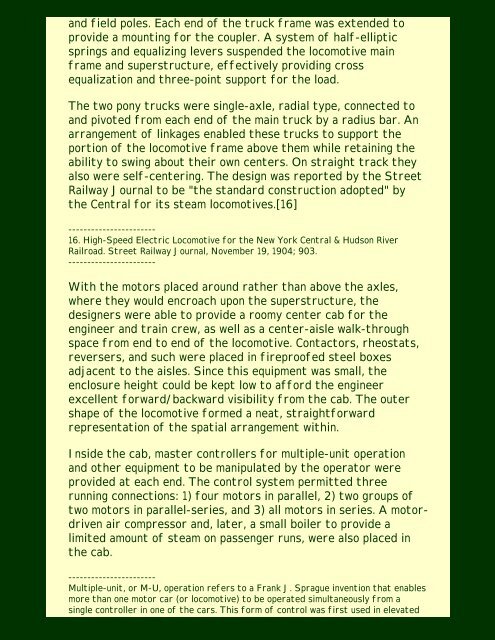
and field poles. Each end of the truck frame was extended to<br />
provide a mounting for the coupler. A system of half-elliptic<br />
springs and equalizing levers suspended the locomotive main<br />
frame and superstructure, effectively providing cross<br />
equalization and three-point support for the load.<br />
The two pony trucks were single-axle, radial type, connected to<br />
and pivoted from each end of the main truck by a radius bar. An<br />
arrangement of linkages enabled these trucks to support the<br />
portion of the locomotive frame above them while retaining the<br />
ability to swing about their own centers. On straight track they<br />
also were self-centering. The design was reported by the Street<br />
Railway Journal to be "the standard construction adopted" by<br />
the Central for its steam locomotives.[16]<br />
-----------------------<br />
16. High-Speed Electric Locomotive for the New York Central & Hudson River<br />
Railroad. Street Railway Journal, November 19, 1904; 903.<br />
-----------------------<br />
With the motors placed around rather than above the axles,<br />
where they would encroach upon the superstructure, the<br />
designers were able to provide a roomy center cab for the<br />
engineer and train crew, as well as a center-aisle walk-through<br />
space from end to end of the locomotive. Contactors, rheostats,<br />
reversers, and such were placed in fireproofed steel boxes<br />
adjacent to the aisles. Since this equipment was small, the<br />
enclosure height could be kept low to afford the engineer<br />
excellent forward/backward visibility from the cab. The outer<br />
shape of the locomotive formed a neat, straightforward<br />
representation of the spatial arrangement within.<br />
Inside the cab, master controllers for multiple-unit operation<br />
and other equipment to be manipulated by the operator were<br />
provided at each end. The control system permitted three<br />
running connections: 1) four motors in parallel, 2) two groups of<br />
two motors in parallel-series, and 3) all motors in series. A motordriven<br />
air compressor and, later, a small boiler to provide a<br />
limited amount of steam on passenger runs, were also placed in<br />
the cab.<br />
-----------------------<br />
Multiple-unit, or M-U, operation refers to a Frank J. Sprague invention that enables<br />
more than one motor car (or locomotive) to be operated simultaneously from a<br />
single controller in one of the cars. This form of control was first used in elevated