198927 SC Ladder INSTALLATION INSTRUCTIONS.pdf - Westeel
198927 SC Ladder INSTALLATION INSTRUCTIONS.pdf - Westeel
198927 SC Ladder INSTALLATION INSTRUCTIONS.pdf - Westeel

Create successful ePaper yourself
Turn your PDF publications into a flip-book with our unique Google optimized e-Paper software.
Part Number: <strong>198927</strong><br />
Revision: 5<br />
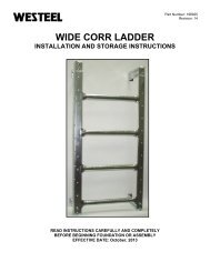
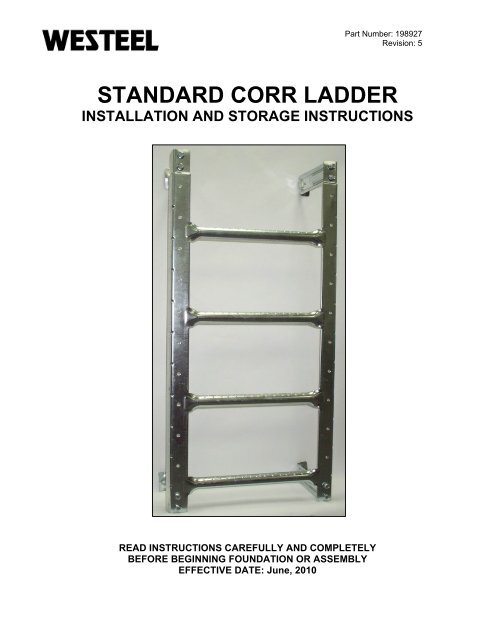
STANDARD CORR LADDER<br />
<strong>INSTALLATION</strong> AND STORAGE <strong>INSTRUCTIONS</strong><br />
READ <strong>INSTRUCTIONS</strong> CAREFULLY AND COMPLETELY<br />
BEFORE BEGINNING FOUNDATION OR ASSEMBLY<br />
EFFECTIVE DATE: June, 2010
TABLE OF CONTENTS<br />
Description<br />
Table of Contents ………………………………………………………….……………………………… 2<br />
New in This Manual ………………………………………………………….…………………………… 3<br />
Warranty ..............………………………………………………………….……………………………… 4 & 5<br />
Disclaimers ..........………………………………………………………….……………………………… 6<br />
Critical Assembly .………………………………………………………….……………………………… 7<br />
Product Storage ...………………………………………………………….……………………………… 8 & 9<br />
Important Notes ...………………………………………………………….……………………………… 10<br />
<strong>Ladder</strong> System Safety Requirement ……………………………………..…………………………...… 11<br />
Section “A”:<br />
<strong>Ladder</strong> Installation For Flat Bottom Bin ……………………….……………………………... 12<br />
Detail A1 ………………………………………………………….……………………………… 13<br />
Detail 1 and 2 ………..………………………………………………………………………….. 14<br />
Detail A2 – A4 …………………………………………………….…………………………….. 15<br />
Section “B”:<br />
For <strong>Ladder</strong>s Terminating 1 Tier from the Ground ……………..……………………………. 16<br />
Section “C”:<br />
For <strong>Ladder</strong>s Terminating at the Ground or at the Bin/Hopper Connection ….…………… 17<br />
Section “D”:<br />
<strong>Ladder</strong> Cage Installation for Flat Bottom Bin …………………………………...…………… 18<br />
Detail D1 and D2 ……………………………………………………………………………….. 19<br />
Section “E”:<br />
<strong>Ladder</strong> Cage Installation for Hopper Bins at Bin/Hopper Connection ..……...…………… 20<br />
Detail E1 and E2 ………………………………………………………………………………... 21<br />
Section “F”:<br />
<strong>Westeel</strong> Hopper Make-up Packages …………………………………..…...…...…………… 22<br />
Section “F1”:<br />
Angle Bracket & Foundation Attachment Details ……………………..….….…...………… 23<br />
Section “G”:<br />
Block-off Plate Installation ………………………..……………………..…...…...…………… 24<br />
Parts Lists ………………………………………..………………………...………………………………. 25 & 26<br />
Parts Identification ………………………………...………………………..…………………………….. 27<br />
Page 2
NEW IN THIS MANUAL<br />
• Modified "Warranty" section<br />
Page 3
LIMITED WARRANTY<br />
<strong>Westeel</strong> Division of Vicwest Operating Limited Partnership ("<strong>Westeel</strong>") warrants products that it<br />
has manufactured and/or that are branded with its name (the "goods") subject to the following<br />
terms and limitations, (the "warranty"):<br />
1. Duration of Warranty. The duration of the warranty is limited as follows:<br />
Galvanized Bins<br />
EasyCheck<br />
EasyFlow<br />
EasyAer<br />
Floors<br />
SeedStor-K Cones<br />
Paint<br />
Structural<br />
SeedStor Cones<br />
Paint<br />
Structural<br />
Retro/Econo Cones<br />
Structural<br />
Paint<br />
Smooth Wall Bins<br />
Paint<br />
Structural<br />
12 months<br />
12 months<br />
24 months<br />
12 months<br />
12 months<br />
12 months<br />
30 months<br />
30 months<br />
10 years<br />
12 months<br />
no warranty<br />
30 months<br />
10 years<br />
The duration of the warranty will run from the date of purchase from a dealer or distributor<br />
authorized by <strong>Westeel</strong> (the "warranty period").<br />
2. Limitation of Remedies Replacement. Within the warranty period, <strong>Westeel</strong> will replace<br />
the goods and/or original manufactured components thereof which are found, to <strong>Westeel</strong>'s<br />
satisfaction, to be defective. <strong>Westeel</strong> is not responsible for direct, indirect, special,<br />
consequential, or any other damages of any kind, including personal injury to any<br />
individual, howsoever caused, including caused by transportation of the goods for repair<br />
or replacement<br />
3. Procedure for Obtaining Service. In the event of a warranty claim, the purchaser must<br />
complete any and all information required by <strong>Westeel</strong> in order to properly assess or<br />
investigate the claim. <strong>Westeel</strong> will not be responsible for the removal of any of the goods<br />
found to be defective, or transportation charges to and from <strong>Westeel</strong>'s authorized dealer<br />
or distributor, or for installation of any replacement goods and/or parts furnished under the<br />
warranty.<br />
Page 4
Limitations as to Scope of Warranty. The warranty does not extend to defects or damage<br />
caused, in whole or in part, by:<br />
i. use of a kind and/or to a degree not reasonably expected to be made of the goods;<br />
ii.<br />
iii.<br />
iv.<br />
improper storage of the goods both prior to and after purchase;<br />
damage caused by, or in the course of, installation or assembly;<br />
any use of the goods which is not an intended use as specified in <strong>Westeel</strong>'s<br />
published product literature, or otherwise specified by <strong>Westeel</strong> in writing;<br />
v. any equipment attached to or used in conjunction with the goods;<br />
vi.<br />
vii.<br />
viii.<br />
ix.<br />
any field modifications or substitutions to original bin components;<br />
inadequate ventilation or any other circumstance not in keeping with proper<br />
maintenance and/or use of the goods;<br />
Acts of God, accident, neglect or abuse of the goods by the purchaser and/or any<br />
other individual or entity; or<br />
Any use or installation inconsistent with <strong>Westeel</strong>’s Standard Disclaimers.<br />
4. Limitations as to Manufacturer. The warranty does not cover products sold by <strong>Westeel</strong><br />
that are not manufactured by <strong>Westeel</strong>. In those circumstances, the purchaser is referred<br />
to the manufacturer of those products.<br />
6. Limitation of Implied Warranties and Other Remedies. To the extent allowed by law,<br />
neither <strong>Westeel</strong> nor its dealers, nor any company affiliated with <strong>Westeel</strong> makes any<br />
warranties, representations, or promises as to the quality, performance, or freedom from<br />
defect of any Product covered by this Warranty.<br />
WESTEEL HEREBY DI<strong>SC</strong>LAIMS, TO THE EXTENT APPLICABLE, ANY AND ALL<br />
IMPLIED WARRANTIES OF MERCHANTABILITY AND FITNESS FOR A PARTICULAR<br />
PURPOSE. A PURCHASER’S ONLY REMEDIES IN CONNECTION WITH THIS<br />
WARRANTY ARE THOSE SET FORTH IN THIS WARRANTY. IN NO EVENT WILL<br />
WESTEEL, ITS DEALERS, OR ANY COMPANY AFFILIATED WITH WESTEEL BE<br />
LIABLE FOR INCIDENTIAL, CONSEQUENTIAL OR PUNITIVE DAMAGES.<br />
Some jurisdictions do not allow waivers of certain warranties, so the above waivers may<br />
not apply to you. In that event, any implied warranties are limited in duration to ninety<br />
(90) days from delivery of the products. You may also have other rights which vary from<br />
jurisdiction to jurisdiction.<br />
7. Exclusive Warranty. This warranty is the only warranty provided by <strong>Westeel</strong> and all<br />
other warranties and/or commitments, whether express or implied and no matter by whom<br />
made, statutory or otherwise, are subsumed and replaced by it and are of no legal effect.<br />
If any provision of the warranty is held by a court of competent jurisdiction to be void or<br />
unenforceable, in whole or in part, such provision shall be deemed severable and will not<br />
affect or impair the legal validity of any other provision of the warranty.<br />
Page 5
DI<strong>SC</strong>LAIMERS<br />
Foundation Design<br />
The foundations for the stiffened bin models are based on 4000 lbs. per sq. ft. (192 kPa) soil<br />
bearing capacity. All foundation designs use 3000 lbs. per sq. in. (21 MPa) ultimate compressive<br />
strength (after 28 days) for concrete and 43,500 lbs. per sq. in. (300 MPa) re-bar. The foundation<br />
designs included in this manual are suggestions only, and will vary according to local soil<br />
conditions. <strong>Westeel</strong> will not assume any liability for results arising from their use.<br />
IMPORTANT:Foundation should be uniform and level. Level should not<br />
vary by more than ¼" over a span of four feet under the<br />
bottom ring angle. Any variance from level must be shimmed<br />
under upright base assembly. If being utilized to support a full floor<br />
aeration system, this levelness requirement should extend across<br />
the complete floor area.<br />
Method of Erection<br />
The recommendations for erecting <strong>Westeel</strong> Grain Bins should be closely followed to achieve the<br />
full strength of the bin and to achieve adequate weather sealing. Warranty is void if the<br />
recommendations are not followed including but not limited to:<br />
1. Wall sheets and/or uprights, which are not specified for a given tier, are used.<br />
2. Foundations are found to be inadequate or out-of-level.<br />
3. Anchor bolts (cast-in-place, drill-in, chemical type or other) are found to be inadequate.<br />
4. Off-center loading or unloading is used. This does not apply to the use of approved side<br />
unloading systems.<br />
5. Materials stored are not free-flowing or have a compacted bulk density greater than 55<br />
lbs/ft 3 (880 kg/m 3 ).<br />
If using Bin Jacks: Always lift on an upright. Choose a hoist with a suitable capacity for the<br />
expected empty bin deadload. Make sure the rated capacity of the hoist is not<br />
exceeded.<br />
These <strong>Westeel</strong> Grain Bins are designed for:<br />
Design<br />
1. Non-corrosive, free-flowing materials up to 55 lbs/ft 3 (880 kg/m 3 ) average compacted bulk<br />
density.<br />
2. Maximum horizontal gusted wind speed of 94 mph (151 km/h).<br />
3. Seismic zone 2a (U.B.C. 1997).<br />
4. 15.0 lbs/ft 2 (.72 kPa) roof snow load.<br />
24.0 lbs/ft 2 (1.15 kPa) roof snow load when the optional roof stiffening rings are installed.<br />
5. 4000 lbs. (17.8 kN) evenly distributed on peak ring for 15’ – 24’ bins.<br />
5000 lbs. (22.2 kN) evenly distributed on peak ring for 27’ – 48’ bins.<br />
Page 6
Site and Assembly<br />
Unless otherwise specifically provided in writing, <strong>Westeel</strong> does not take responsibility for any<br />
defects or damages to any property, or injury to any persons, arising from or related to any site or<br />
assembly considerations, including but not limited to:<br />
• Bin location and bin siting;<br />
• Soil conditions and corresponding foundation requirements (note that the examples<br />
provided in manuals are for specifically stated soil conditions);<br />
• Bin assembly (<strong>Westeel</strong> recommends the use of qualified bin installers; contact<br />
<strong>Westeel</strong> for information on installers in your area);<br />
• Field modifications or equipment additions that affect the bin structure; and<br />
• Interconnections with neighbouring structures.<br />
• Compliance with all applicable safety standards, including but not limited to fall<br />
restraint systems (ladders or other systems). Local safety authorities should be<br />
contacted as standards vary between jurisdictions.<br />
Critical Assembly Requirements<br />
1. Local code and jurisdictional requirements that are applicable to the grain bin installation<br />
must be adhered to.<br />
2. Foundations must be designed for the loads being imparted to them, and for local soil<br />
conditions. <strong>Westeel</strong> foundation guidelines are for a set of stated conditions and may not<br />
be applicable to local conditions.<br />
3. A foundation must provide uniform and level support to the grain bin structure being<br />
supported. Surface imperfections causing gapping must be remedied. This may involve,<br />
but not be limited to - grouting under the bottom ring of a non-stiffened bin, and shimming<br />
under the uprights of a stiffened bin or under the legs of a hopper.<br />
4. If extending an existing bin, ensure that the foundation is adequate for the increased loads<br />
that will be subjected to it.<br />
5. If installing an existing bin on a hopper, ensure that the bin is designed for a hopper<br />
application, and that the foundation is capable of withstanding the substantial point loads<br />
that the hopper legs apply. If uprights are present, ensure that they are supported.<br />
6. Ensure that the proper hardware is utilized for all bolted connections. Refer to the<br />
‘Hardware “Where Used” Chart’ in the Installation Manual. If a shortage occurs do not<br />
substitute. Take the necessary steps to obtain the proper hardware. Ensure nuts are<br />
tightened to the required torque values as provided in the Installation Manual.<br />
7. Refer to the appropriate Installation Manual to ensure a safe, proper structure, in<br />
particular but not exclusively for the wall sheet and upright layouts. Do not deviate from<br />
the layouts provided.<br />
8. Ensure that an integral end-to-end connection exists between mating uprights.<br />
Successive uprights must not overlap.<br />
Page 7
9. Vertical tolerances between uprights and wall sheets are tight. This can be affected by<br />
“jacking” techniques, which can allow the tolerance to grow or shrink depending on the<br />
technique used. The gapping between successive uprights must be monitored to ensure<br />
that upright holes align with bin sheet holes.<br />
10. When installing roof stiffening rings, and if it is necessary to shorten the stiffening ring<br />
tubes, shorten them as little as possible. Initially the nuts on the expanders should be<br />
centered and as close together as possible. When tightening, share the amount of takeup<br />
between expanders such that the nuts remain centered, and the amount of<br />
engagement between all expanders on the same ring is equalized.<br />
11. Before anchoring the bin to the foundation, ensure that the bin is round. The maximum<br />
variation from perfect roundness is 3/4" on the radius (see details in "wall sheet and<br />
bottom angle " section of manual). Locate anchor bolts towards the outside of the anchor<br />
bolt holes (away from bin) to permit the incremental expansion that can occur with the<br />
initial filling.<br />
Grain Bin Use<br />
1. Do not off-center unload a grain bin. It is imperative to unload from the center of the bin<br />
first, until as much grain as possible has been removed, and only then proceed to unload<br />
from the next closest unload gate to the center. Continue utilizing the unload gates in<br />
succession from the center towards the outside. Gate control mechanisms should be<br />
clearly marked and interconnected to prevent an external gate from being opened first.<br />
2. The only exception to center unloading is when a properly designed and installed side<br />
draw system is utilized. However, as bins tend to go out of round when employing side<br />
draws, the bin must be completely emptied before refilling.<br />
3. When unloading a bin with a mobile auger through a properly designed auger chute, the<br />
entry end of the auger should be pushed into the center of the bin before the auger is<br />
engaged. Slower rates of flow are preferable and should not exceed the capacity of an 8”<br />
auger.<br />
4. Ensure that the inner door panels of grain bin doors are completely closed and latched<br />
before filling the grain bin.<br />
5. Never enter a loaded grain bin for any reason. Grain can be a killer.<br />
Rust on Galvanized Parts<br />
Product Storage<br />
1. White rust forms when moisture is allowed to collect on galvanized surfaces that have yet to<br />
develop the durable zinc oxide layer. This zinc oxide layer naturally occurs as the surface<br />
interacts with carbon dioxide, and is characterized over time by the dull grey appearance that<br />
weathered galvanized surfaces get.<br />
2. Parts that are not well ventilated or well drained can collect water between surfaces and<br />
develop white rust.<br />
3. White rust is not a structural concern if its development is stopped in the early stages. A<br />
light film or powdery residue can occur after a period of heavy rainfall or a short time of<br />
improper storage. If white rust has started to develop, separate parts and wipe off any<br />
moisture. Next, using a clean cloth, apply a thin layer of petroleum jelly or food-grade oil<br />
to the entire part.<br />
Page 8
4. If moisture is left on parts, this white rust can become more aggressive and turn into red<br />
rust. Red rust can cause degradation in the material and become a structural concern.<br />
Any parts that have red rust should be replaced immediately.<br />
Storage Guidelines<br />
1. Keep all bundles dry before assembly of the<br />
bin. Start assembly as soon as possible. Do not<br />
lay bundles on the bare ground, raise all bundles<br />
6” – 8” off the ground on wood blocks or timbers.<br />
Store curved wall sheets ‘hump-up’. All other<br />
bundles material should be placed so that they are<br />
well sloped to promote good drainage.<br />
2. Roof sheets must be elevated at least 12” at the<br />
small end of the sheets.<br />
3. Temporary storage can be provided by erecting<br />
a simple framework supporting a waterproof tarp.<br />
4. All bin boxes, ladder boxes and hardware boxes should be stored inside. These are not<br />
waterproof, and will deteriorate in normal weather conditions, allowing moisture to contact<br />
the parts inside.<br />
If Parts Become Wet<br />
1. If goods become submerged or wet, the<br />
bundles should be opened as soon as possible,<br />
sheets or material separated and dried. Keep<br />
separated until assembly. Brace goods<br />
properly so as to avoid damage or injury from<br />
material falling when in storage.<br />
2. Any boxed goods that become wet should be dried and stored in a new box that is free of<br />
moisture.<br />
3. In addition to wiping down wallsheets, a food-grade oil can also be applied with a clean,<br />
lint-free cloth. This will assist in preventing any further moisture from contacting the<br />
galvanizing on the steel. Due to safety concerns with installation and use, <strong>Westeel</strong> does<br />
not recommend the use of oil on other parts such as roof sheets and safety ladders.<br />
Page 9
IMPORTANT NOTES<br />
1. In order to maintain your wall sheets in good condition separate sheets and allow air<br />
circulation between them. Store sheets in a dry place. Do not store sheets with sheet<br />
ends pointing upwards.<br />
2. To keep an even pressure on walls, the bin must always be unloaded from the centre.<br />
3. Contact local power officials for minimum power line clearance.<br />
4. See "Disclaimers - Design" for materials which can be stored.<br />
5. Tighten all bolts to the recommended torque setting (see Recommended Bolt Torques<br />
table in Appendix).<br />
6. Do not locate grain bin close to high buildings, which might cause snow to fall onto or<br />
build up on the roof of the grain bin. Consider future expansion and allow space for<br />
loading and unloading of the bin. Your dealer and local government agricultural<br />
consultants can help you plan your storage system for maximum efficiency.<br />
Shortages and Damaged Parts;<br />
Report damaged parts or shortages immediately to the delivering carrier, followed by a<br />
confirming letter requesting inspection by the carrier, if required. Order any replacement parts<br />
immediately to ensure that assembly will not be held up by missing parts. All parts will be<br />
charged for and credit will be issued by party at fault - no credit will be issued if freight bill are<br />
signed as received in good condition.<br />
Order Optional Equipment;<br />
Optional equipment such as unloading augers, aeration equipment, anchor bolts, foundation<br />
sealant, external ladders, safety cage and platforms, etc., should all be on site and checked<br />
before assembly starts. Plan your installation in advance. For details, see assembly<br />
instructions supplied with optional equipment.<br />
List of Warning Decals;<br />
236564<br />
236088<br />
Consistent with <strong>Westeel</strong> Limited’s policy of continued research and development of our<br />
products, we reserve the right to modify or change information contained in this publication<br />
without notice.<br />
Page 10
WARNING<br />
Falling hazard<br />
Do not climb ladder without<br />
an approved fall arresting<br />
device in place.<br />
Consult dealer or local<br />
Health and Safety Authority<br />
for further information.<br />
AVERTISSEMENT<br />
Risque de chute<br />
Ne montez pas sur l’échelle si<br />
aucun dispositif antichute<br />
approuvé n’est en place.<br />
Consultez le marchand ou les<br />
services de santé et de sécurité<br />
locaux pour de plus amples<br />
renseignements.<br />
234567<br />
LADDER SYSTEM SAFETY REQUIREMENTS<br />
Falling hazard<br />
WARNING<br />
Do not climb ladder without<br />
an approved fall arresting<br />
device in place.<br />
Consult dealer or local<br />
Health and Safety Authority<br />
for further information.<br />
AVERTISSEMENT<br />
Risque de chute<br />
Ne montez pas sur l’échelle si<br />
aucun dispositif antichute<br />
approuvé n’est en place.<br />
Consultez le marchand ou les<br />
services de santé et de sécurité<br />
locaux pour de plus amples<br />
renseignements.<br />
234567<br />
WARNING<br />
65”<br />
IMPORTANT: Regulations require that fixed ladders over a<br />
certain height must be outfitted with platforms and cages, or<br />
other approved fall arresting devices. For information on the<br />
specific requirements applicable in the jurisdiction in which a<br />
ladder is to be used, please consult the local health and safety<br />
authority. For information on how to contact your local authority, please ask your dealer.<br />
Affix warning label (234567) to the wall sheets beside the ladder where it will be most visible.<br />
Suggest locating at eye level (about 5½’ off the ground) on a flat bottom bin, or just above the<br />
bin/hopper interface on a hopper bin. Wipe wall sheet free of oil before applying.<br />
Product safety labels should be replaced when they are no longer legible. If the ‘<strong>Ladder</strong> Safety<br />
Label’ requires replacement, order part number 234567 from your local <strong>Westeel</strong> dealer and affix<br />
as directed.<br />
Page 11
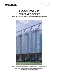
SECTION “A”<br />
LADDER <strong>INSTALLATION</strong> FOR FLAT BOTTOM STANDARD CORR BIN<br />
DETAIL A1<br />
DETAIL A2<br />
DETAIL A3<br />
APPLY WARNING<br />
LABEL AS SHOWN<br />
ON PAGE 3<br />
SECTIONS<br />
“B” OR “C”<br />
WARNING AVERTISSEMENT<br />
Falling hazard<br />
Risque de chute<br />
Ne montez pas sur l’échelle si<br />
Do not climb ladder without<br />
aucun dispositif antichute<br />
an approved fall arresting<br />
approuvé n’est en place.<br />
device in place.<br />
Consultez le marchand ou les<br />
Consult dealer or local<br />
services de santé et de sécurité<br />
Health and Safety Authority<br />
locaux pour de plus amples<br />
for further information.<br />
renseignements.<br />
NOTE:<br />
1. This eaves rail configuration is compatible with cage system.<br />
2. For ladders terminating 1 tier from the ground – see section “B”.<br />
3. For ladders terminating at the ground or at the bin/hopper connection – see section “C”.<br />
4. If extending the ladder to the ground, the ladder block-off plate (P/N 234530) should be installed to prevent unauthorized usage.<br />
DETAIL A4<br />
234567<br />
Page 12
DRILL IN LADDER SUPPORT ARM<br />
BRACKETS (P/N 234518) ALONG<br />
ROOF RIBS WHERE CONVENIENT<br />
LADDER SUPPORT<br />
ARM (P/N 234504)<br />
LADDER SUPPORT ARM<br />
(P/N 234504)<br />
BOLT LADDER SUPPORT<br />
ARM BRACKETS (P/N 234518)<br />
TO EXISTING EAVE BOLT<br />
LOCATIONS WHERE<br />
CONVENIENT<br />
DETAIL 1<br />
3/8” x 2½” BOLT (PASS THROUGH<br />
RAIL LOCATION ONLY)<br />
TOP<br />
SLIDE LADDER SUPPORT ARM CLIPS UP OR DOWN<br />
THE PASS THROUGH RAILS TO MATCH LOWER<br />
<strong>INSTALLATION</strong> POINTS BEFORE TIGHTENING<br />
LADDER SUPPORT<br />
ARM (P/N 234504)<br />
PLASTIC PIPE CAP<br />
(P/N 234559)<br />
LADDER SUPPORT<br />
ARM CLIP (P/N 234517)<br />
3/8” x 1” BOLT<br />
3/8” x 1” BOLT<br />
PASS THROUGH RAIL<br />
LOCATIONS (P/N 234505)<br />
3/8” x 2½” BOLT (PASS<br />
THROUGH RAIL<br />
LOCATIONS ONLY)<br />
5”<br />
IMPORTANT FIRST STEP: THE TOP LADDER CLIPS<br />
MUST BE MOVED DOWN TWO CORRUGATIONS (5”)<br />
BELOW THE TOP HORIZONTAL WALL SEAM IN ORDER<br />
TO CLEAR THE EAVE. THE WALL SHEET MUST BE<br />
DRILLED AT THIS LOCATION. THE 5” IS REQUIRED TO<br />
LINE UP WITH THE SUPPORT LOCATIONS ON THE<br />
MATING CAGE SYSTEM. USE 3/8” x 1½” BOLTS WITH 2<br />
NUTS. USE 1 NUT AS A SPACER BETWEEN THE WALL<br />
SHEET AND LADDER CLIPS AND SECURE WITH 2 ND NUT.<br />
DETAIL A1<br />
3/8” x 1” BOLT<br />
FOR TOP CLIP <strong>INSTALLATION</strong><br />
DETAILS SEE DETAIL 2<br />
Page 13
PLACE SUPPORT ARMS<br />
ON OUTSIDE OF LADDER<br />
SUPPORT ARM CLIPS. DO<br />
NOT PLACE BETWEEN<br />
BANDS OF CLIP.<br />
LADDER SUPPORT<br />
ARMS (P/N 234504)<br />
3/8” x 1” BOLT<br />
(TYPICAL)<br />
PASS THROUGH<br />
RAIL (P/N 234505)<br />
LADDER SUPPORT ARM<br />
CLIP (P/N 234517)<br />
DETAIL 1<br />
3/8” HEAVY HEX NUTS<br />
LADDER CLIP<br />
3/8” x 1½” BOLT<br />
DETAIL 2<br />
Page 14
NOTE THE ORIENTATION OF THE EAVES RAIL<br />
PLASTIC PIPE CAP<br />
(P/N 234559)<br />
LEFT RAIL<br />
RIGHT RAIL<br />
MIDDLE CLIPS MOUNT TO<br />
HORIZONTAL WALL SEAMS<br />
LADDER PASS<br />
THROUGH RAIL<br />
(P/N 234505)<br />
A<br />
A<br />
B<br />
B<br />
DETAIL A2<br />
FRONT VIEW – LADDER ONLY<br />
DETAIL A3<br />
3/8” x 2½” BOLT<br />
(PASS THROUGH<br />
RAIL LOCATION)<br />
SECTION A – A<br />
3/8” x 1½” BOLT<br />
SWAGED END OF LOWER<br />
LADDER SECTION FITS INTO<br />
UPPER LADDER SECTION.<br />
FLANGES ON LADDER<br />
CLIPS POINT TOWARDS<br />
THE OUTSIDE<br />
3/8” x 1” BOLT<br />
SECTION B – B<br />
Page 15
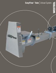
SECTION “B”<br />
FOR LADDERS TERMINATING 1 TIER FROM THE GROUND<br />
4 TIERS 5 TIERS 6 TIERS<br />
MOVE BOTTOM CLIPS UP 5”<br />
(2 CORRUGATIONS) ABOVE<br />
THE HORIZONTAL WALL<br />
SHEET SEAM AND DRILL IN<br />
EITHER MOUNT THE CLIPS AT THE<br />
HORIZONTAL WALL SHEET SEAM AND CUT<br />
THE BOTTOM LADDER SECTION AS<br />
SHOWN OR MOVE THE CLIPS DOWN 10” TO<br />
THE ALTERNATE LOCATION AND DRILL IN.<br />
EITHER MOUNT THE CLIPS AT THE<br />
HORIZONTAL WALL SHEET SEAM AND CUT<br />
THE BOTTOM LADDER SECTION AS SHOWN<br />
OR INSTALL ADDITIONAL CLIPS 5” ABOVE THE<br />
BOTTOM WALL SHEET SEAM AND DRILL IN.<br />
5.0”<br />
10.0”<br />
CUT HERE<br />
CUT HERE<br />
APPROX. 10.0”<br />
APPROX. 24.0”<br />
ALTERNATE CLIP LOCATION<br />
(DO NOT CUT LADDER)<br />
5.0”<br />
ALTERNATE CLIP LOCATION<br />
(DO NOT CUT LADDER)<br />
7 TIERS 8 TIERS<br />
EITHER MOUNT THE CLIPS AT THE<br />
HORIZONTAL WALL SHEET SEAM AND CUT<br />
THE BOTTOM LADDER SECTION AS<br />
SHOWN OR MOVE THE CLIPS DOWN 5” TO<br />
THE ALTERNATE LOCATION AND DRILL IN.<br />
5.0”<br />
MOVE BOTTOM CLIPS UP 5”<br />
(2 CORRUGATIONS) ABOVE<br />
THE HORIZONTAL WALL<br />
SHEET SEAM AND DRILL IN.<br />
5.0” CUT HERE<br />
APPROX. 8.0”<br />
ALTERNATE CLIP LOCATION<br />
(DO NOT CUT LADDER)<br />
Page 16
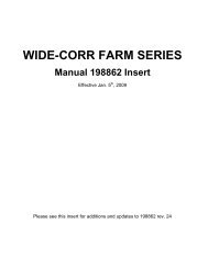
SECTION “C”<br />
FOR LADDERS TERMINATING AT THE GROUND OR AT THE BIN/HOPPER CONNECTION<br />
4 TIERS 5 TIERS 6 TIERS<br />
DRILL<br />
DRILL<br />
5.0”<br />
CUT HERE IF NOT<br />
COMBINING WITH<br />
WESTEEL HOPPER<br />
LADDER SYSTEM<br />
5.0”<br />
CUT HERE IF NOT<br />
COMBINING WITH<br />
WESTEEL HOPPER<br />
LADDER SYSTEM<br />
RING ANGLE OR<br />
HOPPER CONNECTION<br />
POINT<br />
NOTE:<br />
MOVE BOTTOM CLIPS UP 5” (2<br />
CORRUGATIONS) ABOVE THE<br />
HORIZONTAL WALL SHEET<br />
SEAM AND DRILL IN<br />
(REQUIRED FOR ALL OPTIONS)<br />
APPROX. 12.0”<br />
RING ANGLE OR<br />
HOPPER CONNECTION<br />
POINT<br />
NOTE:<br />
MOVE BOTTOM CLIPS UP 5” (2<br />
CORRUGATIONS) ABOVE THE<br />
HORIZONTAL WALL SHEET<br />
SEAM AND DRILL IN<br />
(REQUIRED FOR ALL OPTIONS)<br />
APPROX. 28.0”<br />
DRILL<br />
25.0”<br />
5.0”<br />
RING ANGLE OR<br />
HOPPER CONNECTION<br />
POINT<br />
7 TIERS 8 TIERS<br />
NOTE:<br />
MOVE BOTTOM CLIPS UP 5” (2<br />
CORRUGATIONS) ABOVE THE<br />
HORIZONTAL WALL SHEET<br />
SEAM AND DRILL IN<br />
(REQUIRED FOR ALL OPTIONS)<br />
DRILL<br />
DRILL<br />
5.0”<br />
CUT HERE IF NOT<br />
COMBINING WITH<br />
WESTEEL HOPPER<br />
LADDER SYSTEM<br />
5.0”<br />
CUT HERE IF NOT<br />
COMBINING WITH<br />
WESTEEL HOPPER<br />
LADDER SYSTEM<br />
RING ANGLE OR<br />
HOPPER CONNECTION<br />
POINT APPROX. 12.0”<br />
RING ANGLE OR<br />
HOPPER CONNECTION<br />
POINT<br />
NOTE:<br />
MOVE BOTTOM CLIPS UP 5” (2<br />
CORRUGATIONS) ABOVE THE<br />
HORIZONTAL WALL SHEET<br />
SEAM AND DRILL IN<br />
(REQUIRED FOR ALL OPTIONS)<br />
NOTE:<br />
MOVE BOTTOM CLIPS UP 5” (2<br />
CORRUGATIONS) ABOVE THE<br />
HORIZONTAL WALL SHEET<br />
SEAM AND DRILL IN<br />
(REQUIRED FOR ALL OPTIONS)<br />
APPROX. 24.0”<br />
Page 17
SECTION “D”<br />
LADDER CAGE <strong>INSTALLATION</strong> FOR FLAT BOTTOM STANDARD CORR BIN<br />
48.0”<br />
25.0”<br />
30.0”<br />
30.0”<br />
30.0”<br />
3 RD HORIZONTAL SEAM<br />
DETAIL D2<br />
90.0”<br />
NOTE:<br />
1. This cage system is compatible with the “pass through rail” version of ladder system only.<br />
2. Bottom cage aligns with the 3 rd horizontal seam from the bottom.<br />
3. If ladder terminates at the ground use in conjunction with ladder block-off plate (234530).<br />
Page 18
3/8” x 1” BOLT<br />
3/8” x 1½” BOLT<br />
BOLT THIS<br />
LOCATION<br />
LAST<br />
TOP VIEW<br />
(CAGE ONLY)<br />
RAIL<br />
LADDER SUPPORT<br />
ARM CLIPS<br />
LADDER SUPPORT<br />
ARM<br />
CAP<br />
TOP CAGE HOOP<br />
(P/N 234511)<br />
THE UPPER CAGE SECTION<br />
USES THE 48” (MEASURED FROM<br />
HOLE-TO-HOLE) VERTICAL<br />
SUPPORTS. THERE ARE SEVEN<br />
SUPPORTS PER CAGE SECTION<br />
48” VERTICAL SUPPORT<br />
5.0”<br />
LADDER CLIP<br />
STANDARD CAGE HOOP<br />
(P/N 234512)<br />
DETAIL D1<br />
THE SECOND CAGE<br />
SECTION USES 25”<br />
VERTICAL SUPPORTS<br />
CAGE HOOP BOLTS<br />
INTO LADDER CLIPS<br />
USE 3/8” x 1” BOLT<br />
NOTE:<br />
FOR LADDER CLIPS, SUPPORT ARM BRACKETS AND CLIPS<br />
<strong>INSTALLATION</strong> (SEE DETAIL A1)<br />
THE REMAINING CAGE<br />
SECTIONS USE THE<br />
STANDARD 30” VERTICAL<br />
SUPPORTS<br />
STANDARD CAGE HOOP<br />
(P/N 234512)<br />
BOTTOM CAGE HOOP<br />
(P/N 234513)<br />
DETAIL D2<br />
VERTICAL SUPPORTS ARE<br />
POSITIONED ON THE INSIDE OF<br />
THE CAGE HOOPS WITH THE<br />
LEGS POINTING OUTWARDS<br />
BOTTOM VIEW<br />
(STANDARD HOOPS NOT SHOWN)<br />
Page 19
SECTION “E”<br />
LADDER CAGE <strong>INSTALLATION</strong> FOR STANDARD CORR HOPPER BINS WHERE CAGE TERMINATES AT BIN /HOPPER CONNECTION<br />
DETAIL E1<br />
48.0”<br />
25.0”<br />
30.0”<br />
30.0”<br />
25.0”<br />
DETAIL E2<br />
NOTE:<br />
1. This cage system is compatible with “pass through rail” version of ladder system only.<br />
2. For corresponding ladder assembly see section “C”.<br />
Page 20
3/8” x 1” BOLT<br />
3/8” x 1½” BOLT<br />
BOLT THIS<br />
LOCATION<br />
LAST<br />
TOP VIEW<br />
(CAGE ONLY)<br />
RAIL<br />
LADDER SUPPORT<br />
ARM CLIPS<br />
LADDER SUPPORT<br />
ARM<br />
CAP<br />
TOP CAGE HOOP<br />
(P/N 234511)<br />
BOTTOM LADDER CLIP ON<br />
BIN MUST BE MOVED UP 5”<br />
HORIZONTAL SEAM AND<br />
DRILL IN<br />
THE UPPER CAGE SECTION<br />
USES THE 48” (MEASURED FROM<br />
HOLE-TO-HOLE) VERTICAL<br />
SUPPORTS. THERE ARE SEVEN<br />
SUPPORTS PER CAGE SECTION<br />
5.0”<br />
48” VERTICAL SUPPORT<br />
5.0”<br />
LADDER CLIP<br />
STANDARD CAGE HOOP<br />
(P/N 234512)<br />
DETAIL E1<br />
THE SECOND CAGE<br />
SECTION USES 25”<br />
VERTICAL SUPPORTS<br />
CAGE HOOP BOLTS<br />
INTO LADDER CLIPS<br />
USE 3/8” x 1” BOLT<br />
NOTE:<br />
FOR LADDER CLIPS, SUPPORT ARM BRACKETS AND CLIPS<br />
<strong>INSTALLATION</strong> (SEE DETAIL A1)<br />
THE REMAINING CAGE<br />
SECTIONS (EXCEPT BOTTOM)<br />
USE THE STANDARD 30”<br />
VERTICAL SUPPORTS<br />
(P/N 234542)<br />
STANDARD CAGE HOOP<br />
(P/N 234512)<br />
25” VERTICAL SUPPORT<br />
(P/N 234543)<br />
BOTTOM CAGE HOOP<br />
(P/N 234513)<br />
DETAIL E2<br />
VERTICAL SUPPORTS ARE<br />
POSITIONED ON THE INSIDE OF<br />
THE CAGE HOOPS WITH THE<br />
LEGS POINTING OUTWARDS<br />
BOTTOM VIEW<br />
(STANDARD HOOPS NOT SHOWN)<br />
Page 21
SECTION “F”<br />
WESTEEL HOPPER MAKE-UP PACKAGES FOR STANDARD CORR BINS<br />
ASSEMBLE UPPER LADDER &<br />
CAGE TIERS AS INDICATED<br />
IN THE FLAT BOTTOM BIN<br />
SECTION “C” & “E”<br />
DETAIL 1<br />
ASSEMBLE UPPER LADDER<br />
& CAGE TIERS AS INDICATED<br />
IN THE FLAT BOTTOM BIN<br />
SECTION “C” & “E”<br />
DETAIL 1<br />
25.0”<br />
A<br />
A<br />
44.0”<br />
HOPPER LEG<br />
DO NOT TRIM LADDERS AT THIS<br />
LOCATION. LET LADDER ENDS<br />
EXTEND BEYOND BIN/HOPPER<br />
CONNECTION<br />
HOPPER LEG<br />
BOTTOM CAGE SECTION<br />
EXTENDS INTO HOPPER AND<br />
ATTACHES TO SUPPORT<br />
CHANNEL. USE 44" VERTICAL<br />
SUPPORTS AT THIS LOCATION<br />
SUPPORT CHANNELS:<br />
14’ x 35° (P/N 234561)<br />
14’ x 45° (P/N 234562)<br />
19’ x 35° (P/N 234562)<br />
SUPPORT CHANNELS<br />
(P/N 234563)<br />
ANGLE BRACKET<br />
(P/N 234522)<br />
ANGLE BRACKET<br />
(P/N 234522)<br />
TRIM BOTTOM LADDER SEGMENT<br />
TO FIT IF NECESSARY<br />
SIDE VIEW FOR:<br />
- 14’ x 35° WELDED HOPPER (P/N 234553)<br />
- 14’ x 45° KNOCK DOWN HOPPER (P/N 234554)<br />
- 19’ x 35° WELDED HOPPER (P/N 234554)<br />
TRIM BOTTOM LADDER SEGMENT<br />
TO FIT IF NECESSARY<br />
SIDE VIEW FOR:<br />
- 19’ x 45° WELDED HOPPER (P/N 234555)<br />
LADDER CLIP<br />
LADDER<br />
MOVE BOTTOM CLIPS UP 5”<br />
(2 CORRUGATIONS) ABOVE<br />
THE HORIZONTAL WALL<br />
SHEET SEAM AND DRILL IN<br />
5.0”<br />
USE 3/8” x 1” BOLTS TO<br />
SECURE LADDER &<br />
BOTTOM CAGE HOOP TO<br />
THE SUPPORT CHANNEL<br />
CAGE HOOP<br />
LADDER<br />
SUPPORT CHANNEL<br />
DETAIL 1<br />
POSITION SUPPORT CHANNELS<br />
SO THAT THEY DO NOT LINE UP<br />
WITH HOPPER LEGS<br />
BOTTOM HOOP<br />
VIEW A – A<br />
(HOPPER LEGS NOT SHOWN)<br />
NOTE:<br />
1. Use in conjunction with block-off plate.<br />
Page 22
SECTION “F1”<br />
ANGLE BRACKET & FOUNDATION ATTACHMENT DETAILS<br />
2 HOLES ON THE BOTTOM OF<br />
LADDER SUPPORT CHANNEL<br />
SPECIFICALLY FOR BOLT<br />
CONNECTION<br />
LADDER SUPPORT<br />
CHANNEL<br />
B<br />
ANGLE BRACKET<br />
B<br />
3.0”<br />
CONCRETE PAD WITH ½” ANCHOR BOLTS<br />
(NOT INCLUDED)<br />
STEEL SKID WITH ¼” TEK <strong>SC</strong>REWS<br />
(NOT INCLUDED)<br />
3/8” x 1” BOLT<br />
ANGLE BRACKET<br />
LADDER SUPPORT<br />
CHANNEL<br />
LADDER<br />
VIEW B – B<br />
Page 23
SECTION “G”<br />
BLOCK-OFF PLATE <strong>INSTALLATION</strong><br />
HINGE/BLOCK-OFF PLATE ASSEMBLY<br />
(VIEWED FROM BACK OF PLATE)<br />
TOP HINGE<br />
SITS ON<br />
TOP OF THE<br />
BLOCK-OFF<br />
PLATE.<br />
BOTTOM<br />
HINGE SITS<br />
BELOW THE<br />
BLOCK-OFF<br />
PLATE.<br />
BOTH HINGES INSTALL POINTING IN THE SAME DIRECTION.<br />
HOWEVER THEY POINT “UP” OR “DOWN” DEPENDING<br />
WHICH SIDE OF LADDER THEY ARE INSTALLED. SHOWN IS<br />
<strong>INSTALLATION</strong> ON LEFT LADDER RAIL.<br />
64.0”<br />
RECOMMENED<br />
HEIGHT 12” – 15”<br />
A<br />
A<br />
BLOCK-OFF PLATE<br />
(P/N 234530)<br />
SIDE VIEW<br />
FRONT VIEW<br />
WALL SHEET<br />
BLOCK-OFF PLATE HINGE<br />
(P/N 234558) BOLTS TO<br />
LADDER RAIL. USE<br />
EXISTING HOLES AT 64”<br />
CENTERS.<br />
0.75”<br />
REF.<br />
LADDER CLIP (OR LADDER<br />
SUPPORT CHANNEL)<br />
PADLOCK REQUIRED<br />
(NOT INCLUDED)<br />
3/8” x ¾” BOLT<br />
AND LOCK NUT<br />
SECTION A–A<br />
NOTE:<br />
1. Align holes on block-off plate hinges with existing holes in ladder rail (64” apart).<br />
2. Do not line up hinges with ladder clips on flat bin models.<br />
3. On hopper bin models, it is necessary to drill into ladder support channels to mount<br />
hinges.Block-off plates can be mounted to swing either way. Shown is mounting on left<br />
ladder rail.<br />
Page 24<br />
BLOCK-OFF PLATE<br />
(P/N 234557)<br />
AFTER BLOCK-OFF PLATE INSTALLED<br />
DRILL MATING 3/8” DIA. HOLE IN LADDER<br />
RAIL USING HOLE IN BLOCK-OFF PLATE<br />
AS A TEMPLATE. THIS IS USED FOR A<br />
PADLOCK.
STANDARD CORR LADDER PARTS LISTINGS<br />
STANDARD CORR LADDER PACKAGES<br />
PASS RAIL<br />
DE<strong>SC</strong>RIPTION 234550-2 234550-3 234550-4 234550-5 234550-6<br />
PACKAGES<br />
234500 LADDER SECTION (44”) 2 3 4 5 6<br />
234541 LADDER CLIPS - <strong>SC</strong> 8 10 14 16 18<br />
234566 LADDER PASS THROUGH RAIL PACKAGE 1 1 1 1 1<br />
234545 HARDWARE PACKAGE 1 1 1 1 1<br />
STANDARD CORR CAGE PACKAGES – FLAT BOTTOM BIN<br />
FLAT BOTTOM<br />
CAGE PACKAGES<br />
DE<strong>SC</strong>RIPTION 234551-4 234551-5 234551-6 234551-7 234551-8<br />
234511 CAGE HOOP - TOP 2 2 2 2 2<br />
234512 CAGE HOOP - STANDARD 2 4 6 8 10<br />
234513 CAGE HOOP - BOTTOM 2 2 2 2 2<br />
234514BDL CAGE VERTICAL BAR BUNDLE (48”) 1 1 1 1 1<br />
234542BDL CAGE VERTICAL BAR BUNDLE (30”) 1 2 3 4<br />
234543BDL CAGE VERTICAL BAR BUNDLE (25”) 1 1 1 1 1<br />
235943 3/8” x 1” HEX FLANGE BOLT (BAG OF 50) 1 1 2 2 2<br />
235953 3/8” HEAVY HEX NUT (BAG OF 50) 1 1 2 2 2<br />
STANDARD CORR CAGE PACKAGES – HOPPER BIN<br />
HOPPER BOTTOM<br />
CAGE PACKAGES<br />
DE<strong>SC</strong>RIPTION 234552-4 234552-5 234552-6 234552-7 234552-8<br />
234511 CAGE HOOP – TOP 2 2 2 2 2<br />
234512 CAGE HOOP – STANDARD 8 10 12 14 16<br />
234513 CAGE HOOP – BOTTOM 2 2 2 2 2<br />
234514BDL CAGE VERTICAL BAR BUNDLE (48”) 1 1 1 1 1<br />
234542BDL CAGE VERTICAL BAR BUNDLE (30”) 2 3 4 5 6<br />
234543BDL CAGE VERTICAL BAR BUNDLE (25”) 2 2 2 2 2<br />
235943 3/8” x 1” HEX FLANGE BOLT (BAG OF 50) 2 2 3 3 3<br />
235953 3/8” HEAVY HEX NUT (BAG OF 50) 2 2 3 3 3<br />
STANDARD CORR LADDER HARDWARE PACKAGE - 234545<br />
PART<br />
NUMBER<br />
DE<strong>SC</strong>RIPTION 234545<br />
235933 3/8” x 1” HEX FLANGE HEAD BOLT (BAG OF 55) 1<br />
193797 3/8 x 1½” HEX FLANGE HEAD BOLT 25<br />
150517 3/8 x 2½” HEX HEAD BOLT 5<br />
235953 3/8 HEAVY HEX NUT (BAG OF 50) 2<br />
234517 LADDER SUPPORT ARM CLIP 4<br />
234518 LADDER SUPPORT ARM BRACKET 4<br />
234559 PLACTIC PIPE CAP 2<br />
<strong>198927</strong> <strong>SC</strong> LADDER INSTRUCTION 1<br />
234567 WARNING LABEL 1<br />
Page 25
STANDARD CORR LADDER PARTS LISTINGS (cont’d)<br />
STANDARD CORR HOPPER LADDER MAKE-UP PACKAGES<br />
HOPPER LADDER<br />
MAKE-UP PACKAGE<br />
DE<strong>SC</strong>RIPTION<br />
1405,8 1404,6,7<br />
14’ x 35°<br />
234553-1 234553-2<br />
234500 LADDER SECTION (44”) 1 2<br />
234561 <strong>SC</strong> HOPPER LADDER SUPPORT 14' x 35° 2 2<br />
234522 HOPPER FOUNDATION BRACKET 2 2<br />
235943 3/8” x 1” HEX FLANGE BOLT (BAG OF 50) 1 1<br />
235953 3/8” HEAVY HEX NUT (BAG OF 50) 1 1<br />
HOPPER LADDER<br />
Tiers<br />
MAKE-UP PACKAGE<br />
DE<strong>SC</strong>RIPTION<br />
4,5,7,8<br />
Tier 6<br />
19’ x 35° & 14’ x 45°<br />
234554-2 234554-3<br />
234500 LADDER SECTION (44”) 2 3<br />
234562 <strong>SC</strong> HOPPER LADDER SUPPORT 19' x 35° & 14' x 45° 2 2<br />
234522 HOPPER FOUNDATION BRACKET 2 2<br />
235943 3/8” x 1” HEX FLANGE BOLT (BAG OF 50) 1 1<br />
235953 3/8” HEAVY HEX NUT (BAG OF 50) 1 1<br />
HOPPER LADDER<br />
MAKE-UP PACKAGE<br />
DE<strong>SC</strong>RIPTION 234555<br />
19’ x 45°<br />
234500 LADDER SECTION (44”) 3<br />
234563 <strong>SC</strong> HOPPER LADDER SUPPORT 19' x 45° 2<br />
234522 HOPPER FOUNDATION BRACKET 2<br />
234512 CAGE HOOP – STANDARD 2<br />
234516BDL CAGE VERTICAL BAR BUNDLE (44”) 1<br />
235943 3/8” x 1” HEX FLANGE BOLT (BAG OF 50) 1<br />
235953 3/8” HEAVY HEX NUT (BAG OF 50) 1<br />
Page 26
LADDER PARTS IDENTIFICATION<br />
234511 – Top Cage Hoop<br />
234512 – Standard Cage Hoop<br />
234558 – Block-off Plate Hinge<br />
234513 – Bottom Horizontal Hoop<br />
234559 – Pipe Cap<br />
234541 – <strong>Ladder</strong> Clips<br />
234518 – Support Arm Bracket<br />
234504 – Support Arm<br />
234517 – Support Arm Clip<br />
“L”<br />
PART NUMBER “L”<br />
234514 48”<br />
234542 30”<br />
234543 25”<br />
Vertical Bar – See table for Applicable Part Number<br />
Page 27
450 Desautels, P.O. Box 792<br />
Winnipeg, Manitoba CANADA R3C 2N5<br />
Phone: 204-233-7133 Fax: 204-235-0796<br />
<strong>Westeel</strong> Division of Vicwest Operating Limited Partnership Printed in Canada