ROSTA-Oscillating Mountings - ROSTA Inc.
ROSTA-Oscillating Mountings - ROSTA Inc.
ROSTA-Oscillating Mountings - ROSTA Inc.

Create successful ePaper yourself
Turn your PDF publications into a flip-book with our unique Google optimized e-Paper software.
<strong>ROSTA</strong><br />
Technology<br />
2.2. Two-mass Oscillation System<br />
with Positive Slider Crank Drive<br />
Higher conveying performance calls for higher frequencies<br />
and amplitudes, which inevitably cause stronger dynamic<br />
forces to be exerted on the foundation. In the two-mass<br />
oscillation system these forces are minimized due to the<br />
direct mass compensation, allowing even long and heavy<br />
conveyors to be mounted on relatively light platform structures<br />
or on upper floors.<br />
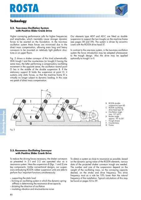
Fig. 2 shows a shaker conveyor of this kind schematically.<br />
With trough I and the countermass (or trough) II having the<br />
same mass, the latter performing a compensatory oscillating<br />
movement in the opposite sense, the oscillation neutral point<br />
O lies in the middle of the double suspension B. If the<br />
stationary support III holds the suspension at point O, it<br />
sustains only static forces, so that the machine frame III is<br />
virtually no longer subject to dynamic loading. In this case<br />
we speak of direct mass compensation.<br />
Our elements type AD-P and AD-C are fitted as doublesuspension<br />
to support the two troughs on the machine frame<br />
(see pages 58 and 59). The system is driven by eccentric<br />
crank with the <strong>ROSTA</strong> drive head ST.<br />
In contrast to the one-mass system, in the two-mass oscillation<br />
system the force introduction may be adapted wheresoever<br />
to the trough design. Also the drive may be applied<br />
optionally to trough I or II.<br />
<strong>Oscillating</strong> <strong>Mountings</strong><br />
Fig. 2<br />
B<br />
C<br />
α<br />
β<br />
I<br />
II<br />
III<br />
<strong>ROSTA</strong> double<br />
suspensions type AD<br />
<strong>ROSTA</strong> oscillating<br />
drive head type ST<br />
Oscillation angle<br />
max. 10° (±5°)<br />
Rocker angle<br />
approx. 10° to 30°<br />
Trough (mass)<br />
Countermass<br />
Frame<br />
2.3. Resonance <strong>Oscillating</strong> Conveyor<br />
with Positive Slider Crank Drive<br />
To reduce the driving forces necessary, the shaker conveyors<br />
as presented in 2.1 and 2.2 are operated also as a<br />
resonance system. Here the suspensions B (figs. 1 and 2) are<br />
key components. Unlike conventional designs, our suspensions<br />
embodying <strong>ROSTA</strong> rubber suspension units are able to<br />
perform four important functions simultaneously:<br />
– supporting the static load<br />
– forming an oscillating system in which the dynamic spring<br />
stiffness is determining the resonance drive-capacity<br />
– dictating the direction of oscillation<br />
– insulating vibration and structure-borne noise<br />
To obtain a system as close to resonance as possible, based<br />
on the dynamic spring value of the <strong>ROSTA</strong> elements, various<br />
data of the projected shaker conveyor trough are needed.<br />
The number and size of the suspensions depend on the<br />
weight of the oscillating mass, on the conveying capacity<br />
desired, on the stroke and drive frequency. This drive<br />
frequency must as a rule be 10% lower than the natural<br />
frequency of the installation. Typical calculations of this may<br />
be found on pages 53 to 59.<br />
46