ROSTA-Oscillating Mountings - ROSTA Inc.
ROSTA-Oscillating Mountings - ROSTA Inc.
ROSTA-Oscillating Mountings - ROSTA Inc.

Create successful ePaper yourself
Turn your PDF publications into a flip-book with our unique Google optimized e-Paper software.
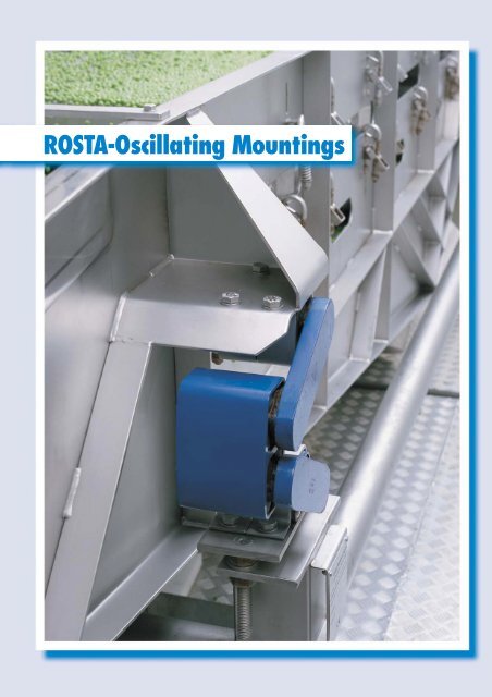
<strong>ROSTA</strong>-<strong>Oscillating</strong> <strong>Mountings</strong>
<strong>ROSTA</strong><br />
Technology<br />
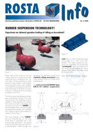
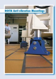
By virtue of their unique design, <strong>ROSTA</strong> rubber suspension<br />
units are eminently suited for guiding and linking a variety of<br />
vibrating and screening equipment. The jointed rubber<br />
spring assists the amplitudes to be transmitted to the actual<br />
oscillating equipment with a directional rotary rocking<br />
motion. Owing to the specific spring characteristic the element<br />
also acts as a virtually non-wearing spring accumulator,<br />
and is therefore predestined for linking applications in resonance<br />
vibration systems. Due to its unique design neither<br />
shear nor bending stresses occur at the support points –<br />
guaranteeing above-average life of the link rods.<br />
<strong>ROSTA</strong> supplies standardized link rods, rocker arms, spring<br />
supports and universal joints for all kinds of shaking,<br />
conveying and screening machines with positive or freely<br />
oscillating drive systems. <strong>ROSTA</strong> oscillating mountings have<br />
proved their worth for decades in vibrating, oscillating and<br />
rotating machinery in general process engineering.<br />
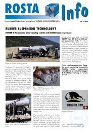
Superior Technology<br />
lateral mounting<br />
for suspension<br />
and support<br />
performs circular<br />
motions<br />
<strong>Oscillating</strong> <strong>Mountings</strong><br />
acts as spring<br />
accumulator<br />
maintenance-free<br />
oscillating bearing<br />
prestressed:<br />
therefore hard<br />
wearing<br />
compensates<br />
inaccuracies:<br />
optimal centering<br />
high insulating efficiency<br />
due to low natural<br />
frequency<br />
44<br />
high admissible oscillation<br />
frequency for maximum<br />
conveying performance<br />
elastic rocking motion
<strong>ROSTA</strong><br />
Technology<br />
1. <strong>Oscillating</strong> Conveyor Technology in General<br />
Technical development has led to a growing demand for the<br />
efficient yet gentle conveying of goods. One of the most<br />
economical answers to this need is the oscillating conveyor,<br />
which has major advantages over alternative systems:<br />
– simple design without parts requiring a lot<br />
of maintenance<br />
– extremely low wear in operation<br />
– screening and separating operations may be<br />
performed at the same time.<br />
<strong>Oscillating</strong> conveyors consist of trough-, box- or tube-shaped<br />
conveying units, the oscillation rockers and the oscillating<br />
exciter. While oscillating mass forces are set up which lead<br />
to two fundamental conveying modes. If the material<br />
“slides” forward, we speak of a chute conveyor, but if it is<br />
advanced in “short jumps” (microthrows) a shaker conveyor<br />
is involved.<br />
Chute conveyors have low frequencies (1–2 Hz) and large<br />
amplitudes (up to about 300 mm), and are specially suited<br />
for moving material in coarse lumps, as in mining.<br />
Shaker conveyors have high frequencies (up to 10 Hz) and<br />
small amplitudes (up to about 20 mm). They are suitable for<br />
moving almost all products, provided these do not cake or<br />
stick together, over short to medium distances, particularly<br />
hot and severe wearing materials.<br />
2. Different Oscillation Systems<br />
2.1. One-mass Oscillation System<br />
with Positive Slider Crank Drive<br />
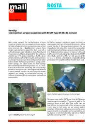
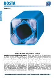
This simplest oscillating conveyor design (fig. 1) is the most<br />
economical and consists of the oscillating trough (I), the<br />
rocker suspension (B), the drive (CD) and base frame (III).<br />
Because there is no mass compensation here, it is employed<br />
primarily where dynamic forces exerted to the foundation are<br />
small, i.e. where the trough acceleration does not exceed<br />
1.6 g. In any case the conveyor must be installed on a solid<br />
substructure (in a basement, on a heavy base frame or solid<br />
floor).<br />
The direction of conveying is geared by the rocker suspension<br />
(B), so that we speak of unidirectional conveyors. As<br />
rocker suspension we recommend our types AU, AS-P or AS-<br />
C (see pages 52 to 57).<br />
The system is advantageously driven by a crank mechanism,<br />
in which our oscillating drive head (C) is used as a positive,<br />
elastic torsion bearing.<br />
With this crank drive, low frequencies with long throws are<br />
achieved in simple fashion, as are essential for the design of<br />
long shakers.<br />
The ratio R : L must be as low as possible in order to obtain<br />
harmonic excitation. The amplitude corresponds to the crank<br />
radius R, while the throw is 2 R. The frequencies of such<br />
slider crank oscillating troughs lie between 5 and 10 Hz,<br />
with throws between 10 and 40 mm. The movement of<br />
material can be controlled during operation by variablespeed<br />
motors or drives. In one-mass oscillation systems the<br />
force introduction i.e. the main direction of oscillation X must<br />
be directed ahead of the centre of gravity S (fig. 1).<br />
The crank shaft has to be driven by belts, in order to<br />
compensate the shocks at stroke ends!<br />
<strong>Oscillating</strong> <strong>Mountings</strong><br />
Fig. 1<br />
B <strong>ROSTA</strong> oscillating mountings<br />
type AU or AS<br />
C <strong>ROSTA</strong> oscillating drive head type ST<br />
D Connecting rod<br />
L Sliding crank length<br />
R Sliding crank radius (amplitude)<br />
S Center of gravity of trough (mass)<br />
X Main oscillation direction<br />
α Oscillation angle max. 10° (±5°)<br />
β Rocker angle approx. 10° to 30°<br />
I Trough (mass)<br />
III Frame<br />
45
<strong>ROSTA</strong><br />
Technology<br />
2.2. Two-mass Oscillation System<br />
with Positive Slider Crank Drive<br />
Higher conveying performance calls for higher frequencies<br />
and amplitudes, which inevitably cause stronger dynamic<br />
forces to be exerted on the foundation. In the two-mass<br />
oscillation system these forces are minimized due to the<br />
direct mass compensation, allowing even long and heavy<br />
conveyors to be mounted on relatively light platform structures<br />
or on upper floors.<br />
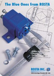
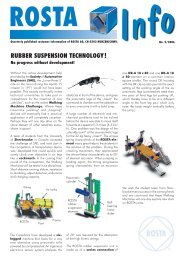
Fig. 2 shows a shaker conveyor of this kind schematically.<br />
With trough I and the countermass (or trough) II having the<br />
same mass, the latter performing a compensatory oscillating<br />
movement in the opposite sense, the oscillation neutral point<br />
O lies in the middle of the double suspension B. If the<br />
stationary support III holds the suspension at point O, it<br />
sustains only static forces, so that the machine frame III is<br />
virtually no longer subject to dynamic loading. In this case<br />
we speak of direct mass compensation.<br />
Our elements type AD-P and AD-C are fitted as doublesuspension<br />
to support the two troughs on the machine frame<br />
(see pages 58 and 59). The system is driven by eccentric<br />
crank with the <strong>ROSTA</strong> drive head ST.<br />
In contrast to the one-mass system, in the two-mass oscillation<br />
system the force introduction may be adapted wheresoever<br />
to the trough design. Also the drive may be applied<br />
optionally to trough I or II.<br />
<strong>Oscillating</strong> <strong>Mountings</strong><br />
Fig. 2<br />
B<br />
C<br />
α<br />
β<br />
I<br />
II<br />
III<br />
<strong>ROSTA</strong> double<br />
suspensions type AD<br />
<strong>ROSTA</strong> oscillating<br />
drive head type ST<br />
Oscillation angle<br />
max. 10° (±5°)<br />
Rocker angle<br />
approx. 10° to 30°<br />
Trough (mass)<br />
Countermass<br />
Frame<br />
2.3. Resonance <strong>Oscillating</strong> Conveyor<br />
with Positive Slider Crank Drive<br />
To reduce the driving forces necessary, the shaker conveyors<br />
as presented in 2.1 and 2.2 are operated also as a<br />
resonance system. Here the suspensions B (figs. 1 and 2) are<br />
key components. Unlike conventional designs, our suspensions<br />
embodying <strong>ROSTA</strong> rubber suspension units are able to<br />
perform four important functions simultaneously:<br />
– supporting the static load<br />
– forming an oscillating system in which the dynamic spring<br />
stiffness is determining the resonance drive-capacity<br />
– dictating the direction of oscillation<br />
– insulating vibration and structure-borne noise<br />
To obtain a system as close to resonance as possible, based<br />
on the dynamic spring value of the <strong>ROSTA</strong> elements, various<br />
data of the projected shaker conveyor trough are needed.<br />
The number and size of the suspensions depend on the<br />
weight of the oscillating mass, on the conveying capacity<br />
desired, on the stroke and drive frequency. This drive<br />
frequency must as a rule be 10% lower than the natural<br />
frequency of the installation. Typical calculations of this may<br />
be found on pages 53 to 59.<br />
46
<strong>ROSTA</strong><br />
Technology<br />
3. Terminology and Calculation<br />
3.1. Terminology<br />
Symbol Unit term<br />
a m · s – 2 Acceleration<br />
A mm Distances between centres<br />
c d N/mm Dynamic spring value<br />
c t N/mm Total spring value<br />
f Hz Frequency<br />
f e Hz Natural frequency<br />
f err Hz Excitation frequency<br />
F N Force<br />
g 9.81m/s 2 Gravitational acceleration<br />
K<br />
machine acc.<br />
grav. acc.<br />
<strong>Oscillating</strong> machine factor<br />
m kg Mass<br />
M Nm Torque<br />
n e min –1 Revolutions per minute<br />
Symbol Unit Term<br />
R mm Crank radius<br />
S – Center of gravity<br />
sw mm Throw<br />
t s Time<br />
v m/s Velocity<br />
v th m/s Theoretical velocity<br />
Z – Quantity (number)<br />
W % Isolation efficiency<br />
α ° Oscillation angle<br />
β ° Rocker angle<br />
Γ – Throw factor<br />
ω rad/s Rotational frequency<br />
3.2. Calculation<br />
Formulas for calculating oscillating machines<br />
by the known equation from oscillation theory<br />
Total spring value<br />
c t = m · ( 2π · n e ) 2 · 10 – 3<br />
60<br />
[N/mm]<br />
<strong>Oscillating</strong> <strong>Mountings</strong><br />
Natural frequency<br />
f e = 1 ·<br />
√ c t · 1000<br />
2π m<br />
[Hz]<br />
Number of rocker suspensions for resonance operation<br />
z = c t<br />
c d<br />
[piece]<br />
<strong>Oscillating</strong> machine factor<br />
Ratio of machine acceleration<br />
to gravitational acceleration<br />
K = (2π 60 · n e ) 2 · R<br />
9810<br />
[–]<br />
Throw factor<br />
Γ = K · sin β [–]<br />
Accelerative force<br />
F = K · m · g<br />
[N]<br />
Driving power<br />
(approximation)<br />
P ≈ R · K · m · g · n e<br />
9550 · 1000 ·<br />
√ 2<br />
[kW]<br />
47
<strong>ROSTA</strong><br />
Technology<br />
4. Free Oscillation Systems<br />
Freely oscillating one-mass systems (figs. 4 to 6) are supported<br />
with <strong>ROSTA</strong> oscillating mountings type AB. In this<br />
case the angle at which the excitation force is applied<br />
determines the direction of oscillation. Thanks to the low<br />
frequency support, free oscillators impose only very small<br />
dynamic loads on the foundation. Because the dynamic<br />
flexural rigidity decreases as the square of the length, however,<br />
only certain conveyor lengths can be executed, otherwise<br />
oscillation nodes occur which obstruct conveying.<br />
Suitable mounting of the drive ensures that the revolving<br />
unbalance is utilized only by the components in the actual<br />
direction of conveying. For example, two unbalanced masses<br />
counterrotating synchronously set up the necessary excitation<br />
force in that the flow components in the direction of the line<br />
joining the two centres of rotation cancel each other out,<br />
while those at right angles add up to give the harmonic excitation<br />
force. To avoid the unbalanced masses assuming excessive<br />
magnitude, the excitation frequency is 15 to 50 Hz.<br />
Free-oscillating conveyors are driven by non-positive inertia<br />
drives exploiting the action of rotating unbalanced masses.<br />
4.1. Drive with one Unbalanced Motor<br />
This alternative (fig. 4) is used mainly on rotary oscillators,<br />
which are used mostly for inclined screen constructions. If<br />
an unbalanced motor is flanged onto a screening unit, the<br />
system performs slightly elliptical motions whose shape<br />
depends on the distance between the two centres of gravity<br />
S (screen) and S 1 (unbalanced motor), and on the screen<br />
design.<br />
feeding direction<br />
<strong>Oscillating</strong> <strong>Mountings</strong><br />
4.2. Drive with one Unbalanced Motor<br />
and Oscillation Bearing<br />
Linear oscillators with unbalanced motor on an oscillating<br />
bearing (fig. 5) are employed for screens and short, light<br />
conveyors.<br />
If an unbalanced motor is flanged onto a machine through<br />
on an oscillating bearing E (e.g. DK-A with bracket BK,<br />
pages 21 and 26) so that the centres of the motor and<br />
oscillating bearing and the centre of gravity of the screen lie<br />
B <strong>ROSTA</strong> oscillating mountings<br />
type AB<br />
E Centre of gravity of screen<br />
S Centre of gravity<br />
of unbalanced motor<br />
I Screen<br />
III Frame<br />
in a straight line, then approximately linear oscillations will<br />
be generated. Through the oscillating bearing the centrifugal<br />
forces are transmitted almost entirely to the screen or trough,<br />
where as the transverse forces remain ineffective. The<br />
oscillating bearing drive may be used only with smaller<br />
machines.<br />
feeding direction<br />
B <strong>ROSTA</strong> oscillating mountings<br />
type AB<br />
E <strong>ROSTA</strong> rubber suspension units<br />
type DK-A with clamp BK<br />
S Centre of gravity of screen<br />
I Screen<br />
III Frame<br />
48
<strong>ROSTA</strong><br />
Technology<br />
4.3. Drive with two Unbalanced Motors<br />
If two unbalanced motors are used with a conveyor or screen<br />
(fig. 6), it must be borne in mind that they counterrotate and<br />
are joined absolutely rigid, so that they synchronize at once<br />
when switched on, setting-up linear oscillations.<br />
feeding direction<br />
B <strong>ROSTA</strong> oscillating mountings<br />
type AB<br />
S Centre of gravity<br />
of trough/screen<br />
I Trough/screen<br />
III Frame<br />
4.4. Calculation for a Linear Oscillator<br />
with two Unbalanced Motors<br />
The proper size of the oscillation mountings type AB is<br />
determined as follows:<br />
<strong>Oscillating</strong> weight (conveyor with 2 motors + proportion of<br />
material being moved) divided by number of support points<br />
(the individual points must be loaded approximately equally).<br />
Formulas for the principal variables of a free oscillator:<br />
At least 6 supports, if not more, are needed for a linear<br />
oscillator. The excitation frequency may be neglected,<br />
because according to experience the amplitudes do not<br />
exceed 15 mm, so that the oscillation angles are relatively<br />
small. The natural frequency of the AB must be at least<br />
3 times lower than its excitation frequency.<br />
Nomogram: conveying speed for free oscillating screens<br />
From the intersection of the coordinates amplitude = 4 mm<br />
and motor speed n = 1460 rpm, with acceleration around<br />
5 g the conveying speed emerges as 25 cm/sec.<br />
<strong>Oscillating</strong> <strong>Mountings</strong><br />
<strong>Oscillating</strong> amplitude<br />
sw = working torque in kgcm · 10 =<br />
total weight in kg<br />
mm<br />
<strong>Oscillating</strong> machine factor<br />
K = (2π 60 · n e<br />
) 2 · R = [–]<br />
Insulation efficiency<br />
9810<br />
f e<br />
( f 2<br />
err ) –1<br />
f e<br />
W = (f err<br />
) 2 –2<br />
· 100 = %<br />
Theoretical conveying speed v in cm/sec.<br />
acceleration<br />
<strong>Oscillating</strong> amplitude sw in mm = double the amplitude<br />
49
<strong>ROSTA</strong><br />
Product Range<br />
<strong>ROSTA</strong> <strong>Oscillating</strong> Mounting Type AU<br />
Pages 52 and 53<br />
<strong>ROSTA</strong> oscillating mountings type AU are maintenance-free elastic joints for suspending or<br />
supporting conveying troughs, screens, sorters and all devices excited by eccentric drives<br />
or unbalanced motors with directed oscillations. They are primarily used for installations<br />
with an effective distance between the single units (rocker length A) in special designed<br />
small serie shakers and troughs, i.e. in cases the spacing of the AS type does not fit the<br />
construction.<br />
These AU elements are mounted on the trough by means of fixing flanges. The housings are<br />
available with either right- or left-hand threads. They are joined together by means of a<br />
threaded rod which must be provided by the customer.<br />
The rocker housings are made of die-cast aluminium, AU 50 and 60 types are made of<br />
spheroidal graphite cast iron. All cores have fixing plates made of steel.<br />
<strong>ROSTA</strong> Rocker Suspension Type AS-P/AS-C<br />
Pages 56 and 57<br />
The <strong>ROSTA</strong> rocker suspension units type AS-P and AS-C are maintenance-free elastic guide<br />
arms used for the same purposes as the oscillating mountings type AU. This low-cost model<br />
is a suitable for fixed distances between the two bearings (rocker length A).<br />
The AS-P types are mounted on the trough or the machine frame by means of fixing flanges.<br />
The AS-C types are designed to be frictionally engaged to the machine frame. The central<br />
mounting allows an easy adjustment of the rocking angle.<br />
The housings and the inner square sections are made of welded steel. The core of the<br />
AS-P type is equipped with fixing plates which are similar to the ones of the AU type. The<br />
inner square section of the AS-C type is made of aluminium profile.<br />
<strong>Oscillating</strong> <strong>Mountings</strong><br />
<strong>ROSTA</strong> Double Suspension Type AD-P/AD-C<br />
Pages 58 and 59<br />
The <strong>ROSTA</strong> double suspension units type AD-P/AD-C are used for suspending and<br />
supporting two-mass shaker systems. The centre point, for frame fixation, is in the middle of<br />
the double rocker arm.<br />
The AD-P suspension units are mounted by means of fixing flanges. The AD-C model is<br />
designed to be frictionally engaged in the same way as the AS-C type.<br />
The housings and the inner square sections are made of welded steel. The core of the AD-P<br />
type is equipped with fixing plates constructed analogously to the AU type. The inner<br />
square section of the AS-C type are made of aluminium profile.<br />
<strong>ROSTA</strong> <strong>Oscillating</strong> Mounting Type AB<br />
Pages 60 and 61<br />
The <strong>ROSTA</strong> oscillating mountings type AB are maintenance-free elastic joints for<br />
suspending or supporting vibrating screens or shakers driven by different exciter systems.<br />
They guide the centrifugal forces in the conveying direction and optimally keep the<br />
oscillating part in linear direction. The extremely low resonant frequency guarantees best<br />
vibration isolation to substructure and basement. The AB mountings considerably reduce<br />
the uncontrolled tumbling of the spring supports by passing the natural frequency.<br />
The AB oscillating units are mounted to the basement or the screen body by means of<br />
fixing clamps (except type AB 50), which allows to adjust these units also laterally when<br />
installing them.<br />
The double housings of size 15 to 45 are made of light alloy; the housings of sizes 50<br />
are made of spheriodal graphite cast iron.<br />
50
<strong>ROSTA</strong><br />
Product Range<br />
<strong>ROSTA</strong> <strong>Oscillating</strong> Drive Head Type ST<br />
Page 62<br />
<strong>ROSTA</strong> oscillating drive heads type ST are flexible joints transmitting the acceleration forces<br />
from eccentric drive to the oscillating machine part – free of play, silently, reliably and<br />
without requiring maintenance. The common maintenance problems which are<br />
characteristic of these drive components are thus eliminated.<br />
The inner square section (core) and the trough are joined together by a so-called “fork”.<br />
The outer housing is screwed to the slider crank rod and locked. Right- or left-hand threads<br />
are available, which allows the crank length to be adjusted easily.<br />
The drive heads up to type ST 45 have got an aluminium housing and core; type ST 50 has<br />
a housing made of SC iron and an aluminium core; ST 60 and ST 80 have an SC iron<br />
housing and a steel core.<br />
<strong>ROSTA</strong> Rubber Suspension Unit Type DO-A<br />
used as elastic drive head or spring accumulator<br />
Pages 63, 64 and 65<br />
The <strong>ROSTA</strong> rubber suspension unit type DO-A for resonance shaker conveyors is used<br />
as an elastic oscillating drive head and/or as spring accumulator in natural frequency<br />
shakers. Its high dynamic stiffness, best reliability and maintenance-free functioning are the<br />
most important features of this component. The same element DO-A is used especially in<br />
general mechanical engineering (see page 23).<br />
Types with sizes up to 45 have got aluminium housings. Types 50 have got SC iron<br />
housings; the inner square sections are made of light alloy with 4 holes allowing to fix them<br />
to the eccentric rod or shaker conveyor by means of a fork bracket.<br />
<strong>ROSTA</strong> Universal Joint Type AK<br />
Pages 66 and 67<br />
The <strong>ROSTA</strong> universal joints type AK are maintenance-free elastic joints which can be moved<br />
in any direction. They are used as universal joint supports for mounting or suspending<br />
gyratory screens, screening tables, tumbling oscillators, sorters and screening machines<br />
positively driven by eccentrics or freely oscillating with unbalanced drive.<br />
The types AK 27, AK 38, AK 45, AK 50 and AK 100 have got housings made of SC iron,<br />
all the other sizes are made of welded steel structures. The types AK 15 to AK 50 have got<br />
aluminium square sections, the other sizes have steel cores.<br />
<strong>ROSTA</strong> <strong>Oscillating</strong> Mounting Type AV<br />
Pages 68 and 69<br />
<strong>Oscillating</strong> <strong>Mountings</strong><br />
The <strong>ROSTA</strong> oscillating mountings type AV are maintenance-free elastic joints designed for<br />
guiding circular motions of hanging screens such as gyratory sifters and screens in flour<br />
mills, chemical processing plants and paper mills.<br />
The rubber inserts of these oscillating mountings are larger than the ones of the other<br />
<strong>ROSTA</strong> elements. Therefore they intensively absorb the vibrations of the hanging sifters and<br />
better protect the building structures and ceilings.<br />
All these mounting types have got housings made of cast aluminium; only type AV 50 has<br />
got an SC-cast-iron housing. The cores are all made of aluminium profiles.<br />
<strong>ROSTA</strong> <strong>Oscillating</strong> Mounting Type AR<br />
Pages 54 and 55<br />
The <strong>ROSTA</strong> oscillating mountings type AR are maintenance-free elastic joints used for the<br />
same purposes as our other oscillating mounting types AU, AS or AD. The distance<br />
between the centres can be freely chosen. The commercial circular tube (connection<br />
between the two elements) must be supplied by the customer. The inner square profile is<br />
frictionally engaged to the machine frame, analogously to type AS-C and AD-C.<br />
The housing of mounting type AR is made of cast aluminium, the core is made of aluminium<br />
profile.<br />
51
<strong>ROSTA</strong><br />
<strong>Oscillating</strong> Mounting<br />
Type AU<br />
G<br />
Fixing flange<br />
AU 60<br />
Weight<br />
Art. No Type G n e Md d A B C D E H J K L M N O in kg<br />
<strong>Oscillating</strong> <strong>Mountings</strong><br />
07011001 AU15 100 1200 0.44 50 4 29,5 20 28 50 70 25 40 M10 7 33 0.19<br />
07021001 AU15L 100 1200 0.44 50 4 29,5 20 28 50 70 25 40 M10L 7 33 0.19<br />
07011002 AU18 200 1200 1.32 62 5 31.5 22 34 60 85 35 45 M12 9.5 39 0.34<br />
07021002 AU18L 200 1200 1.32 62 5 31.5 22 34 60 85 35 45 M12L 9.5 39 0.34<br />
07011003 AU27 400 800 2.60 73 5 40.5 28 40 80 110 45 60 M16 11.5 54 0.65<br />
07021003 AU27L 400 800 2.60 73 5 40.5 28 40 80 110 45 60 M16L 11.5 54 0.65<br />
07011004 AU38 800 800 6.70 95 6 53,5 42 52 100 140 60 80 M20 14 74 1.55<br />
07021004 AU38L 800 800 6.70 95 6 53,5 42 52 100 140 60 80 M20L 14 74 1.55<br />
07011005 AU45 1600 800 11.60 120 8 67,5 48 66 130 180 70 100 M24 18 89 2.55<br />
07021005 AU45L 1600 800 11.60 120 8 67,5 48 66 130 180 70 100 M24L 18 89 2.55<br />
07011006 AU50 2500 600 20.40 145 10 70,5 60 80 140 190 80 105 M36 18 92 6.70<br />
07021006 AU50L 2500 600 20.40 145 10 70,5 60 80 140 190 80 105 M36L 18 92 6.70<br />
07011007 AU60 5000 400 46.60 233 15 85,5 80 128 180 230 120 130 M42 18 116 15.70<br />
07021007 AU60L 5000 400 46.60 233 15 85,5 80 128 180 230 120 130 M42L 18 116 15.70<br />
G = max. loading in N per unit or rocker suspension<br />
ne = max. frequency in min –1 at
<strong>ROSTA</strong><br />
<strong>Oscillating</strong> Mounting<br />
Type AU<br />
To calculate the dynamic spring value of an oscillating mounting, for<br />
example 2 AU 27, operating close to resonance.<br />
Given:<br />
Dynamic torque. Md d<br />
Mounting with distance A between centres<br />
= 2.6 Nm/°<br />
= 200 mm<br />
Wanted:<br />
Dynamic spring value c d<br />
c d = Md d · 360 · 1000 2.6 · 360 · 1000<br />
=<br />
A 2 · π<br />
200 2 · π<br />
= 7.4 N/mm<br />
Typical Calculation<br />
Given:<br />
Weight of trough<br />
Material on trough<br />
of this 20% coupling effect<br />
Total weight of oscillating mass m<br />
(trough and coupling effect)<br />
Eccentric radius R<br />
<strong>Oscillating</strong> machine factor K = (2π 60 · n e<br />
) 2 · R<br />
= 1.6<br />
9810<br />
60<br />
= 200 kg<br />
= 50 kg<br />
= 10 kg<br />
= 210 kg<br />
= 14 mm<br />
Speed n e = 320 min –1<br />
Total spring value c t = m · ( 2π · n e) 2 · 10 –3<br />
= 235.8 N/mm<br />
Wanted:<br />
Number of oscillating mountings each comprising 2 elements type AU 27<br />
a) in resonance operation<br />
Here the total spring value of the mountings must be about 10%<br />
above the total spring value c t of the installation. From this follows:<br />
Spring value c d of an oscillating mounting consisting of two AU 27<br />
spaced at 200 mm = 7.4 N/mm.<br />
c t<br />
Number of mountings = =<br />
0.9 · c d<br />
235.8<br />
= 35.4 pieces<br />
0.9 · 7.4<br />
Selected: 36 mountings each comprising two AU 27 = 72 x AU 27<br />
b) without resonance operation<br />
Here the total weight G must be taken up by the total number of oscillating<br />
mountings. The admissible loading of one mounting comprising<br />
two AU 27 is 400 N.<br />
Number of mountings = m · g = 210 · 9.81 = 5.15 pieces<br />
400 400<br />
Selected: 6 oscillating mountings each comprising<br />
two AU 27 = 12 x AU 27<br />
<strong>Oscillating</strong> <strong>Mountings</strong><br />
Connecting Rod<br />
M<br />
LH thread<br />
Screwed-in length 1.5 - 2M<br />
A<br />
The connecting rod is provided by the customer, preferably with left/<br />
right-hand thread. Together with the associated oscillating mountings AU<br />
the distance between elements A can then be levelled steplessly. Lower<br />
costs may be attained, though at the price of rougher levelling, by using<br />
commercial rods with right-head thread only. In any case the<br />
appropriate screwed-in length must be observed.<br />
RH thread<br />
53
<strong>ROSTA</strong><br />
<strong>Oscillating</strong> Mounting<br />
Type AR<br />
N<br />
M<br />
A<br />
B<br />
O<br />
L<br />
L1<br />
<strong>Oscillating</strong> <strong>Mountings</strong><br />
Load G in N Dimensions in mm Weight<br />
K=2 K=3 K=4 n e Md d A B C H L L1 M N O S<br />
+0.2<br />
+0.5<br />
+0.3<br />
0<br />
–0.3<br />
+0.2 +0.5<br />
0<br />
+0.2<br />
–0.3<br />
<strong>ROSTA</strong><br />
<strong>Oscillating</strong> Mounting<br />
Type AR<br />
Double Drive Head<br />
20–30°<br />
Förderrichtung<br />
conveying direction<br />
A1 A2<br />
Förderrichtung<br />
conveying direction<br />
<strong>ROSTA</strong> oscillating mountings type AR in double rocker configuration: These elements are mounted in the same way as<br />
the single rocker arms. However, the material thickness of the round connection tube must be adapted according to the final<br />
center distances (see table on bottom left of this page). The double rocker arm allows easy installation in high-speed two-mass<br />
shaker conveyors with direct balancing. The counterweight can be used as additional conveyor trough. The material flows in<br />
the same direction, both on the trough and the counterweight.<br />
Bidirectional Drive Head<br />
20–30°<br />
Förderrichtung<br />
conveying direction<br />
Förderrichtung<br />
conveying direction<br />
A1 A2<br />
<strong>Oscillating</strong> <strong>Mountings</strong><br />
<strong>ROSTA</strong> oscillating mountings type AR in boomerang configuration for bidirectional conveying. The double rocker is<br />
mounted vertically, the middle element is rotated by 180°. The angles of the double rocker go in opposite direction, causing<br />
the material on the counterweight to move in opposite direction, too. The bidirectional conveying allows an easier processing<br />
of the bulk material, but still guarantees a perfect balancing of masses for high-speed oscillating conveyors.<br />
Dynamic Spring Value<br />
The dynamic spring value c d<br />
of an oscillation unit consisting<br />
of 3 elements, type AR, is calculated as following:<br />
( )<br />
3 · 360 · Md<br />
c d = d · 1000 1 1<br />
· + = [N/mm]<br />
4 · π<br />
A1 2 A2 2<br />
c d = dynamic spring value in N/mm with torsion
<strong>ROSTA</strong><br />
Rocker Suspension<br />
Type AS-P<br />
G<br />
Type AS-PV<br />
B1<br />
A<br />
ØK<br />
ØK<br />
H<br />
F<br />
D<br />
C<br />
E<br />
B<br />
Type AS-PV with one offset flange<br />
Weight<br />
Art. No Type G n e sw c d A B C D E F H ØK in kg<br />
07 081 001 AS-P 15 100 1200 17 5 100 50 4 50 70 7 25 18 0.54<br />
07 081 002 AS-P 18 200 1200 21 10 120 62 5 60 85 9.5 35 24 0.81<br />
07 081 003 AS-P 27 400 800 28 12 160 73 5 80 110 11.5 45 34 1.79<br />
07 081 004 AS-P 38 800 800 35 19 200 95 6 100 140 14 60 40 3.57<br />
07 081 005 AS-P 45 1600 800 35 33 200 120 8 130 180 18 70 45 5.52<br />
07 081 006 AS-P 50 2500 600 44 38 250 145 10 140 190 18 80 60 8.27<br />
Weight<br />
Art. No Type G n e sw c d A B1 C D E F H ØK in kg<br />
<strong>Oscillating</strong> <strong>Mountings</strong><br />
07 091 001 AS-PV 15 100 1200 17 5 100 56 4 50 70 7 25 18 0.54<br />
07 091 002 AS-PV 18 200 1200 21 10 120 68 5 60 85 9.5 35 24 0.81<br />
07 091 003 AS-PV 27 400 800 28 12 160 80 5 80 110 11.5 45 34 1.79<br />
07 091 004 AS-PV 38 800 800 35 19 200 104 6 100 140 14 60 40 3.57<br />
07 091 005 AS-PV 45 1600 800 35 33 200 132 8 130 180 18 70 45 5.52<br />
07 091 006 AS-PV 50 2500 600 44 38 250 160 10 140 190 18 80 60 8.27<br />
G = max. loading in N per suspension<br />
n e = max. frequency in min –1 at
<strong>ROSTA</strong><br />
Rocker Suspension<br />
Type AS-C<br />
G<br />
A<br />
ØK<br />
ØK<br />
E<br />
C<br />
B<br />
D<br />
Weight<br />
Art. No Type G n e sw c d A B C D E ØF in kg<br />
+0.4<br />
07 071 001 AS-C 15 100 1200 17 5 100 40 2.5 45 10+0.2<br />
18 0.38<br />
0<br />
07 071 002 AS-C 18 200 1200 21 10 120 50 2.5 55 13+0.2<br />
24 0.56<br />
+0.5<br />
07 071 003 AS-C 27 400 800 28 12 160 60 2.5 65 16+0.3<br />
34 1.31<br />
+0.5<br />
07 071 004 AS-C 38 800 800 35 19 200 80 5 90 20+0.2<br />
40 2.60<br />
+0.5<br />
07 071 005 AS-C 45 1600 800 35 33 200 100 5 110 24+0.2<br />
45 3.94<br />
+0.5<br />
07 071 006 AS-C 50 2500 600 44 38 250 120 5 130 30+0.2<br />
60 6.05<br />
G = max. loading in N per suspension<br />
n e = max. frequency in min –1 at
<strong>ROSTA</strong><br />
Double Suspension<br />
Type AD-P<br />
Type AD-PV<br />
Type AD-PV with offset flanges<br />
G<br />
Weight<br />
Art. No Type K=2 K=3 K=4 n e sw c d A B C D E F H in kg<br />
07111001 AD-P18 150 120 100 640 17 22 100 62 5 60 85 9.5 35 1.21<br />
07111002 AD-P27 300 240 200 590 21 32 120 73 5 80 110 11.5 45 2.55<br />
07111003 AD-P38 600 500 400 510 28 45 160 95 6 100 140 14,5 60 5.54<br />
07111004 AD-P45 1200 1000 800 450 35 50 200 120 8 130 180 18,5 70 8.51<br />
07111005 AD-P50 1800 1500 1200 420 44 55 250 145 10 140 190 18,5 80 12.90<br />
<strong>Oscillating</strong> <strong>Mountings</strong><br />
G<br />
Weight<br />
Art. No Type K=2 K=3 K=4 n e sw c d A B 1 C D E F H in kg<br />
07121001 AD-PV18 150 120 100 640 17 22 100 68 5 60 85 9.5 35 1.21<br />
07121002 AD-PV27 300 240 200 590 21 32 120 80 5 80 110 11.5 45 2.55<br />
07121003 AD-PV38 600 500 400 510 28 45 160 104 6 100 140 14,5 60 5.54<br />
07121004 AD-PV45 1200 1000 800 450 35 50 200 132 8 130 180 18,5 70 8.51<br />
07121005 AD-PV50 1800 1500 1200 420 44 55 250 160 10 140 190 18,5 80 12.90<br />
G = max. loading in N per suspension<br />
K = oscillating machine factor<br />
n e = max. frequency in min–1 at
<strong>ROSTA</strong><br />
Double Suspension<br />
Type AD-C<br />
Weight<br />
Art. No Type K=2 K=3 K=4 n e sw c d A B C D E in kg<br />
0<br />
07101001 AD-C18 150 120 100 640 17 22 100 50 2.5 55 13–0.2<br />
0.84<br />
+0.5<br />
07101002 AD-C27 300 240 200 590 21 32 120 60 2.5 65 16+0.3<br />
1.84<br />
+0.5<br />
07101003 AD-C38 600 500 400 510 28 45 160 80 5,5 90 20+0.2<br />
4.09<br />
+0.5<br />
07101004 AD-C45 1200 1000 800 450 35 50 200 100 5,5 110 24+0.2<br />
6.08<br />
G = max. loading in N per suspension<br />
K = oscillating machine factor<br />
n e = max. frequency in min–1 at
<strong>ROSTA</strong><br />
<strong>Oscillating</strong> Mounting<br />
Type AB<br />
AB15 – 45<br />
AB50<br />
C<br />
C<br />
A<br />
A<br />
17 x 27<br />
AB50-2<br />
D<br />
H<br />
B<br />
E<br />
F<br />
K<br />
I<br />
L<br />
M<br />
H<br />
B<br />
E<br />
F<br />
K<br />
60<br />
L<br />
M<br />
K<br />
70 70<br />
L<br />
M<br />
A A B B<br />
un max. unloaded<br />
C loaded C ØD E F H I K L M in<br />
max.<br />
Weight<br />
Art. No Type Load in N loaded<br />
A loaded<br />
B kg<br />
07 051 001 AB 15 1300 – 12160 165 120 70 89 80 7 50 65 2 25 10 40 52 0.67<br />
07 051 002 AB 18 1120 – 0300 203 150 87 107 100 9 60 80 2.5 30 14 50 67 1.35<br />
07 051 003 AB 27 1250 – 3800 230 170 94 114 100 11 80 105 3 35 17 60 80 2.65<br />
07 051 004 AB 38 2600 – 1600 295 225 120 144 125 13 100 125 4 40 21 80 104 6.20<br />
07 051 005 AB 45 1200 – 3000 340 260 137 164 140 13 115 145 5 45 28 100 132 10.60<br />
07 051 006 AB 50 2500 – 16000 380 280 150 180 150 – 130 170 12 – 35 120 160 19.12<br />
07 051 050 AB 50-2 4200 – 10000 380 280 150 180 150 – 130 170 12 – 40 200 245 30.00<br />
c d AB 15 AB 18 AB 27 AB 38 AB 45 AB 50 AB 50-2<br />
<strong>Oscillating</strong> <strong>Mountings</strong><br />
vertical<br />
horizontal<br />
10 18 40 60 100 190 320<br />
6 14 25 30 50 85 140<br />
c d = dynamic spring value in N/mm, in nominal load range at n e = 960 rpm, sw 8 mm<br />
Load on compression in N<br />
Load capacity<br />
f Natural frequency in HZ<br />
Load on compression in N<br />
Load capacity<br />
f Natural frequency in HZ<br />
Deflection in mm<br />
Deflection in mm<br />
Quantity<br />
Art. No Type AB Type per unit<br />
Brackets BR<br />
For the fixation of the oscillating elements type AB 15 to AB 45 it requires<br />
clamps, which are not included in the “AB” article no. They have<br />
to be ordered according the bystanding list.<br />
01 500 002 BR 15 AB 15 2<br />
01 500 003 BR 18 AB 18 2<br />
01 500 004 BR 27 AB 27 2<br />
01 500 005 BR 38 AB 38 4<br />
01 500 006 BR 45 AB 45 4<br />
60
<strong>ROSTA</strong><br />
<strong>Oscillating</strong> Mounting<br />
Type AB<br />
Typical Calculation<br />
The size and number of the oscillating mountings type AB are calculated<br />
as follows: oscillating weight (device consisting of drive units and the<br />
material conveyed) divided by the number of supports. The excitation<br />
frequency can be ignored as the amplitudes do not exceed 15 mm. The<br />
oscillating angle may thus be neglected. The excitation frequency must<br />
be at least 3 times higher than the natural frequency of the AB oscillating<br />
mountings.<br />
Given:<br />
Weight of the empty trough with drive unit<br />
Material on trough<br />
of which 20% for coupling effect<br />
Total weight of oscillating mass m<br />
(trough, driving unit and coupling)<br />
6 support points<br />
= 680 kg<br />
= 50 kg<br />
= 10 kg<br />
= 690 kg<br />
Wanted:<br />
Loading per support = m · g = 690 · 9.81 = 1128.15 N<br />
6 6<br />
Selected: 6 units of type AB 38<br />
See formulas on page 49 for calculating the amplitudes, machine factors<br />
and insulation efficiency.<br />
Installation Guidelines<br />
The <strong>ROSTA</strong> oscillating elements type AB have to be chosen according to<br />
the weight of the oscillating mass (see page 60). They must be installed<br />
between the screen structure and the basement, according to the<br />
position of the centre of gravity (see following example). The upper arm<br />
is the rocking arm of the oscillating unit. All elements should be mounted<br />
in the same direction, the upper arms being inclined in the direction of<br />
the material flow (see following example). This way, the upper arms of<br />
the drive heads support the linear motion of the screening machine. The<br />
lower arm acts as a vibration damper only partly executing the<br />
movement of the machine. However, due to its considerable spring<br />
deflection the lower arm guarantees a very low natural frequency of the<br />
screen support. In order to assure an optimal conveying of the<br />
material it is important to fix the AB element axis at right<br />
angles to the conveying direction (allowance: ±1°). (Fig. 1,<br />
section A).<br />
conveying direction<br />
Drive Options<br />
A. Circular Oscillator with one unbalanced Motor<br />
The unbalanced motor causes the device to perform elliptical oscillating<br />
movements of which the form is given by the distance between the<br />
centres of gravity of the motor and the screen device and the shape of<br />
the latter. Circular vibrating screens are mounted (inclined) according to<br />
the their function (see fig. 1).<br />
α 35°<br />
Fig. 1<br />
conveying direction<br />
S<br />
A<br />
<strong>Oscillating</strong> <strong>Mountings</strong><br />
B. Linear Oscillators with two unbalanced Motors<br />
In case the device is supposed to perform linear oscillating movements, it<br />
is necessary to mount two unbalanced motors with rigid connection. The<br />
motors must rotate in opposite direction (to each other). The centres of<br />
gravity of the motors and the device must be on the same line, their<br />
inclination being generally 45° (see fig. 2).<br />
Fig. 2<br />
∼ 45°<br />
S<br />
conveying direction<br />
C. Linear Oscillators with one unbalanced Motor<br />
on Pivoted Base<br />
If the unbalanced motor is mounted on a pivoted base, the device’s<br />
oscillating movements are not exactly straight-line, but slightly elliptical.<br />
Their form depends on the distance between the centres of gravity of the<br />
motor and screen device and on the shape of the latter. Drives on<br />
pivoted bases may be used only on smaller devices. Their inclination is<br />
usually 45° (see fig. 3).<br />
Fig. 3<br />
∼ 45°<br />
S<br />
61
<strong>ROSTA</strong><br />
<strong>Oscillating</strong> Drive Head<br />
Type ST<br />
n e<br />
max.<br />
<strong>ROSTA</strong><br />
Rubber Suspension Unit (as elastic drive head)<br />
Type DO-A<br />
Only DO-A50 size<br />
Ø12.25<br />
}<br />
+0.5<br />
Ø 20 0 (Type DO-A 50)<br />
Weight<br />
Art. No Type<br />
0<br />
c d L L1 –0.3 A B D E F S<br />
in kg<br />
+0.5<br />
+0.2<br />
01 041 008 DO-A 27 x 60 160 60 65 8 0 20 47 44 91 0 27 0.47<br />
01 041 011 DO-A 38 x 80 210 80 90<br />
+0.5<br />
+0.4<br />
+0.2<br />
+0.3<br />
10 0 25 63 60 123 0 38 1.15<br />
01 041 014 DO-A 45 x 100 260 100 110<br />
+0.5<br />
+0.5<br />
+1.6<br />
12 0 35 85 73 149.4 –0.4 45 2.26<br />
01 041 016 DO-A 50 x 120 400 120 130 M12<br />
+0.5<br />
40 89 78 167 50 5.50<br />
01 041 017 DO-A 50 x 200 600 200 210 M12<br />
+0.5<br />
40 89 78 167 50 8.50<br />
c d = dynamic spring value in N/mm at
<strong>ROSTA</strong><br />
Rubber Suspension Unit<br />
(as spring accumulator)<br />
Type DO-A<br />
Only type type DO-A50<br />
}<br />
(Type DO-A 50)<br />
Weight<br />
Art. No Type<br />
0<br />
c d L L1– 0.3 A B D E F G H I S in kg<br />
+0.5<br />
+1.6<br />
01041014 DO-A 45 x 100 260 100 110 12 0 35 85 73 149.4 –0.4<br />
45 2.26<br />
01041016 DO-A 50 x 120 400 120 130 M12<br />
+0.5<br />
40 89 78 167 30 60 12.25 50 5.50<br />
01041017 DO-A 50 x 200 600 200 210 M12<br />
+0.5<br />
40 89 78 167 40 70 12.25 50 8.50<br />
+0.5<br />
* DO-A 45 with convex housing shape.<br />
<strong>Oscillating</strong> <strong>Mountings</strong><br />
A spring accumulator consists of two <strong>ROSTA</strong> rubber suspension units type DO-A and a customer supplied connection link V. The dynamic spring value<br />
of this configuration corresponds to only 50% of a single DO-A element, due to the effected double serie-connection, which is reducing the<br />
dynamic stiffness to half.<br />
Element<br />
Type<br />
perm.<br />
c d osc.angle R sw n e<br />
2 x DO-A45 x 100 130 ±5° 12.5 25.0 480<br />
±4° 10.0 20.0 720<br />
±3° 7.5 15,0 1200<br />
trough<br />
2 x DO-A50 x 120 200 ±5° 13.6 27.2 420<br />
±4° 10.9 21.8 600<br />
±3° 8.2 16.4 960<br />
parallel<br />
2 x DO-A50 x 200 300 ±5° 13.6 27.2 380<br />
±4° 10.9 21.8 540<br />
±3° 8.2 16.4 860<br />
frame<br />
c d = dynamic spring value in N/mm<br />
R = permissible radius in mm<br />
sw = max. amplitude (peak to peak) in mm<br />
n e = max. frequency in min -1<br />
64
<strong>ROSTA</strong><br />
Rubber Suspension Unit<br />
Type DO-A<br />
As Spring Accumulators for One-mass Shaker Conveyor Troughs<br />
(Compression/Tension Spring Accumulator)<br />
The oscillating conveyor systems are built such that they run very close to<br />
the resonance frequency in order to keep the energy consumption down<br />
and to improve the fatigue resistance. The total spring value c t of the<br />
trough should be approximately equal to the stiffness of the oscillating<br />
elements. The installation of rocker suspensions allows the number of<br />
guide heads to be reduced to a minimum according to the structure<br />
stiffness. Usually the spring accumulators produce a dynamic rigidity<br />
exceeding the one of the rocker arms by far and allowing the oscillating<br />
machine to run very close to the resonance frequency in a smooth and<br />
harmonic manner.<br />
Typical Calculation<br />
Given:<br />
<strong>Oscillating</strong> conveyor trough: length: 6.0 m (due to the trough stiffness<br />
there are mounted 4 rockers on each side)<br />
Total oscillating mass m<br />
= 375 kg<br />
Revolutions per minute n e = 460 min –1<br />
Crank radius R<br />
= 6 mm<br />
<strong>Oscillating</strong> machine factor K = 1.4<br />
Total spring value c t = m · ( 2π · n e ) 2 · 10 –3<br />
60<br />
= 870 N/mm<br />
Wanted:<br />
Number of rocker suspensions for operation close to the resonance<br />
frequency<br />
Load per rocker = m · g 375 · 9.81<br />
= = 459.8 N<br />
8 8<br />
8 AS-C 38 units are necessary<br />
Spring value c d = 8 · 19 N/mm<br />
= 152 N/mm<br />
4 rocker suspensions each consisting<br />
of 2 DO-A 50 x 120 elements<br />
with c d = 200 N/mm each<br />
= 800 N/mm<br />
Total c d of all <strong>ROSTA</strong> rubber suspension units = 952 N/mm<br />
Necessary total spring value c t of trough = 870 N/mm<br />
Reserve value for overload = 82 N/mm (= 9.4%)<br />
<strong>Oscillating</strong> <strong>Mountings</strong><br />
Suspension Units for Two-mass <strong>Oscillating</strong> Conveyor Trough<br />
The installation of the two-mass oscillation conveyor system (see page<br />
46) must be done according to the figure on the right.<br />
The accumulators are mounted either on trough I and on the machine<br />
frame (see blue elements) or on the frame and on counterweight II.<br />
When calculating the total spring value c t of the two-mass oscillating<br />
machine it is necessary to fully include the counterweight.<br />
65
<strong>ROSTA</strong><br />
Universal Joint<br />
Type AK<br />
G = max. n e max.<br />
Load in N in min –1 Weight<br />
Art. No Type per support at ±5°<br />
0<br />
A B C D E–0.3<br />
F G ØH in kg<br />
07061001 AK 15 160 1200<br />
+0.5<br />
+0.2<br />
5 0 10 27 54 65 – – – 0.40<br />
07061002 AK 18 300 800<br />
+0.5<br />
+0.3<br />
6 0 12 32 64 85 – – – 0.60<br />
07061003 AK 27 800 800<br />
+0.5<br />
+0.4<br />
8 0 20 45 97 105 – – – 1.90<br />
07061004 AK 38 1600 800<br />
+0.5<br />
+0.4<br />
10 0 25 60 130 130 – – – 3.70<br />
07061005 AK 45 3000 600<br />
+0.5<br />
+0.5<br />
12 0 35 72 156 160 – – – 4.50<br />
07061011 AK 50 5600 400 M12<br />
+0.5<br />
40 78 156 210 40 70 12.25 8.00<br />
07061007 AK 60 10000 300 M16 45 100 200 310 50 80 16.50 31.00<br />
07061008 AK 80 20000 150 M20 60 136 272 410 50 90 20.50 73.00<br />
07061009 AK 100-4 30000 100 M24 75 170 340 410 50 100 25,50 124.00<br />
07061010 AK 100-5 40000 100 M24 75 170 340 510 50 100 25,50 148.00<br />
<strong>Oscillating</strong> <strong>Mountings</strong><br />
For the fixation of the inner squares of the universal joints type AK 15 to AK 45 we suggest the use of threaded bolts passing the full element length.<br />
For the sizes AK 50 to AK 100 it is recommendable to use tension shaft screws quality 8.8. The inner square profiles of the AK 50 to AK 100 are also<br />
having lowered thread bores, in order to allow the use of tensile shaft screws.<br />
Support Type WS<br />
fit<br />
Weight<br />
Art. No Type to AK A B C D E F G H J K L M N O in kg<br />
06590001 WS 11–15 15 6.5 5.5 7 7.5 30 13 11.5 27 4 45 30 46 35 10 0.08<br />
06590002 WS 15–18 18 8.5 6.5 7 7.5 40 13 13.5 34 5 55 32 58 44 12 0.15<br />
06590003 WS 18–27 27 10.5 8.5 9.5 10 50 15.5 16.5 43 6 70 38 74 55 20 0.28<br />
06590004 WS 27–38 38 12.5 10.5 11.5 12.5 65 21.5 21 57 8 90 52 98 75 25 0.70<br />
06590005 WS 38–45 45 16.5 12.5 14 15 80 24 21 66 8 110 55 116 85 35 0.90<br />
06590006 WS 45–50 50 20.5 12.5 18 20 100 30 26 80 10 140 66 140 110 40 1.80<br />
The bores “B” are designed for the fixation of the AK inner profiles.<br />
66
<strong>ROSTA</strong><br />
Universal Joint<br />
Type AK<br />
Joint Support<br />
In order to obtain a regular torsional load on all elements and a<br />
harmonic circular motion, the inner elements “E” of the universal joints<br />
must be fitted offset 90° to the one underneath. The connection between<br />
the two universal joints AK and the support ready to be installed must be<br />
adapted to the corresponding installation height, and be provided by<br />
the customer. Up to size 50 it is possible to mount the standard WS<br />
angle brackets as supports. For the fixing of the inner square sections we<br />
recommend to use hexagonal shaft screws of 8.8 quality. For the size<br />
AK 50 or bigger there are threads available to be used instead of the<br />
through bores.<br />
Installation Guidelines<br />
The oscillation angle α must not exceed 10° (±5°). Otherwise the<br />
elements “E” must be set further apart (distance “X”). In order to<br />
eliminate the tilting and Cardanic movements, the upper elements of<br />
the universal joint support are placed at the height close to the centre<br />
of gravity S of the screen box.<br />
Typical Calculation (“upright” version)<br />
Total oscillating mass m<br />
= 1600 kg<br />
Eccentric radius R<br />
= 25 mm<br />
Support height X<br />
= 800 mm<br />
<strong>Oscillating</strong> angle α = 3.6°<br />
Speed n e = 230 min –1<br />
Number of universal joint supports z<br />
= 4 pcs.<br />
Max. dynamic load per support G = 1600 · 9.81 · 1.25* = 4905 N<br />
4<br />
Selected: 4 supports with each 2 AK 50 elements = 8 AK 50<br />
*= Due to the instability of the “upright” sifters, we include a security<br />
factor of 1.25 for the calculation of the AK elements.<br />
<strong>Oscillating</strong> <strong>Mountings</strong><br />
Suspended Version<br />
We recommend our AK universal joints also for this version, which is<br />
especially used for screening tables and tumbling gyrators. Usually<br />
unbalanced motors are used to drive the screens, causing the discharge<br />
units to oscillate freely (tumbling movements). The universal joints are<br />
under tension. However, the actual units remain the same. This version<br />
doesn’t require a security factor.<br />
67
<strong>ROSTA</strong><br />
<strong>Oscillating</strong> Mounting<br />
Type AV<br />
G<br />
Size AV 50<br />
Load G Dimensions in mm Weight<br />
0<br />
Art. No Type in N A B–0.3<br />
C D H L M N O in kg<br />
<strong>Oscillating</strong> <strong>Mountings</strong><br />
0<br />
07261001 AV 18 600 – 1600 60 65 40.5 28 27 60 M16 13 –0.2 54 0.38<br />
0<br />
07271001 AV 18L 600 – 1600 60 65 40.5 28 27 60 M16L 13 –0.2 54 0.38<br />
+0.5<br />
07261002 AV 27 1300 – 3000 80 90 53 42 37 80 M20 16 +0.3 74 0.99<br />
+0.5<br />
07271002 AV 27L 1300 – 3000 80 90 53 42 37 80 M20L 16 +0.3 74 0.99<br />
+0.5<br />
07261003 AV 38 2600 – 5000 100 110 67 48 44 100 M24 20 +0.2 89 1.74<br />
+0.5<br />
07271003 AV 38L 2600 – 5000 100 110 67 48 44 100 M24L 20 +0.2 89 1.74<br />
+0.5<br />
07261004 AV 45 4500 – 10000 150 160 75 60 54 115 M36 24+0.2<br />
108 4.50<br />
+0.5<br />
07271004 AV 45L 4500 – 10000 150 160 75 60 54 115 M36L 24+0.2<br />
108 4.50<br />
07261005 AV 50 6000 – 16000 200 210 85 80 60 130 M42 – 116 12.29<br />
07271005 AV 50L 6000 – 16000 200 210 85 80 60 130 M42L – 116 12.29<br />
Typical Calculation<br />
Given:<br />
Total weight of oscillating mass m<br />
Circular oscillating, amplitude<br />
(peak to peak)<br />
= 800 kg<br />
= 40 mm<br />
Wanted:<br />
Element size, configuration and center distance A<br />
Load per arm: m · g = 800 · 9.81 = 1962 N<br />
4 4<br />
Selected: 8 pcs. AV27 (4 arms consisting of 2 AV27, crosswise<br />
installed for purely circular motion).<br />
Eventually with right- and left-hand threads.<br />
Permissible center distance A by max. oscillation angle of 2°,<br />
and radius = 20 mm:<br />
A = 20 20<br />
=<br />
= 572.72 mm<br />
tg2° 0.034920769<br />
Selected: center distance = 600 mm<br />
68
<strong>ROSTA</strong><br />
<strong>Oscillating</strong> Mounting<br />
Type AV<br />
Installation Fig. I Fig. II<br />
β =<br />
α = β =<br />
β =<br />
Motion:<br />
circular<br />
elliptic<br />
Fig. I:<br />
Element configuration “crosswise” (element axis offset 90°) for guiding circular motions of gyratory sifters.<br />
Max. angle β = ±2°<br />
Fig. II: Element configuration “parallel” (e.g. for support of Rotex-type screens) for guiding elliptic motions.<br />
Max. angle α = ±5°<br />
Max. angle β = ±2°<br />
The connection rod with nuts and spring washers has to be supplied by the customer.<br />
<strong>Oscillating</strong> <strong>Mountings</strong><br />
Installation<br />
The length of the connection rod largely determines the radius of the<br />
circular motion of the hanging gyratory screen or sifter. The rocker on<br />
the sifter should be fixed close to the centre of gravity (S) or slightly<br />
below the centre of gravity of the oscillating machine part (see sketch).<br />
The standardised right- or left-hand threads of the AV elements (available<br />
in either version) allow a very easy adjustment of the four 4 rocker arms<br />
(L) and thus of the length (A).<br />
Use central screws (M12, M16, M20 and M24) to connect the rocker<br />
arm and the ceiling structure for elements sizes AB 18, 27, 38 and 45.<br />
For the AV 50 size use four M12 screws on both ends.<br />
69
<strong>ROSTA</strong><br />
Installations<br />
Conveyor trough with types AU and ST<br />
Crank drive with type ST<br />
<strong>Oscillating</strong> <strong>Mountings</strong><br />
Vibrating conveyor with type AS-P<br />
Vibrating screen with types AD-P and ST<br />
Conveyor trough with types AD-C<br />
70<br />
Elastic crank drive with type DO-A