DYNAMIC MEASUREMENT OF THE FORCES IN THE FRICTION ...
DYNAMIC MEASUREMENT OF THE FORCES IN THE FRICTION ...
DYNAMIC MEASUREMENT OF THE FORCES IN THE FRICTION ...

You also want an ePaper? Increase the reach of your titles
YUMPU automatically turns print PDFs into web optimized ePapers that Google loves.
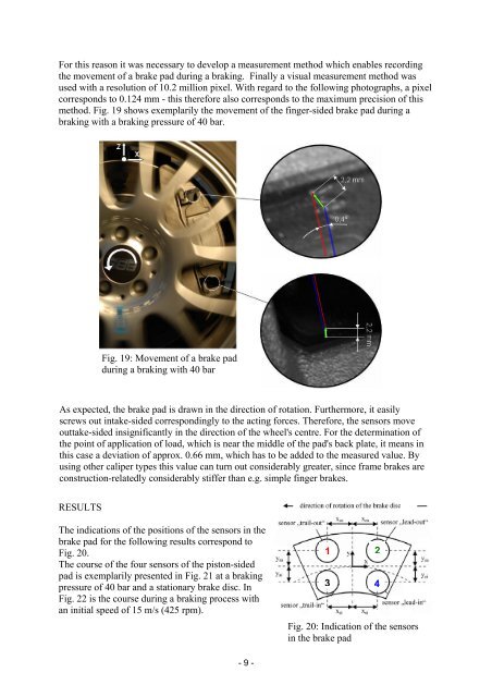
For this reason it was necessary to develop a measurement method which enables recording<br />
the movement of a brake pad during a braking. Finally a visual measurement method was<br />
used with a resolution of 10.2 million pixel. With regard to the following photographs, a pixel<br />
corresponds to 0.124 mm - this therefore also corresponds to the maximum precision of this<br />
method. Fig. 19 shows exemplarily the movement of the finger-sided brake pad during a<br />
braking with a braking pressure of 40 bar.<br />
RESULTS<br />
Fig. 19: Movement of a brake pad<br />
during a braking with 40 bar<br />
As expected, the brake pad is drawn in the direction of rotation. Furthermore, it easily<br />
screws out intake-sided correspondingly to the acting forces. Therefore, the sensors move<br />
outtake-sided insignificantly in the direction of the wheel's centre. For the determination of<br />
the point of application of load, which is near the middle of the pad's back plate, it means in<br />
this case a deviation of approx. 0.66 mm, which has to be added to the measured value. By<br />
using other caliper types this value can turn out considerably greater, since frame brakes are<br />
construction-relatedly considerably stiffer than e.g. simple finger brakes.<br />
The indications of the positions of the sensors in the<br />
brake pad for the following results correspond to<br />
Fig. 20.<br />
The course of the four sensors of the piston-sided<br />
pad is exemplarily presented in Fig. 21 at a braking<br />
pressure of 40 bar and a stationary brake disc. In<br />
Fig. 22 is the course during a braking process with<br />
an initial speed of 15 m/s (425 rpm).<br />
- 9 -<br />
1 2<br />
3 4<br />
Fig. 20: Indication of the sensors<br />
in the brake pad