Design Procedure for Waveguide Filters with Cross-Couplings
Design Procedure for Waveguide Filters with Cross-Couplings
Design Procedure for Waveguide Filters with Cross-Couplings

You also want an ePaper? Increase the reach of your titles
YUMPU automatically turns print PDFs into web optimized ePapers that Google loves.
<strong>Design</strong> <strong>Procedure</strong> <strong>for</strong> <strong>Waveguide</strong> <strong>Filters</strong> <strong>with</strong> <strong>Cross</strong>-<strong>Couplings</strong><br />
Jan Kocbach and Kjetil Folgerø<br />
Nera ASA, Nera Research, N-5020 Bergen, NORWAY. Email: jko@nera.no, kfo@nera.no<br />
Abstract— A new rigorous systematic design procedure<br />
<strong>for</strong> folded waveguide filters <strong>with</strong> cross couplings is presented.<br />
The procedure is a combination of a circuit model analysis<br />
and a full-wave method, and is based on tuning one<br />
dimension at a time <strong>for</strong> simple waveguide structures towards<br />
simple tuning goals. Through examples it is shown how the<br />
procedure can eliminate the need <strong>for</strong> global optimization. As<br />
a consequence of this process, the time needed <strong>for</strong> realization<br />
of filters of this type is greatly reduced. Examples of filters<br />
designed using the described design process are given,<br />
including comparison <strong>with</strong> measurements.<br />
I. INTRODUCTION<br />
The synthesis of the mechanical dimensions of directcoupled<br />
waveguide filters is well described in the literature<br />
(see e.g. [1]-[4]). The corresponding synthesis of multiple<br />
coupled resonator filters, like e.g. folded waveguide filters<br />
<strong>with</strong> cross couplings (see Fig. 1), is more complicated, due<br />
to the much stronger interaction between the couplings <strong>for</strong><br />
these types of filters. This makes it difficult to precisely<br />
determine the physical dimensions of the coupling<br />
structures using the same methods as applied <strong>for</strong> directcoupled<br />
filters.<br />
One often applied method to overcome this difficulty, is<br />
to ignore the interaction between the couplings in the<br />
synthesis of the mechanical dimensions [5], leading to<br />
poor return loss in the synthesized response. To arrive at<br />
the required response, a global full-wave optimization<br />
process is applied subsequently [5]. This global<br />
optimization process is time-consuming. There<strong>for</strong>e, it is<br />
advantageous to use a direct synthesis method <strong>with</strong>out<br />
optimization whenever this is applicable. An example of<br />
such a direct synthesis method has been given in [6] <strong>for</strong><br />
circular dual-mode filters, in which initial values <strong>for</strong> the<br />
mechanical dimensions are first found by considering each<br />
coupling separately, and subsequently these mechanical<br />
dimensions are improved by looking at the interactions<br />
between some of the couplings.<br />
The aim of this paper is to present a new rigorous<br />
systematic design procedure <strong>for</strong> folded waveguide filters<br />
<strong>with</strong> cross couplings, and to show how this procedure may<br />
eliminate the need <strong>for</strong> global optimization in the design of<br />
this type of filters.<br />
b<br />
a<br />
1<br />
2<br />
ai 12<br />
d 14<br />
ai 01<br />
ai 23<br />
bi 23<br />
lr 1<br />
lr 2<br />
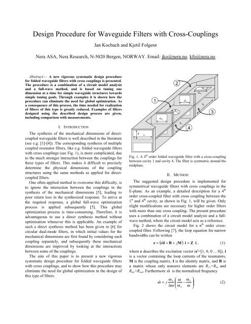
Fig. 1. A 4 th order folded waveguide filter <strong>with</strong> a cross-coupling<br />
between cavity 1 and cavity 4, The filter is symmetric around the<br />
midplane.<br />
II. METHOD<br />
The suggested design procedure is implemented <strong>for</strong><br />
symmetrical waveguide filters <strong>with</strong> cross couplings in the<br />
E-plane. As an example, a detailed description <strong>for</strong> a 4 th<br />
order cross-coupled filter <strong>with</strong> cross coupling between the<br />
1 st and 4 th cavity, as shown in Fig. 1, will be given. Only<br />
slight modifications are necessary <strong>for</strong> higher order filters<br />
<strong>with</strong> more than one cross coupling. The present procedure<br />
uses a combination of a circuit model analysis and a fullwave<br />
method, where the circuit model acts as a reference.<br />
Fig. 2 shows the circuit model <strong>for</strong> a n th order crosscoupled<br />
filter. Following [7], the loop equation <strong>for</strong> narrow<br />
bandwidths can be written<br />
4<br />
( I + R + M) ⋅i<br />
= Z ⋅i<br />
e = ωˆ j , (1)<br />
where e describes the excitation vector (e t =[1, 0, 0 ... 0]), i<br />
is a vector containing the loop currents of the resonators,<br />
M is the coupling matrix, I is the identity matrix, and R is<br />
a matrix whose only nonzero elements are R 11 =R in and<br />
R nn =R out . Furthermore ωˆ is the normalized frequency<br />
ω ⎛ ⎞<br />
0 ω ω<br />
0<br />
ωˆ = j ⎜ ⎟<br />
−<br />
∆ω<br />
(2)<br />
⎝ ω ω<br />
0 ⎠<br />
3
R in M 12 M 23<br />
M 13 M 3,n<br />
Fig. 2. Equivalent circuit of n coupled cavities<br />
Step 1: Step 2: Step 3: Step 4:<br />
IN 1<br />
2<br />
2<br />
a Tune<br />
b<br />
b<br />
ai 01<br />
1<br />
Tune lr 2<br />
a<br />
Calculate lr 1 Tune ai 23<br />
a Tune<br />
3<br />
3<br />
ai<br />
1<br />
12<br />
2<br />
Step 5: Step 6: Step 7: Step 8:<br />
1<br />
1<br />
1<br />
1<br />
b b b<br />
P1<br />
Tune d 14 Tune lr Tune d 14<br />
Tune lr<br />
1<br />
1<br />
R out<br />
P2<br />
Below, the design steps are described in detail <strong>for</strong> the<br />
sample case of a 4 th order cross-coupled filter. The first<br />
four steps are required to realize the folded filter <strong>with</strong>out<br />
cross-couplings. This is straight<strong>for</strong>ward, and is done in a<br />
similar way as presented in [4]. A more comprehensive<br />
procedure is needed to determine the dimensions of the<br />
cross coupling and the length of the cavities adjacent to the<br />
cross coupling. This is explained in step 5 to 8.<br />
1. Calculate the theoretical |S 21 | <strong>for</strong> the input coupling<br />
and the coupling between resonators 1 and 2 as<br />
reference values. Then simulate a waveguide <strong>with</strong> a<br />
single iris in a full-wave simulator (see step 1 in Fig.<br />
3) at ω 0 , and change the dimension of the iris until the<br />
simulated |S 21 | equals the reference value.<br />
2. Calculate the length of the first cavity as<br />
l<br />
r<br />
⎛ 1 ⎞ λ<br />
g 0<br />
= ⎜π<br />
− ( φ + φ )<br />
1 2 ⎟ (5)<br />
⎝ 2 ⎠ 2π<br />
4<br />
4<br />
Fig. 3. Step-by-step illustration of the design procedure <strong>for</strong> the<br />
filter in Fig. 1. P1 and P2 in step 8 refer to port 1 and 2 of the 4-<br />
port, respectively.<br />
where ω is the angular center frequency and ∆ ω is the<br />
0<br />
bandwidth. This leads to the following expressions <strong>for</strong> the<br />
s-parameters<br />
S<br />
4<br />
−1<br />
[ ] , 1<br />
= R R in out<br />
Z (3)<br />
21<br />
2<br />
n<br />
11<br />
1−<br />
2R in<br />
−1<br />
[ ] 1, 1<br />
S = Z<br />
(4)<br />
The realization procedure may be divided into a number<br />
of simple steps (see Fig. 3), leading to a design-process<br />
well suited <strong>for</strong> implementation as an automatic procedure<br />
on a computer. Each step involves the tuning of one<br />
dimension (coupling size or cavity length) in a simple<br />
waveguide structure until the simulated s-parameters fit the<br />
s-parameters of the representative circuit model. The<br />
waveguide structure is kept simple by only including the<br />
couplings and resonators that interact strongly, i.e. either a<br />
single coupling, a single cavity or two coupled cavities.<br />
Simulations are made <strong>for</strong> a single frequency point in the<br />
cases where a coupling is adjusted, and <strong>for</strong> 10-15<br />
frequency points when a cavity length is adjusted.<br />
A fast convergence <strong>for</strong> each step is obtained because (i)<br />
the simulated substructure is very simple, (ii) only one<br />
variable is tuned, (iii) only one or a few frequency points<br />
are considered and (iv) the tuning goals are easy to achieve<br />
<strong>with</strong> few iterations.<br />
b<br />
4<br />
where φ 1 and φ 2 are the phases of S 11 <strong>for</strong> the first and<br />
second coupling, respectively, as found in step 1, and<br />
λ g0 is the guide wavelength at ω 0 . Alternatively, the<br />
cavity length may be tuned in using an analogous<br />
procedure to the one described in step 4 below.<br />
3. Calculate the theoretical |S 21 | <strong>for</strong> the coupling between<br />
resonator 2 and 3 as a reference value. Simulate the<br />
structure shown in step 3 of Fig. 3 at ω 0 , and change<br />
the size of the hole between cavity 2 and 3 until the<br />
simulated |S 21 | equals the reference value.<br />
4. Simulate cavity number 2 as shown in step 4 of Fig. 3.<br />
For |S 21 |, this results in a curve <strong>with</strong> a single peak at<br />
the resonance frequency of the cavity. Adjust the<br />
cavity length until the peak is at ω 0 .<br />
5. Calculate the theoretical |S 21 | <strong>for</strong> the coupling between<br />
resonator 1 and 4 as a reference value. Simulate the<br />
structure shown in step 5 of Fig. 3, in which the<br />
coupling between cavity 1 and 2 of the complete filter<br />
is replaced by a shorted wall, and the input coupling is<br />
removed. Change the size of the hole between cavity 1<br />
and 4 until the simulated |S 21 | equals the reference<br />
value at ω 0 . This gives a first approximation <strong>for</strong> the<br />
physical dimension of the cross-coupling hole.<br />
6. Simulate cavity 1 <strong>with</strong> a coupling hole placed in the<br />
center of the cavity as shown in step 6 of Fig. 3. Find<br />
a new length <strong>for</strong> cavity 1 by adjusting the cavity<br />
length until the peak of |S 21 | is at ω 0 . Note that this<br />
new cavity length is only applied <strong>for</strong> the calculation of<br />
the cross-coupling hole size in step 7.<br />
7. Calculate the theoretical |S 21 | <strong>for</strong> the coupling between<br />
resonator 1 and 4 using equation (3) <strong>with</strong><br />
M 12 =M 23 =M 34 =0. Simulate the structure shown in step
7 of Fig. 3 at ω 0 <strong>with</strong> the cavity length <strong>for</strong> cavity 1<br />
found in step 6, and change the size of the hole<br />
between cavity 1 and 4 until the simulated |S 21 | equals<br />
the reference value at ω 0 . This gives a second<br />
approximation <strong>for</strong> the physical dimension of the<br />
cross-coupling hole. Steps 6 and 7 may be repeated to<br />
get better approximations <strong>for</strong> the cross-coupling hole<br />
size, but this second approximation has been found to<br />
be good enough in the cases considered.<br />
8. Simulate the 4-port in step 8 of Fig. 3. For |S 21 |, this<br />
results in a curve <strong>with</strong> a single peak at the resonance<br />
frequency of the cavity. Adjust the length of cavity 1<br />
(and the length of cavity 4, which is equal to the length<br />
of cavity 1 due to symmetry) until the peak is at ω 0 .<br />
Following steps 1 to 8, the physical dimensions of the<br />
cross-coupled waveguide filter are found.<br />
|S 21<br />
| [dB]<br />
|S 21<br />
| [dB]<br />
-5<br />
-10<br />
-15<br />
-20<br />
Step 1(a)<br />
-25<br />
14 15 16<br />
-30<br />
-40<br />
-50<br />
Step 5<br />
-17.5<br />
-18<br />
-20<br />
-30<br />
-40<br />
Step 1(b)<br />
-20<br />
-25<br />
-30<br />
-35<br />
Step 3<br />
-40<br />
-40<br />
14 15 16 14 15 16 14 15 16<br />
Step 6<br />
-10.5<br />
-11.5<br />
-10<br />
-20<br />
-30<br />
Step 4<br />
-50<br />
-60<br />
-12.5<br />
-25<br />
14 15 16 14 15 16 14 15 16 14 15 16<br />
f [GHz]<br />
f [GHz]<br />
f [GHz]<br />
f [GHz]<br />
-11<br />
-12<br />
Step 7<br />
-10<br />
-15<br />
-20<br />
Step 8<br />
Fig. 4. Simulation results <strong>for</strong> the steps in Fig. 3 <strong>for</strong> the 4 th order<br />
cross-coupled filter. These steps result in the overall filter<br />
response shown in Fig. 5.<br />
III. RESULTS<br />
The method described has been fully automated using<br />
Matlab and the mode-matching/finite element program<br />
Wasp-Net [8]. Using this automated process, a number of<br />
filters at different frequencies (15 GHz - 43 GHz) have<br />
been designed. Results <strong>for</strong> a four cavity and a six cavity<br />
filter are presented below.<br />
A. Four cavity cross-coupled filter<br />
The mechanical dimensions of a four cavity filter <strong>with</strong><br />
center frequency of 15 GHz and bandwidth of 300 MHz<br />
have been synthesized using the described procedure. The<br />
prototype filter has normalized input/output resistances<br />
R R = 1.4886 and coupling matrix<br />
in<br />
= out<br />
⎡ 0 1.10105 0 − 0.18577⎤<br />
M =<br />
⎢ 1.10105 0 0.88528 0 ⎥<br />
⎢ 0 0.88528 0 1.10105 ⎥<br />
⎢⎣<br />
− 0.18577 0 1.10105 0 ⎥⎦<br />
In Fig. 4, simulation results <strong>for</strong> the steps in the<br />
previously described step-by-step procedure are shown.<br />
Five to seven single-frequency calculations at 15 GHz are<br />
used in each of the steps 1, 3, 5 and 7, to tune in the<br />
simulated |S 21 |-values to the theoretical reference values<br />
<strong>for</strong> the structures in Fig. 3. Five to six simulations, each<br />
<strong>with</strong> 15 frequency points, are used in the calculations in<br />
steps 4, 6 and 8, to tune in the cavity lengths so that each<br />
cavity resonates at 15 GHz. The resulting physical<br />
dimensions are given in Fig. 5, along <strong>with</strong> a comparison<br />
between the simulated response of the complete filter and<br />
the ideal circuit response of the prototype filter. All irises<br />
are 1.0 mm thick, and the rectangular coupling hole<br />
between cavity 2 and cavity 3 is placed 2.45 mm from the<br />
end-wall of cavity 2.<br />
The filter has been produced at Nera using machining.<br />
In Fig. 6 measurements are compared to the theoretical<br />
response of the prototype filter. Good agreement is found<br />
between measurements, simulations and prototype filter<br />
response.<br />
To indicate how the present method improves the often<br />
applied design process in which the intercoupling<br />
dependencies are ignored, the filter response after step 5 in<br />
the described design process is shown in Fig. 7. By<br />
comparing Fig. 5 and Fig. 7 it is evident that the present<br />
design procedure gives significantly improved results.<br />
B. Six cavity cross-coupled filter<br />
The mechanical dimensions of a six cavity filter <strong>with</strong> a<br />
cross coupling between the first and last cavity, center<br />
frequency of 18 GHz, and ripple bandwidth of 500 MHz,<br />
has been synthesized using the described procedure <strong>with</strong> a<br />
slight modification. The prototype filter has normalized<br />
input/output resistances R in<br />
= R out<br />
= 1. 1930 and coupling<br />
matrix<br />
⎡ 0 0.9498 0 0 0<br />
⎢ 0.9498 0 0.6661 0 0<br />
⎢<br />
M =<br />
0 0.6661 0 0.6434 0<br />
⎢ 0 0 0.6434 0 0.6661<br />
⎢ 0 0 0 0.6661 0<br />
⎢<br />
⎣−<br />
0.0240 0 0 0 0.9498<br />
− 0.0240⎤<br />
0 ⎥<br />
0 ⎥<br />
0 ⎥<br />
0.9498 ⎥<br />
0 ⎥<br />
⎦<br />
In Fig. 8 the simulated response of the designed filter is<br />
compared to the ideal circuit response of the prototype<br />
filter. From the figure it may be seen that there is good<br />
correspondence between the two cases. However, if the<br />
position of the two transmission zeros is critical, some<br />
fine-optimization is necessary.
0<br />
-10<br />
Theory<br />
Simulation<br />
0<br />
-10<br />
Theory<br />
Simulation<br />
|S 21<br />
|, |S 11<br />
| [dB]<br />
-20<br />
-30<br />
-40<br />
|S 21<br />
|, |S 11<br />
| [dB]<br />
-20<br />
-30<br />
-40<br />
-50<br />
-50<br />
-60<br />
14 14.5 15 15.5 16<br />
Frequency [GHz]<br />
Fig. 5. Comparison between prototype filter response and<br />
simulated response of the four cavity cross-coupled filter. Filter<br />
dimensions are a=15.799 mm, b=7.899 mm, lr 1 =11.174 mm,<br />
lr 2 =12.329 mm, ai 01 =7.071 mm, ai 12 =4.192 mm, ai 23 =6.781 mm,<br />
bi 23 =3.0 mm and d 14 =4.192 mm.<br />
-60<br />
14 14.5 15 15.5 16<br />
Frequency [GHz]<br />
Fig. 7. The simulated response after step 5 in the described<br />
design process compared to the prototype filter response. In this<br />
case d 14 =4.293 mm, lr 1 =11.063 mm, and the other dimensions<br />
are as given in Fig. 5.<br />
0<br />
-10<br />
Theory<br />
Measurement<br />
0<br />
-10<br />
Theory<br />
Simulation<br />
|S 21<br />
|, |S 11<br />
| [dB]<br />
-20<br />
-30<br />
-40<br />
|S 21<br />
|, |S 11<br />
| [dB]<br />
-20<br />
-30<br />
-40<br />
-50<br />
-50<br />
-60<br />
-60<br />
14 14.5 15 15.5 16<br />
Frequency [GHz]<br />
Fig. 6. Comparison between prototype filter response and<br />
measured response of the four cavity cross-coupled filter.<br />
-70<br />
17 17.5 18 18.5 19<br />
Frequency [GHz]<br />
Fig. 8. Comparison between prototype filter response and<br />
simulated response of the six cavity cross-coupled filter.<br />
IV. CONCLUSION<br />
A general design procedure <strong>for</strong> folded waveguide filters<br />
<strong>with</strong> cross couplings has been presented. The usefulness of<br />
the method has been verified through simulations and<br />
measurements. The procedure has currently been applied<br />
to symmetric cross-coupled waveguide filters <strong>with</strong> one<br />
cross coupling, but can also be extended to filters <strong>with</strong><br />
several cross couplings.<br />
REFERENCES<br />
[1] G. L. Matthaei, L. Young, and E. M. T. Jones, "Microwave<br />
filters, impedance-matching networks, and coupling<br />
structures," New York: McGraw-Hill, 1964 (Reprint<br />
Norwood: Artech House, 1980)<br />
[2] M. Guglielmi, "Simple CAD procedure <strong>for</strong> microwave<br />
filters and multiplexers ," IEEE Trans. Microwave Theory<br />
Tech., vol. 42, pp. 1347-1352, July 1994<br />
[3] S. Yin, T. Vasilyeva, and P. Pramanick, "Use of threedimensional<br />
field simulators in the synthesis of waveguide<br />
round rod bandpass filters," Int. J. RF and Microwave<br />
Computer-Aided Engineering vol. 8, no. 6, pp 484-497,<br />
Nov 1998<br />
[4] K. Folgerø, "Step-by-step procedure <strong>for</strong> design of<br />
waveguide filters <strong>with</strong> HFSS," Ansoft HFSS User<br />
Workshop, Los Angeles, January 2001<br />
[5] T. Shen, K. A. Zaki, and A. E. Atia, "Full-wave design of<br />
canonical waveguide filters by optimization," 2001 IEEE<br />
MTT-S Int. Microwave Symp. Digest, vol. 3 pp. 1487-<br />
1490, June 2001<br />
[6] J. R. Montejo-Garai, and J. Zapata, "Full-wave design and<br />
realization of multicoupled dual-mode circular waveguide<br />
filters," IEEE Trans Microwave Theory Tech vol. 43, no. 6,<br />
pp. 1290-1297, 1995<br />
[7] A. E. Atia, and A. E. Williams, "A solution <strong>for</strong> narrow-band<br />
coupled cavities," COMSAT Technical Memorandum CL-<br />
39-70, 1970<br />
[8] “Wasp-Net: Manual and design examples", Microwave<br />
Innovation group, Bremen, Germany, 2001