product information - Gfo Europe S.p.A.
product information - Gfo Europe S.p.A.
product information - Gfo Europe S.p.A.

Create successful ePaper yourself
Turn your PDF publications into a flip-book with our unique Google optimized e-Paper software.
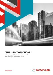
ICT Networks<br />
Scalable solutions for high performance<br />
network infrastructures<br />
Cabling Solutions
Contents<br />
page<br />
About us 2<br />
ICT Networks 7<br />
ICT Product Overview 10<br />
page<br />
Product features: Legend of pictographs 14<br />
The most important test procedures and their functions 16<br />
ROHS – WEEE – REACH 20<br />
Copper Technology<br />
Product overview and selection guide for copper data cables 21<br />
At a glance guide: Copper data cables, by Category 22<br />
At a glance guide: Copper connecting hardware, by Category 24<br />
Data cables, shielded 26<br />
Data cables, unshielded 56<br />
Telephone cables 62<br />
Trunks 68<br />
Patch cords 73<br />
Connecting technology Cat.7 A<br />
, shielded 100<br />
Connecting technology Cat.6 A<br />
, shielded 102<br />
Fibre Optic Technology<br />
Product overview and selection guide for optical fibres 176<br />
Checklist: Fibre types, applications and maximum link lengths 177<br />
Singlemode fibres 178<br />
Multimode fibres 184<br />
Fibre optic cables - <strong>product</strong> overview 188<br />
Product overview and selection guide<br />
for indoor and universal cables 190<br />
Indoor cables 191<br />
Universal cables 200<br />
Data Cabinets & Racks<br />
Data cabinets & racks 266<br />
Cold aisle containment 272<br />
Data cabinet & rack accessories 275<br />
Data centRe<br />
Datwyler Data Centre Solution 280<br />
MHD – Modular High Density distribution system 298<br />
Wireless<br />
Wireless solutions 309<br />
Multimedia<br />
Multimedia solution 317<br />
General Information<br />
Copper technology 320<br />
Fibre optic technology 331<br />
Technical terms used in data cable technology 337<br />
Panorama – Management Software Solution 343<br />
Connecting technology Cat.6/E A<br />
, shielded 108<br />
Connecting technology Cat.6, shielded 111<br />
Connecting technologyCat.5e, shielded 114<br />
Connecting technology Cat.6, unshielded 115<br />
Connecting technology Cat.3, unshielded 119<br />
Faceplates 120<br />
Patch panels 138<br />
Industrial 150<br />
Accessories 162<br />
Subfloor systems 170<br />
Product overview and selection guide for outdoor cables 213<br />
Outdoor cables 214<br />
Trunks 236<br />
Pigtails 238<br />
Patch cords 239<br />
Connectors 248<br />
Faceplates 251<br />
Panels & enclosures 252<br />
Accessories 263<br />
Fibre to the Home (FTTH) 346<br />
Safety cable systems 352<br />
Building automation 358<br />
Elevator cable systems 366<br />
Index of article numbers 370<br />
General Information Multimedia Wireless Data Centre Cabinets & Racks Fibre Optics Copper
Datwyler<br />
A reliable partner at your side<br />
Delivering excellence – every time, everywhere<br />
The “lifeblood“ of a modern public or commercial building is the<br />
functionality and reliability of the system solutions for communications,<br />
building automation, power supply, safety and lifts. This is true of any<br />
such construction, irrespective of whether it is an office block, hotel,<br />
sports stadium, television studio or a tunnel.<br />
Choose a reliable system partner right from the start: choose Datwyler!<br />
Hotels, hospitals<br />
Office blocks<br />
Government buildings, universities<br />
Shopping centres<br />
Data centres<br />
Tunnels<br />
2 Datwyler
Datwyler is a leading provider of total solutions for the electrical and communications<br />
infrastructure of public and commercial buildings and of data<br />
centres as well as for Fibre to the home (FTTH) networks.<br />
Being a solid, reliable company about to celebrate its 100th year of operation,<br />
Datwyler leads the way in innovations for applications such as ICT networks,<br />
power supply, fire safety, building automation and lifts.<br />
Datwyler is a one-stop source of customised solutions for all your specific applications<br />
– with all the necessary test certificates, authorisations and approvals<br />
and with long-term warranties.<br />
Event arenas<br />
Datwyler has successfully acted not only as a supplier of innovative <strong>product</strong>s<br />
and system solutions but also as the lead or main contractor who, working in<br />
close cooperation with local partners, covers the whole value chain: from site<br />
surveys, conception and system engineering through installation, logistics<br />
and turnkey supply to documentation and system maintenance.<br />
The Datwyler Cabling Solutions division is part of Datwyler Group, an international<br />
multi-niche player with some 5000 employees which generates approximately<br />
1000 million Euro in sales revenue.<br />
FTTx projects<br />
Datwyler<br />
3
Datwyler<br />
Worldwide expertise in turnkey creation, multi-site projects and services<br />
Turnkey installations<br />
Maintenance<br />
Communication<br />
Energy<br />
Datwyler does not only supply integrated system solutions, but<br />
has positioned itself successfully as a turnkey partner: for all<br />
manner of purpose-built constructions including multi-site<br />
projects, for data cenres and for FTTx projects. Our successful<br />
processing of turnkey projects derives from our high-level<br />
skills in developing and manufacturing the required<br />
<strong>product</strong>s and solutions, our comprehensive<br />
applications expertise, our international<br />
presence and our globally<br />
established partner network.<br />
Advice<br />
Electrical and<br />
communications<br />
infrastructure<br />
Safety<br />
Building automation<br />
Planning<br />
Of course, all our processes are ISO 9001:2008 / ISO<br />
14001:2004 certified.<br />
Implementation<br />
Our international presence and our worldwide, actively<br />
managed and certificated partner network have also<br />
proved invaluable in the multi-site projects of major<br />
clients. National and international companies rely on<br />
Datwyler on-the-spot site audits. Using the site surveys<br />
as a base, our engineering experts work out customised<br />
solutions with uniform standards for all the sites<br />
concerned. Our total solutions package is rounded<br />
off by the implementation and assurance of regular<br />
operations. While operations are running, we provide<br />
servicing and maintenance work to optimise your infrastructure<br />
solution. These MAC (move, add, change)<br />
services increase the performance and working life of<br />
your equipment.<br />
High-quality solutions for all your applications<br />
Year on year, Datwyler invests in even better materials<br />
and process technologies, <strong>product</strong>ion resources<br />
and test methods. This is why our system solutions<br />
always keep ahead of the current norms and repeatedly<br />
set new standards. The important functions<br />
which our solutions must deliver in practice demand<br />
the highest possible level of safety and reliability.<br />
This is why we measure each <strong>product</strong> against stringent<br />
quality standards before it leaves the company.<br />
Our sustainable solutions provide you with highlevel<br />
operational reliability coupled with low operating<br />
costs. The proof that Datwyler systems can deliver<br />
these benefits has been evident for many years<br />
in thousands of installations around the world. In addition,<br />
we have a particularly keen eye for consistent,<br />
intelligent solutions that simplify planning, sourcing<br />
and installation and shorten your construction times.<br />
We have the solutions for all your applications,<br />
whatever they are – high-speed communications<br />
networks, modern energy distribution, monitoring<br />
and control services, fire alarm systems or lift cabling.<br />
Or you may want to integrate new systems, interconnect<br />
and automate existing systems or simply ensure<br />
a reliable power supply. All this is possible with our<br />
carefully thought out, pre-assembled and prefabricated<br />
subsystems.<br />
Just tell us how, when and where<br />
Besides quality and <strong>product</strong> price, the logistics performance<br />
capability of suppliers is a decisive factor in<br />
the successful handling of construction projects. This<br />
is particularly true of major projects. With its years of<br />
experience and high logistics competences, Datwyler<br />
can handle even time-critical major projects<br />
smoothly and to the complete satisfaction of customers.<br />
Just-in-time deliveries at the right place are all<br />
in a day’s work for us and our partners.<br />
4 Datwyler
Besides delivering straight to the construction site, we<br />
also offer additional logistics services (time slots, prefitted<br />
and pre-assembled <strong>product</strong>s etc.). Many customers<br />
and suppliers have a direct link to our IT system<br />
for rapid and flexible order processing. As regards<br />
cable pre-assembly, Datwyler also has wide-ranging<br />
expertise, the <strong>product</strong> of decades of experience. In our<br />
modern cable cutting centre, the engineering department<br />
passes the cutting orders electronically without<br />
any media discontinuity straight to the <strong>product</strong>ion<br />
area. Our efficient order communication system with<br />
all our customers is due to years of experience with<br />
B2B interfaces.<br />
In many countries Datwyler works in close co-operation<br />
with independent distribution partners. Thus, our<br />
customers can rely on the consistently high quality<br />
standard of all Datwyler <strong>product</strong>s and solutions whilst<br />
benefiting from local contacts and logistics services.<br />
We support you in realising your infrastructure<br />
project – reliably, capably, complete and with the<br />
highest quality!<br />
Datwyler<br />
5
High-speed<br />
communication<br />
ICT Networks<br />
6<br />
Datwyler
From analogue telephony up to 10/40/100G; from Local Area Network and<br />
high-speed data centre cabling to entire carrier and Fibre to the home networks<br />
– Datwyler is your preferred partner for top-quality, reliable and future-proof<br />
ICT networks in copper and fibre optics. With outstanding <strong>product</strong>s and<br />
system solutions, Datwyler set standards for quality, performance and<br />
investment protection.<br />
Media convergence in communication is an irreversible trend,<br />
and the demand for ever increasing bandwidth continues to<br />
boom. IP technology is merging telephone, television and Internet.<br />
Multimedia – a magic word just a few years ago – is<br />
already reality.<br />
Future-proof thanks to high-quality solutions<br />
With the technical possibilities to constantly increase transfer<br />
rates, requirements for cable systems are becoming more demanding.<br />
The high-quality solutions of Datwyler exploit the<br />
full potential of networks and offer high investment security<br />
for the future. The comprehensive <strong>product</strong> range extends<br />
from single cables and components to complete end-to-end<br />
systems.<br />
Modular solutions for every application<br />
Datwyler modular solutions are suitable for all sizes and<br />
types of networks – from residential cabling to cabling systems<br />
for offices or industrial buildings to campus, access, or carrier<br />
networks for thousands of users. Telecom providers rely on<br />
our experience and know-how, as do banks, insurance companies,<br />
universities, hospitals, airports, car manufacturers and<br />
industrial companies.<br />
Datwyler<br />
7
System solutions<br />
from a single source<br />
ICT Networks<br />
Leading know-how<br />
As a provider of total solutions for <strong>information</strong> and telecommunication networks,<br />
Datwyler possesses extensive know-how accumulated over decades:<br />
- Almost 100 years of experience in cable <strong>product</strong>ion.<br />
- Leading material, <strong>product</strong>ion and process know-how in the fabrication of copper<br />
and fibre-optic cables and components.<br />
- Solid electro-technical competency.<br />
- Close collaboration with renowned technical universities, international standards<br />
committees, and independent testing institutes.<br />
- Broad systems competence.<br />
Diverse applications<br />
In the field of ICT networks Datwyler concentrates on communication infrastructures<br />
for public and commercial buildings and for FTTx networks.<br />
Some examples are:<br />
- Office, industrial and exhibition buildings<br />
- Data centres<br />
- Hotels and hospitals<br />
- Stadiums, theatres, concert halls<br />
- Airports and train stations<br />
- FTTx projects of public utility companies and energy supply companies<br />
In these market segments we can also flexibly meet individual customer requirements<br />
– up to and including turnkey and multi-site projects – with our cost-effective, modular<br />
system solutions and compehensive services.<br />
8 Datwyler
Complete system solutions<br />
- Screened and unscreened copper system solutions (categories<br />
3 to 7 A<br />
) for the transmission of voice, data, video, CATV,<br />
control signals and remote power (power over Ethernet,<br />
PoE+).<br />
- Innovative fibre-optic system solutions with singlemode and<br />
multimode optical fibres for indoor and outdoor applications,<br />
from LAN backbones to FTTH in-house cabling.<br />
- Software solution for building, technology and network<br />
management.<br />
- Extensive services ranging from consulting and planning via<br />
pre-fabrication, logistics and installation to system maintenance.<br />
- Established worldwide, actively managed and certificated<br />
partner network.<br />
- Rigorous training and certification programme to guarantee<br />
optimal installation quality of our systems and solutions.<br />
- Long-term warranty covering the entire system.<br />
Yangshan Deepwater Port administration centre, Shanghai<br />
Selected reference projects<br />
Airrail Center Frankfurt a.M. Rathbones London<br />
Party school campus Hangzhou Dubai Motor City Dubai<br />
Kunming Airport Kunming Swisscom IT Services Zollikofen<br />
UBI Banca (1964 branch offices) Bergamo UBS central administration, Flurhof Zurich<br />
Swiss parliament building Berne Allianz Arena Munich<br />
Dexia BIL Luxembourg KPMG German headquarters Berlin<br />
Focus on customer value<br />
Datwyler stands for more than just the fabrication and distribution<br />
of <strong>product</strong>s. For your ICT networks we offer future-proof,<br />
modular, customised one-source solutions for all your specific<br />
applications – as a uniquely attractive overall package, with all<br />
the necessary test certificates, authorizations and certificates<br />
and with long-term warranties.<br />
The interaction of these elements creates added value. As a<br />
customer you benefit from maximum network availability and<br />
high investment protection, even with regard to future applications,<br />
expansions and changes.<br />
Allianz Arena, Munich<br />
Datwyler<br />
9
Product Overview<br />
Integrated, future-proof cabling solutions for ultimate<br />
reliability in voice, data, video and CATV applications<br />
More than just <strong>product</strong>s<br />
With the complete packages offered by Datwyler you are<br />
opting for comprehensive application-neutral and providerindependent<br />
system solutions encompassing the communication<br />
infrastructure for office and industry environments and for<br />
FTTx.<br />
For Datwyler, quality testing and quality management begin<br />
during the cable <strong>product</strong>ion process. Here relevant electrical<br />
and mechanical data are recorded online and automatically<br />
compared with the predefined specifications. The performance<br />
values of our cables generally exceed current standards and<br />
drafts by considerable margin.<br />
Faceplate<br />
for PS-TERA TM module<br />
Copper patch cords<br />
PS-TERA TM /RJ45<br />
Module PS-TERA TM<br />
1/8 Cat.7 A<br />
Copper patch panels<br />
MPS 12x, 16x, 24x, 32x<br />
for MS 1/8 or PS-TERA TM<br />
modules<br />
Datwyler follows the same procedure for the <strong>product</strong>ion of connection<br />
components, e.g. data outlets, patch panels and patch<br />
cables for copper and fibre optic systems.<br />
Marking of individual components ensures that data measured<br />
up to the time of <strong>product</strong>ion can be called up at any point in the<br />
future. This gives users or investors a high degree of certainty<br />
that the <strong>product</strong>s used and manufactured provide the durability<br />
demanded by them.<br />
Faceplate<br />
for MS-K Plus 1/8<br />
modules<br />
RJ45 module<br />
MS-K Plus 1/8 Cat.6 A<br />
Industrial<br />
data outlet IP67<br />
for MS 1/8 module<br />
Industrial<br />
REG adapter MS IP20<br />
for MS 1/8 module<br />
Industrial<br />
patch cord PUR<br />
Copper patch<br />
cords<br />
Data outlet<br />
CSA Plus 2/8<br />
Cat.6 A<br />
(IEC)<br />
Copper patch panel<br />
CSA 24/8 Plus Cat. 6 A<br />
10 Datwyler
FO patch panel<br />
OV-A<br />
FO data outlets<br />
FO patch cords<br />
FO wall-mounted<br />
distribution box<br />
OV-W<br />
FO Indoor cables<br />
Copper data cables (solid) /<br />
copper flexible cables<br />
FO Universal cables<br />
FO Safety cables<br />
e.g.:<br />
Cat.6 A<br />
: 7060 4P<br />
Cat.7: 7080 4P<br />
better than Cat.7 A<br />
:<br />
7150 4P<br />
Multimedia CAT TV Balun,<br />
active balun up to 862 MHz<br />
for the distribution of CATV signals<br />
Multimedia CAT TV Panel,<br />
active distribution panel up to 862 MHz<br />
for the distribution of CATV signals in LANs<br />
Datwyler<br />
11
Product Overview<br />
Copper<br />
Fibre opticS<br />
Cables<br />
shielded / unshielded<br />
Connection<br />
shielded / unshielded<br />
Cables<br />
Connection<br />
Copper installation /<br />
flexible cable<br />
Copper modules<br />
Fibre optic indoor cable<br />
Fibre optic adapters and couplers<br />
Copper patch cords<br />
Copper patch panels<br />
Fibre optic universal<br />
and safety cable<br />
Fibre optic patch panels<br />
Copper multiple cables (trunks),<br />
highly flexible, pre-assembled<br />
Copper faceplates<br />
Fibre optic patch<br />
and adapter cable<br />
Fibre optic faceplates<br />
Copper multiple cable (trunk),<br />
highly flexible, pre-assembled<br />
Floor-box solutions<br />
Fibre optic multiple cable (trunk)<br />
Fibre optic wall mounted<br />
distribution boxes<br />
Measurement cables<br />
Accessories<br />
Fibre optic multiple<br />
cable (trunk)<br />
BreakOut<br />
Fibre optic accessories<br />
Are you looking for a building, technology and network management software which enables effective planning, management, documentation<br />
and control of all objects and processes around your infrastructure? Feel free to ask for details about “Panorama”!<br />
12 Datwyler
Rack Systems<br />
Data centre<br />
solutionS<br />
Wireless Solutions<br />
multimediA<br />
Network-/Server racks<br />
FO-DCS and MHD<br />
Modular High-Speed and<br />
High Density cabling systems<br />
WiFi<br />
Powerful Wireless Fidelity<br />
Multimedia and<br />
switching<br />
Network rack<br />
FO-DCS modular subrack<br />
WiFi Arrays<br />
CAT TV Panel<br />
active distribution panel up to 862 MHz<br />
for the distribution of CATV signals<br />
Server rack<br />
FO-DCS MTP-LCD plug-in modules<br />
Transformers<br />
CAT TV Balun<br />
active balun up to 862 MHz<br />
for the distribution of CATV signals<br />
Wall mounted box<br />
MHD multiple cables (trunks)<br />
pre-assembled copper data cables<br />
Access points<br />
Network camera<br />
Minirack<br />
MHD FO distribution cartridges<br />
Management system<br />
Video monitoring system<br />
IT rack accessories<br />
MHD multiple cables<br />
pre-assembled FO data cables<br />
WiFi accessories<br />
Switches<br />
Datwyler<br />
13
Product features<br />
The following pictograms show the essential features of<br />
our <strong>product</strong>s and give an easy reference.<br />
They are allocated to the articles on the data sheets<br />
and provide you with a quick overview<br />
Zero halogen,<br />
non corrosive gases<br />
Cables are halogen-free<br />
and reduce possible damage to<br />
health or material to a minimum.<br />
IEC 60754-1 and IEC 60754-2,<br />
EN 50267-2-1, EN 50267-2-2, EN 50267-2-3<br />
VDE 0482-267 part 2-1, 2-2 and 2-3<br />
Flame propagation<br />
Cables use a high performance,<br />
flame retardant material<br />
that is self extinguishing.<br />
IEC 60332-1-2,<br />
EN 60332-1-2,<br />
VDE 0482-332-1-2<br />
Flame spread<br />
Cables are flame resistant<br />
and prevent the propagation of a<br />
fire from one location to another<br />
IEC 60332-3-22 to 25 cat. A-D,<br />
EN 60332-3-22 bis 25 cat. A-D,<br />
VDE 0482-332-3-22 to 25 cat. A-D<br />
Smoke density<br />
Cables emit minimum smoke<br />
in the event of fire.<br />
Exit routes and fire brigade access<br />
are not restricted.<br />
IEC 61034-1 and IEC 61034-2,<br />
EN 61034-1 and EN 61034-2,<br />
VDE 0482-1034 part 1 and 2<br />
Circuit integrity<br />
[FE/PH]<br />
Cables with circuit integrity<br />
guarantee the function of a single<br />
cable for a defined duration. (FE is<br />
for flame time and influence time)<br />
IEC 60331-1, IEC 60331-2 and part 21,23, 25,<br />
EN 50200 with Annex E, EN 50362,<br />
VDE 0472 part 814, VDE 0482-200,<br />
VDE 0482-362,<br />
BS 8434-2, BS 6387 (cat. C/W/Z)<br />
System Circuit<br />
integrity<br />
[E30-E90]<br />
Cables (together with certified fixing<br />
systems) guarantee enhanced circuit<br />
integrity of the complete electrical cable<br />
installation for a defined time.<br />
(E30=30 minutes, E60=60 minutes,<br />
E90=90 minutes)<br />
DIN 4102 part 12 [E30-E90]<br />
NBN 713.020 (Rf1, Rf1½)<br />
14 Datwyler
M<br />
modular<br />
Modular design of the connection technique with<br />
changeable modules. Providing the possibility of faster<br />
maintenance and hassle-free alterations in the event of<br />
increased user demand.<br />
EMV<br />
Power over Ethernet<br />
PoE+ (IEEE 802.3at)<br />
shielded<br />
30 W<br />
Fully shielded faceplates/outlets, patch panels and<br />
data cables, ensuring the compliance with the EMC<br />
guidelines according to EN55022 and indisrupted operation.<br />
The compatibility with other systems in the environment<br />
is guaranteed due to the excellent shielding<br />
of all cables and components.<br />
for copper data cables with AWG 22<br />
Power over Ethernet<br />
PoE+ (IEEE 802.3at)<br />
30 W<br />
for copper data cables < AWG 22<br />
Power over Ethernet<br />
PoE (IEEE 802.3af)<br />
15 W<br />
for copper data cables<br />
ROHS<br />
Directive<br />
2011/65/EU<br />
of the <strong>Europe</strong>an Parliament and of the Council<br />
of 08. June 2011 on the restriction of the use<br />
of certain hazardous substances in electrical<br />
and electronic equipment. (revised form)<br />
Datwyler<br />
15
The most important test<br />
procedures and their functions<br />
Test on gases evolved during combustion<br />
This test procedure provides <strong>information</strong> if the insulation material of the cable sheath<br />
creates corrosive gases in the event of fire.<br />
Halogen parts or other material in small quantities<br />
can be easily identified with this test due to the strong<br />
change of pH and conductivity.<br />
The conductivity is < 10mS/mm<br />
Standards<br />
- IEC 60754-1 and IEC 60754-2<br />
- EN 50267-2-1, EN 50267-2-2<br />
- EN 50267-2-3<br />
- VDE 0482-267 part 2-1, 2-2 and 2-3<br />
Test for vertical flame propagation<br />
(single insulated wire or cable)<br />
This test method tests a cable sample (length: 60 cm)<br />
for burning behaviour.<br />
The flame must extinguish itself, and the burn damage<br />
must not reach the upper end of the cable sample.<br />
Standards<br />
- IEC 60332-1-2<br />
- EN 60332-1-2<br />
- VDE 0482-332-1-2<br />
Test for vertical flame spread<br />
(bunched wires or cables)<br />
This test method tests a cable bundle<br />
(length: 360 cm) with regard to fire propagation.<br />
The flames must extinguish themselves,<br />
and burn damage must not exceed a defined<br />
height.<br />
Standards<br />
- IEC 60332-3-22 up to 25 Cat A-D<br />
- EN 60332-3-22 up to 25 Cat. A-D<br />
- VDE 0482-332-3-22 up to 25 Cat. A-D<br />
Measurement of smoke density<br />
This test checks smoke development when burning<br />
the cable or the impairment of the visibility by burning<br />
cables.<br />
The reduction in light transparency is measured in a<br />
standard chamber.<br />
Standards<br />
- IEC 61034-1 and IEC 61034-2<br />
- EN 61034-1 and EN 61034-2<br />
- VDE 0482-1034 part 1 and 2<br />
16 Datwyler
The most important test<br />
procedures and their functions<br />
Test of circuit integrity (FE/PH)<br />
This test establishes whether a single cable can maintain circuit<br />
integrity during and after exposure to a fire for a time period of<br />
at least 180 minutes. Cables which fulfil the requirements of this<br />
test are marked with ”FE180“ after their type designation.<br />
There is no obligation to test the cable for functional integrity<br />
beyond the designated period.<br />
Remark:<br />
This test is not equivalent to<br />
the test for functional integrity<br />
in accordance with DIN 4102-12<br />
Test of<br />
circuit integrity<br />
(fire and water)<br />
- BS 6387 (cat.W) [650°C, 3A]<br />
- VdS 3423 [>830°C, 3A]<br />
- EN 50200 Annex E [>830°C, 2A]<br />
Test of circuit integrity<br />
(fire and mechanical shock)<br />
- IEC 60331-1/-2 [>830°C, 2A]<br />
- EN 50200 (PH) [>830°C, 2A]<br />
- EN 50362 [> 830°C, 2A]<br />
- BS 6387 (cat.Z) [950°C, 3A]<br />
Test of circuit integrity<br />
(fire alone)<br />
- IEC 60331-11/-21/-23/-25 [>750°C]<br />
- BS 6387 (cat. C) [950°C]<br />
- VDE 0472-814 [>750°C]<br />
Test of system circuit integrity<br />
of electrical cable installations<br />
This standard describes the requirements and the<br />
actions to achieve the enhanced functional integrity<br />
of complete electrical cable installations in the event<br />
of fire.<br />
While the circuit integrity (FE/PH) provides only for the<br />
test of single cables, the cables here are tested in connection<br />
with practical support and fixing systems.<br />
It is important to appreciate that there is no connection<br />
between the two standards - circuit integrity (FE/<br />
PH) and system circuit integrity (E).<br />
The test is carried out and certified from state recognised<br />
institutes.<br />
Standards<br />
- DIN 4102 part 12 (E30-E90)<br />
- NBN 713-020 (Rf1, Rf1 1 / 2<br />
)<br />
Better than the standard!<br />
This test (E30-E90) is the only worldwide standard for guaranteeing functional integrity of the<br />
complete electrical cable installation, including the support and fixing components, under normal<br />
operating conditions.<br />
Datwyler<br />
17
The most important test<br />
procedures and their functions<br />
Temperature change and humidity<br />
This test procedure checks the electrical parameters (LF and HF) of<br />
a data cable following temperature or humidity changes. Test conditions<br />
for the temperature and humidity dependent measurements<br />
must simulate the worst conditions.<br />
Standard<br />
- IEC 60794-1-2F1<br />
Tensile performance<br />
This test checks the behaviour of the electrical LF and HF<br />
parameters as a function of the pulling force of the data<br />
cable, such as that occurring during draw-in. This is not a<br />
destructive test.<br />
This means that the cable is loaded with the maximum<br />
allowable pulling force.<br />
Standard<br />
- IEC 60794-1-2-E1B<br />
Repeated bending<br />
The behaviour of a data cable is determined by bending a cable sample forwards and<br />
backwards 180 degrees several times. Afterwards, the cable must still fulfil the electrical<br />
LF and HF parameters according to the EN 50173 standard.<br />
Standard<br />
- IEC 60794-1-2-E6<br />
Hammer blow<br />
In order to determine the resistance of a data cable against impacts,<br />
a wedge is allowed to fall vertically onto the cable. Afterwards, the<br />
cable must still fulfil the electrical LF and HF parameters according to<br />
the EN 50173 standard.<br />
18 Datwyler
The most important test<br />
procedures and their functions<br />
Impact<br />
The fall of a heavy tool, device, stone, etc. onto the cable is simulated here.<br />
The weight is allowed to fall vertically onto an intermediate steel piece that<br />
transmits the force to the cable sample. No damage to the cable sheath<br />
may occur.<br />
Standard<br />
- IEC 60794-1-2-E4<br />
Crush resistance<br />
The purpose of this test is to determine the ability of a data cable<br />
to withstand transverse pressure. After that, the electrical LF and<br />
HF parameters must still correspond to the EN 50173 standard.<br />
Standard<br />
- IEC 60794-1-2-E3<br />
Torsion<br />
During installation, a fibre optic cable must withstand torsion<br />
forces in addition to tension, transverse pressure and bending<br />
loads. Thus, a cable sample is turned about its own axis. Attenuation<br />
deviations are documented during the test. Neither<br />
fibre nor sheath materials may be damaged during the test.<br />
Standard<br />
- IEC 60794-1-2-E7<br />
Water penetration<br />
method A<br />
method B<br />
This method checks whether all interstices of a fibre optic<br />
outdoor cable are continuously filled with a compound that<br />
prevents water from entering the cable. Determining test<br />
criteria are the time and the maximum dispersal of the water<br />
within the sample. Datwyler uses the more difficult test<br />
method B exclusively.<br />
Standard<br />
- IEC 60794-1-2-F5-A/B<br />
Datwyler<br />
19
ROHS – WEEE – REACH<br />
Statement from Datwyler:<br />
As an environmentally conscious manufacturer<br />
and supplier of cabling solutions it is<br />
our concern not to use any environmentally<br />
harmful substances in our <strong>product</strong>s.<br />
Based on current <strong>information</strong>, the hereinmentioned<br />
guidelines / regulations for<br />
banned substances are fully complied with.<br />
Exceptions are noted as such on the relevant<br />
data sheet.<br />
ROHS<br />
DIRECTIVE 2002/95/EC<br />
OF THE EUROPEAN PARLIAMENT<br />
AND OF THE COUNCIL<br />
of 08. June 2011 on the restriction of the use of certain<br />
hazardous substances in electrical and electronic<br />
equipment<br />
WEEE<br />
DIRECTIVE 2002/96/EC<br />
OF THE EUROPEAN PARLIAMENT AND OF THE COUNCIL<br />
of 4 July 2012 on waste electrical and electronic<br />
equipment (revised form)<br />
REACH<br />
REGULATION (EC) No 1907/2006<br />
OF THE EUROPEAN PARLIAMENT AND OF THE COUNCIL<br />
of 18 December 2006 concerning the Registration,<br />
Evaluation, Authorisation and Restriction of Chemicals<br />
(REACH), establishing a <strong>Europe</strong>an Chemicals Agency,<br />
amending Directive 1999/45/EC and repealing<br />
Council Regulation (EEC) No 793/93 and Commission<br />
Regulation (EC) No 1488/94 as well as Council Directive<br />
76/769/EEC Commission Directives 91/155/EEC,<br />
93/67/EEC, 93/105/EC and 200/21/EC<br />
and<br />
COMMISSION REGULATION (EU) No 143/2011<br />
of 17 February 2011 amending Annex XIV to Regulation<br />
(EC) No 1907/2006 of the <strong>Europe</strong>an Parliament and<br />
of the Council on the Registration, Evaluation, Authorisation<br />
and Restriction of Chemicals<br />
20 Datwyler
Copper<br />
Product overview and selection guide<br />
for copper data cables<br />
Selection criteria<br />
The Datwyler <strong>product</strong> portfolio<br />
consists of many different<br />
cable types.<br />
The following overview lists<br />
some of the more important<br />
criteria which will help you to<br />
decide for the cable types that<br />
meet your specific requirements.<br />
page Cable type<br />
Cable design<br />
AWG = American Wire Gauge<br />
Category/Class<br />
Telephone, ISDN<br />
Video signals (RGB): symmetrical transmission<br />
Ethernet 10 BaseT/100 BaseT<br />
Gigabit-Ethernet 1000 BaseT<br />
10 Gigabit-Ethernet<br />
Cable Sharing<br />
Suitable for horizontal cabling<br />
Suitable for backbone and vertical/riser cabling<br />
Suitable for patch and connecting cables<br />
PimF (Pair in metal Foil)<br />
Bundle cable<br />
Stabilizing element (intermediate sheath for mech. stabilization)<br />
PVC cable sheath (FR/PVC)<br />
Halogen free cable sheath (FRNC/LS0H)<br />
Multimedia according to EN 50083-8<br />
Stabilising element (cross)<br />
Suitable for outdoor use<br />
Suitable for industrial applications<br />
shielded<br />
26 CU 7150 4P Multimedia /<br />
2x4P F8 Multimedia<br />
S/FTP 22 7 A<br />
/F A (1000 MHz)<br />
28 CU 7702 4P / 2x4P F8 S/FTP 22 7 A<br />
/F A (1000 MHz)<br />
30 CU 7120 4P / 2x4P F8 S/FTP 23 7 A<br />
/F A (1000 MHz)<br />
32 CU 7080 4P / 2x4P F8 S/FTP 23 7/F (600 MHz)<br />
34 CU 7002 4P / 2x4P F8 S/FTP 23 7/F (600 MHz)<br />
36 CU 7002 nx4P Breakout Light (BOL) S/FTP 23 7/F (600 MHz)<br />
38 CU 7002 4P Industrial PUR S/FTP 23 7/F (600 MHz)<br />
40 CU 7002 4P GG-PE S/FTP 23 7/F (600 MHz)<br />
42 CU 7052 4P / 2x4P F8 F/FTP 23 7/F (600 MHz)<br />
44 CU 7060 4P / 2x4P F8 S/FTP 23 6 A<br />
/E A (500 MHz)<br />
46 CU 6552 4P F/FTP 23 6 A<br />
/E A (500 MHz)<br />
48 CU 6502 4P U/FTP 23 6 A<br />
/E A (500 MHz)<br />
50 CU 6052 4P / 2x4P F8 F/FTP 23 6/E (250 MHz)<br />
52 CU 6702 4P SF/UTP 24 6/E (250 MHz)<br />
54 CU 6002 4P U/FTP 23 6/E (250 MHz)<br />
56 CU 5502 4P SF/UTP 24 5e/D (100 MHz)<br />
58 CU 5002 4P F/UTP 24 5e/D (100 MHz)<br />
60 CU 7150 4P flex S/FTP 26 7 A<br />
/F A (1000 MHz)<br />
62 CU 7702 4P flex S/FTP 26 7/F (600 MHz)<br />
64 CU 7702 4P flex Industrial PUR S/FTP 26 7/F (600 MHz)<br />
66 CU 1P flex Multimedia S/FTP 26 7/F (600 MHz)<br />
68 CU 2P flex Multimedia S/FTP 26 7/F (600 MHz)<br />
70 CU 5502 4P flex S/UTP 26 5e/D (100 MHz)<br />
unshielded<br />
72 CU 662 4P U/UTP 24 6/E (250 MHz)<br />
74 CU 502 4P U/UTP 24 5e/D (100 MHz)<br />
76 CU 602 4P flex U/UTP 24 6/E (250 MHz)<br />
Telephone cable<br />
78 DATWYLER 25-pair Indoor U/UTP 24 3/C (16 MHz)<br />
80 DATWYLER 50-pair Indoor U/UTP 24 3/C (16 MHz)<br />
82 DATWYLER 100-pair Indoor U/UTP 24 3/C (16 MHz)<br />
General Information Multimedia Wireless Data Centre Cabinets & Racks Fibre Optics Copper<br />
Subject to technical modification.<br />
21
Copper<br />
At a glance guide:<br />
Copper data cables, by Category<br />
Category/Class<br />
Data cable shielded<br />
7 A<br />
/F A (1000 MHz)<br />
40GBase-T (in the future)<br />
CU 7150 4P Multimedia / 2x4P F8 Multimedia<br />
CU 7702 4P / 2x4P F8<br />
CU 7120 4P / 2x4P F8<br />
General Information Multimedia Wireless Data Centre Cabinets & Racks Fibre Optics Copper<br />
General Information Multimedia Wireless Data Centre Cabinets & Racks Fibre Optics Copper<br />
7/F (600 MHz)<br />
6 A<br />
/E A (500 MHz)<br />
10GBase-T<br />
6/E (250 MHz)<br />
5e/D (100 MHz)<br />
1000Base-T / 100Base-T<br />
CU 7080 4P / 2x4P F8<br />
CU 7002 4P / 2x4P F8<br />
CU 7002 nx4P Breakout Light (BOL)<br />
CU 7060 4P / 2x4P F8<br />
CU 6552 4P<br />
CU 6502 4P<br />
CU 6052 4P / 2x4P F8<br />
CU 6702 4P<br />
CU 6002 4P<br />
CU 5502 4P<br />
CU 5002 4P<br />
CU 7002 4P Industrial PUR<br />
CU 7002 4P GG-PE<br />
CU 7052 4P / 2x4P F8<br />
22<br />
Subject to technical modification.
Copper<br />
Cables with higher category fulfil all requirements of the categories below.<br />
Flexible cable shielded<br />
Data cable unshielded<br />
Flexible cable unshielded<br />
CU 7150 4P flex<br />
CU 7702 4P flex<br />
CU 7702 4P flex Industrial PUR<br />
CU 1P flex Multimedia<br />
CU 2P flex Multimedia<br />
CU 5502 4P flex<br />
CU 662 4P<br />
CU 502 4P<br />
CU 602 4P flex<br />
General Information Multimedia Wireless Data Centre Cabinets & Racks Fibre Optics Copper<br />
Subject to technical modification.<br />
23
Copper<br />
At a glance guide:<br />
Copper connecting hardware, by Category<br />
Category/Class<br />
Copper connecting hardware shielded<br />
7 A<br />
/F A (1000 MHz)<br />
40GBase-T (in the future)<br />
Module PS-GG45 7 A<br />
Module PS-TERA 4P Cat.7 A<br />
General Information Multimedia Wireless Data Centre Cabinets & Racks Fibre Optics Copper<br />
General Information Multimedia Wireless Data Centre Cabinets & Racks Fibre Optics Copper<br />
7/F (600 MHz)<br />
6 A<br />
/E A (500 MHz)<br />
10GBase-T*<br />
*) In case of using these modules for<br />
10GBase-T (Class E A<br />
) applications we<br />
recommend Cat.7 or Cat.7 A<br />
data cables<br />
6/E A (500 MHz)<br />
6/E (250 MHz)<br />
5e/D (100 MHz)<br />
1000Base-T / 100Base-T<br />
All Cat.7 components have been optimized for the Cat./ A<br />
requirements.<br />
Module KS-T Plus 1/8<br />
toolless Cat.6 A<br />
(IEC)<br />
Module KS-T 1/8<br />
toolless Cat.6/E A<br />
Patch panel CSP 24/8 Cat.6<br />
Module KS-T 5 1/8<br />
toolless Cat.5e<br />
Module MS-K Plus 1/8 Module MS-C6 A<br />
1/8 Module MS-C6 A<br />
1/8<br />
Cat.6 A<br />
Cat.6 A<br />
(IEC) 180° Cat.6 A<br />
(IEC) 180° - K<br />
(Keystone)<br />
Module KS-TS 1/8<br />
Module MS 1/8<br />
toolless slimline Cat.6/E A<br />
Cat.6/E A<br />
RJ45 Keystone coupler<br />
(RJ45-RJ45), 180°, straight<br />
RJ45 Feed-trough coupler<br />
MS/KS, angled<br />
24<br />
Please find an up-to-date matrix showing which patch panels and outlets are suitable for the insertion<br />
of the respective Datwyler module on our homepage www.datwyler.com.<br />
Subject to technical modification.
Copper<br />
Modules with a higher category implements all requirements of the category below.<br />
Copper connecting hardware unshielded<br />
UP/K Faceplate<br />
CSA Plus 2/8 Cat.6 A<br />
RJ45 Feed-trough coupler<br />
MS/KS, straight<br />
UP/K Faceplate<br />
CSA Plus 1/8 Cat.6 A<br />
Patch panel CSA Plus 24/8 Cat.6 A<br />
(IEC)<br />
Please note:<br />
These modules also fulfil all Class E A<br />
Channel requirements when connected<br />
to Cat.7 oder Cat.7 A<br />
data cables.<br />
Module KU-T 1/8<br />
toolless Cat.6<br />
Module KU-T 1/8<br />
toolless Cat.5e<br />
Module MU 1/8<br />
Cat.6<br />
Patch panel CU 24/8<br />
Cat.6<br />
Patch panel CUP 24/8<br />
Cat.6<br />
General Information Multimedia Wireless Data Centre Cabinets & Racks Fibre Optics Copper<br />
Subject to technical modification.<br />
25
Copper data cables, shielded<br />
Data cable S/FTP Cat.7 A AWG22<br />
CU 7150 4P Multimedia / 2x4P F8<br />
Screen<br />
Tinned braided copper<br />
Wire<br />
1.6 mm Ø<br />
Outer sheath<br />
FRNC/LS0H orange RAL 2003<br />
Screen<br />
pair<br />
Alu PETP foil<br />
Inner conductor<br />
AWG22<br />
Bare copper wire<br />
General Information Multimedia Wireless Data Centre Cabinets & Racks Fibre Optics Copper<br />
CU 7150 4P 0312/e<br />
Product <strong>information</strong><br />
Features<br />
Applications<br />
Versions<br />
Electrically and mechanically high-quality Cat.7 A<br />
data cable - exceeds the requirements of ISO/IEC 11801,<br />
IEC 61156-5, IEC 61156-7, EN 50173-1 and prEN 50288-9-1.<br />
Excellent shielding effect due to individually screened pairs and overall copper braid.<br />
Easy identification of wires thanks to longitudinal colour markings.<br />
Compatible with all current connecting hardware in accordance with EN 50173 and ISO/IEC 11801.<br />
Data cable for structured premises cabling.<br />
For the transmission of digital and analogue voice, video and data signals.<br />
Suitable for all ICT network applications up to class F A<br />
applications (1000 MHz) in accordance<br />
with EN 50173-1 and ISO/IEC 11801.<br />
Optimized for the transmission of broadband signals (such as cable TV) in accordance with IEC 15018.<br />
Due to the increased wire section eminently suited for Power over Ethernet (PoE) / PoE+.<br />
Article No. Dimension sheath sheath Ø Weight Cu weight Fire load pu<br />
n x n x mm (AWG) mm kg/km kg/km kWh/m MJ/m<br />
182925 4 x 2 x 0.64 (AWG22) FRNC/LS0H 1) 7.8 69.2 40.2 0.18 0.65 1000 m drum<br />
182926 2 x (4 x 2 x 0.64 (AWG22)) FRNC/LS0H 1) 7.8 x 16.4 139.2 80.4 0.36 1.30 500 m drum<br />
1)<br />
FRNC/LS0H = Flame Retardant Non Corrosive / Low Smoke Zero Halogen<br />
26<br />
Subject to technical modification.
Copper data cables, shielded<br />
Data cable S/FTP Cat.7 A AWG22<br />
CU 7150 4P Multimedia / 2x4P F8<br />
Electrical CharaCTeristics<br />
Category 5e 6 6 A<br />
7 CATV 7 A<br />
61156-7<br />
Frequency [MHz] 1 4 10 100 250 500 600 862 1000 1200 1500<br />
Attenuation [dB/100 m] 1.7 3.2 4.9 16.2 26 38 40 49 54 58 68<br />
NEXT [dB] 103 103 103 103 103 98 96 92 90 85 80<br />
PS NEXT [dB] 100 100 100 100 100 95 93 89 87 82 77<br />
ACR-N [dB] 101 100 98 87 77 60 56 43 36 27 12<br />
PS-ACR-N [dB] 98 97 95 84 74 57 53 40 33 24 9<br />
ACR-F [dB] 110 108 106 94 84 71 66 58 55 46 41<br />
PS-ACR-F [dB] 107 105 103 91 81 68 63 55 52 43 38<br />
Return loss [dB] 26 30 33 33 28 26 25 24 23 23 20<br />
These performance data are typical measured values.<br />
Loop resistance at 20˚ C:<br />
111 Ω/km<br />
Mutual capacitance:<br />
41 pF/m<br />
Impedance at 100 MHz:<br />
100 Ω ± 5 Ω<br />
Transfer impedance<br />
at 1/10/30 MHz:<br />
< 5/5/8 mΩ/m<br />
Coupling attenuation<br />
(limit curve of critical state -<br />
IEC 61156):<br />
≥ 85 dB<br />
Near end unbalance att. LCL: > 40 dB<br />
Delay skew:<br />
17 ns/100m<br />
NVP: 80 %<br />
Mechanical<br />
CharaCTeristics<br />
General CharaCTeristics<br />
CU 7150 4P CU 7150 2x4P F8<br />
Bending radius (flat side) during draw-in: ≥ 64 mm ≥ 64 mm<br />
permanently installed: ≥ 32 mm ≥ 32 mm<br />
Tensile strength: ≤ 130 N ≤ 260 N<br />
Crush resistance: ≥ 1000 N/10 cm ≥ 1000 N/10 cm<br />
Impact resistance: ≥ 10 impacts ≥ 10 impacts<br />
Temperature range during installation: 0° C to + 50° C 0° C to + 50° C<br />
in operation: -20° C to + 60° C -20° C to + 60° C<br />
Wire colour code<br />
Imprint<br />
[dB]<br />
140<br />
120<br />
100<br />
80<br />
60<br />
40<br />
20<br />
0<br />
white-blue/blue<br />
white-orange/orange<br />
white-green/green<br />
white-brown/brown<br />
(with longitudinal stripes)<br />
in accordance with IEC 60189 and IEC 60708<br />
DATWYLER «cable type» «additional text» «batch number» «meter marks»<br />
Zero halogen<br />
non corrosive gases IEC 60754-1/-2, EN 50267-2-1/-2-2 (VDE 0482-267-2-1/-2-2)<br />
Flame propagation IEC 60332-1-2, EN 60332-1-2 (VDE 0482-332-1-2)<br />
Flame spread IEC 60332-3-24, EN 60332-3-24<br />
Smoke density IEC 61034-1/-2, EN 61034-1/-2 (VDE 0482-1034-1/-2)<br />
Power over Ethernet plus IEEE 802.3at<br />
EMC<br />
shielded<br />
Cat./Class<br />
better than Cat.7 A<br />
/ Class F A<br />
2<br />
3<br />
1 [MHz]<br />
10 100 1'000<br />
10'000<br />
1<br />
4<br />
1<br />
2<br />
3<br />
4<br />
NEXT 7150<br />
NEXT<br />
IEC 61156-5 Cat.7 A<br />
Attenuation<br />
IEC 61156-5 Cat.7 A<br />
Attenuation 7150<br />
General Information Multimedia Wireless Data Centre Cabinets & Racks Fibre Optics Copper<br />
Subject to technical modification.<br />
27
Copper data cables, shielded<br />
Data cable S/FTP Cat.7 A<br />
AWG22<br />
CU 7702 4P / 2x4P F8<br />
Screen<br />
Tinned braided copper<br />
Wire<br />
1.5 mm Ø<br />
Outer sheath<br />
FRNC/LS0H orange RAL 2003<br />
Screen<br />
pair<br />
Alu PETP foil<br />
Inner conductor<br />
AWG22<br />
Bare copper wire<br />
General Information Multimedia Wireless Data Centre Cabinets & Racks Fibre Optics Copper<br />
CU 7702 4P/2x4P 0312/e<br />
Product <strong>information</strong><br />
Features<br />
Applications<br />
Versions<br />
Electrically and mechanically high-quality Cat.7 A<br />
data cable - exceeds the requirements<br />
of ISO/IEC 11801, IEC 61156-5, IEC 61156-7, EN 50173-1 and prEN 50288-9-1.<br />
Excellent shielding effect due to individually screened pairs and overall copper braid.<br />
Easy identification of wires thanks to longitudinal colour markings.<br />
Compatible with all current connecting hardware in accordance with EN 50173 and ISO/IEC 11801.<br />
Data cable for structured premises cabling.<br />
For the transmission of digital and analogue voice, video and data signals.<br />
Suitable for all ICT network applications up to class F A<br />
applications (1000 MHz) in accordance<br />
with EN 50173-1 and ISO/IEC 11801 and for the transmission of broadband signals (such as cable TV)<br />
in accordance with IEC 15018.<br />
Due to the increased wire section eminently suited for Power over Ethernet (PoE) / PoE+.<br />
Article No. Dimension sheath sheath Ø Weight Cu weight Fire load pu<br />
n x n x mm (AWG) mm kg/km kg/km kWh/m MJ/m<br />
177400 4 x 2 x 0.62 (AWG22) FRNC/LS0H 1) 7.8 65.1 34.9 0.18 0.65 1000 m drum<br />
177390 2 x (4 x 2 x 0.62 (AWG22)) FRNC/LS0H 1) 7.8 x 16.4 131.0 69.8 0.36 1.30 500 m drum<br />
1)<br />
FRNC/LS0H = Flame Retardant Non Corrosive / Low Smoke Zero Halogen<br />
28<br />
Subject to technical modification.
Copper data cables, shielded<br />
Data cable S/FTP Cat.7 A<br />
AWG22<br />
CU 7702 4P / 2x4P F8<br />
Electrical CharaCTeristics<br />
Category 5e 6 6 A<br />
7 CATV 7 A<br />
Frequency [MHz] 1 4 10 100 250 500 600 862 1000 1200<br />
Attenuation [dB/100m] 1.7 3.4 5.3 16.9 27 40 42 53 56 62<br />
NEXT [dB] 103 103 103 103 103 98 96 92 90 85<br />
PS NEXT [dB] 100 100 100 100 100 95 93 89 87 82<br />
ACR-N [dB] 101 100 98 86 76 58 54 39 34 23<br />
PS-ACR-N [dB] 98 97 95 83 73 55 51 36 31 20<br />
ACR-F [dB] 109 107 105 93 83 70 65 57 54 46<br />
PS-ACR-F [dB] 106 104 102 90 80 67 62 54 51 43<br />
Return loss [dB] 26 30 33 33 28 26 25 24 23 21<br />
These performance data are typical measured values.<br />
Loop resistance at 20˚ C:<br />
116 Ω/km<br />
Mutual capacitance<br />
43 pF/m<br />
Impedance at 100 MHz:<br />
100 Ω ± 5 Ω<br />
Transfer impedance<br />
at 1/10/30 MHz:<br />
< 5/5/8 mΩ/m<br />
Coupling attenuation<br />
(limit curve of critical state -<br />
IEC 61156):<br />
≥ 85 dB<br />
Near end unbalance att. LCL: > 40 dB<br />
Delay skew:<br />
15 ns/100m<br />
NVP: 76 %<br />
Mechanical<br />
CharaCTeristics<br />
General CharaCTeristics<br />
CU 7702 4P<br />
CU 7702 2x4P F8<br />
Bending radius (flat side) during draw-in: ≥ 64 mm ≥ 64 mm<br />
permanently installed: ≥ 32 mm ≥ 32 mm<br />
Tensile strength: ≤ 120 N ≤ 240 N<br />
Crush resistance: ≥ 1000 N/10 cm ≥ 1000 N/10 cm<br />
Impact: ≥ 10 impacts ≥ 10 impacts<br />
Temperature range during installation: 0° C to + 50° C 0° C to + 50° C<br />
in operation: -20° C to + 60° C -20° C to + 60° C<br />
Wire colour code<br />
Imprint<br />
[dB]<br />
140<br />
120<br />
100<br />
80<br />
60<br />
40<br />
20<br />
0<br />
white-blue/blue<br />
white-orange/orange<br />
white-green/green<br />
white-brown/brown<br />
(with longitudinal stripes)<br />
in accordance with IEC 60189 and IEC 60708<br />
DATWYLER «cable type» «additional text» «batch number» «meter marks»<br />
Zero halogen<br />
non corrosive gases IEC 60754-1/-2, EN 50267-2-1/-2-2 (VDE 0482-267-2-1/-2-2)<br />
Flame propagation IEC 60332-1-2, EN 60332-1-2 (VDE 0482-332-1-2)<br />
Flame spread IEC 60332-3-24, EN 60332-3-24<br />
Smoke density IEC 61034-1/-2, EN 61034-1/-2 (VDE 0482-1034-1/-2)<br />
Power over Ethernet plus IEEE 802.3at<br />
EMC<br />
shielded<br />
Cat./Class<br />
better than Cat.7 A<br />
/ Class F A<br />
2<br />
3<br />
1 [MHz]<br />
10 100 1'000<br />
10'000<br />
1<br />
4<br />
1<br />
2<br />
3<br />
4<br />
NEXT 7702<br />
NEXT<br />
IEC 61156-5 Cat.7 A<br />
Attenuation<br />
IEC 61156-5 Cat.7 A<br />
Attenuation 7702<br />
General Information Multimedia Wireless Data Centre Cabinets & Racks Fibre Optics Copper<br />
Subject to technical modification.<br />
29
Copper data cables, shielded<br />
Data cable S/FTP Cat.7 A<br />
AWG23<br />
CU 7120 4P / 2x4P F8<br />
Screen<br />
Tinned braided copper<br />
Wire<br />
1.5 mm Ø<br />
Outer sheath<br />
FRNC/LS0H orange RAL 2003<br />
Screen<br />
pair<br />
Alu PETP foil<br />
Inner conductor<br />
AWG23<br />
Bare copper wire<br />
General Information Multimedia Wireless Data Centre Cabinets & Racks Fibre Optics Copper<br />
CU 7120 4P 0612/e<br />
Product <strong>information</strong><br />
Features<br />
Applications<br />
Versions<br />
Electrically and mechanically high-quality Cat.7 A<br />
data cable - exceeds the requirements<br />
of ISO/IEC 11801, IEC 61156-5, EN 50173-1 and prEN 50288-9-1.<br />
Excellent shielding effect due to individually screened pairs and overall copper braid.<br />
Reduced outer diameter.<br />
Compatible with all current connecting hardware in accordance with EN 50173 and ISO/IEC 11801.<br />
Data cable for structured premises cabling.<br />
For the transmission of digital and analogue voice, video and data signals.<br />
Suitable for all ICT network applications up to class F A<br />
applications (1000 MHz) in accordance<br />
with EN 50173-1 and ISO/IEC 11801 and for the transmission of broadband signals (such as cable TV)<br />
in accordance with IEC 15018.<br />
Applicable for Power over Ethernet (PoE) / PoE+.<br />
Article No. Dimension sheath sheath Ø Weight Cu weight Fire load pu<br />
n x n x mm (AWG) mm kg/km kg/km kWh/m MJ/m<br />
191466 4 x 2 x 0.59 (AWG23) FRNC/LS0H 1) 7.6 63.0 32.3 0.18 0.649 1000 m drum<br />
191467 2 x (4 x 2 x 0.59 (AWG23)) FRNC/LS0H 1) 7.6 x 16.0 126.0 64.6 0.36 1.298 500 m drum<br />
1)<br />
FRNC/LS0H = Flame Retardant Non Corrosive / Low Smoke Zero Halogen<br />
30<br />
Subject to technical modification.
Copper data cables, shielded<br />
Data cable S/FTP Cat.7 A AWG23<br />
CU 7120 4P / 2x4P F8<br />
Electrical CharaCTeristics<br />
Category 5e 6 6 A<br />
7 CATV 7 A<br />
Frequency [MHz] 1 4 10 100 250 500 600 862 1000 1200<br />
Attenuation [dB/100m] 1.8 3.5 5.4 17.7 28 41 46 54 57 64<br />
NEXT [dB] 103 103 103 103 103 98 96 92 90 85<br />
PS NEXT [dB] 100 100 100 100 100 95 93 89 87 82<br />
ACR-N [dB] 101 100 98 85 75 57 50 38 33 21<br />
PS-ACR-N [dB] 98 97 95 82 72 54 47 35 30 18<br />
ACR-F [dB] 108 106 104 92 82 69 64 56 53 46<br />
PS-ACR-F [dB] 105 103 101 89 79 66 61 53 50 43<br />
Return loss [dB] 26 30 33 33 28 26 25 24 23 20<br />
These performance data are typical measured values.<br />
Loop resistance at 20° C:<br />
134 Ω/km<br />
Mutual capacitance<br />
44 pF/m<br />
Impedance at 100 MHz:<br />
100 Ω ±5 Ω<br />
Transfer impedance<br />
at 1/10/30 MHz:<br />
< 5/5/8 mΩ/m<br />
Coupling attenuation<br />
(limit curve of critical state -<br />
IEC 61156):<br />
≥ 85 dB<br />
Near end unbalance att. LCL: > 40 dB<br />
Delay skew:<br />
14 ns/100 m<br />
NVP: 76 %<br />
Mechanical<br />
CharaCTeristics<br />
General CharaCTeristics<br />
CU 7120 4P CU 7120 2x4P F8<br />
Bending radius (flat side) during draw-in: ≥ 60 mm ≥ 60 mm<br />
permanently installed: ≥ 30 mm ≥ 30 mm<br />
Tensile strength: ≤ 110 N ≤ 220 N<br />
Crush resistance: ≥ 1000 N/10 cm ≥ 1000 N/10 cm<br />
Impact resistance: ≥ 10 impacts ≥ 10 impacts<br />
Temperature range during installation: 0 ˚C to +50 ˚C 0 ˚C to +50 ˚C<br />
in operation: -20 ˚C to +60 ˚C -20 ˚C to +60 ˚C<br />
Wire colour code<br />
Imprint<br />
[dB]<br />
140<br />
120<br />
100<br />
80<br />
60<br />
40<br />
20<br />
0<br />
1 [MHz]<br />
10 100 1'000<br />
10'000<br />
white/blue<br />
white/orange<br />
white/green<br />
white/brown<br />
according to IEC 60189 and IEC 60708<br />
DATWYLER «cable type» «additional text» «batch number» «meter marks»<br />
Zero halogen,<br />
non corrosive gases IEC 60754-1/-2, EN 50267-2-1/-2-2 (VDE 0482-267-2-1/-2-2)<br />
Flame propagation IEC 60332-1-2, EN 60332-1-2 (VDE 0482-332-1-2)<br />
Flame spread IEC 60332-3-24, EN 60332-3-24<br />
Smoke density IEC 61034-1/-2, EN 61034-1/-2 (VDE 0482-1034-1/-2)<br />
Power over Ethernet plus IEEE 802.3at<br />
EMC<br />
shielded<br />
Cat./Class<br />
Cat.7 A<br />
/ Class F A<br />
2<br />
3<br />
1<br />
4<br />
1<br />
2<br />
3<br />
4<br />
NEXT 7120<br />
NEXT<br />
IEC 61156-5 Cat.7 A<br />
Attenuation<br />
IEC 61156-5 Cat.7 A<br />
Attenuation 7120<br />
General Information Multimedia Wireless Data Centre Cabinets & Racks Fibre Optics Copper<br />
Subject to technical modification.<br />
31
Copper data cables, shielded<br />
Data cable S/FTP Cat.7 AWG23<br />
CU 7080 4P / 2x4P F8<br />
Screen<br />
Tinned braided copper<br />
Wire<br />
1.4 mm Ø<br />
Outer sheath<br />
FRNC/LS0H orange RAL 2003<br />
Screen<br />
pair<br />
Alu PETP foil<br />
Inner conductor<br />
AWG23<br />
Bare copper wire<br />
General Information Multimedia Wireless Data Centre Cabinets & Racks Fibre Optics Copper<br />
CU 7080 4P/2x4P 0312/e<br />
Product <strong>information</strong><br />
Features<br />
Applications<br />
Versions<br />
Electrically and mechanically high-quality Cat.7 data cable - exceeds the requirements<br />
of ISO/IEC 11801, IEC 61156-5, EN 50173-1 and EN 50288-4-1.<br />
Excellent shielding effect due to individually screened pairs and overall copper braid.<br />
Compatible with all current connecting hardware in accordance with EN 50173 and ISO/IEC 11801.<br />
Data cable for structured premises cabling.<br />
For the transmission of digital and analogue voice, video and data signals.<br />
Suitable for all ICT network applications up to class F applications (600 MHz) in accordance<br />
with EN 50173-1 and ISO/IEC 11801 and for the transmission of broadband signals (such as cable TV)<br />
in accordance with IEC 15018.<br />
Applicable for Power over Ethernet (PoE) / PoE+.<br />
Article No. Dimension sheath sheath Ø Weight Cu weight Fire load pu<br />
n x n x mm (AWG) mm kg/km kg/km kWh/m MJ/m<br />
182911 4 x 2 x 0.57 (AWG23) FRNC/LS0H 1) 7.4 60 31.1 0.16 0.57 1000 m drum<br />
182912 2 x (4 x 2 x 0.57 (AWG23)) FRNC/LS0H 1) 7.4 x 15.6 120 62.2 0.32 1.14 500 m drum<br />
1)<br />
FRNC/LS0H = Flame Retardant Non Corrosive / Low Smoke Zero Halogen<br />
32<br />
Subject to technical modification.
Copper data cables, shielded<br />
Data cable S/FTP Cat.7 AWG23<br />
CU 7080 4P / 2x4P F8<br />
Electrical CharaCTeristics<br />
Category 5e 6 6 A<br />
7<br />
Frequency [MHz] 1 4 10 100 250 500 600 800 862 1000<br />
Attenuation [dB/100m] 1,9 3,7 5,6 17,9 28 41 46 52 54 57<br />
NEXT [dB] 100 100 100 100 100 92 90 84 83 80<br />
PS NEXT [dB] 97 97 97 97 97 89 87 81 80 77<br />
ACR-N [dB] 98 96 94 82 72 58 44 32 29 23<br />
PS-ACR-N [dB] 95 93 91 79 69 55 41 29 26 20<br />
ACR-F [dB] 98 98 98 78 69 56 45 39 37 33<br />
PS-ACR-F [dB] 95 95 95 75 66 53 42 36 34 30<br />
Return loss [dB] 26 30 33 33 28 26 25 23 22 20<br />
These performance data are typical measured values.<br />
Loop resistance at 20° C:<br />
140 Ω/km<br />
Mutual capacitance:<br />
42 pF/m<br />
Impedance at 100 MHz:<br />
100 Ω ±5 Ω<br />
Transfer impedance<br />
at 1/10/30 MHz:<br />
< 6/6/10 mΩ/m<br />
Coupling attenuation<br />
(limit curve of critical state -<br />
IEC 61156):<br />
≥ 85 dB<br />
Near end unbalance att.<br />
LCL at 1-600 MHz:<br />
> 40 dB<br />
Delay Skew:<br />
12 ns/100 m<br />
NVP: 81 %<br />
Mechanical<br />
CharaCTeristics<br />
General CharaCTeristics<br />
[dB]<br />
140<br />
120<br />
100<br />
80<br />
60<br />
40<br />
20<br />
0<br />
2<br />
3<br />
1 [MHz]<br />
10 100 1'000<br />
10'000<br />
1<br />
4<br />
1<br />
2<br />
3<br />
4<br />
NEXT 7080<br />
NEXT<br />
EN 50288-4-1<br />
Attenuation<br />
EN 50288-4-1<br />
Attenuation 7080<br />
CU 7080 4P CU 7080 2x4P F8<br />
Bending radius (flat side) during draw-in: ≥ 60 mm ≥ 60 mm<br />
permanently installed: ≥ 30 mm ≥ 30 mm<br />
Tensile strength: ≤ 110 N ≤ 220 N<br />
Crush resistance: ≥ 1000 N/10 cm ≥ 1000 N/10 cm<br />
Impact: ≥ 10 impacts ≥ 10 impacts<br />
Temperature range during installation: 0° C to + 50° C 0° C to + 50° C<br />
in operation: -20° C to + 60°C -20° C to + 60° C<br />
Wire colour code<br />
Imprint<br />
white/blue<br />
white/orange<br />
white/green<br />
white/brown<br />
in accordance with IEC 60189 and IEC 60708<br />
DATWYLER «cable type» «additional text» «batch number» «meter marks»<br />
Zero halogen,<br />
non corrosive gases IEC 60754-1/-2, EN 50267-2-1/-2-2 (VDE 0482-267-2-1/-2-2)<br />
Flame propagation IEC 60332-1-2, EN 60332-1-2 (VDE 0482-332-1-2)<br />
Flame spread IEC 60332-3-24, EN 60332-3-24<br />
Smoke density IEC 61034-1/-2, EN 61034-1/-2 (VDE 0482-1034-1/-2)<br />
Power over Ethernet plus IEEE 802.3at<br />
EMC<br />
shielded<br />
Cat./Class<br />
better than Cat.7 / Class F<br />
General Information Multimedia Wireless Data Centre Cabinets & Racks Fibre Optics Copper<br />
Subject to technical modification.<br />
33
Copper data cables, shielded<br />
Data cable S/FTP Cat.7 AWG23<br />
CU 7002 4P / 2x4P F8<br />
Screen<br />
Tinned braided copper<br />
Wire<br />
1.4 mm Ø<br />
Outer sheath<br />
FRNC/LS0H orange RAL 2003<br />
Screen<br />
pair<br />
Alu PETP foil<br />
Inner conductor<br />
AWG23<br />
Bare copper wire<br />
General Information Multimedia Wireless Data Centre Cabinets & Racks Fibre Optics Copper<br />
CU 7002 4P/2x4P 0312/e<br />
Product <strong>information</strong><br />
Features<br />
Applications<br />
Versions<br />
Electrically and mechanically high-quality Cat.7 data cable - exceeds the requirements of ISO/IEC 11801,<br />
IEC 61156-5, EN 50173-1 and EN 50288-4-1.<br />
Excellent shielding effect due to individually screened pairs and overall copper braid.<br />
Compatible with all current connecting hardware in accordance with EN 50173 and ISO/IEC 11801.<br />
Data cable for structured premises cabling.<br />
For the transmission of digital and analogue voice, video and data signals.<br />
Suitable for all ICT network applications up to class F applications (600 MHz) in accordance<br />
with EN 50173-1 and ISO/IEC 11801 and for the transmission of broadband signals (such as cable TV)<br />
in accordance with IEC 15018.<br />
Applicable for Power over Ethernet (PoE) / PoE+.<br />
Article No. Dimension sheath sheath Ø Weight Cu weight Fire load pu<br />
n x n x mm (AWG) mm kg/km kg/km kWh/m MJ/m<br />
177388 4 x 2 x 0.57 (AWG23) FRNC/LS0H 1) 7.4 60 31.1 0.16 0.57 1000 m drum<br />
177398 2 x (4 x 2 x 0.57 (AWG23)) FRNC/LS0H 1) 7.4 x 15.6 120 62.2 0.32 1.14 500 m drum<br />
1)<br />
FRNC/LS0H = Flame Retardant Non Corrosive/Low Smoke Zero Halogen<br />
34<br />
Subject to technical modification.
Copper data cables, shielded<br />
Data cable S/FTP Cat.7 AWG23<br />
CU 7002 4P / 2x4P F8<br />
Electrical CharaCTeristics<br />
Category 5e 6 6 A<br />
7<br />
Frequency [MHz] 1 4 10 100 250 500 600 800 862 1000<br />
Attenuation [dB/100m] 1.9 3.6 5.6 17.9 28 41 46 52 54 57<br />
NEXT [dB] 100 100 100 100 100 92 90 84 83 80<br />
PS NEXT [dB] 97 97 97 97 97 89 87 81 80 77<br />
ACR-N [dB] 98 96 94 82 72 58 44 32 29 23<br />
PS-ACR-N [dB] 95 93 91 79 69 55 41 29 26 20<br />
ACR-F [dB] 98 98 98 78 69 56 45 39 37 33<br />
PS-ACR-F [dB] 95 95 95 75 66 53 42 36 34 30<br />
Return loss [dB] 26 30 33 33 28 26 25 23 22 20<br />
These performance data are typical measured values.<br />
Loop resistance at 20° C:<br />
140 Ω/km<br />
Mutual capacitance:<br />
42 pF/m<br />
Impedance at 100 MHz:<br />
100 Ω ±5 Ω<br />
Transfer impedance<br />
at 1/10/30 MHz:<br />
< 6/6/10 mΩ/m<br />
Coupling attenuation<br />
(limit curve of critical state -<br />
IEC 61156):<br />
≥ 85 dB<br />
Near end unbalance att.<br />
LCL at 1-600 MHz:<br />
> 40 dB<br />
Delay Skew:<br />
4 ns/100 m<br />
NVP: 81%<br />
Mechanical<br />
CharaCTeristics<br />
General CharaCTeristics<br />
CU 7002 4P CU 7002 2x4P F8<br />
Bending radius (flat side) during draw-in: ≥ 60 mm ≥ 60 mm<br />
permanently installed: ≥ 30 mm ≥ 30 mm<br />
Tensile strength: ≤ 110 N ≤ 220 N<br />
Crush resistance: ≥ 1000 N/10 cm ≥ 1000 N/10 cm<br />
Impact: ≥ 10 impacts ≥ 10 impacts<br />
Temperature range during installation: 0° C to + 50° C 0° C to + 50° C<br />
in operation: -20° C to + 60° C -20° C to + 60° C<br />
Wire colour code<br />
Imprint<br />
[dB]<br />
140<br />
120<br />
100<br />
80<br />
60<br />
40<br />
20<br />
0<br />
white/blue<br />
white/orange<br />
white/green<br />
white/brown<br />
in accordance with IEC 60189 and IEC 60708<br />
DATWYLER «cable type» «additional text» «batch number» «meter marks»<br />
Zero halogen,<br />
non corrosive gases IEC 60754-1/-2, EN 50267-2-1/-2-2 (VDE 0482-267-2-1/-2-2)<br />
Flame propagation IEC 60332-1-2, EN 60332-1-2 (VDE 0482-332-1-2)<br />
Flame spread IEC 60332-3-24, EN 60332-3-24<br />
Smoke density IEC 61034-1/-2, EN 61034-1/-2 (VDE 0482-1034-1/-2)<br />
Power over Ethernet plus IEEE 802.3at<br />
EMC<br />
shielded<br />
Cat./Class<br />
better than Cat.7 / Class F<br />
2<br />
3<br />
1 [MHz]<br />
10 100 1'000<br />
10'000<br />
1<br />
4<br />
1<br />
2<br />
3<br />
4<br />
NEXT 7002<br />
NEXT<br />
EN 50288-4-1<br />
Attenuation<br />
EN 50288-4-1<br />
Attenuation 7002<br />
General Information Multimedia Wireless Data Centre Cabinets & Racks Fibre Optics Copper<br />
Subject to technical modification.<br />
35
Copper data cables, shielded<br />
Data cable S/FTP Cat.7 AWG23<br />
CU 7002 nx4P Breakout Light (BOL)<br />
Screen<br />
Tinned braided copper<br />
Wire<br />
1.4 mm Ø<br />
Outer foil of Breakout Light (BOL)<br />
construction<br />
Polyester foil, transparent, sealed<br />
Single cable sheath<br />
FRNC/LS0H<br />
orange RAL 2003<br />
Screen<br />
pair<br />
Alu PETP foil<br />
Inner conductor<br />
AWG23<br />
Bare copper wire<br />
General Information Multimedia Wireless Data Centre Cabinets & Racks Fibre Optics Copper<br />
CU 7002 4P/nx4P BOL 0312/e<br />
Product <strong>information</strong><br />
Features<br />
Applications<br />
Versions<br />
Electrically and mechanically high-quality Cat.7 data cable - exceeds the requirements<br />
of ISO/IEC 11801, IEC 61156-5, EN 50173-1 and EN 50288-4-1.<br />
Excellent shielding effect due to individually screened pairs and overall copper braid.<br />
Easy handling, small outer diameter and reduced weight thanks to the Breakout Light construction<br />
with outer polyester foil instead of an overall cable sheath.<br />
Considerable shorter installation time due to the multi-cable construction<br />
Compatible with all current connecting hardware in accordance with EN 50173 and ISO/IEC 11801.<br />
Data cable for structured premises cabling.<br />
For the transmission of digital and analogue voice, video and data signals.<br />
Suitable for all applications up to class F applications (600 MHz) in accordance with EN 50173-1<br />
and ISO/IEC 11801 and for the transmission of broadband signals (such as cable TV)<br />
in accordance with IEC 15018.<br />
Applicable for Power over Ethernet (PoE) / PoE+.<br />
Especially suitable for Consolidation Points (e.g. in open-plan offices).<br />
Article No. Number of elements 4P Sheath sheath Ø Weight Cu weight Fireload pu*<br />
1 x 4 x 0.57 (AWG 23) mm kg/km kg/km MJ/m<br />
182976 3 x 4P FRNC/LS0H 1) 16.1 185 93.3 1.71 1000 m drum<br />
182874 4 x 4P FRNC/LS0H 1) 18.0 245 124.4 2.28 1000 m drum<br />
188486 6 x 4P FRNC/LS0H 1) 21.2 390 186.6 3.42 1000 m drum<br />
* 500 m und 2000 m drums on request<br />
1)<br />
FRNC/LS0H = Flame Retardant Non Corrosive / Low Smoke Zero Halogen<br />
36<br />
Subject to technical modification.
Copper data cables, shielded<br />
Data cable S/FTP Cat.7 AWG23<br />
CU 7002 nx4P Breakout Light<br />
Electrical CharaCTeristics<br />
Category 5e 6 6 A<br />
7<br />
Frequency [MHz] 1 4 10 100 250 500 600<br />
Attenuation [dB/100m] 1.9 3.6 5.6 17.9 28 41 46<br />
NEXT [dB] 100 100 100 100 100 92 90<br />
PS NEXT [dB] 97 97 97 97 97 89 87<br />
ACR-N [dB] 98 96 94 82 72 58 44<br />
PS-ACR-N [dB] 95 93 91 79 69 55 41<br />
ACR-F [dB] 98 98 98 78 69 56 45<br />
PS-ACR-F [dB] 95 95 95 75 66 53 42<br />
Return loss [dB] 26 30 33 33 28 26 25<br />
These performance data are typical measured values.<br />
Loop resistance at 20°C:<br />
140 Ω/km<br />
Mutual capacitance:<br />
42 pF/m<br />
Impedance at 100 MHz:<br />
100 Ω ±5 Ω<br />
Transfer impedance<br />
at 1/10/30 MHz:<br />
< 6/6/10 mΩ/m<br />
Coupling attenuation<br />
(limit curve of critical state -<br />
IEC 61156):<br />
≥ 85 dB<br />
Near end unbalance att.<br />
LCL at 1-600 MHz:<br />
> 40 dB<br />
Delay Skew:<br />
12 ns/100 m<br />
NVP: 81 %<br />
Mechanical<br />
CharaCTeristics<br />
General CharaCTeristics<br />
CU 7002 3x4P CU 7002 4x4P CU 7002 6x4P<br />
Bending radius (flat side) during draw-in: ≥ 130 mm ≥ 144 mm ≥ 170 mm<br />
permanently installed: ≥ 65 mm ≥ 72 mm ≥ 85 mm<br />
Tensile strength: ≤ 300 N ≤ 400 N ≤ 600 N<br />
Crush resistance:<br />
≥ 1000 N/10 cm<br />
Impact:<br />
≥ 10 impacts<br />
Temperature range during installation: 0° C to + 50° C<br />
in operation:<br />
-20° C to + 60° C<br />
Wire colour code<br />
Imprint<br />
[dB]<br />
140<br />
120<br />
100<br />
80<br />
60<br />
40<br />
20<br />
0<br />
white/blue<br />
white/orange<br />
white/green<br />
white/brown<br />
in accordance with IEC 60189 and IEC 60708<br />
DATWYLER «cable type» «additional text» «batch number» «meter marks»<br />
Zero halogen,<br />
non corrosive gases IEC 60754-1/-2, EN 50267-2-1/-2-2 (VDE 0482-267-2-1/-2-2)<br />
Flame propagation IEC 60332-1-2, EN 60332-1-2 (VDE 0482-332-1-2)<br />
Flame spread IEC 60332-3-24, EN 60332-3-24<br />
Smoke density IEC 61034-1/-2, EN 61034-1/-2, (VDE 0482-1034-1/-2)<br />
Power over Ethernet plus IEEE 802.3at<br />
EMC<br />
shielded<br />
Cat./Class<br />
better than Cat.7 / Class F<br />
2<br />
3<br />
1 [MHz]<br />
10 100 1'000<br />
10'000<br />
1<br />
4<br />
1<br />
2<br />
3<br />
4<br />
NEXT 7002<br />
NEXT<br />
EN 50288-4-1<br />
Attenuation<br />
EN 50288-4-1<br />
Attenuation 7002<br />
General Information Multimedia Wireless Data Centre Cabinets & Racks Fibre Optics Copper<br />
Subject to technical modification.<br />
37
Copper data cables, shielded<br />
Industrial data cable S/FTP Cat.7 AWG23<br />
CU 7002 4P Industrial PUR<br />
Screen<br />
Tinned braided copper<br />
Wire<br />
1.4 mm Ø<br />
Outer sheath<br />
PUR orange RAL 2003<br />
Screen<br />
pair<br />
Alu PETP foil<br />
Inner conductor<br />
AWG23 / 0.57 mm Ø<br />
Bare copper wire<br />
General Information Multimedia Wireless Data Centre Cabinets & Racks Fibre Optics Copper<br />
CU 7002 4P industrial PUR 0312/e<br />
Product <strong>information</strong><br />
Features<br />
Applications<br />
Versions<br />
Electrically and mechanically high-quality Cat.7 data cable with PUR sheath - exceeds the<br />
requirements of ISO/IEC 11801, IEC 61156-5, EN 50173-1 and EN 50288-4-1.<br />
Compatible with Datwyler IP67 connecting hardware.<br />
Excellent shielding effect due to individually screened pairs and overall copper braid.<br />
Compatible with all current connecting hardware in accordance with EN 50173 and ISO/IEC 11801.<br />
Data cable for structured premises cabling - designed for use in indoor and outdoor industrial areas.<br />
Oil resistant.<br />
For the transmission of digital and analogue voice, video and data signals.<br />
Suitable for all ICT network applications up to class F applications (600 MHz) in accordance<br />
with EN 50173-1 and ISO/IEC 11801.<br />
Applicable for Power over Ethernet (PoE) / PoE+.<br />
Article No. Dimension sheath sheath Ø Weight Cu weight Fire load pu<br />
n x n x mm (AWG) mm kg/km kg/km kWh/m MJ/m<br />
187689 4 x 2 x 0.57 (AWG23) PUR 1) 7.9 73.9 31.1 0.19 0.70 1000 m drum<br />
1)<br />
PUR = Polyurethane<br />
38<br />
Subject to technical modification.
Copper data cables, shielded<br />
Industrial data cable S/FTP Cat.7 AWG23<br />
CU 7002 4P Industrial PUR<br />
Electrical CharaCTeristics<br />
Category 5e 6 6 A<br />
7<br />
Frequency [MHz] 1 4 10 100 250 500 600<br />
Attenuation [dB/100m] 1.9 3.6 5.6 17.9 28 41 46<br />
NEXT [dB] 100 100 100 100 100 92 90<br />
PS NEXT [dB] 97 97 97 97 97 89 87<br />
ACR [dB] 98 96 94 82 72 58 44<br />
PS ACR [dB] 95 93 91 79 69 55 41<br />
ELFEXT [dB] 98 98 98 78 69 56 45<br />
PS ELFEXT [dB] 95 95 95 75 66 53 42<br />
Return loss [dB] 26 30 33 33 28 26 25<br />
These performance data are typical measured values.<br />
Loop resistance at 20° C:<br />
140 Ω/km<br />
Mutual capacitance:<br />
42 pF/m<br />
Impedance at 100 MHz:<br />
100 Ω ±5 Ω<br />
Transfer impedance<br />
at 1/10/30 MHz:<br />
< 6/6/10 mΩ/m<br />
Coupling attenuation<br />
(limit curve of critical state -<br />
IEC 61156)<br />
≥ 85 dB<br />
Near end unbalance att.<br />
LCL at 1-600 MHz:<br />
> 40 dB<br />
Delay Skew:<br />
12 ns/100 m<br />
NVP: 81 %<br />
Mechanical<br />
CharaCTeristics<br />
General CharaCTeristics<br />
Bending radius during draw-in: ≥ 60 mm<br />
permanently installed: ≥ 30 mm<br />
Tensile strength:<br />
≤ 110 N<br />
Crush resistance:<br />
≥ 1000 N/10 cm<br />
Impact:<br />
≥ 10 impacts<br />
Temperature range during installation: 0° C to + 50° C<br />
in operation:<br />
-30° C to + 60° C<br />
Wire colour code<br />
Imprint<br />
[dB]<br />
140<br />
120<br />
100<br />
80<br />
60<br />
40<br />
20<br />
0<br />
white/blue<br />
white/orange<br />
white/green<br />
white/brown<br />
in accordance with IEC 60189 and IEC 60708<br />
DATWYLER «cable type» «additional text» «batch number» «meter marks»<br />
Zero halogen IEC 60754-1/-2, EN 50267-2-1/-2-2 (VDE 0482-267-2-1/-2-2)<br />
Flame propagation IEC 60332-1-2, EN 60332-1-2 (VDE 0482-332-1-2)<br />
Oil-resistant EN 60811-2-1<br />
Power over Ethernet plus IEEE 802.3at<br />
EMC<br />
shielded<br />
Cat./Class<br />
better than Cat.7 / Class F<br />
2<br />
3<br />
1 [MHz]<br />
10 100 1'000<br />
10'000<br />
1<br />
4<br />
1<br />
2<br />
3<br />
4<br />
NEXT 7002<br />
NEXT<br />
EN 50288-4-1<br />
Attenuation<br />
EN 50288-4-1<br />
Attenuation 7002<br />
General Information Multimedia Wireless Data Centre Cabinets & Racks Fibre Optics Copper<br />
Subject to technical modification.<br />
39
Copper data cables, shielded<br />
Data cable S/FTP Cat.7 AWG23<br />
CU 7002 4P GG-PE<br />
with rodent protection and PE cable sheeth<br />
Rodent protection<br />
with glass rovings<br />
Screen<br />
pair<br />
Alu PETP foil<br />
Wire<br />
1.4 mm Ø<br />
Outer sheath<br />
PE black<br />
Ripcord<br />
Outer sheath<br />
FRNC/LS0H<br />
orange RAL 2003<br />
Screen<br />
Tinned braided copper<br />
Inner conductor<br />
AWG 23<br />
Bare copper wire<br />
General Information Multimedia Wireless Data Centre Cabinets & Racks Fibre Optics Copper<br />
CU 7002 4P GG-PE 0312/e<br />
Product <strong>information</strong><br />
Features<br />
Applications<br />
Versions<br />
Applicable for outdoor installation due to rodent protection and PE outer cable sheath<br />
with higher UV resistance.<br />
Robust cable design with a high mechanical stability.<br />
Electrically and mechanically high-quality Cat.7 data cable - exceeds the requirements of<br />
ISO/IEC 11801, IEC 61156-5, EN 50173-1 and EN 50288-4-1.<br />
Excellent shielding effect due to individually screened pairs and overall copper braid.<br />
Compatible with all current connecting hardware in accordance with EN 50173 and ISO/IEC 11801.<br />
Data cable for structured premises and outdoor cabling.<br />
With rodent protection and increased UV protection (due to PE outer sheath).<br />
For the transmission of digital and analogue voice, video and data signals.<br />
Suitable for all ICT network applications up to class F applications (600 MHz) in accordance<br />
with EN 50173-1 and ISO/IEC 11801.<br />
Applicable for Power over Ethernet (PoE) / PoE+.<br />
Article No. Dimension sheath sheath Ø Weight Cu weight Fire load pu<br />
n x n x mm (AWG) mm kg/km kg/km kWh/m MJ/m<br />
191923 4 x 2 x 0.57 (AWG23) FRNC/LS0H-PE 1) 11.6 141 31.1 0.75 2.69 on request<br />
1)<br />
FRNC/LS0H = Flame Retardant Non Corrosive /L ow Smoke Zero Halogen<br />
40<br />
Subject to technical modification.
Copper data cables, shielded<br />
Data cable S/FTP Cat.7 AWG23<br />
CU 7002 4P GG-PE<br />
with rodent protection and PE cable sheeth<br />
Electrical CharaCTeristics<br />
Category 5e 6 6 A<br />
7<br />
Frequency [MHz] 1 4 10 100 250 500 600<br />
Attenuation [dB/100m] 1.9 3.6 5.6 17.9 28 41 46<br />
NEXT [dB] 100 100 100 100 100 92 90<br />
PS NEXT [dB] 97 97 97 97 97 89 87<br />
ACR-N [dB] 98 96 94 82 72 58 44<br />
PS-ACR-N [dB] 95 93 91 79 69 55 41<br />
ACR-F [dB] 98 98 98 78 69 56 45<br />
PS-ACR-F [dB] 95 95 95 75 66 53 42<br />
Return loss [dB] 26 30 33 33 28 26 25<br />
These performance data are typical measured values.<br />
Loop resistance at 20° C:<br />
140 Ω/km<br />
Mutual capacitance:<br />
42 pF/m<br />
Impedance at 100 MHz:<br />
100 Ω ±5 Ω<br />
Coupling attenuation<br />
(limit curve of critical state -<br />
IEC 61156):<br />
≥ 85 dB<br />
Near end unbalance att.<br />
LCL at 1-600 MHz:<br />
> 40 dB<br />
Delay Skew:<br />
12 ns/100 m<br />
NVP: 81 %<br />
Mechanical<br />
CharaCTeristics<br />
General CharaCTeristics<br />
[dB]<br />
140<br />
120<br />
100<br />
80<br />
60<br />
40<br />
20<br />
0<br />
2<br />
3<br />
1 [MHz]<br />
10 100 1'000<br />
10'000<br />
Bending radius during draw-in: ≥ 92 mm<br />
permanently installed: ≥ 46 mm<br />
Tensile strength:<br />
≤ 150 N<br />
Crush resistance:<br />
≥ 2000 N/10 cm<br />
Impact:<br />
≥ 20 impacts<br />
Temperature range during installation: 0° C to + 50° C<br />
in operation:<br />
-20° C to + 60° C<br />
Wire colour code<br />
Imprint<br />
white/blue<br />
white/orange<br />
white/green<br />
white/brown<br />
in accordance with IEC 60189 and IEC 60708<br />
1<br />
4<br />
1<br />
2<br />
3<br />
4<br />
NEXT 7002<br />
NEXT<br />
EN 50288-4-1<br />
Attenuation<br />
EN 50288-4-1<br />
Attenuation 7002<br />
DATWYLER «cable type» «additional text» «batch number» «meter marks»<br />
Zero halogen,<br />
non corrosive gases IEC 60754-1/-2, EN 50267-2-1/-2-2 (VDE 0482-267-2-1/-2-2)<br />
Smoke density IEC 61034-1/-2, EN 61034-1/-2 (VDE 0482-1034-1/-2)<br />
Power over Ethernet plus IEEE 802.3at<br />
EMC<br />
shielded<br />
Cat./Class<br />
better than Cat.7 / Class F<br />
General Information Multimedia Wireless Data Centre Cabinets & Racks Fibre Optics Copper<br />
Subject to technical modification.<br />
41
Copper data cables, shielded<br />
Data cable F/FTP Cat.7 AWG23<br />
CU 7052 4P / 2x4P F8<br />
Drain wire<br />
Tinned<br />
copper wire<br />
Wire<br />
1.6 mm Ø<br />
Outer sheath<br />
FRNC/LS0H<br />
orange RAL 2003<br />
Screen<br />
Alu PETP foil<br />
Screen<br />
pair<br />
Alu PETP foil<br />
Inner conductor<br />
AWG23<br />
Bare copper wire<br />
General Information Multimedia Wireless Data Centre Cabinets & Racks Fibre Optics Copper<br />
CU 7052 4P/2x4P 0712/e<br />
Product <strong>information</strong><br />
Features<br />
Applications<br />
Versions<br />
Electrically and mechanically high-quality Cat.7 data cable - exceeds the requirements<br />
of ISO/IEC 11801, IEC 61156-5, EN 50173-1 and EN 50288-4-1.<br />
Excellent shielding effect due to individually screened pairs and overall foil screen.<br />
Compatible with all current connecting hardware in accordance with EN 50173 and ISO/IEC 11801.<br />
Data cable for structured premises cabling.<br />
For the transmission of digital and analogue voice, video and data signals.<br />
Suitable for all ICT network applications up to class F applications (600 MHz) in accordance<br />
with EN 50173-1 and ISO/IEC 11801 and for the transmission of broadband signals (such as cable TV)<br />
in accordance with IEC 15018.<br />
Applicable for Power over Ethernet (PoE) / PoE+.<br />
Article No. Dimension sheath sheath Ø Weight Cu weight Fire load pu<br />
n x n x mm (AWG) mm kg/km kg/km kWh/m MJ/m<br />
182911 4 x 2 x 0.57 (AWG23) FRNC/LS0H 1) 7.4 60 31.1 0.16 0.57 1000 m drum<br />
182912 2 x (4 x 2 x 0.57 (AWG23)) FRNC/LS0H 1) 7.4 x 15.6 120 62.2 0.32 1.14 500 m drum<br />
1)<br />
FRNC/LS0H = Flame Retardant Non Corrosive / Low Smoke Zero Halogen<br />
42<br />
Subject to technical modification.
Copper data cables, shielded<br />
Data cable F/FTP Cat.7 AWG23<br />
CU 7052 4P / 2x4P F8<br />
Electrical CharaCTeristics<br />
Category 5e 6 6 A<br />
7<br />
Frequency [MHz] 1 4 10 100 250 500 600 862<br />
Attenuation [dB/100m] 1,9 3,7 5,6 17,9 28 41 46 54<br />
NEXT [dB] 98 98 98 98 98 90 88 81<br />
PS NEXT [dB] 95 95 95 95 95 87 85 78<br />
ACR-N [dB] 96 94 92 80 70 56 42 27<br />
PS-ACR-N [dB] 93 91 89 77 67 53 39 24<br />
ACR-F [dB] 96 96 96 76 68 54 43 35<br />
PS-ACR-F [dB] 93 93 93 73 64 51 40 32<br />
Return loss [dB] 24 28 31 31 26 24 23 20<br />
These performance data are typical measured values.<br />
Loop resistance at 20° C:<br />
140 Ω/km<br />
Mutual capacitance:<br />
42 pF/m<br />
Impedance at 100 MHz:<br />
100 Ω ±5 Ω<br />
Coupling attenuation<br />
(limit curve of critical state -<br />
IEC 61156):<br />
≥ 75 dB<br />
Near end unbalance att. LCL: > 40 dB<br />
Delay Skew:<br />
12 ns/100 m<br />
NVP: 81 %<br />
Mechanical<br />
CharaCTeristics<br />
General CharaCTeristics<br />
[dB]<br />
140<br />
120<br />
100<br />
80<br />
60<br />
40<br />
20<br />
0<br />
2<br />
3<br />
1 [MHz]<br />
10 100 1'000<br />
10'000<br />
1<br />
4<br />
1<br />
2<br />
3<br />
4<br />
NEXT 7052<br />
NEXT<br />
EN 50288-4-1<br />
Attenuation<br />
EN 50288-4-1<br />
Attenuation 7052<br />
CU 7052 4P CU 7052 2x4P F8<br />
Bending radius (flat side) during draw-in: ≥ 60 mm ≥ 60 mm<br />
permanently installed: ≥ 30 mm ≥ 30 mm<br />
Tensile strength: ≤ 110 N ≤ 220 N<br />
Crush resistance: ≥ 1000 N/10 cm ≥ 1000 N/10 cm<br />
Impact: ≥ 10 impacts ≥ 10 impacts<br />
Temperature range during installation: 0° C to + 50° C 0° C to + 50° C<br />
in operation: -20° C to + 60°C -20° C to + 60° C<br />
Wire colour code<br />
Imprint<br />
white/blue<br />
white/orange<br />
white/green<br />
white/brown<br />
in accordance with IEC 60189 and IEC 60708<br />
DATWYLER «cable type» «additional text» «batch number» «meter marks»<br />
Zero halogen,<br />
non corrosive gases IEC 60754-1/-2, EN 50267-2-1/-2-2, VDE 0482-267-2-1/-2-2<br />
Flame propagation IEC 60332-1-2, EN 60332-1-2, VDE 0482-332-1-2<br />
Flame spread<br />
IEC 60332-3-24, EN 50266-24 Cat. C, VDE 0482-266-2-4 Cat. C<br />
Smoke density IEC 61034-1/-2, EN 61034-1/-2 (EN 50268-1/-2),<br />
VDE 0482-1034-1/-2 (VDE 0482-268)-1/-2)<br />
Power over Ethernet plus IEEE 802.3at<br />
EMC<br />
shielded<br />
Cat./Class<br />
better than Cat.7 / Class F<br />
General Information Multimedia Wireless Data Centre Cabinets & Racks Fibre Optics Copper<br />
Subject to technical modification.<br />
43
Copper data cables, shielded<br />
Data cable S/FTP Cat.6 A<br />
AWG23<br />
CU 7060 4P / 2x4P F8<br />
Screen<br />
Tinned braided copper<br />
Wire<br />
1.3 mm Ø<br />
Outer sheath<br />
FRNC/LS0H<br />
orange RAL 2003<br />
Screen<br />
pair<br />
Alu PETP foil<br />
Inner conductor<br />
AWG23<br />
Bare copper wire<br />
General Information Multimedia Wireless Data Centre Cabinets & Racks Fibre Optics Copper<br />
CU 7060 4P 0312/e<br />
Product <strong>information</strong><br />
Features<br />
Applications<br />
Versions<br />
Electrically and mechanically high-quality Cat.6 A<br />
data cable - exceeds the requirements<br />
of ISO/IEC 11801, IEC 61156-5, EN 50173-1 and prEN 50288-10-1.<br />
Excellent shielding effect due to individually screened pairs and overall copper braid.<br />
Compatible with all current connecting hardware in accordance with EN 50173 and ISO/IEC 11801.<br />
Data cable for structured premises cabling.<br />
For the transmission of digital and analogue voice, video and data signals.<br />
Suitable for all ICT network applications up to class E A<br />
applications (500 MHz) in accordance<br />
with EN 50173-1 and ISO/IEC 11801.<br />
Applicable for Power over Ethernet (PoE) / PoE+.<br />
Article No. Dimension sheath sheath Ø Weight Cu weight Fire load pu<br />
n x n x mm (AWG) mm kg/km kg/km kWh/m MJ/m<br />
182924 4 x 2 x 0.55 (AWG23) FRNC/LS0H 1) 7.1 55.0 26.4 0.152 0.55 1000 m drum<br />
182927 2 x (4 x 2 x 0.55 (AWG23)) FRNC/LS0H 1) 7.1 x 15 110.0 52.8 0.304 1.10 500 m drum<br />
1)<br />
FRNC/LS0H = Flame Retardant Non Corrosive /L ow Smoke Zero Halogen<br />
44<br />
Subject to technical modification.
Copper data cables, shielded<br />
Data cable S/FTP Cat.6 A<br />
AWG23<br />
CU 7060 4P / 2x4P F8<br />
Electrical CharaCTeristics<br />
Category 5e 6 6 A<br />
Frequency [MHz] 1 4 10 100 250 500 600<br />
Attenuation [dB/100m] 2.1 3.8 5.9 19.8 30 43 47<br />
NEXT [dB] 93 93 93 93 82 77 75<br />
PS NEXT [dB] 90 90 90 90 79 74 72<br />
ACR-N [dB] 91 89 87 73 52 34 28<br />
PS-ACR-N [dB] 88 86 84 70 49 31 25<br />
ACR-F [dB] 96 96 96 74 61 43 39<br />
PS-ACR-F [dB] 93 93 93 71 58 40 36<br />
Return loss [dB] 26 28 30 30 27 25 24<br />
These performance data are typical measured values.<br />
Loop resistance at 20° C:<br />
146 Ω/km<br />
Mutual capacitance:<br />
42 pF/m<br />
Impedance at 100 MHz:<br />
100 Ω ±5 Ω<br />
Transfer impedance<br />
at 1/10/30 MHz:<br />
< 6/10/20 mΩ/m<br />
Coupling attenuation<br />
(limit curve of critical state -<br />
IEC 61156):<br />
≥ 75 dB<br />
Near end unbalance att. LCL: > 40 dB<br />
Delay Skew:<br />
4 ns/100 m<br />
NVP: 80 %<br />
Mechanical<br />
CharaCTeristics<br />
General CharaCTeristics<br />
CU 7060 4P CU 7060 2x4P F8<br />
Bending radius during draw-in: ≥ 65 mm ≥ 65 mm<br />
permanently installed: ≥ 30 mm ≥ 30 mm<br />
Tensile strength: ≤ 95 N ≥ 190 N<br />
Crush resistance: ≥ 1000 N/10 cm ≥ 1000 N/10 cm<br />
Impact: ≥ 10 impacts ≥ 10 impacts<br />
Temperature range during installation: 0° C to + 50° C 0° C to + 50° C<br />
in operation: -20° C to + 60° C -20° C to + 60° C<br />
Wire colour code<br />
Imprint<br />
[dB]<br />
140<br />
120<br />
100<br />
80<br />
60<br />
40<br />
20<br />
0<br />
white/blue<br />
white/orange<br />
white/green<br />
white/brown<br />
in accordance with IEC 60189 and IEC 60708<br />
DATWYLER «cable type» «additional text» «batch number» «meter marks»<br />
Zero halogen,<br />
non corrosive gases IEC 60754-1/-2, EN 50267-2-1/-2-2 (VDE 0482-267-2-1/-2-2)<br />
Flame propagation IEC 60332-1-2, EN 60332-1-2 (VDE 0482-332-1-2)<br />
Flame spread IEC 60332-3-24, EN 60332-3-24<br />
Smoke density IEC 61034-1/-2, EN 61034-1/-2 (VDE 0482-1034-1/-2)<br />
Power over Ethernet<br />
IEEE 802.3af<br />
EMC<br />
shielded<br />
Cat./Class better than Cat.6 A<br />
(typical values of Cat.7 for lengths up to ~70 m)<br />
Class E A<br />
2<br />
3<br />
1 [MHz]<br />
10 100 1'000<br />
10'000<br />
1<br />
4<br />
1<br />
2<br />
3<br />
4<br />
NEXT 7060<br />
NEXT<br />
EN 50288-4-1<br />
Attenuation<br />
EN 50288-4-1<br />
Attenuation 7060<br />
General Information Multimedia Wireless Data Centre Cabinets & Racks Fibre Optics Copper<br />
Subject to technical modification.<br />
45
Copper data cables, shielded<br />
Data cable F/FTP Cat.6 A<br />
AWG23<br />
CU 6552 4P / 2x4P F8<br />
Drain wire<br />
Tinned<br />
copper wire<br />
Wire<br />
1.3 mm Ø<br />
Outer sheath<br />
FRNC/LS0H<br />
orange RAL 2003<br />
Screen<br />
Alu PETP foil<br />
Screen<br />
pair<br />
Alu PETP foil<br />
Inner conductor<br />
AWG23<br />
Bare copper wire<br />
General Information Multimedia Wireless Data Centre Cabinets & Racks Fibre Optics Copper<br />
CU 6552 4P 0312/e<br />
Product <strong>information</strong><br />
Features<br />
Applications<br />
Versions<br />
Electrically and mechanically high-quality Cat.6 A<br />
data cable - exceeds the requirements<br />
of ISO/IEC 11801, IEC 61156-5, EN 50173-1 and prEN 50288-10-1.<br />
Excellent shielding effect due to individually screened pairs and overall foil screen.<br />
Compatible with all current connecting hardware in accordance with EN 50173 and ISO/IEC 11801.<br />
Data cable for structured premises cabling.<br />
For the transmission of digital and analogue voice, video and data signals.<br />
Suitable for all ICT network applications up to class E A<br />
applications (500 MHz) in accordance<br />
with EN 50173-1 and ISO/IEC 11801.<br />
Applicable for Power over Ethernet (PoE) / PoE+.<br />
Article No. Dimension sheath sheath Ø Weight Cu weight Fire load pu<br />
n x n x mm (AWG) mm kg/km kg/km kWh/m MJ/m<br />
191454 4 x 2 x 0.55 (AWG 23) FRNC/LS0H 1) 7.0 48.5 20.0 0.14 0.52 1000 m drum<br />
191456 2 x (4 x 2 x 0.55 (AWG 23)) FRNC/LS0H 1) 7.0 x 14.3 97.0 40.0 0.28 1.04 500 m drum<br />
1)<br />
FRNC/LS0H = Flame Retardant Non Corrosive / Low Smoke Zero Halogen<br />
46<br />
Subject to technical modification.
Copper data cables, shielded<br />
Data cable F/FTP Cat.6 A<br />
AWG23<br />
CU 6552 4P / 2x4P F8<br />
Electrical CharaCTeristics<br />
Category 5e 6 6 A<br />
Frequency [MHz] 1 4 10 100 250 500<br />
Attenuation [dB/100m] 2.1 3.8 5.9 19.0 30 43<br />
NEXT [dB] 93 93 93 93 83 75<br />
PS NEXT [dB] 90 90 90 90 80 72<br />
ACR-N [dB] 91 89 87 73 53 32<br />
PS-ACR-N [dB] 88 86 84 70 50 29<br />
ACR-F [dB] 96 96 96 74 56 33<br />
PS-ACR-F [dB] 93 93 93 71 53 30<br />
Return loss [dB] 26 28 30 30 27 21<br />
These performance data are typical measured values.<br />
Loop resistance at 20° C:<br />
150 Ω/km<br />
Mutual capacitance:<br />
42 pF/m<br />
Impedance at 100 MHz:<br />
100 Ω ±5 Ω<br />
Transfer impedance<br />
at 1/10/30 MHz:<br />
< 50/100/200 mΩ/m<br />
Coupling attenuation<br />
(limit curve of critical state -<br />
IEC 61156):<br />
≥ 70 dB<br />
Near end unbalance<br />
attenuation LCL:<br />
> 40 dB<br />
Delay Skew:<br />
5 ns/100 m<br />
NVP: 79 %<br />
Mechanical<br />
CharaCTeristics<br />
General CharaCTeristics<br />
[dB]<br />
140<br />
120<br />
100<br />
80<br />
60<br />
40<br />
20<br />
0<br />
2<br />
3<br />
1 [MHz]<br />
10 100 1'000<br />
10'000<br />
1<br />
4<br />
1<br />
2<br />
3<br />
4<br />
NEXT 6552<br />
NEXT<br />
IEC 61156 Cat.6A<br />
Attenuation<br />
IEC 61156 Cat.6A<br />
Attenuation 6552<br />
CU 6552 4P CU 6552 2x4P F8<br />
Bending radius during draw-in: ≥ 56 mm ≥ 56 mm<br />
permanently installed: ≥ 28 mm ≥ 28 mm<br />
Tensile strength: ≤ 95 N ≤ 190 N<br />
Crush resistance: ≥ 1000 N/10 cm ≥ 1000 N/10 cm<br />
Impact: ≥ 10 impacts ≥ 10 impacts<br />
Temperature range during installation: 0° C to + 50° C 0° C to + 50° C<br />
in operation: -20° C to + 60° C -20° C to + 60° C<br />
Wire colour code<br />
Imprint<br />
white/blue<br />
white/orange<br />
white/green<br />
white/brown<br />
in accordance with IEC 60189 and IEC 60708<br />
DATWYLER «cable type» «additional text» «batch number» «meter marks»<br />
Zero halogen,<br />
non corrosive gases IEC 60754-1/-2, EN 50267-2-1/-2-2 (VDE 0482-267-2-1/-2-2)<br />
Flame propagation IEC 60332-1-2, EN 60332-1-2 (VDE 0482-332-1-2)<br />
Flame spread IEC 60332-3-24, EN 60332-3-24<br />
Smoke density IEC 61034-1/-2, EN 61034-1/-2 (VDE 0482-1034-1/-2)<br />
Power over Ethernet<br />
IEEE 802.3af<br />
EMC<br />
shielded<br />
Cat./Class<br />
Cat.6 A<br />
/ Class E A<br />
General Information Multimedia Wireless Data Centre Cabinets & Racks Fibre Optics Copper<br />
Subject to technical modification.<br />
47
Copper data cables, shielded<br />
Data cable U/FTP Cat.6 A<br />
AWG23<br />
CU 6502 4P / 2x4P F8<br />
Drain wire<br />
Tinned<br />
copper wire<br />
Wire<br />
1.3 mm Ø<br />
Outer sheath<br />
FRNC/LS0H<br />
orange RAL 2003<br />
Screen<br />
pair<br />
Alu PETP foil<br />
Inner conductor<br />
AWG23<br />
Bare copper wire<br />
General Information Multimedia Wireless Data Centre Cabinets & Racks Fibre Optics Copper<br />
CU 6502 4P 0312/e<br />
Product <strong>information</strong><br />
Features<br />
Applications<br />
Versions<br />
Electrically and mechanically high-quality Cat.6 A<br />
data cable - exceeds the requirements<br />
of ISO/IEC 11801, IEC 61156-5, EN 50173-1 and prEN 50288-10-1.<br />
Good shielding effect due to individually screened pairs.<br />
Compatible with all current connecting hardware in accordance with EN 50173 and ISO/IEC 11801.<br />
Data cable for structured premises cabling.<br />
For the transmission of digital and analogue voice, video and data signals.<br />
Suitable for all ICT network applications up to class E A<br />
applications (500 MHz) in accordance<br />
with EN 50173-1 and ISO/IEC 11801.<br />
Applicable for Power over Ethernet (PoE) / PoE+.<br />
Article No. Dimension sheath sheath Ø Weight Cu weight Fire load pu<br />
n x n x mm (AWG) mm kg/km kg/km kWh/m MJ/m<br />
191453 4 x 2 x 0.55 (AWG 23) FRNC/LS0H 1) 7.0 47.8 20.0 0.15 0.55 1000 m drum<br />
191455 2 x (4 x 2 x 0.55 (AWG 23)) FRNC/LS0H 1) 7.0 x 14.3 95.6 40.0 0.30 1.10 500 m drum<br />
1)<br />
FRNC/LS0H = Flame Retardant Non Corrosive /L ow Smoke Zero Halogen<br />
48<br />
Subject to technical modification.
Copper data cables, shielded<br />
Data cable U/FTP Cat.6 A<br />
AWG23<br />
CU 6502 4P / 2x4P F8<br />
Electrical CharaCTeristics<br />
Category 5e 6 6 A<br />
Frequency [MHz] 1 4 10 100 250 500<br />
Attenuation [dB/100m] 2.1 3.8 5.9 19.0 30 43<br />
NEXT [dB] 93 93 93 93 83 75<br />
PS NEXT [dB] 90 90 90 90 80 72<br />
ACR-N [dB] 91 89 87 73 53 32<br />
PS-ACR-N [dB] 88 86 84 70 50 29<br />
ACR-F [dB] 96 96 96 74 56 33<br />
PS-ACR-F [dB] 93 93 93 71 53 30<br />
Return loss [dB] 26 28 30 30 27 21<br />
These performance data are typical measured values.<br />
Loop resistance at 20° C:<br />
150 Ω/km<br />
Mutual capacitance:<br />
42 pF/m<br />
Impedance at 100 MHz:<br />
100 Ω ±5 Ω<br />
Transfer impedance<br />
at 1/10/30 MHz:<br />
< 50/100/200 mΩ/m<br />
Coupling attenuation<br />
(limit curve of critical state -<br />
IEC 61156):<br />
≥ 55 dB<br />
Near end unbalance<br />
attenuation LCL:<br />
> 40 dB<br />
Delay Skew:<br />
5 ns/100 m<br />
NVP: 79 %<br />
Mechanical<br />
CharaCTeristics<br />
General CharaCTeristics<br />
[dB]<br />
140<br />
120<br />
100<br />
80<br />
60<br />
40<br />
20<br />
0<br />
2<br />
3<br />
1 [MHz]<br />
10 100 1'000<br />
10'000<br />
1<br />
4<br />
1<br />
2<br />
3<br />
4<br />
NEXT 6502<br />
NEXT<br />
IEC 61156 Cat.6A<br />
Attenuation<br />
IEC 61156 Cat.6A<br />
Attenuation 6502<br />
CU 6502 4P CU 6502 2x4P F8<br />
Bending radius during draw-in: ≥ 56 mm ≥ 56 mm<br />
permanently installed: ≥ 28 mm ≥ 28 mm<br />
Tensile strength: ≤ 95 N ≤ 190 N<br />
Crush resistance: ≥ 1000 N/10 cm ≥ 1000 N/10 cm<br />
Impact: ≥ 10 impacts ≥ 10 impacts<br />
Temperature range during installation: 0° C to + 50° C 0° C to + 50° C<br />
in operation: -20° C to + 60° C -20° C to + 60° C<br />
Wire colour code<br />
Imprint<br />
white/blue<br />
white/orange<br />
white/green<br />
white/brown<br />
in accordance with IEC 60189 and IEC 60708<br />
DATWYLER «cable type» «additional text» «batch number» «meter marks»<br />
Zero halogen,<br />
non corrosive gases IEC 60754-1/-2, EN 50267-2-1/-2-2 (VDE 0482-267-2-1/-2-2)<br />
Flame propagation IEC 60332-1-2, EN 60332-1-2 (VDE 0482-332-1-2)<br />
Smoke density IEC 61034-1/-2, EN 61034-1/-2 (VDE 0482-1034-1/-2)<br />
Power over Ethernet<br />
IEEE 802.3af<br />
EMC<br />
shielded<br />
Cat./Class<br />
Cat.6 A<br />
/ Class E A<br />
General Information Multimedia Wireless Data Centre Cabinets & Racks Fibre Optics Copper<br />
Subject to technical modification.<br />
49
Copper data cables, shielded<br />
Data cable F/FTP Cat.6 AWG23<br />
CU 6052 4P / 2x4P F8<br />
Drain wire<br />
Tinned<br />
copper wire<br />
Wire<br />
1.3 mm Ø<br />
Outer sheath<br />
FRNC/LS0H<br />
orange RAL 2003<br />
Screen<br />
Alu PETP foil<br />
Screen<br />
pair<br />
Alu PETP foil<br />
Inner conductor<br />
AWG23<br />
Bare copper wire<br />
General Information Multimedia Wireless Data Centre Cabinets & Racks Fibre Optics Copper<br />
CU 6052 4P 0312/e<br />
Product <strong>information</strong><br />
Features<br />
Applications<br />
Versions<br />
Electrically and mechanically high-quality Cat.6 data cable - fulfils the requirements<br />
of ISO/IEC 11801, IEC 61156-5, EN 50173-1 and EN 50288-5-1.<br />
Good shielding effect due to individually screened pairs and overall foil screen.<br />
Compatible with all current connecting hardware in accordance with EN 50173 and ISO/IEC 11801.<br />
Data cable for structured premises cabling.<br />
For the transmission of digital and analogue voice, video and data signals.<br />
Suitable for all ICT network applications up to class E applications (250 MHz) in accordance<br />
with EN 50173-1 and ISO/IEC 11801.<br />
Applicable for Power over Ethernet (PoE) / PoE+.<br />
Article No. Dimension sheath sheath Ø Weight Cu weight Fire load pu<br />
n x n x mm (AWG) mm kg/km kg/km kWh/m MJ/m<br />
188512 4 x 2 x 0.55 (AWG 23) FRNC/LS0H 1) 7.0 48.7 20.0 0.144 0.517 1000 m drum<br />
188513 2 x (4 x 2 x 0.55 (AWG 23)) FRNC/LS0H 1) 7.0 x 14.8 97.7 40.0 0.225 0.810 500 m drum<br />
1)<br />
FRNC/LS0H = Flame Retardant Non Corrosive / Low Smoke Zero Halogen<br />
50<br />
Subject to technical modification.
Copper data cables, shielded<br />
Data cable F/FTP Cat.6 AWG23<br />
CU 6052 4P / 2x4P F8<br />
Electrical CharaCTeristics<br />
Category 5e 6<br />
Frequency [MHz] 1 4 10 100 250 300<br />
Attenuation [dB/100m] 2.1 3.8 5.9 19.8 30 32<br />
NEXT [dB] 93 93 93 93 83 80<br />
PS NEXT [dB] 90 90 90 90 80 79<br />
ACR-N [dB] 91 89 87 73 53 48<br />
PS-ACR-N [dB] 88 86 84 70 50 45<br />
ACR-F [dB] 96 96 96 74 56 49<br />
PS-ACR-F [dB] 93 93 93 71 53 46<br />
Return loss [dB] 26 28 30 30 27 26<br />
These performance data are typical measured values.<br />
Loop resistance at 20° C:<br />
150 Ω/km<br />
Mutual capacitance:<br />
42 pF/m<br />
Impedance at 100 MHz:<br />
100 Ω ±5 Ω<br />
Transfer impedance<br />
at 1/10/30 MHz:<br />
< 50/100/200 mΩ/m<br />
Coupling attenuation<br />
(limit curve of critical state -<br />
IEC 61156):<br />
≥ 65 dB<br />
Near end unbalance<br />
attenuation LCL:<br />
> 40 dB<br />
Delay Skew:<br />
5 ns/100 m<br />
NVP: 79 %<br />
Mechanical<br />
CharaCTeristics<br />
General CharaCTeristics<br />
CU 6052 4P CU 6052 2x4P F8<br />
Bending radius during draw-in: ≥ 56 mm ≥ 56 mm<br />
permanently installed: ≥ 28 mm ≥ 28 mm<br />
Tensile strength: ≤ 95 N ≤ 190 N<br />
Crush resistance: ≥ 1000 N/10 cm ≥ 1000 N/10 cm<br />
Impact: ≥ 10 impacts ≥ 10 impacts<br />
Temperature range during installation: 0° C to + 50° C 0° C to + 50° C<br />
in operation: -20° C to + 60° C -20° C to + 60° C<br />
Wire colour code<br />
Imprint<br />
[dB]<br />
140<br />
120<br />
100<br />
80<br />
60<br />
40<br />
20<br />
0<br />
white/blue<br />
white/orange<br />
white/green<br />
white/brown<br />
in accordance with IEC 60189 and IEC 60708<br />
DATWYLER «cable type» «additional text» «batch number» «meter marks»<br />
Zero halogen,<br />
non corrosive gases IEC 60754-1/-2, EN 50267-2-1/-2-2 (VDE 0482-267-2-1/-2-2)<br />
Flame propagation IEC 60332-1-2, EN 60332-1-2 (VDE 0482-332-1-2)<br />
Flame spread IEC 60332-3-24, EN 60332-3-24<br />
Smoke density IEC 61034-1/-2, EN 61034-1/-2 (VDE 0482-1034-1/-2)<br />
Power over Ethernet<br />
IEEE 802.3af<br />
EMC<br />
shielded<br />
Cat./Class<br />
Cat.6 / Class E<br />
2<br />
3<br />
1 [MHz]<br />
10 100 1'000<br />
10'000<br />
4<br />
1<br />
1<br />
2<br />
3<br />
4<br />
NEXT 6052<br />
NEXT<br />
EN 50288-5-1<br />
Attenuation<br />
IEN 50288-5-1<br />
Attenuation 6052<br />
General Information Multimedia Wireless Data Centre Cabinets & Racks Fibre Optics Copper<br />
Subject to technical modification.<br />
51
Copper data cables, shielded<br />
Data cable SF/UTP Cat.6 AWG24<br />
CU 6702 4P<br />
Stabilising element designed for<br />
• robustness<br />
• quick and easy termination<br />
• stable electrical performance<br />
Wire<br />
1.0 mm Ø<br />
PE-Foam-Skin<br />
Outer sheath<br />
FRNC/LS0H<br />
orange RAL 2003<br />
Screen<br />
Tinned braided<br />
copper<br />
Screen<br />
Alu/PETP foil<br />
Inner conductor<br />
AWG 24<br />
Bare copper wire<br />
General Information Multimedia Wireless Data Centre Cabinets & Racks Fibre Optics Copper<br />
CU 6702 4P 0312/e<br />
Product <strong>information</strong><br />
Features<br />
Applications<br />
Versions<br />
Electrically and mechanically high-quality Cat.6 data cable - fulfils the requirements of ISO/IEC 11801,<br />
IEC 61156-5, EN 50173-1 und EN 50288-5-1.<br />
Robust cable design with a very high mechanical stability and reliable electrical performance<br />
thanks to the stabilising element.<br />
Excellent shielding effect due to overall foil<br />
and copper braid.<br />
Simple, fast and reliable terminations<br />
thanks to the special cable stripper<br />
Abi 62.<br />
Article No. 185640<br />
Tool is applicable for<br />
1. removal of outer sheath<br />
2. removal of stabilising<br />
element from pairs<br />
Compatible with all current connecting hardware in accordance with EN 50173 and ISO/IEC 11801.<br />
Data cable for structured premises cabling.<br />
For the transmission of digital and analogue voice, video and data signals.<br />
Suitable for all ICT network applications up to class E applications (250 MHz) in accordance<br />
with EN 50173-1 and ISO/IEC 11801.<br />
Applicable for Power over Ethernet (PoE) / PoE+.<br />
Article No. Dimension sheath sheath Ø Weight Cu weight Fire load pu<br />
n x n x mm (AWG) mm kg/km kg/km kWh/m MJ/m<br />
182943 4 x 2 x 0.54 (AWG24) FRNC/LS0H 1) 7.4 63.7 27.7 0.25 0.89 1000 m drum<br />
1)<br />
FRNC/LS0H = Flame Retardant Non Corrosive / Low Smoke Zero Halogen<br />
52<br />
Subject to technical modification.
Copper data cables, shielded<br />
Data cable SF/UTP Cat.6 AWG24<br />
CU 6702 4P<br />
Electrical CharaCTeristics<br />
Category 5e 6<br />
Frequency [MHz] 1 4 10 100 250 300<br />
Attenuation [dB/100m] 1.8 3.4 5.1 17.2 26 30<br />
NEXT [dB] 84 75 71 50 43 40<br />
PS NEXT [dB] 81 72 68 47 40 37<br />
ACR-N [dB] 82 72 66 33 17 10<br />
PS-ACR-N [dB] 79 69 63 30 14 7<br />
ACR-F [dB] 90 80 71 42 35 31<br />
PS-ACR-F [dB] 87 77 68 39 32 28<br />
Return loss [dB] 27 30 32 30 25 25<br />
These performance data are typical measured values.<br />
Loop resistance at 20° C:<br />
157 Ω/km<br />
Mutual capacitance:<br />
50 pF/m<br />
Impedance at 100 MHz:<br />
100 Ω ±5 Ω<br />
Transfer impedance<br />
at 1/10/30 MHz:<br />
< 40/80/180 mΩ/m<br />
Coupling attenuation<br />
(limit curve of critical state -<br />
IEC 61156):<br />
≥ 55 dB<br />
Near end unbalance att.<br />
LCL at 1-250 MHz:<br />
> 40 dB<br />
Delay Skew:<br />
25 ns/100 m<br />
NVP: 68 %<br />
Mechanical<br />
CharaCTeristics<br />
General CharaCTeristics<br />
[dB]<br />
140<br />
120<br />
100<br />
80<br />
60<br />
40<br />
20<br />
0<br />
2<br />
3<br />
1 [MHz]<br />
10 100 1'000<br />
10'000<br />
Bending radius during draw-in: ≥ 58 mm<br />
permanently installed: ≥ 29 mm<br />
Tensile strength:<br />
≤ 110 N<br />
Crush resistance:<br />
≥ 3000 N/10 cm<br />
Impact:<br />
≥ 30 impacts<br />
Temperature range during installation: 0° C to + 50° C<br />
in operation:<br />
-20° C to + 60° C<br />
Wire colour code<br />
Imprint<br />
white - blue/blue<br />
white - orange/orange<br />
white - green/green<br />
white - brown/brown<br />
in accordance with IEC 60189 and IEC 60708 (ring marked)<br />
4<br />
1<br />
1<br />
2<br />
3<br />
4<br />
NEXT 6702<br />
NEXT<br />
EN 50288-5-1<br />
Attenuation<br />
EN 50288-5-1<br />
Attenuation 6702<br />
DATWYLER «cable type» «additional text» «batch number» «meter marks»<br />
Zero halogen,<br />
non corrosive gases IEC 60754-1/-2, EN 50267-2-1/-2-2 (VDE 0482-267-2-1/-2-2)<br />
Flame propagation IEC 60332-1-2, EN 60332-1-2 (VDE 0482-332-1-2)<br />
Flame spread IEC 60332-3-24, EN 60332-3-24<br />
Smoke density IEC 61034-1/-2, EN 61034-1/-2 (VDE 0482-1034-1/-2)<br />
Power over Ethernet<br />
IEEE 802.3af<br />
EMC<br />
shielded<br />
Cat./Class<br />
better than Cat.6 / Class E<br />
General Information Multimedia Wireless Data Centre Cabinets & Racks Fibre Optics Copper<br />
Subject to technical modification.<br />
53
Copper data cables, shielded<br />
Data cable U/FTP Cat.6 AWG23<br />
CU 6002 4P<br />
Drain wire<br />
Tinned<br />
copper wire<br />
Wire<br />
1.3 mm Ø<br />
Outer sheath<br />
FRNC/LS0H<br />
orange RAL 2003<br />
Screen<br />
pair<br />
Alu PETP foil<br />
Inner conductor<br />
AWG23<br />
Bare copper wire<br />
General Information Multimedia Wireless Data Centre Cabinets & Racks Fibre Optics Copper<br />
CU 6002 4P 0312/e<br />
Product <strong>information</strong><br />
Features<br />
Applications<br />
Versions<br />
Electrically and mechanically high-quality Cat.6 data cable - fulfils the requirements of ISO/IEC 11801,<br />
IEC 61156-5, EN 50173-1 and EN 50288-5-1.<br />
Good shielding effect due to individually screened pairs.<br />
Compatible with all current connecting hardware in accordance with EN 50173 and ISO/IEC 11801.<br />
Data cable for structured premises cabling.<br />
For the transmission of digital and analogue voice, video and data signals.<br />
Suitable for all ICT network applications up to class E applications (250 MHz) in accordance<br />
with EN 50173-1 and ISO/IEC 11801.<br />
Applicable for Power over Ethernet (PoE) / PoE+.<br />
Article No. Dimension sheath sheath Ø Weight Cu weight Fire load pu<br />
n x n x mm (AWG) mm kg/km kg/km kWh/m MJ/m<br />
182936 4 x 2 x 0.55 (AWG 23) FRNC/LS0H 1) 7.0 47.8 20.0 0.15 0.55 1000 m drum<br />
1)<br />
FRNC/LS0H = Flame Retardant Non Corrosive / Low Smoke Zero Halogen<br />
54<br />
Subject to technical modification.
Copper data cables, shielded<br />
Data cable U/FTP Cat.6 AWG23<br />
CU 6002 4P<br />
Electrical CharaCTeristics<br />
Category 5e 6<br />
Frequency [MHz] 1 4 10 100 250<br />
Attenuation [dB/100m] 2.1 3.8 5.9 19.8 30<br />
NEXT [dB] 93 93 93 93 83<br />
PS NEXT [dB] 90 90 90 90 80<br />
ACR-N [dB] 91 89 87 73 53<br />
PS-ACR-N [dB] 88 86 84 70 50<br />
ACR-F [dB] 96 96 96 74 56<br />
PS-ACR-F [dB] 93 93 93 71 53<br />
Return loss [dB] 26 28 30 30 27<br />
These performance data are typical measured values.<br />
Loop resistance at 20° C:<br />
150 Ω/km<br />
Mutual capacitance:<br />
42 pF/m<br />
Impedance at 100 MHz:<br />
100 Ω ±5 Ω<br />
Transfer impedance<br />
at 1/10/30 MHz:<br />
< 50/100/200 mΩ/m<br />
Coupling attenuation<br />
(limit curve of critical state -<br />
IEC 61156):<br />
≥ 55 dB<br />
Near end unbalance<br />
attenuation LCL:<br />
> 40 dB<br />
Delay Skew:<br />
5 ns/100 m<br />
NVP: 79 %<br />
Mechanical<br />
CharaCTeristics<br />
General CharaCTeristics<br />
[dB]<br />
140<br />
120<br />
100<br />
80<br />
60<br />
40<br />
20<br />
0<br />
2<br />
3<br />
1 [MHz]<br />
10 100 1'000<br />
10'000<br />
Bending radius during draw-in: ≥ 56 mm<br />
permanently installed: ≥ 28 mm<br />
Tensile strength:<br />
≤ 95 N<br />
Crush resistance:<br />
≥ 1000 N/10 cm<br />
Impact:<br />
≥ 10 impacts<br />
Temperature range during installation: 0° C to + 50° C<br />
in operation:<br />
-20° C to + 60° C<br />
Wire colour code<br />
Imprint<br />
white/blue<br />
white/orange<br />
white/green<br />
white/brown<br />
in accordancce with IEC 60189 and IEC 60708<br />
1<br />
4<br />
1<br />
2<br />
3<br />
4<br />
NEXT 6002<br />
NEXT<br />
EN 50288-2-2<br />
Attenuation<br />
EN 50288-2-2<br />
Attenuation 6002<br />
DATWYLER «cable type» «additional text» «batch number» «meter marks»<br />
Zero halogen,<br />
non corrosive gases IEC 60754-1/-2, EN 50267-2-1/-2-2 (VDE 0482-267-2-1/-2-2)<br />
Flame propagation IEC 60332-1-2, EN 60332-1-2 (VDE 0482-332-1-2)<br />
Smoke density IEC 61034-1/-2, EN 61034-1/-2 (VDE 0482-1034-1/-2)<br />
Power over Ethernet<br />
IEEE 802.3af<br />
EMC<br />
shielded<br />
Cat./Class<br />
Cat.6 / Class E<br />
General Information Multimedia Wireless Data Centre Cabinets & Racks Fibre Optics Copper<br />
Subject to technical modification.<br />
55
Copper data cables, shielded<br />
Data cable SF/UTP Cat.5e AWG24<br />
CU 5502 4P<br />
Polyester foil<br />
Wire<br />
1.0 mm Ø,<br />
PE Foam Skin<br />
Outer sheath<br />
FR/PVC grey RAL 7035<br />
FRNC/LS0H orange RAL 2003<br />
Screen<br />
Tinned braided<br />
copper<br />
Screen<br />
Alu Polyester foil<br />
Inner conductor<br />
AWG24<br />
Bare copper wire<br />
General Information Multimedia Wireless Data Centre Cabinets & Racks Fibre Optics Copper<br />
CU 5502 4P 0312/e<br />
Product <strong>information</strong><br />
Features<br />
Applications<br />
Versions<br />
Electrically and mechanically high-quality Cat 5e data cable - fulfils the requirements<br />
of ISO/IEC 11801, IEC 61156-5, EN 50173-1 and EN 50288-2-1.<br />
Excellent shielding effect due to overall foil and copper braid.<br />
Compatible with all current connecting hardware in accordance with EN 50173 and ISO/IEC 11801.<br />
Data cable for structured premises cabling.<br />
For the transmission of digital and analogue voice, video and data signals.<br />
Suitable for all ICT network applications up to class D applications (100 MHz) in accordance<br />
with EN 50173-1 and ISO/IEC 11801.<br />
Applicable for Power over Ethernet (PoE) / PoE+.<br />
Article No. Dimension sheath sheath Ø Weight Cu weight Fire load pu<br />
n x n x mm (AWG) mm kg/km kg/km kWh/m MJ/m<br />
181112 4 x 2 x 0.54 (AWG24) FR/PVC 1) 6.1 45.1 26.0 0.15 0.55 1000 m drum<br />
181111 4 x 2 x 0.54 (AWG24) FRNC/LS0H 2) 6.1 45.9 26.0 0.13 0.44 1000 m drum<br />
1)<br />
FR/PVC = Flame Retardant / Polyvinyl Chloride<br />
2)<br />
FRNC/LS0H = Flame Retardant Non Corrosive / Low Smoke Zero Halogen<br />
56<br />
Subject to technical modification.
Copper data cables, shielded<br />
Data cable SF/UTP Cat.5e AWG24<br />
CU 5502 4P<br />
Electrical CharaCTeristics<br />
Category<br />
Frequency [MHz] 1 4 10 100 250<br />
Attenuation [dB/100m] 1.9 3.6 5.6 18.2 29<br />
NEXT [dB] 75 70 65 44 40<br />
PS NEXT [dB] 72 67 62 41 37<br />
ACR-N [dB] 73 66 59 26 11<br />
PS-ACR-N [dB] 70 63 56 23 8<br />
ACR-F [dB] 84 69 63 41 31<br />
PS-ACR-F [dB] 81 66 60 38 28<br />
Return loss [dB] 27 31 31 28 24<br />
These performance data are typical measured values.<br />
Loop resistance at 20° C:<br />
155 Ω/km<br />
Mutual capacitance:<br />
43 pF/m<br />
Impedance at 100 MHz:<br />
100 Ω ±5 Ω<br />
Transfer impedance<br />
at 1/10/30 MHz:<br />
< 30/60/170 mΩ/m<br />
Near end unbalance<br />
attenuation LCL :<br />
> 40 dB<br />
Delay Skew:<br />
8 ns/100 m<br />
NVP: 76 %<br />
Mechanical<br />
CharaCTeristics<br />
General CharaCTeristics<br />
5e<br />
[dB]<br />
140<br />
120<br />
100<br />
80<br />
60<br />
40<br />
20<br />
0<br />
2<br />
3<br />
1 [MHz]<br />
10 100 1'000<br />
10'000<br />
Bending radius (flat side) during draw-in: ≥ 48 mm<br />
permanently installed: ≥ 24 mm<br />
Tensile strength:<br />
≤ 91 N<br />
Crush resistance:<br />
≥ 1000 N/10 cm<br />
Impact:<br />
≥ 10 impacts<br />
Temperature range during installation: 0° C to + 50° C<br />
in operation:<br />
-20° C to + 60° C<br />
Wire colour code<br />
Imprint<br />
white - blue/blue<br />
white - orange/orange<br />
white - green/green<br />
white - brown/brown (ring marked)<br />
in accordance with IEC 60189 and IEC 60708<br />
1<br />
4<br />
1<br />
2<br />
3<br />
4<br />
NEXT 5502<br />
NEXT<br />
EN 50288-2-1<br />
Attenuation<br />
EN 50288-2-1<br />
Attenuation 5502<br />
DATWYLER «cable type» «additional text» «batch number» «meter marks»<br />
Zero halogen IEC 60754-1/-2, EN 50267-2-1/-2-2 (VDE 0482-267-2-1/-2-2)<br />
non corrosive gases<br />
- applies to FRNC/LSOH<br />
Flame propagation IEC 60332-1-2, EN 60332-1-2 (VDE 0482-332-1-2)<br />
Flame spread<br />
IEC 60332-3-24, EN 60332-3-24 - applies to FRNC/LS0H<br />
Smoke density IEC 61034-1/-2, EN 61034-1/-2 (VDE 0482-1034-1/-2) -<br />
applies to FRNC/LS0H<br />
Power over Ethernet<br />
IEEE 802.3af<br />
EMC<br />
shielded<br />
Cat./Class<br />
better than Cat.5e / Class D<br />
General Information Multimedia Wireless Data Centre Cabinets & Racks Fibre Optics Copper<br />
Subject to technical modification.<br />
57
Copper data cables, shielded<br />
Data cable F/UTP Cat.5e AWG24<br />
CU 5002 4P<br />
Polyester foil<br />
Wire<br />
1.0 mm Ø,<br />
PE Foam Skin<br />
Outer sheath<br />
FR/PVC grey RAL 7035<br />
FRNC/LS0H orange RAL 2003<br />
Screen<br />
Alu Polyester foil<br />
Drain wire<br />
Tinned copper wire<br />
Inner conductor<br />
AWG24<br />
Bare copper wire<br />
General Information Multimedia Wireless Data Centre Cabinets & Racks Fibre Optics Copper<br />
CU 5002 4P 0312/e<br />
Product <strong>information</strong><br />
Features<br />
Applications<br />
Versions<br />
Electrically and mechanically high-quality Cat 5e data cable - fulfils the requirements<br />
of ISO/IEC 11801, IEC 61156-5, EN 50173-1 and EN 50288-2-1.<br />
Excellent shielding effect due to overall screen foils.<br />
Compatible with all current connecting hardware in accordance with EN 50173 and ISO/IEC 11801.<br />
Data cable for structured premises cabling.<br />
For the transmission of digital and analogue voice, video and data signals.<br />
Suitable for all ICT network applications up to class D applications (100 MHz) in accordance<br />
with EN 50173-1 and ISO/IEC 11801.<br />
Applicable for Power over Ethernet (PoE) / PoE+.<br />
Article No. Dimension sheath sheath Ø Weight Cu weight Fire load pu<br />
n x n x mm (AWG) mm kg/km kg/km kWh/m MJ/m<br />
181114 4 x 2 x 0.54 (AWG24) FR/PVC 1) 6.0 40.0 19.5 0.16 0.56 1000 m drum<br />
181113 4 x 2 x 0.54 (AWG24) FRNC/LS0H 2) 6.0 40.8 19.5 0.14 0.51 1000 m drum<br />
1)<br />
FR/PVC = Flame Retardant / Polyvinyl Chloride<br />
2)<br />
FRNC/LS0H = Flame Retardant Non Corrosive / Low Smoke Zero Halogen<br />
58<br />
Subject to technical modification.
Copper data cables, shielded<br />
Data cable F/UTP Cat.5e AWG24<br />
CU 5002 4P<br />
Electrical CharaCTeristics<br />
Category<br />
Frequency [MHz] 1 4 10 100 250<br />
Attenuation [dB/100m] 1.9 3.6 5.6 18.2 29<br />
NEXT [dB] 75 70 65 44 40<br />
PS NEXT [dB] 72 67 62 41 37<br />
ACR-N [dB] 73 66 59 26 11<br />
PS-ACR-N [dB] 70 63 56 23 8<br />
ACR-F [dB] 84 69 63 41 31<br />
PS-ACR-F [dB] 81 66 60 38 28<br />
Return loss [dB] 27 31 31 28 24<br />
These performance data are typical measured values.<br />
Loop resistance at 20° C:<br />
155 Ω/km<br />
Mutual capacitance:<br />
43 pF/m<br />
Impedance at 100 MHz:<br />
100 Ω ±5 Ω<br />
Transfer impedance<br />
at 1/10/30 MHz:<br />
< 45/90/190 mΩ/m<br />
Near end unbalance att. LCL : > 40 dB<br />
Delay Skew:<br />
8 ns/100 m<br />
NVP: 76 %<br />
Mechanical<br />
CharaCTeristics<br />
General CharaCTeristics<br />
5e<br />
[dB]<br />
140<br />
120<br />
100<br />
80<br />
60<br />
40<br />
20<br />
0<br />
2<br />
3<br />
1 [MHz]<br />
10 100 1'000<br />
10'000<br />
Bending radius (flat side) during draw-in: ≥ 48 mm<br />
permanently installed: ≥ 24 mm<br />
Tensile strength:<br />
≤ 91 N<br />
Crush resistance:<br />
≥ 1000 N/10 cm<br />
Impact:<br />
≥ 10 impacts<br />
Temperature range during installation: 0° C to + 50° C<br />
in operation:<br />
-20° C to + 60° C<br />
Wire colour code<br />
Imprint<br />
white - blue/blue<br />
white - orange/orange<br />
white - green/green<br />
white - brown/brown (ring marked)<br />
in accordance with IEC 60189 and IEC 60708<br />
1<br />
4<br />
1<br />
2<br />
3<br />
4<br />
NEXT 5002<br />
NEXT<br />
EN 50288-2-1<br />
Attenuation<br />
EN 50288-2-1<br />
Attenuation 5002<br />
DATWYLER «cable type» «additional text» «batch number» «meter marks»<br />
Zero halogen IEC 60754-1/-2, EN 50267-2-1/-2-2<br />
non corrosive gases<br />
(VDE 0482-267-2-1/-2-2) - applies to FRNC/LS0H<br />
Flame propagation IEC 60332-1-2, EN 60332-1-2 (VDE 0482-332-1-2)<br />
Smoke density IEC 61034-1/-2, EN 61034-1/-2<br />
(VDE 0482-1034-1/-2) - applies to FRNC/LS0H<br />
Power over Ethernet<br />
IEEE 802.3af<br />
EMC<br />
shielded<br />
Cat./Class<br />
better than Cat.5e / Class D<br />
General Information Multimedia Wireless Data Centre Cabinets & Racks Fibre Optics Copper<br />
Subject to technical modification.<br />
59
Copper data cables, shielded<br />
Flexible data cable S/FTP Cat.7 A<br />
AWG26<br />
CU 7150 4P flex<br />
Screen<br />
Tinned braided copper<br />
Wire<br />
0.99 mm Ø<br />
Outer sheath<br />
FR/PVC 1) grey RAL 7035<br />
FRNC/LS0H orange RAL 2003<br />
(see table for other colours)<br />
Screen<br />
pair<br />
Alu PETP foil<br />
Inner conductor<br />
AWG26<br />
Bare copper wire,<br />
stranded<br />
General Information Multimedia Wireless Data Centre Cabinets & Racks Fibre Optics Copper<br />
CU 7150 flex 4P 0312/e<br />
Product <strong>information</strong><br />
Features<br />
Applications<br />
Versions<br />
Electrically and mechanically excellent Cat.7 A<br />
patch cord - exceeds the requirements of ISO/IEC 11801,<br />
IEC 61156-6, IEC 61156-8, EN 50173-1, EN 50288-4-2 and prEN 50288-9-2.<br />
Excellent shielding effect due to individually screened pairs and overall copper braid.<br />
Easy wire identification and termination due to different coloured wires.<br />
Compatible with all current connecting hardware in accordance with EN 50173 and ISO/IEC 11801.<br />
Optimised for RJ45 connecting systems.<br />
Differently coloured sheaths facilitate clearly arranged installations and visual differentiation of services.<br />
As patch cord in patch panels and as equipment connection cable.<br />
For the transmission of digital and analogue voice, video and data signals.<br />
For flexible workplace cabling with long patch cords.<br />
Especially suitable for CP (Consolidation Point) applications.<br />
Suitable for all ICT network applications up to class F A<br />
applications (1000 MHz) in accordance<br />
with EN 50173-1 and ISO/IEC 11801.<br />
Optimized for the transmission of broadband signals (such as cable TV) in accordance with IEC 15018.<br />
Applicable for Power over Ethernet (PoE) / PoE+.<br />
Article No. Colour Dimension sheath sheath Ø Weight Cu weight Fire load PU<br />
n x n x mm 2 (AWG) mm kg/km kg/km kWh/m MJ/m<br />
191410 grey 4 x 2 x 0.132 (AWG26) FRNC/LS0H 2) 5.8 39.5 18.1 0.11 0.38 1000 m drum<br />
on request orange 4 x 2 x 0.132 (AWG26) FRNC/LS0H 2) 5.8 39.5 18.1 0.11 0.38 1000 m drum<br />
on request black 4 x 2 x 0.132 (AWG26) FRNC/LS0H 2) 5.8 39.5 18.1 0.11 0.38 1000 m drum<br />
on request green 4 x 2 x 0.132 (AWG26) FRNC/LS0H 2) 5.8 39.5 18.1 0.11 0.38 1000 m drum<br />
on request yellow 4 x 2 x 0.132 (AWG26) FRNC/LS0H 2) 5.8 39.5 18.1 0.11 0.38 1000 m drum<br />
on request red 4 x 2 x 0.132 (AWG26) FRNC/LS0H 2) 5.8 39.5 18.1 0.11 0.38 1000 m drum<br />
on request blue 4 x 2 x 0.132 (AWG26) FRNC/LS0H 2) 5.8 39.5 18.1 0.11 0.38 1000 m drum<br />
PVC versions available on request<br />
1)<br />
FR/PVC = Flame Retardant / Polyvinyl Chloride<br />
2)<br />
FRNC/LS0H = Flame Retardant Non Corrosive / Low Smoke Zero Halogen<br />
60<br />
Subject to technical modification.
Copper data cables, shielded<br />
Flexible data cable S/FTP Cat.7 A<br />
AWG26<br />
CU 7150 4P flex<br />
Electrical CharaCTeristics<br />
Category 5e 6 6 A<br />
7 CATV 7 A<br />
Frequency [MHz] 1 4 10 100 250 500 600 862 1000 1200<br />
Attenuation [dB/10m] 0.25 0.49 0.76 2.55 4.10 5.90 6.50 7.7 8.50 9.20<br />
NEXT [dB] 100 100 100 100 95 92 90 90 90 90<br />
PS NEXT [dB] 97 97 97 97 92 89 87 87 87 87<br />
ACR-N [dB/10m] 100 99 99 97 91 86 83 82 81 80<br />
PS-ACR-N [dB/10m] 97 96 96 94 88 83 80 79 78 77<br />
ACR-F [dB/10m] 100 99 99 97 95 91 88 87 86 85<br />
PS-ACR-F [dB/10m] 97 96 96 94 92 88 85 84 83 82<br />
Return loss [dB] 26 32 35 30 27 24 23 21 20 19<br />
These performance data are typical measured values.<br />
Loop resistance at 20° C:<br />
270 Ω/km<br />
Mutual capacitance:<br />
43 pF/m<br />
Impedance at 100 MHz:<br />
100 Ω ±5 Ω<br />
Transfer impedance:<br />
10 mΩ/m<br />
Coupling attenuation<br />
(limit curve of critical state -<br />
IEC 61156):<br />
≥ 70 dB<br />
Near end unbalance<br />
attenuation LCL :<br />
> 40 dB<br />
Delay Skew:<br />
4 ns/100 m<br />
NVP: 78 %<br />
Mechanical<br />
CharaCTeristics<br />
General CharaCTeristics<br />
[dB]<br />
140<br />
120<br />
100<br />
80<br />
60<br />
40<br />
20<br />
0<br />
2<br />
3<br />
1 [MHz]<br />
10 100 1'000<br />
10'000<br />
Bending radius:<br />
≥ 20 mm<br />
Repeated bending:<br />
≥ 1000 cycles<br />
Tensile strength:<br />
≤ 56 N<br />
Temperature range during installation: 0° C to +50° C<br />
in operation:<br />
-20° C to +60° C<br />
Wire colour code<br />
Imprint<br />
white /blue<br />
red/orange<br />
black/green<br />
yellow/brown<br />
in accordance with IEC 60189 and IEC 60708<br />
1<br />
4<br />
1<br />
2<br />
3<br />
4<br />
NEXT 7150 flex<br />
NEXT<br />
IEC 61156-6<br />
Attenuation<br />
IEC 61156-6<br />
Attenuation<br />
7150 flex<br />
DATWYLER «cable type» «additional text» «batch number» «meter marks»<br />
Zero halogen IEC 60754-1/-2, EN 50267-2-1/-2-2<br />
non corrosive gases<br />
(VDE 0482-267-2-1/-2-2) - applies to FRNC/LS0H<br />
Flame propagation IEC 60332-1-2, EN 60332-1-2 (VDE 0482-332-1-2)<br />
Smoke density IEC 61034-1/-2, EN 61034-1/-2<br />
(VDE 0482-1034-1/-2) - applies to FRNC/LS0H<br />
Power over Ethernet<br />
IEEE 802.3af<br />
EMC<br />
shielded<br />
Cat./Class<br />
Cat.7 A<br />
/ Class F A<br />
General Information Multimedia Wireless Data Centre Cabinets & Racks Fibre Optics Copper<br />
Subject to technical modification.<br />
61
Copper data cables, shielded<br />
Flexible data cable S/FTP Cat.7 AWG26<br />
CU 7702 4P flex<br />
Screen<br />
Tinned braided copper<br />
Wire<br />
0.99 mm Ø<br />
Outer sheath<br />
FR/PVC grey RAL 7035<br />
FRNC/LS0H orange RAL 2003<br />
(see table for other colours)<br />
Screen<br />
pair<br />
Alu PETP foil<br />
Inner conductor<br />
AWG26<br />
Bare copper wire,<br />
stranded<br />
General Information Multimedia Wireless Data Centre Cabinets & Racks Fibre Optics Copper<br />
CU 7702 flex 4P 0312/e<br />
Product <strong>information</strong><br />
Features<br />
Applications<br />
Versions<br />
Electrically and mechanically excellent Cat.7 patch cord - exceeds the requirements of<br />
ISO/IEC 11801, IEC 61156-6, EN 50173-1 and EN 50288-4-2.<br />
Excellent shielding effect due to individually screened pairs and overall copper braid.<br />
Easy wire identification and termination due to different coloured wires.<br />
Compatible with all current connecting hardware in accordance with EN 50173 and ISO/IEC 11801.<br />
Optimised for RJ45 connecting systems.<br />
Differently coloured sheaths facilitate clearly arranged installations and visual differentiation of services.<br />
As patch cord in patch panels and as equipment connection cable.<br />
For the transmission of digital and analogue voice, video and data signals.<br />
For flexible workplace cabling with long patch cords.<br />
Especially suitable for CP (Consolidation Point) applications.<br />
Suitable for all ICT network applications up to class F applications (600 MHz) in accordance with<br />
EN 50173-1 and ISO/IEC 11801.<br />
Optimized for the transmission of broadband signals (such as cable TV) in accordance with IEC 15018.<br />
Applicable for Power over Ethernet (PoE) / PoE+.<br />
Article No. Colour Dimension sheath sheath Ø Weight Cu weight Fire load PU<br />
n x n x mm 2 (AWG) mm kg/km kg/km kWh/m MJ/m<br />
179500 grey 4 x 2 x 0.132 (AWG26) FR/PVC 1) 5.8 38.8 18.1 0.13 0.48 1000 m drum<br />
181146 grey 4 x 2 x 0.132 (AWG26) FRNC/LS0H 2) 5.8 39.5 18.1 0.11 0.38 1000 m drum<br />
182784 orange 4 x 2 x 0.132 (AWG26) FRNC/LS0H 2) 5.8 39.5 18.1 0.11 0.38 1000 m drum<br />
182871 black 4 x 2 x 0.132 (AWG26) FRNC/LS0H 2) 5.8 39.5 18.1 0.11 0.38 1000 m drum<br />
182872 green 4 x 2 x 0.132 (AWG26) FRNC/LS0H 2) 5.8 39.5 18.1 0.11 0.38 1000 m drum<br />
181243 yellow 4 x 2 x 0.132 (AWG26) FRNC/LS0H 2) 5.8 39.5 18.1 0.11 0.38 1000 m drum<br />
182773 red 4 x 2 x 0.132 (AWG26) FRNC/LS0H 2) 5.8 39.5 18.1 0.11 0.38 1000 m drum<br />
182873 blue 4 x 2 x 0.132 (AWG26) FRNC/LS0H 2) 5.8 39.5 18.1 0.11 0.38 1000 m drum<br />
185655 purple 4 x 2 x 0.132 (AWG26) FRNC/LS0H 2) 5.8 39.5 18.1 0.11 0.38 1000 m drum<br />
188440 white 4 x 2 x 0.132 (AWG26) FRNC/LS0H 2) 5.8 39.5 18.1 0.11 0.38 1000 m drum<br />
PVC versions available on request<br />
1)<br />
FR/PVC = Flame Retardant / Polyvinyl Chloride<br />
2)<br />
FRNC/LS0H = Flame Retardant Non Corrosive / Low Smoke Zero Halogen<br />
62<br />
Subject to technical modification.
Copper data cables, shielded<br />
Flexible data cable S/FTP Cat.7 AWG26<br />
CU 7702 4P flex<br />
Electrical CharaCTeristics<br />
Category 5e 6 6 A<br />
7<br />
Frequency [MHz] 1 4 10 100 250 500 600 800 862<br />
Attenuation [dB/10m] 0.26 0.50 0.79 2.67 4.30 6.20 6.71 7.90 8.30<br />
NEXT [dB] 100 100 100 100 95 92 90 90 90<br />
ACR-N [dB/10m] 97 97 97 97 92 89 87 87 87<br />
PS-ACR-N [dB/10m] 100 99 99 97 91 86 83 82 82<br />
ACR-F [dB/10m] 97 96 96 94 88 83 80 79 79<br />
PS-ACR-F [dB/10m] 100 99 99 97 95 91 88 87 87<br />
PS ELFEXT [dB] 97 96 96 94 92 88 85 84 84<br />
Return loss [dB] 26 32 35 30 27 24 23 21 21<br />
These performance data are typical measured values.<br />
Loop resistance at 20° C:<br />
270 Ω/km<br />
Mutual capacitance:<br />
43 pF/m<br />
Impedance at 100 MHz:<br />
100 Ω ±5 Ω<br />
Transfer impedance<br />
10 mΩ/m<br />
Coupling attenuation<br />
(limit curve of critical state -<br />
IEC 61156):<br />
≥ 70 dB<br />
Near end unbalance<br />
attenuation LCL :<br />
> 40 dB<br />
Delay Skew:<br />
4 ns/100 m<br />
NVP: 78 %<br />
Mechanical<br />
CharaCTeristics<br />
General CharaCTeristics<br />
[dB]<br />
140<br />
120<br />
100<br />
80<br />
60<br />
40<br />
20<br />
0<br />
1 [MHz]<br />
10 100 1'000<br />
10'000<br />
Bending radius:<br />
≥ 20 mm<br />
Repeated bending:<br />
≥ 1000 cycles<br />
Tensile strength:<br />
≤ 56 N<br />
Temperature range during installation: 0° C to +50° C<br />
in operation:<br />
-20° C to +60° C<br />
Wire colour code<br />
Imprint<br />
white /blue<br />
red/orange<br />
black/green<br />
yellow/brown<br />
in accordance with IEC 60189 and IEC 60708<br />
2<br />
3<br />
1<br />
4<br />
1<br />
2<br />
3<br />
4<br />
NEXT 7702 flex<br />
NEXT<br />
EN 50288-4-2<br />
Attenuation<br />
EN 50288-4-2<br />
Attenuation<br />
7702 flex<br />
DATWYLER «cable type» «additional text» «batch number» «meter marks»<br />
Zero halogen IEC 60754-1/-2, EN 50267-2-1/-2-2<br />
non corrosive gases<br />
(VDE 0482-267-2-1/-2-2) - applies to FRNC/LS0H<br />
Flame propagation IEC 60332-1-2, EN 60332-1-2 (VDE 0482-332-1-2)<br />
Smoke density IEC 61034-1/-2, EN 61034-1/-2<br />
(VDE 0482-1034-1/-2) - applies to FRNC/LS0H<br />
Power over Ethernet<br />
IEEE 802.3af<br />
EMC<br />
shielded<br />
Cat./Class<br />
better than Cat.7 / Class F<br />
General Information Multimedia Wireless Data Centre Cabinets & Racks Fibre Optics Copper<br />
Subject to technical modification.<br />
63
Copper data cables, shielded<br />
Industrial Flexible data cable S/FTP Cat.7 AWG26<br />
CU 7702 4P flex Industrial PUR<br />
Screen<br />
Tinned braided copper<br />
Wire<br />
0.99 mm Ø<br />
Outer sheath<br />
PUR<br />
orange RAL 2003<br />
Screen<br />
pair<br />
Alu PETP foil<br />
Inner conductor<br />
AWG26<br />
Bare copper wire<br />
General Information Multimedia Wireless Data Centre Cabinets & Racks Fibre Optics Copper<br />
CU 7702 flex 4P industrial PUR 0312/e<br />
Product <strong>information</strong><br />
Features<br />
Applications<br />
Versions<br />
Electrically and mechanically excellent Cat.7 patch cord with PUR sheath - exceeds the requirements<br />
of ISO/IEC 11801, IEC 61156-6, EN 50173-1 and EN 50288-4-2.<br />
Excellent shielding effect due to individually screened pairs and overall copper braid.<br />
Easy wire identification and termination due to different coloured wires.<br />
Compatible with all current connecting hardware in accordance with EN 50173 and ISO/IEC 11801.<br />
Compatible with Datwyler IP67 RJ45 plug.<br />
As patch cord in patch panels and as equipment connection cable - designed for use in industrial areas.<br />
Oil resistant.<br />
For transmission of digital and analogue voice, video and data signals.<br />
For flexible workplace cabling with long patch cords.<br />
Especially suitable for CP (Consolidation Point) applications.<br />
Suitable for all ICT network applications up to class F applications (600 MHz) in accordance with<br />
EN 50173-1 and ISO/IEC 11801.<br />
Applicable for Power over Ethernet (PoE) / PoE+.<br />
Article No. Dimension sheath sheath Ø Weight Cu weight Fire load pu<br />
n x n x mm (AWG) mm kg/km kg/km kWh/m MJ/m<br />
187688 4 x 2 x 0.132 (AWG26) PUR 1) 6.4 52.4 18.1 0.15 0.54 1000 m drum<br />
1)<br />
PUR = Polyurethane<br />
64<br />
Subject to technical modification.
Copper data cables, shielded<br />
Industrial Flexible data cable S/FTP Cat.7 AWG26<br />
CU 7702 4P flex Industrial PUR<br />
Electrical CharaCTeristics<br />
Category 5e 6 6 A<br />
7<br />
Frequency [MHz] 1 4 10 100 250 500 600<br />
Attenuation [dB/10m] 0.26 0.50 0.79 2.67 4.30 6.20 6.71<br />
NEXT [dB] 100 100 100 100 95 92 90<br />
PS NEXT [dB] 97 97 97 97 92 89 87<br />
ACR-N [dB/10m] 100 99 99 97 91 86 83<br />
PS-ACR-N [dB/10m] 97 96 96 94 88 83 80<br />
ACR-F [dB/10m] 100 99 99 97 95 91 88<br />
PS-ACR-F [dB/10m] 97 96 96 94 92 88 85<br />
Return loss [dB] 26 32 35 30 27 24 23<br />
These performance data are typical measured values.<br />
Loop resistance at 20° C:<br />
270 Ω/km<br />
Mutual capacitance:<br />
43 pF/m<br />
Impedance at 100 MHz:<br />
100 Ω ±5 Ω<br />
Transfer impedance:<br />
10 mΩ/m<br />
Coupling attenuation<br />
(limit curve of critical state -<br />
IEC 61156):<br />
≥ 70 dB<br />
Near end unbalance<br />
attenuation LCL :<br />
> 40 dB<br />
Delay Skew:<br />
4 ns/100 m<br />
NVP: 78 %<br />
Mechanical<br />
CharaCTeristics<br />
General CharaCTeristics<br />
[dB]<br />
140<br />
120<br />
100<br />
80<br />
60<br />
40<br />
20<br />
0<br />
1 [MHz]<br />
10 100 1'000<br />
10'000<br />
Bending radius:<br />
≥ 34 mm<br />
Repeated bending:<br />
≥ 1000 cycles<br />
Tensile strength:<br />
on request<br />
Temperature range during installation: 0° C to +50° C<br />
in operation:<br />
-30° C to + 60° C<br />
Wire colour code<br />
Imprint<br />
white /blue<br />
red/orange<br />
black/green<br />
yellow/brown<br />
in accordance with IEC 60189 and IEC 60708<br />
2<br />
3<br />
1<br />
4<br />
1<br />
2<br />
3<br />
4<br />
NEXT 7702 flex<br />
NEXT<br />
EN 50288-4-2<br />
Attenuation<br />
EN 50288-4-2<br />
Attenuation<br />
7702 flex<br />
DATWYLER «cable type» «additional text» «batch number» «meter marks»<br />
Zero halogen IEC 60754-1/-2, EN 50267-2-1/-2-2<br />
non corrosive gases (VDE 0482-267-2-1/-2-2)<br />
Flame propagation IEC 60332-1-2, EN 60332-1-2 (VDE 0482-332-1-2)<br />
Oil-resistant EN 60811-2-1<br />
Power over Ethernet<br />
IEEE 802.3af<br />
EMC<br />
shielded<br />
Cat./Class<br />
better than Cat.7 / Class F<br />
General Information Multimedia Wireless Data Centre Cabinets & Racks Fibre Optics Copper<br />
Subject to technical modification.<br />
65
Copper data cables, shielded<br />
Flexible data cable S/FTP Cat.7 AWG26<br />
CU 1P flex Multimedia<br />
Screen<br />
Tinned braided copper<br />
Wire<br />
0.99 mm Ø<br />
Outer sheath<br />
FR/PVC<br />
grey RAL 7035<br />
Screen<br />
pair<br />
Alu PETP foil<br />
Inner conductor<br />
AWG26<br />
Bare copper wire<br />
General Information Multimedia Wireless Data Centre Cabinets & Racks Fibre Optics Copper<br />
CU flex 1P 0712/e<br />
Product <strong>information</strong><br />
Features<br />
Applications<br />
Versions<br />
Electrically and mechanically excellent 1 pair Cat.7 patch cord - exceeds the requirements<br />
of ISO/IEC 11801, IEC 61156-6, EN 50173-1 and EN 50288-4-2.<br />
Excellent shielding effect due to individually screened pairs and overall copper braid.<br />
Easy wire identification and termination due to different coloured wires.<br />
Compatible with all current connecting hardware in accordance with EN 50173 and ISO/IEC 11801.<br />
Optimised for RJ45 connecting systems.<br />
As patch cord in patch panels and as equipment connection cable.<br />
For the transmission of digital and analogue voice, video and data signals.<br />
For flexible workplace cabling with long patch cables.<br />
Suitable for all 1 pair ICT network applications up to class F applications (600 MHz) in accordance<br />
with EN 50173-1 and ISO/IEC 11801.<br />
Article No. Dimension sheath sheath Ø Weight Cu weight Fire load pu<br />
n x n x mm (AWG) mm kg/km kg/km kWh/m MJ/m<br />
182884 1 x 2 x 0.132 (AWG26) FRNC/LS0H 1) 3.5 18.4 9.5 0.05 0.18 1000 m drum<br />
1)<br />
FRNC/LS0H = Flame Retardant Non Corrosive / Low Smoke Zero Halogen<br />
66<br />
Subject to technical modification.
Copper data cables, shielded<br />
Flexible data cable S/FTP Cat.7 AWG26<br />
CU 1P flex Multimedia<br />
Electrical CharaCTeristics<br />
Category 5e 6 6 A<br />
7<br />
Frequency [MHz] 1 4 10 100 250 500 600 800 862 1000 1200<br />
Attenuation [dB/10m] 0.26 0.50 0.79 2.67 4.30 6.20 6.71 7.90 8.30 8.90 9.90<br />
NEXT [dB] 100 100 100 100 95 92 90 90 90 90 90<br />
ACR-N [dB/10m] 100 99 99 97 91 86 83 82 82 81 80<br />
PS-ACR-F [dB/10m] 100 99 99 97 95 91 88 87 87 86 85<br />
Return loss [dB] 26 32 35 30 27 24 23 21 21 20 19<br />
These performance data are typical measured values.<br />
Loop resistance at 20° C:<br />
270 Ω/km<br />
Mutual capacitance:<br />
43 pF/m<br />
Impedance at 100 MHz:<br />
100 Ω ±5 Ω<br />
Transfer impedance:<br />
10 mΩ/m<br />
Near end unbalance<br />
attenuation LCL :<br />
> 40 dB<br />
Delay Skew:<br />
4 ns/100 m<br />
NVP: 78 %<br />
Mechanical<br />
CharaCTeristics<br />
General CharaCTeristics<br />
[dB]<br />
140<br />
120<br />
100<br />
80<br />
60<br />
40<br />
20<br />
0<br />
1 [MHz]<br />
10 100 1'000<br />
10'000<br />
Bending radius:<br />
≥ 28 mm<br />
Repeated bending:<br />
≥ 1000 cycles<br />
Tensile strength:<br />
≤ 14 N<br />
Temperature range during installation: 0° C to +50° C<br />
in operation:<br />
-20° C to +60° C<br />
Wire colour code<br />
Imprint<br />
1P: white/blue<br />
2<br />
3<br />
1<br />
4<br />
1<br />
2<br />
3<br />
4<br />
NEXT<br />
1P flex Multimedia<br />
NEXT<br />
EN 50288-4-2<br />
Attenuation<br />
EN 50288-4-2<br />
Attenuation<br />
1P flex Multimedia<br />
DATWYLER «cable type» «additional text» «batch number» «meter marks»<br />
Zero halogen<br />
non corrosive gases IEC 60754-1/-2, EN 50267-2-1/-2-2 (VDE 0482-267-2-1/-2-2)<br />
Flame propagation IEC 60332-1-2, EN 60332-1-2 (VDE 0482-332-1-2)<br />
Smoke density IEC 61034-1/-2, EN 61034-1/-2 (VDE 0482-1034-1/-2)<br />
Power over Ethernet<br />
IEEE 802.3af<br />
EMC<br />
shielded<br />
Cat./Class<br />
better than Cat.7 / Class F<br />
General Information Multimedia Wireless Data Centre Cabinets & Racks Fibre Optics Copper<br />
Subject to technical modification.<br />
67
Copper data cables, shielded<br />
Flexible data cable S/FTP Cat.7 AWG26<br />
CU 2P flex Multimedia<br />
Screen<br />
Tinned braided copper<br />
Wire<br />
0.99 mm Ø<br />
Outer sheath<br />
FR/PVC<br />
grey RAL 7035<br />
Screen<br />
pair<br />
Alu PETP foil<br />
Inner conductor<br />
AWG26<br />
Bare copper wire<br />
General Information Multimedia Wireless Data Centre Cabinets & Racks Fibre Optics Copper<br />
CU flex 2P 0712/e<br />
Product <strong>information</strong><br />
Features<br />
Applications<br />
Versions<br />
Electrically and mechanically excellent 2 pair Cat.7 patch cord - exceeds the requirements<br />
of ISO/IEC 11801, IEC 61156-6, EN 50173-1 and EN 50288-4-2.<br />
Excellent shielding effect due to individually screened pairs and overall copper braid.<br />
Easy wire identification and termination due to different coloured wires.<br />
Compatible with all current connecting hardware in accordance with EN 50173 and ISO/IEC 11801.<br />
Optimised for RJ45 connecting systems.<br />
As patch cord in patch panels and as equipment connection cable.<br />
For the transmission of digital and analogue voice, video and data signals.<br />
For flexible workplace cabling with long patch cables.<br />
Suitable for all 2 pair ICT network applications up to class F applications (600 MHz) in accordance<br />
with EN 50173-1 and ISO/IEC 11801.<br />
Article No. Dimension sheath sheath Ø Weight Cu weight Fire load pu<br />
n x n x mm (AWG) mm kg/km kg/km kWh/m MJ/m<br />
182885 2 x 2 x 0.132 (AWG26) FRNC/LS0H 1) 5.0 28.8 12.0 0.09 0.35 1000 m drum<br />
1)<br />
FRNC/LS0H = Flame Retardant Non Corrosive / Low Smoke Zero Halogen<br />
68<br />
Subject to technical modification.
Copper data cables, shielded<br />
Flexible data cable S/FTP Cat.7 AWG26<br />
CU 2P flex Multimedia<br />
Electrical CharaCTeristics<br />
Category 5e 6 6 A<br />
7<br />
Frequency [MHz] 1 4 10 100 250 500 600 800 862 1000 1200<br />
Attenuation [dB/10m] 0.26 0.50 0.79 2.67 4.30 6.20 6.71 7.90 8.30 8.90 9.90<br />
NEXT [dB] 100 100 100 100 95 92 90 90 90 90 90<br />
ACR-N [dB/10m] 100 99 99 97 91 86 83 82 82 81 80<br />
PS-ACR-F [dB/10m] 100 99 99 97 95 91 88 87 87 86 85<br />
Return loss [dB] 26 32 35 30 27 24 23 21 21 20 19<br />
These performance data are typical measured values.<br />
Loop resistance at 20° C:<br />
270 Ω/km<br />
Mutual capacitance:<br />
43 pF/m<br />
Impedance at 100 MHz:<br />
100 Ω ±5 Ω<br />
Transfer impedance:<br />
10 mΩ/m<br />
Near end unbalance<br />
attenuation LCL :<br />
> 40 dB<br />
Delay Skew:<br />
4 ns/100 m<br />
NVP: 78 %<br />
Mechanical<br />
CharaCTeristics<br />
General CharaCTeristics<br />
[dB]<br />
140<br />
120<br />
100<br />
80<br />
60<br />
40<br />
20<br />
0<br />
1 [MHz]<br />
10 100 1'000<br />
10'000<br />
Bending radius:<br />
≥ 28 mm<br />
Repeated bending:<br />
≥ 1000 cycles<br />
Tensile strength:<br />
≤ 18 N<br />
Temperature range during installation: 0° C to +50° C<br />
in operation:<br />
-20° C to +60° C<br />
Wire colour code<br />
Imprint<br />
2P: white/blue, white/orange<br />
2<br />
3<br />
1<br />
4<br />
1<br />
2<br />
3<br />
4<br />
NEXT<br />
2P flex Multimedia<br />
NEXT<br />
EN 50288-4-2<br />
Attenuation<br />
EN 50288-4-2<br />
Attenuation<br />
2P flex Multimedia<br />
DATWYLER «cable type» «additional text» «batch number» «meter marks»<br />
Zero halogen<br />
non corrosive gases IEC 60754-1/-2, EN 50267-2-1/-2-2 (VDE 0482-267-2-1/-2-2)<br />
Flame propagation IEC 60332-1-2, EN 60332-1-2 (VDE 0482-332-1-2)<br />
Smoke density IEC 61034-1/-2, EN 61034-1/-2 (VDE 0482-1034-1/-2)<br />
Power over Ethernet<br />
IEEE 802.3af<br />
EMC<br />
shielded<br />
Cat./Class<br />
better than Cat.7 / Class F<br />
General Information Multimedia Wireless Data Centre Cabinets & Racks Fibre Optics Copper<br />
Subject to technical modification.<br />
69
Copper data cables, shielded<br />
Flexible data cable S/UTP Cat.5e AWG26<br />
CU 5502 4P flex<br />
Screen<br />
Tinned braided<br />
copper<br />
Polyester foil<br />
Wire<br />
0.98 mm Ø<br />
Outer sheath<br />
FR/PVC or FRNC/LS0H<br />
(see table for colours)<br />
Inner conductor<br />
AWG26<br />
Bare copper wire<br />
General Information Multimedia Wireless Data Centre Cabinets & Racks Fibre Optics Copper<br />
CU 5502 flex 4P 0312/d<br />
Product <strong>information</strong><br />
Features<br />
Applications<br />
Versions<br />
Electrically and mechanically high-quality Cat.5e patch cord - exceeds the requirements<br />
of ISO/IEC 11801, IEC 61156-6, EN 50173-1 and EN 50288-2-2.<br />
Construction optimised for fast and reliable terminations.<br />
Easy wire identification and termination due to different coloured wires.<br />
Compatible with all current connecting hardware in accordance with EN 50173 and ISO/IEC 11801.<br />
Optimised for RJ45 connecting systems.<br />
Differently coloured sheaths facilitate clearly arranged installations and visual differentiation<br />
of services.<br />
As patch cord in patch panels and as equipment connection cable.<br />
For the transmission of digital and analogue voice, video and data signals.<br />
Suitable for all ICT network applications up to class D applications (100 MHz) in accordance<br />
with EN 50173-1 and ISO/IEC 11801.<br />
Applicable for Power over Ethernet (PoE) / PoE+.<br />
Article No. Colour Dimension sheath sheath Ø Weight Cu weight Fire load PU<br />
n x n x mm 2 (AWG) mm kg/km kg/km kWh/m MJ/m<br />
179595 grey 4 x 2 x 0.16 (AWG26) FR/PVC 1) 5.1 34 23.5 0.11 0.38 1000 m drum<br />
179517 black 4 x 2 x 0.16 (AWG26) FR/PVC 1) 5.1 34 23.5 0.11 0.38 1000 m drum<br />
179513 green 4 x 2 x 0.16 (AWG26) FR/PVC 1) 5.1 34 23.5 0.11 0.38 1000 m drum<br />
179514 yellow 4 x 2 x 0.16 (AWG26) FR/PVC 1) 5.1 34 23.5 0.11 0.38 1000 m drum<br />
179515 red 4 x 2 x 0.16 (AWG26) FR/PVC 1) 5.1 34 23.5 0.11 0.38 1000 m drum<br />
179516 blue 4 x 2 x 0.16 (AWG26) FR/PVC 1) 5.1 34 23.5 0.11 0.38 1000 m drum<br />
181101 grey 4 x 2 x 0.16 (AWG26) FRNC/LS0H 2) 5.1 35 23.5 0.09 0.31 1000 m drum<br />
181100 orange 4 x 2 x 0.16 (AWG26) FRNC/LS0H 2) 5.1 35 23.5 0.09 0.31 1000 m drum<br />
181106 black 4 x 2 x 0.16 (AWG26) FRNC/LS0H 2) 5.1 35 23.5 0.09 0.31 1000 m drum<br />
181102 green 4 x 2 x 0.16 (AWG26) FRNC/LS0H 2) 5.1 35 23.5 0.09 0.31 1000 m drum<br />
181103 yellow 4 x 2 x 0.16 (AWG26) FRNC/LS0H 2) 5.1 35 23.5 0.09 0.31 1000 m drum<br />
181104 red 4 x 2 x 0.16 (AWG26) FRNC/LS0H 2) 5.1 35 23.5 0.09 0.31 1000 m drum<br />
181105 blue 4 x 2 x 0.16 (AWG26) FRNC/LS0H 2) 5.1 35 23.5 0.09 0.31 1000 m drum<br />
181107 purple 4 x 2 x 0.16 (AWG26) FRNC/LS0H 2) 5.1 35 23.5 0.09 0.31 1000 m drum<br />
181108 white 4 x 2 x 0,16 (AWG26) FRNC/LS0H 2) 5,1 35 23,5 0,09 0,31 1000 m drum<br />
1)<br />
FR/PVC = Flame Retardant / Polyvinyl Chloride<br />
2)<br />
FRNC/LS0H = Flame Retardant Non Corrosive / Low Smoke Zero Halogen<br />
70<br />
Subject to technical modification.
Copper data cables, shielded<br />
Flexible data cable S/UTP Cat.5e AWG26<br />
CU 5502 4P flex<br />
Electrical CharaCTeristics<br />
Category<br />
Frequency [MHz] 1 4 10 100 250 300<br />
Attenuation [dB/10m] 0.2 0.5 0.8 3.0 5.2 5.8<br />
NEXT [dB] 75 70 65 42 35 33<br />
PS NEXT [dB] 72 67 62 39 32 30<br />
ACR-N [dB/10m] 74 69 64 39 30 27<br />
PS-ACR-N [dB/10m] 71 66 61 36 27 24<br />
ACR-F [dB/10m] 80 78 75 60 53 50<br />
PS-ACR-F [dB/10m] 77 75 72 57 50 47<br />
Return loss [dB] 24 30 30 28 23 23<br />
These performance data are typical measured values.<br />
Loop resistance at 20° C:<br />
220 Ω/km<br />
Mutual capacitance:<br />
45 pF/m<br />
Impedance at 100 MHz:<br />
100 Ω ±5 Ω<br />
Transfer impedance<br />
at 1/10/30 MHz:<br />
20/9/25 mΩ/m<br />
Near end unbalance<br />
attenuation LCL:<br />
> 40 dB<br />
Delay Skew:<br />
15 ns/100 m<br />
NVP: 75 %<br />
Mechanical<br />
CharaCTeristics<br />
General CharaCTeristics<br />
5e<br />
[dB]<br />
140<br />
120<br />
100<br />
80<br />
60<br />
40<br />
20<br />
0<br />
2<br />
3<br />
1 [MHz]<br />
10 100 1'000<br />
10'000<br />
Bending radius:<br />
≥ 20 mm<br />
Repeated bending:<br />
≥ 1000 cycles<br />
Tensile strength:<br />
≤ 63 N<br />
Crush resistance:<br />
≥ 1000 N/10 cm<br />
Impact:<br />
≥ 10 impacts<br />
Temperature range during installation: 0° C to + 50° C<br />
in operation:<br />
-20° C to + 60° C<br />
Wire colour code<br />
Imprint<br />
white/blue<br />
red/orange<br />
black/green<br />
yellow/brown<br />
1<br />
4<br />
1<br />
2<br />
3<br />
4<br />
NEXT 5502 flex<br />
NEXT<br />
EN 50288-2-2<br />
Attenuation<br />
EN 50288-2-2<br />
Attenuation<br />
5502 flex<br />
DATWYLER «cable type» «additional text» «batch number» «meter marks»<br />
Zero halogen IEC 60754-1/-2, EN 50267-2-1/-2-2<br />
non corrosive gases<br />
(VDE 0482-267-2-1/-2-2) - applies to FRNC/LS0H<br />
Flame propagation IEC 60332-1-2, EN 60332-1-2 (VDE 0482-332-1-2)<br />
Smoke density IEC 61034-1/-2, EN 61034-1/-2<br />
(VDE 0482-1034-1/-2) - applies to FRNC/LS0H<br />
Power over Ethernet<br />
IEEE 802.3af<br />
EMC<br />
shielded<br />
Cat./Class<br />
better than Cat.5e / Class D<br />
General Information Multimedia Wireless Data Centre Cabinets & Racks Fibre Optics Copper<br />
Subject to technical modification.<br />
71
Copper data cables, unshielded<br />
Data cable U/UTP Cat.6 AWG24<br />
CU 662 4P<br />
Pair<br />
separator<br />
Wire<br />
0.98 mm Ø<br />
PE<br />
Outer sheath<br />
FRNC/LS0H orange RAL 2003<br />
FR/PVC grey RAL 7037<br />
Inner conductor<br />
AWG24 / 0.55 mm<br />
Bare copper wire<br />
General Information Multimedia Wireless Data Centre Cabinets & Racks Fibre Optics Copper<br />
CU 662 4P 0312/e<br />
Product <strong>information</strong><br />
Features<br />
Applications<br />
Versions<br />
Electrically and mechanically high-quality Cat.6 data cable - fulfils the requirements of<br />
ISO/IEC 11801, IEC 61156-5, EN 50173-1 and EN 50288-6-1.<br />
Robust cable design with reliable electrical performance thanks to stabilising element.<br />
Very good NEXT reserve due to cable construction with a pair separator (cross).<br />
Compatible with all current connecting hardware in accordance with EN 50173 and ISO/IEC 11801.<br />
Data cable for structured premesis cabling.<br />
For the transmission of digital and analogue voice, video and data signals.<br />
Suitable for all ICT network applications up to class E applications (250 MHz) in accordance<br />
with EN 50173-1 and ISO/IEC 11801.<br />
Applicable for Power over Ethernet (PoE) / PoE+.<br />
Article No. Dimension sheath sheath Ø Weight CU weight Fire load pu<br />
n x n x mm (AWG) mm kg/km kg/km kWh/m MJ/m<br />
391362 4 x 2 x 0,55 (AWG24) FR/PVC 1) 6,0 39,8 19,4 0,20 0,72 305 m pull quick<br />
391369 4 x 2 x 0,55 (AWG24) FR/PVC 1) 6,0 39,8 19,4 0,20 0,72 500 m drum<br />
391361 4 x 2 x 0,55 (AWG24) FRNC/LSOH 2) 6,0 41,3 19,4 0,17 0,60 305 m reel in box<br />
391368 4 x 2 x 0,55 (AWG24) FRNC/LSOH 2) 6,0 41,3 19,4 0,17 0,60 500 m drum<br />
1)<br />
FR/PVC = Flame Retardant / Polyvinyl Chloride<br />
2)<br />
FRNC/LS0H = Flame Retardant Non Corrosive / Low Smoke Zero Halogen<br />
72<br />
Subject to technical modification.
Copper data cables, unshielded<br />
Data cable U/UTP Cat.6 AWG24<br />
CU 662 4P<br />
Electrical CharaCTeristics<br />
Category 5e 6<br />
Frequency [MHz] 1 4 10 100 250 300<br />
Attenuation [dB/100m] 1.8 3.6 5.6 18.1 29.1 31.5<br />
NEXT [dB] 85 80 73 59 52 50<br />
PS NEXT [dB] 82 77 70 56 49 47<br />
ACR-N [dB] 83 76 67 41 23 18<br />
PS-ACR-N [dB] 80 73 64 38 20 15<br />
ACR-F [dB] 86 78 67 47 37 33<br />
PS-ACR-F [dB] 83 75 64 45 34 30<br />
Return loss [dB] 27 32 32 30 25 25<br />
These performance data are typical measured values.<br />
Loop resistance at 20° C:<br />
155 Ω/km<br />
Mutual capacitance:<br />
50 pF/m<br />
Impedance at 100 MHz:<br />
100 Ω ±5 Ω<br />
Delay Skew:<br />
20 ns/100 m<br />
NVP: 67 %<br />
Mechanical<br />
CharaCTeristics<br />
General CharaCTeristics<br />
[dB]<br />
140<br />
120<br />
100<br />
80<br />
60<br />
40<br />
20<br />
0<br />
2<br />
3<br />
1 [MHz]<br />
10 100 1'000<br />
10'000<br />
Bending radius during draw-in: ≥ 45 mm<br />
permanently installed: ≥ 22,5 mm<br />
Tensile strength:<br />
≤ 91 N<br />
Crush resistance:<br />
≥ 1000 N/10 cm<br />
Impact:<br />
≥ 10 impacts<br />
Temperature range during installation: 0° C to + 50° C<br />
in operation:<br />
-20° C to + 60° C<br />
Wire colour code<br />
Imprint<br />
white - blue/blue<br />
white - orange/orange<br />
white - green/green<br />
white-brown/brown (ring marked)<br />
in accordance with IEC 60189 and IEC 60708<br />
1<br />
4<br />
1<br />
2<br />
3<br />
4<br />
NEXT 662<br />
NEXT<br />
EN 50288-6-1<br />
Attenuation<br />
EN 50288-6-1<br />
Attenuation<br />
662<br />
DATWYLER «cable type» «additional text» «batch number» «meter marks»<br />
Zero halogen IEC 60754-1/-2, EN 50267-2-1/-2-2<br />
non corrosive gases<br />
(VDE 0482-267-2-1/-2-2) - applies to FRNC/LSOH<br />
Flame propagation IEC 60332-1-2, EN 60332-1-2 (VDE 0482-332-1-2)<br />
Smoke density IEC 61034-1/-2, EN 61034-1/-2<br />
(VDE 0482-1034-1/-2) - applies to FRNC/LS0H<br />
Power over Ethernet<br />
IEEE 802.3af<br />
Cat./Class<br />
better than Cat.6 / Class E<br />
General Information Multimedia Wireless Data Centre Cabinets & Racks Fibre Optics Copper<br />
Subject to technical modification.<br />
73
Copper data cables, unshielded<br />
Data cable U/UTP Cat.5e AWG24<br />
CU 502 4P<br />
Wire<br />
0.94 mm Ø,<br />
PE<br />
Outer sheath<br />
FR/PVC grey RAL 7037<br />
FRNC/LS0H orange RAL 2003<br />
Inner conductor<br />
AWG24<br />
Bare copper wire<br />
General Information Multimedia Wireless Data Centre Cabinets & Racks Fibre Optics Copper<br />
CU 502 4P 0312/e<br />
Product <strong>information</strong><br />
Features<br />
Applications<br />
Versions<br />
Electrically and mechanically high-quality Cat 5e cable - fulfils the requirements of ISO/IEC 11801,<br />
IEC 61156-5, EN 50173-1 and EN 50288-3-1.<br />
Compatible with all current connecting hardware in accordance with EN 50173 and ISO/IEC 11801.<br />
Data cable for structured premises cabling.<br />
For the transmission of digital and analogue voice, video and data signals.<br />
Suitable for all ICT network applications up to class D applications (100 MHz) in accordance<br />
with EN 50173-1 and ISO/IEC 11801.<br />
Applicable for Power over Ethernet (PoE) / PoE+.<br />
Article No. Dimension sheath sheath Ø Weight CU weight Fire load pu<br />
n x n x mm (AWG) mm kg/km kg/km kWh/m MJ/m<br />
388495 4 x 2 x 0,51 (AWG24) FR/PVC 1) 5,5 33,6 18,1 0,14 0,49 305 m pull quick<br />
388500 4 x 2 x 0,51 (AWG24) FRNC/LSOH 2) 5,5 33,8 18,1 0,12 0,43 305 m pull quick<br />
388493 4 x 2 x 0,51 (AWG24) FR/PVC 1) 5,5 33,6 18,1 0,14 0,49 500 m drum<br />
388501 4 x 2 x 0,51 (AWG24) FRNC/LSOH 2) 5,5 33,8 18,1 0,12 0,43 500 m drum<br />
1)<br />
FR/PVC = Flame Retardant / Polyvinyl Chloride<br />
2)<br />
FRNC/LS0H = Flame Retardant Non Corrosive / Low Smoke Zero Halogen<br />
74<br />
Subject to technical modification.
Copper data cables, unshielded<br />
Data cable U/UTP Cat.5e AWG24<br />
CU 502 4P<br />
Electrical CharaCTeristics<br />
Category<br />
Frequency [MHz] 1 4 10 100 125<br />
Attenuation [dB/100m] 1.9 3.7 6.0 19.8 22.3<br />
NEXT [dB] 71 61 55 40 39<br />
PS NEXT [dB] 68 58 52 37 36<br />
ACR-N [dB] 69 57 49 20 17<br />
PS-ACR-N [dB] 66 54 46 17 14<br />
ACR-F [dB] 76 68 57 34 32<br />
PS-ACR-F [dB] 73 65 54 31 29<br />
Return loss [dB] 26 29 30 27 26<br />
These performance data are typical measured values.<br />
Loop resistance at 20° C:<br />
170 Ω/km<br />
Mutual capacitance:<br />
50 pF/m<br />
Impedance at 100 MHz:<br />
100 Ω ±5 Ω<br />
NVP: 66 %<br />
Mechanical<br />
CharaCTeristics<br />
General CharaCTeristics<br />
5e<br />
[dB]<br />
140<br />
120<br />
100<br />
80<br />
60<br />
40<br />
20<br />
0<br />
2<br />
3<br />
1 [MHz]<br />
10 100 1'000<br />
10'000<br />
Bending radius during draw-in: ≥ 44 mm<br />
permanently installed: ≥ 22 mm<br />
Tensile strength:<br />
≤ 87 N<br />
Temperature range during installation: 0° C to + 50° C<br />
in operation:<br />
-20° C to + 60° C<br />
Wire colour code<br />
Imprint<br />
white - blue/blue<br />
white - orange/orange<br />
white - green/green<br />
white - brown/brown (ring marked)<br />
in accordance with IEC 60189 and IEC 60708<br />
1<br />
4<br />
1<br />
2<br />
3<br />
4<br />
NEXT 502<br />
NEXT<br />
EN 50288-3-1<br />
Attenuation<br />
EN 50288-3-1<br />
Attenuation<br />
502<br />
DATWYLER «cable type» «additional text» «batch number» «meter marks»<br />
Zero halogen IEC 60754-1/-2, EN 50267-2-1/-2-2<br />
non corrosive gases<br />
(VDE 0482-267-2-1/-2-2) - applies to FRNC/LS0H<br />
Flame propagation IEC 60332-1-2, EN 60332-1-2 (VDE 0482-332-1-2)<br />
Smoke density IEC 61034-1/-2, EN 61034-1/-2<br />
(VDE 0482-1034-1/-2) - applies to FRNC/LS0H<br />
Power over Ethernet<br />
IEEE 802.3af<br />
Cat./Class<br />
better than Cat.5e / Class D<br />
General Information Multimedia Wireless Data Centre Cabinets & Racks Fibre Optics Copper<br />
Subject to technical modification.<br />
75
Copper data cables, unshielded<br />
Flexible data cable U/UTP Cat.6 AWG24<br />
CU 602 4P flex<br />
Wire<br />
0.99 mm Ø,<br />
PE<br />
Outer sheath<br />
FR/PVC grey RAL 7035<br />
FRNC/LS0H grey<br />
(see table for other colours)<br />
Inner conductor<br />
AWG24<br />
Bare copper wire<br />
General Information Multimedia Wireless Data Centre Cabinets & Racks Fibre Optics Copper<br />
CU 602 flex 4P 0312/e<br />
Product <strong>information</strong><br />
Features<br />
Applications<br />
Versions<br />
Electrically and mechanically high-quality Cat.6 patch cord - exceeds the requirements<br />
of ISO/IEC 11801, IEC 61156-6, EN 50173-1 and EN 50288-6-2.<br />
Construction optimised for fast and reliable terminations.<br />
Easy wire identification and termination due to different coloured wires.<br />
Compatible with all current connecting hardware in accordance with EN 50173 and ISO/IEC 11801.<br />
Optimised for RJ45 connecting systems.<br />
Differently coloured sheaths facilitate clearly arranged installations and visual differentiation of services.<br />
As patch cord in patch panels and equipment connection cable.<br />
For the transmission of digital and analogue voice, video and data signals.<br />
Suitable for all ICT network applications up to class E applications (250 MHz) in accordance<br />
with EN 50173-1 and ISO/IEC 11801.<br />
Applicable for Power over Ethernet (PoE) / PoE+.<br />
Article No. Colour Dimension sheath sheath Ø Weight Cu weight Fire load PU<br />
n x n x mm 2 (AWG) mm kg/km kg/km kWh/m MJ/m<br />
182771 grey 4 x 2 x 0.22 (AWG24) FR/PVC 1) 5.1 28.1 17.5 0.14 0.49 1000 m drum<br />
182772 grey 4 x 2 x 0.22 (AWG24) FRNC/LS0H 2) 5.1 27.9 17.5 0.11 0.40 1000 m drum<br />
187667 black 4 x 2 x 0.22 (AWG24) FRNC/LS0H 2) 5.1 27.9 17.5 0.11 0.40 1000 m drum<br />
187665 white 4 x 2 x 0.22 (AWG24) FRNC/LS0H 2) 5.1 27.9 17.5 0.11 0.40 1000 m drum<br />
187666 yellow 4 x 2 x 0.22 (AWG24) FRNC/LS0H 2) 5.1 27.9 17.5 0.11 0.40 1000 m drum<br />
182845 blue 4 x 2 x 0.22 (AWG24) FRNC/LS0H 2) 5.1 27.9 17.5 0.11 0.40 1000 m drum<br />
187630 red 4 x 2 x 0.22 (AWG24) FRNC/LS0H 2) 5.1 27.9 17.5 0.11 0.40 1000 m drum<br />
1)<br />
FR/PVC = Flame Retardant / Polyvinyl Chloride<br />
2)<br />
FRNC/LS0H = Flame Retardant Non Corrosive / Low Smoke Zero Halogen<br />
76<br />
Subject to technical modification.
Copper data cables, unshielded<br />
Flexible data cable U/UTP Cat.6 AWG24<br />
CU 602 4P flex<br />
Electrical CharaCTeristics<br />
Category 5e 6<br />
Frequency [MHz] 1 4 10 100 250 300<br />
Attenuation [dB/10m] 0.3 0.6 0.9 3.0 5.0 5.5<br />
NEXT [dB] 69 68 62 47 41 40<br />
PS NEXT [dB] 66 65 59 44 38 37<br />
ACR-N [dB/10m] 68 67 61 44 36 34<br />
PS-ACR-N [dB/10m] 65 64 58 41 33 31<br />
ACR-F [dB/10m] 75 69 67 54 48 48<br />
PS-ACR-F [dB/10m] 72 66 64 51 45 45<br />
Return loss [dB] 24 30 30 28 23 23<br />
These performance data are typical measured values.<br />
Loop resistance at 20° C:<br />
180 Ω/km<br />
Mutual capacitance:<br />
52 pF/m<br />
Impedance at 100 MHz:<br />
100 Ω ±5 Ω<br />
Delay Skew:<br />
18 ns/100 m<br />
NVP: 67 %<br />
Mechanical<br />
CharaCTeristics<br />
General CharaCTeristics<br />
[dB]<br />
140<br />
120<br />
100<br />
80<br />
60<br />
40<br />
20<br />
0<br />
2<br />
3<br />
1 [MHz]<br />
10 100 1'000<br />
10'000<br />
Bending radius:<br />
≥ 20 mm<br />
Repeated bending:<br />
≥ 1000 cycles<br />
Tensile strength:<br />
≤ 72 N<br />
Temperature range during installation: 0° C to + 50° C<br />
in operation:<br />
-20° C to + 60° C<br />
Wire colour code<br />
Imprint<br />
white - blue/blue<br />
white - orange/orange<br />
white - green/green<br />
white - brown/brown (ring marked)<br />
in accordance with IEC 60189 and IEC 60708<br />
1<br />
4<br />
1<br />
2<br />
3<br />
4<br />
NEXT 602 flex<br />
NEXT<br />
EN 50288-6-2<br />
Attenuation<br />
EN 50288-6-2<br />
Attenuation<br />
602 flex<br />
DATWYLER «cable type» «additional text» «batch number» «meter marks»<br />
Zero halogen IEC 60754-1/-2, EN 50267-2-1/-2-2<br />
non corrosive gases<br />
(VDE 0482-267-2-1/-2-2) - applies to FRNC/LS0H<br />
Flame propagation IEC 60332-1-2, EN 60332-1-2 (VDE 0482-332-1-2)<br />
Smoke density IEC 61034-1/-2, EN 61034-1/-2<br />
(VDE 0482-1034-1/-2) - applies to FRNC/LS0H<br />
Power over Ethernet<br />
IEEE 802.3af<br />
Cat./Class<br />
better than Cat.6 / Class E<br />
General Information Multimedia Wireless Data Centre Cabinets & Racks Fibre Optics Copper<br />
Subject to technical modification.<br />
77
Telephone cables<br />
Telephone cable U/UTP Cat.3<br />
DATwyler 25-pair Cat.3 indoor cable<br />
1. Inner conductor<br />
AWG24,<br />
bare copper wire<br />
2. Wire Ø<br />
0.88 mm<br />
3. Ripcord<br />
4. Polyester foil<br />
5. Outer sheath<br />
FR/PVC, grey, RAL 7035<br />
FR/LS0H, grey, RAL 7035<br />
General Information Multimedia Wireless Data Centre Cabinets & Racks Fibre Optics Copper<br />
CU Telefonkabel 25P Cat.3 0512/e<br />
Product <strong>information</strong><br />
Features<br />
Applications<br />
Versions<br />
Electrically and mechanically high-quality 25-pair Cat.3 telephone cable.<br />
Easy identification of wires thanks to clear longitudinal colour markings and three-layer cable design.<br />
Exceeds the Cat.3 requirements of TIA/EIA 568B, ISO/IEC 11801, IEC 61156-4, and UL 444.<br />
Cat.3 telephone cable for indoor cabling.<br />
For the transmission of digital and analogue voice signals.<br />
Suitable for all applications up to Class C applications.<br />
Article No. Dimensions sheath Ø Sheath weight Cu weight pu<br />
n x n x mm mm kg/km kg/km<br />
309046 25 x 2 x 0.50 FR/PVC 1) 11.6 50 27 500 m drum<br />
309103 25 x 2 x 0.50 FR/LS0H 2) 11.6 50 27 500 m drum<br />
1)<br />
FR/PVC = Flame Retardant / Polyvinyl Chloride<br />
2)<br />
FR/LS0H = Flame Retardant / Low Smoke Zero Halogen<br />
78<br />
Subject to technical modification.
Telephone cables<br />
Telephone cable U/UTP Cat.3<br />
DATwyler 25-pair Cat.3 indoor cable<br />
Electrical CharaCTeristics<br />
Category 3<br />
Frequency [MHz] 1 4 8 10 16<br />
Attenuation [dB/100m] 2.6 5.6 8.5 9.7 13.1<br />
NEXT [dB] 41.3 32.3 27.8 26.3 23.3<br />
ACR-N [dB] 38.7 26.7 19.3 16.6 10.2<br />
ACR-F [dB] 39 26.9 20.9 19.0 14.9<br />
Return loss [dB] 12.0 12.0 12.0 12.0 9.9<br />
These performance data are typical measured values.<br />
Mechanical<br />
CharaCTeristics<br />
Cable design<br />
General CharaCTeristics<br />
Loop resistance a 20° C:<br />
95 Ω/km<br />
Impedance at<br />
1.0-16.0 MHz: 100 Ω ±15 Ω<br />
Delay Skew:<br />
45 ns / 100 m<br />
NVP: 80 %<br />
Bending radius during draw-in: ≥ 92.8 mm<br />
permanently installed: ≥ 46.4 mm<br />
Crush resistance:<br />
≤ 100 N<br />
Temperature range during installation: 0° C to +50° C<br />
in operation:<br />
-20° C to +60° C<br />
3P+9P+13P. Pairs are arranged in three layers.<br />
Wire colour code<br />
Imprint<br />
bu/ wh-bu og/wh-og gn/wh-gn bn/wh-bn gy/wh-gy<br />
bu/ rd-bu og/ rd-og gn/ rd-gn bn/rd-bn gy/ rd-gy<br />
bu/ bk-bu og/ bk-og gn/ bk-gn bn/ bk-bn gy/ bk-gy<br />
bu/ ye-bu og/ ye-og gn/ ye-gn bn/ ye-bn gy/ ye-gy<br />
bu/ vt-bu og/ vt-og gn/ vt-gn bn/ vt-bn gy/ vt-gy<br />
DATWYLER «cable type» «additional text» «batch number» «meter marks»<br />
Flame propagation IEC 60332-1-2, EN 60332-1-2, VDE 0482-332-1-2<br />
EMV -<br />
Cat.<br />
better than Cat.3<br />
General Information Multimedia Wireless Data Centre Cabinets & Racks Fibre Optics Copper<br />
Subject to technical modification.<br />
79
Telephone cables<br />
Telephone cable U/UTP Cat.3<br />
DATwyler 50-pair Cat.3 indoor cable<br />
a<br />
1-12 13-25<br />
13-25 1-12<br />
b<br />
Cable design: 4 wire bundles,<br />
12/13 pairs each<br />
a. Bundle marked with ID tape wh/bu<br />
b. Bundle marked with ID tape wh/og<br />
c. Outer sheath<br />
FR/PVC, grey, RAL 7035<br />
d. Ripcord<br />
e. Polyester foil<br />
FR/LS0H, grey, RAL 7035<br />
Wire bundle with 12/13 pairs each<br />
1. Inner conductor<br />
AWG24,<br />
bare copper wire<br />
2. Wire Ø 0.88 mm<br />
General Information Multimedia Wireless Data Centre Cabinets & Racks Fibre Optics Copper<br />
CU Telefonkabel 50P Cat.3 0512/e<br />
Product <strong>information</strong><br />
Features<br />
Applications<br />
Versions<br />
Electrically and mechanically high-quality 50-pair Cat.3 telephone cable.<br />
Easy identification of wires thanks to clear longitudinal colour markings, wire bundles and<br />
three-layer wire bundle design.<br />
Exceeds the Cat.3 requirements of TIA/EIA 568B, ISO/IEC 11801, IEC 61156-4, and UL 444.<br />
Cat.3 telephone cable for indoor cabling.<br />
For the transmission of digital and analogue voice signals.<br />
Suitable for all applications up to Class C applications.<br />
Article No. Dimensions sheath Ø Sheath weight Cu weight pu<br />
n x n x mm mm kg/km kg/km<br />
309104 50 x 2 x 0.50 FR/PVC 1) 15 91 55 500 m drum<br />
309047 50 x 2 x 0.50 FR/LS0H 2) 15 91 55 500 m drum<br />
1)<br />
FR/PVC = Flame Retardant / Polyvinyl Chloride<br />
2)<br />
FR/LS0H = Flame Retardant / Low Smoke Zero Halogen<br />
80<br />
Subject to technical modification.
Telephone cables<br />
Telephone cable U/UTP Cat.3<br />
DATwyler 50-pair Cat.3 indoor cable<br />
Electrical CharaCTeristics<br />
Category 3<br />
Frequency [MHz] 1 4 8 10 16<br />
Attenuation [dB/100m] 2.6 5.6 8.5 9.7 13.1<br />
NEXT [dB] 41.3 32.3 27.8 26.3 23.3<br />
ACR-N [dB] 38.7 26.7 19.3 16.6 10.2<br />
ACR-F [dB] 39 26.9 20.9 19.0 14.9<br />
Return loss [dB] 12.0 12.0 12.0 12.0 9.9<br />
These performance data are typical measured values.<br />
Mechanical<br />
CharaCTeristics<br />
CABLe design<br />
General CharaCTeristics<br />
Loop resistance a 20° C:<br />
95 Ω/km<br />
Impedance at<br />
1.0-16.0 MHz: 100 Ω ±15 Ω<br />
Delay Skew:<br />
45 ns / 100 m<br />
NVP: 80 %<br />
Bending radius during draw-in: ≥ 120 mm<br />
permanently installed: ≥ 60 mm<br />
Crush resistance:<br />
≤ 100 N<br />
Temperature range during installation: 0° C to +50° C<br />
in operation:<br />
-20° C to +60° C<br />
1-12<br />
13-25<br />
Wire colour code<br />
Imprint<br />
a<br />
b<br />
13-25<br />
1-12<br />
4 bundles with 12/13 pairs each.<br />
Bundle a:<br />
Pairs 1~12 and 13~25 tied up with<br />
white/blue identification tape each.<br />
Bundle b:<br />
Pairs 13~25 and 1~12 tied up with<br />
white/orange identification tape each.<br />
bu/ wh-bu og/wh-og gn/wh-gn bn/wh-bn gy/wh-gy<br />
bu/ rd-bu og/ rd-og gn/ rd-gn bn/rd-bn gy/ rd-gy<br />
bu/ bk-bu og/ bk-og gn/ bk-gn bn/ bk-bn gy/ bk-gy<br />
bu/ ye-bu og/ ye-og gn/ ye-gn bn/ ye-bn gy/ ye-gy<br />
bu/ vt-bu og/ vt-og gn/ vt-gn bn/ vt-bn gy/ vt-gy<br />
DATWYLER «cable type» «additional text» «batch number» «meter marks»<br />
Flame propagation IEC 60332-1-2, EN 60332-1-2, VDE 0482-332-1-2<br />
EMV -<br />
Cat.<br />
better than Cat.3<br />
General Information Multimedia Wireless Data Centre Cabinets & Racks Fibre Optics Copper<br />
Subject to technical modification.<br />
81
Telephone cables<br />
Telephone cable U/UTP Cat.3<br />
DATwyler 100-pair Cat.3 indoor cable<br />
a<br />
1-25<br />
76-100<br />
d<br />
b<br />
26-50<br />
51-75<br />
c<br />
Cable design: 4 wire bundles,<br />
25 pairs each<br />
a. Bundle marked with ID tape wh/bu<br />
b. Bundle marked with ID tape wh/og<br />
c. Bundle marked with ID tape wh/gn<br />
d. Bundle marked with ID tape wh/bn<br />
e. Outer sheath<br />
FR/PVC, grey, RAL 7035<br />
f. Ripcord<br />
g. Polyester foil<br />
FR/LS0H, grey, RAL 7035<br />
Wire bundle with 25 pairs each<br />
1. Inner conductor<br />
AWG24,<br />
bare copper wire<br />
2. Wire Ø 0.88 mm<br />
General Information Multimedia Wireless Data Centre Cabinets & Racks Fibre Optics Copper<br />
CU Telefonkabel 100P Cat.3 0512/e<br />
Product <strong>information</strong><br />
Features<br />
Applications<br />
Versions<br />
Electrically and mechanically high-quality 100-pair Cat.3 telephone cable.<br />
Easy identification of wires thanks to clear longitudinal colour markings, wire bundles and<br />
three-layer wire bundle design.<br />
Exceeds the Cat.3 requirements of TIA/EIA 568B, ISO/IEC 11801, IEC 61156-4, and UL 444.<br />
Cat.3 telephone cable for indoor cabling.<br />
For the transmission of digital and analogue voice signals.<br />
Suitable for all applications up to Class C applications.<br />
Article No. Dimensions sheath Ø Sheath weight Cu weight pu<br />
n x n x mm mm kg/km kg/km<br />
309105 100 x 2 x 0.50 FR/PVC 1) 19.6 170 108 500 m drum<br />
309106 100 x 2 x 0.50 FR/LS0H 2) 19.6 170 108 500 m drum<br />
1)<br />
FR/PVC = Flame Retardant / Polyvinyl Chloride<br />
2)<br />
FR/LS0H = Flame Retardant / Low Smoke Zero Halogen<br />
82<br />
Subject to technical modification.
Telephone cables<br />
Telephone cable U/UTP Cat.3<br />
DATwyler 100-pair Cat.3 indoor cable<br />
Electrical CharaCTeristics<br />
Category 3<br />
Frequency [MHz] 1 4 8 10 16<br />
Attenuation [dB/100m] 2.6 5.6 8.5 9.7 13.1<br />
NEXT [dB] 41.3 32.3 27.8 26.3 23.3<br />
ACR-N [dB] 38.7 26.7 19.3 16.6 10.2<br />
ACR-F [dB] 39 26.9 20.9 19.0 14.9<br />
Return loss [dB] 12.0 12.0 12.0 12.0 9.9<br />
These performance data are typical measured values.<br />
Mechanical<br />
CharaCTeristics<br />
cable design<br />
General CharaCTeristics<br />
Loop resistance a 20° C:<br />
95 Ω/km<br />
Impedance at<br />
1.0-16.0 MHz: 100 Ω ±15 Ω<br />
Delay Skew:<br />
45 ns / 100 m<br />
NVP: 80 %<br />
Bending radius during draw-in: ≥ 157 mm<br />
permanently installed: ≥ 78.5 mm<br />
Crush resistance:<br />
≤ 100 N<br />
Temperature range during installation: 0° C to +50° C<br />
in operation:<br />
-20° C to +60° C<br />
a<br />
1-25<br />
76-100<br />
d<br />
Wire colour code<br />
Imprint<br />
b<br />
26-50<br />
51-75<br />
c<br />
4 bundles with 25 pairs each.<br />
Bundle a:<br />
Pairs 1~25 tied up with<br />
white/blue identification tape each.<br />
Bundle b:<br />
Pairs 26~50 tied up with<br />
white/orange identification tape each.<br />
Bundle c:<br />
Pairs 51~75 tied up with<br />
white/green identification tape each.<br />
Bundle d:<br />
Pairs 76~100 tied up<br />
with white/brown identification tape.<br />
bu/ wh-bu og/wh-og gn/wh-gn bn/wh-bn gy/wh-gy<br />
bu/ rd-bu og/ rd-og gn/ rd-gn bn/rd-bn gy/ rd-gy<br />
bu/ bk-bu og/ bk-og gn/ bk-gn bn/ bk-bn gy/ bk-gy<br />
bu/ ye-bu og/ ye-og gn/ ye-gn bn/ ye-bn gy/ ye-gy<br />
bu/ vt-bu og/ vt-og gn/ vt-gn bn/ vt-bn gy/ vt-gy<br />
DATWYLER «cable type» «additional text» «batch number» «meter marks»<br />
Flame propagation IEC 60332-1-2, EN 60332-1-2, VDE 0482-332-1-2<br />
EMV -<br />
Cat.<br />
better than Cat.3<br />
General Information Multimedia Wireless Data Centre Cabinets & Racks Fibre Optics Copper<br />
Subject to technical modification.<br />
83
Copper trunks<br />
Factory-assembled<br />
copper data cables<br />
General Information Multimedia Wireless Data Centre Cabinets & Racks Fibre Optics Copper<br />
Product <strong>information</strong><br />
Concept<br />
description<br />
Applicable standards<br />
Faster, safer and more cost-effective: the trend towards pre-assembled systems<br />
Ever shorter time frames for new buildings, renovations, modifications and extensions raise the question<br />
of how to carry out installations even more quickly, more safely and more cost-effectively.<br />
Installation often has to take place during current operation and needs to be effected without costly<br />
on-site work, and as far as possible without any outside contractors. Neither the quality of the solution<br />
(maximum availability requirements) nor its performance should be forfeited in the process.<br />
Datwyler’s modular trunk solutions provide the perfect answer. Pre-assembled trunk cables are<br />
fabricated using high-performance cable <strong>product</strong>s which are supplied in combination with different<br />
performance levels, modules and connectors. The <strong>product</strong>s are delivered in the lengths requested<br />
by the customer and have already been tested and certified in accordance with the latest standards.<br />
This provides installers and operators, particularly in data centers, with <strong>product</strong>s which make it<br />
possible to install even extensive copper-based systems to the highest quality in a very short time.<br />
Tailor-made pre-terminated copper trunking cable assemblies<br />
- in the requested lengths<br />
- with customizes imprints on the single cables<br />
- with the requested connectors<br />
- 100% pre-tested, with measurement reports<br />
Depending on the chosen type and Category of cable and connector the Class is based<br />
on the following standards:<br />
- ISO/IEC 11801:2002 / Amd.2:2010<br />
- EN 50173-1:2011<br />
- TIA/EIA 568-B.2-10: 2008<br />
84<br />
Subject to technical modification.
copper trunks<br />
Connector & cable types<br />
Product <strong>information</strong><br />
modules and Plugs<br />
type application construction compatible with cable<br />
Modules Cat.7 A<br />
/ Class 7 A<br />
Modules Cat.6 A<br />
/ Class E A<br />
Plugs Cat.6/6 A<br />
/ Class E A<br />
Cable types<br />
Module PS-GG45 7 A<br />
4P Cat.7 A<br />
min. 10Gbase-T shielded flex / solid<br />
Module PS TERA 4P Cat.7 A<br />
min. 10GBase-T shielded solid<br />
RJ45 module KS-T Plus 1/8 Cat.6 A<br />
(IEC) up to 10GBase-T shielded flex / solid<br />
RJ45 module MS-K Plus 1/8 Cat.6 A<br />
(IEC) up to 10GBase-T shielded flex / solid<br />
RJ45 module MS-C6 A<br />
1/8 Cat.6 A<br />
(IEC) up to 10GBase-T shielded flex / solid<br />
RJ45 plug 4P Cat.6 A<br />
up to 10GBase-T shielded flex / solid<br />
RJ45 plug 4P Cat.6 up to 1GBase-T shielded flex / solid<br />
cable type max. Class application Ø [mm] max. length [m]<br />
Solid BOL cables (Breakout light)<br />
3-fold CU 7002 3x4P F min. 10GBase-T 16.1 85<br />
4-fold CU 7002 4x4P F min. 10GBase-T 18.0 85<br />
6-fold CU 7002 6x4P F min. 10GBase-T 21.2 85<br />
Flex BOL cables (Breakout light)<br />
6-fold CU 7702 6x4P flex F min. 10GBase-T 17.6 60<br />
12-fold CU 7702 12x4P flex F min. 10GBase-T 22.2 60<br />
Flex tube cables<br />
3-fold CU 7702 3x4P flex F min. 10GBase-T 12 20<br />
6-fold CU 7702 6x4P flex F min. 10GBase-T 20 20<br />
8-fold CU 7702 8x4P flex F min. 10GBase-T 22 20<br />
12-fold CU 7702 12x4P flex F min. 10GBase-T 27 20<br />
16-fold CU 7702 16x4P flex F min. 10GBase-T 32 20<br />
Single cables<br />
CU 7702 4P flex F min. 10GBase-T 5.8 60<br />
2-fold CU 7702 4P flex F min. 10GBase-T 5.8 x 11.6 60<br />
CU 7120 4P F A<br />
min. 10GBase-T 7.5 90<br />
2-fold CU 7120 2x4P F8 F A<br />
min. 10GBase-T 7.5 x 15.8 90<br />
General Information Multimedia Wireless Data Centre Cabinets & Racks Fibre Optics Copper<br />
Subject to technical modification.<br />
85
Copper trunks<br />
Dimensions & length definition<br />
Label<br />
for single cable<br />
Connector (module)<br />
e.g. MS-K 1/8<br />
Breakout seperation<br />
Example: Breakout section with graduated partition lengths in the rack<br />
(dependant on the design - see below)<br />
General Information Multimedia Wireless Data Centre Cabinets & Racks Fibre Optics Copper<br />
Product <strong>information</strong><br />
Dimensions<br />
length definition<br />
Flex BOL cable 12-fold<br />
CU 7702 12x4P flex<br />
The following criteria are decisive for the length definition of a copper trunk:<br />
Length horizontal<br />
Horizontal distance between the racks (cable fed from ceiling/from below).<br />
We recommend the cables to be laid in trays above the racks to ensure that there<br />
will be no disruption to cooling air flow in the false floor. However, the cables can<br />
also be directed through the raised floor when it is amply dimensioned.<br />
A1<br />
Vertical distance up to the fixing point inside rack A<br />
B1<br />
Vertical distance up to the fixing point inside rack B<br />
A2 (as per design)<br />
Breakout section in rack A (pre-assembled with connectors)<br />
B2 (as per design)<br />
Breakout section in rack B (pre-assembled with connectors)<br />
R<br />
Admissible bending radius for the copper trunk in case of insertion<br />
into the rack from ceiling or from below.<br />
A2<br />
A1<br />
22,2 mm 21,2 mm<br />
Single cable<br />
CU 7702 4P flex<br />
PP foil<br />
5,8 7,4<br />
Rack A<br />
R<br />
Length<br />
(horizontal)<br />
Solid BOL cable 6-fold<br />
CU 7002 6x4P<br />
R<br />
Rack B<br />
Total length = Length horizontal + (A1+A2) + (B1+B2)<br />
Single cable<br />
CU 7002 4P<br />
PP foil<br />
PP yarn<br />
B2<br />
B1<br />
86<br />
Subject to technical modification.
copper trunks<br />
Checklist: Project planning<br />
with copper trunks<br />
<br />
<br />
<br />
<br />
<br />
Project planning<br />
with copper trunks<br />
Do you need the Copper Trunks<br />
for today or future needs?<br />
1GBase-T, 10GBase-T, …<br />
Please choose the right<br />
copper cable Type!<br />
Choose the cable type - taking into account<br />
the requested number of single cables and<br />
their Category.<br />
Flex cables are extremely flexible in terms of<br />
packing density but have higher attenuation -<br />
their maximum link lengths are a little bit shorter!<br />
Please choose the right modules<br />
or plugs for the planned application!<br />
Category 5e, 6, 6 A<br />
, 7 or 7 A<br />
?<br />
For Class D, E, E A<br />
, F or F A<br />
?<br />
Please choose the suitable<br />
paTCh panel!<br />
- KS<br />
- MS<br />
- MPS<br />
- …<br />
What will be the length of the<br />
requested Copper Trunks?<br />
Where do you want to install them?<br />
In cable trays above the racks or in the false floor?<br />
Please consider the diameter, the weight and<br />
the admissable bending radius of the trunks!<br />
<br />
<br />
<br />
<br />
how do you want to direct the trunks<br />
inside the distribution rack up to the<br />
paTCh panels?<br />
- side-fed from right?<br />
- side-fed from left?<br />
- centred from behind?<br />
- or . . .?<br />
the single cables can be fanned in<br />
different lengths - Depending on<br />
the way of fixing inside the rack.<br />
Usually all cables are fanned in the same<br />
length - with enough reserve up to the<br />
farthermost connecting point.<br />
Excess cable lengths can be laid in a tray<br />
behind a 19“/1U cable management panel.<br />
customer-specifiC imprint / labelling?<br />
Available on request for all copper trunks.<br />
Please consider some extra time for<br />
the faCTory-assembly in your timetable!<br />
You need consulting service?<br />
please do not hesitate to call us.<br />
We will be happy to help you!<br />
You will find the Datwyler phone numbers<br />
on the back page of the catalogue.<br />
For all current <strong>information</strong> please see<br />
our homepage:<br />
www.datwyler.com<br />
General Information Multimedia Wireless Data Centre Cabinets & Racks Fibre Optics Copper<br />
Subject to technical modification.<br />
87
Copper patch cords<br />
High-end network isolator EN-60KDS<br />
Surge protection and galvanic isolation<br />
in one compact Keystone module<br />
10 MHz<br />
50 MHz<br />
100 MHz<br />
1 MHz<br />
5 MHz<br />
5 dB 0.25 dB<br />
10 dB 0.50 dB<br />
Insertion Loss<br />
15 dB Return Loss<br />
0.75 dB<br />
20 dB 1.00 dB<br />
25 dB 1.25 dB<br />
30 dB 1.50 dB<br />
35 dB 1.75 dB<br />
40 dB 2.00 dB<br />
45 dB 2.25 dB<br />
Typical frequency response characteristics of EN-60KDS (200 mm connecting cable)<br />
General Information Multimedia Wireless Data Centre Cabinets & Racks Fibre Optics Copper<br />
High-End Netzwerkisolator EN-60KDS 0512/e<br />
Product <strong>information</strong><br />
Description<br />
Application<br />
Standards<br />
technical<br />
specifications<br />
Compact 1-gigabit network isolator in Keystone construction suitable for device installation<br />
or permanent installation.<br />
Can be used in any Keystone-compatible wall outlet panel.<br />
When retrofitting existing installations its rear connecting cable acts as a simple extension.<br />
Meets the performance requirements of TIA 568 Cat.5e and ISO 11801 Class D in the Permanent Link<br />
and is thus designed for transmissions of up to 1 gigabit per second.<br />
In medical technology, recording studios, measuring and monitoring technology and in the potentialfree<br />
connection of remote computer systems.<br />
Galvanic isolation of any device connected to a copper-based Ethernet network (wires and screen).<br />
Suppresses potential equalisation currents and protects medical and non-medical equipment and systems<br />
from the consequences of dangerous network voltage surges which can be caused by switching<br />
operations, moisture, electrostatic discharge, differences in potential or lightning strike.<br />
Attenuates low-frequency signal components so well that it effectively prevents ripple pickup in<br />
connected devices.<br />
IEC 60601- 1:1988 A1:1991 and A2: 1995 (2nd Edition); IEC 60601-1-1:2000;<br />
IEC 60601- 1: 2005 (3rd Edition); IEC 60601-1-2:2007; UL 60601;<br />
IEC 61000-4-2 (ESD; 15kV Air / 8kV Contact); IEC 61000-4-4 (EFT; 40A, 5/50ns) and<br />
IEC 61000-4-5 (Lightning; 12A 8/20 μs)<br />
Length of connecting cable: 20 cm = standard on stock, other lengths on request<br />
(from 3 cm up to 10 m)<br />
Electric strength:<br />
6000 VAC at 50 Hz (1 min.), 8500 VDC<br />
Insertion Loss:<br />
< 1dB (1 MHz < f < 100 MHz)<br />
Supported network protocols: IEEE802.3 10BaseT (Cl.14), 100BaseTx (Cl.25), 1000BaseT (Cl.40)<br />
Kennzeichnungen:<br />
CE, UL (E249126), RoHS compliant, lead-free<br />
Operating conditions: Temperature: 10° bis 45° C / Air humidity: 10% up to 90%<br />
(non-condensing) / Barometric pressure: 860 hPa up to 1060 hPa<br />
Max. applied voltage (permanent): 400 VAC at 50/60 Hz<br />
Dimensions (housing w/o cable): H x W x L = 23.5 x 17.3 x 39.9 mm<br />
Article No. Description pu<br />
417906 + length of cable High-end network isolator EN-60KDS, length = ? cm 1 pc.<br />
Datwyler is a distribution partner of EMO Systems GmbH<br />
88<br />
Subject to technical modification.
Copper paTCh cords<br />
PS-GG45 TM patch cords<br />
Measurement / Patch cord PS-GG45 7 A<br />
1000 MHz 4P, shielded<br />
Adapter patch cords PS-GG45 7 A<br />
/ RJ45 4P, shielded<br />
Measurement/patch cord 1000 MHz 4P<br />
PS-GG45 7 A<br />
/ PS-GG45 7 A<br />
Adapter patch cord 4P<br />
PS-GG45 7 A<br />
/ RJ45<br />
Product <strong>information</strong><br />
Application<br />
Applicable standards<br />
Measurement / Patch cord PS-GG45 7 A<br />
1000 MHz 4P, shielded<br />
Patch cords with PS-GG45 7 A<br />
plugs allow for Class F A<br />
compliant cabling systems (up to 1000 MHz)<br />
and for Class F installations (up to 600 MHz). The PS-GG45 7 A<br />
plug uses only 4 x 2 contacts in the top<br />
and bottom corners of the PS-GG45 7 A<br />
module, whereby best NEXT und RL values can be achieved.<br />
The unused contacts will be connected through a switch to ground.<br />
Measurement cords with PS-GG45 7 A<br />
plugs are primarily needed for acceptance testings.<br />
Adapter patch cords PS-GG45 7 A<br />
/ RJ45 4P, shielded<br />
As PS-GG45 7 A<br />
plugs are not compatible with RJ45 jacks, the RJ45 jacks in active devices can be<br />
connected to the high-performance cabling system with adapter patch cords only.<br />
These flex cables are fitted with a PS-GG45 7 A<br />
plug on one side and a RJ45 plug on the other side.<br />
Future viability<br />
GG45 cabling systems that use standard patch cords (RJ45/RJ45) provide enough electrical<br />
reserve capacities for 10-gigabit Ethernet applications (10GBase-T).<br />
When deploying adapter patch cords with one RJ45 and one PS-GG45 plug you can achieve<br />
more than 1000 times better reserve capacities in the Channel.<br />
These reserve capacities are large enough also for the transmission of future applications in<br />
Class F A<br />
cabling systems up to 1000 MHz (e. g. 40-gigabit Ethernet).<br />
IEC 60603-7- (RJ45)<br />
IEC 60076-3-110 (GG45, not backward compatible with RJ45)<br />
ISO/IEC 11801:2002/Amd.1:2008 and Amd.2:2010 (Class F A<br />
)<br />
EN 50173-1:2011<br />
Article No. length Description plug 1 / plug 2 Cable Colour Wiring<br />
400120 2 m Measurement/Patch cord 1000 MHz 4P GG45 7 A<br />
/ GG45 7 A<br />
FRNC/LS0H 1) orange 1:1<br />
400121 1 m Adapter patch cord 4P GG45 7 A<br />
/ RJ45 FRNC/LS0H orange 1:1<br />
400122 2 m Adapter patch cord 4P GG45 7 A<br />
/ RJ45 FRNC/LS0H orange 1:1<br />
400123 3 m Adapter patch cord 4P GG45 7 A<br />
/ RJ45 FRNC/LS0H orange 1:1<br />
400125 5 m Adapter patch cord 4P GG45 7 A<br />
/ RJ45 FRNC/LS0H orange 1:1<br />
1)<br />
FRNC/LS0H = Flame Retardant Non Corrosive / Low Smoke Zero Halogen<br />
GG45 TM is a registered trade name of NEXANS<br />
GG45 Patchkabel 0512/e<br />
General Information Multimedia Wireless Data Centre Cabinets & Racks Fibre Optics Copper<br />
Subject to technical modification.<br />
89
Copper patch cords<br />
PS-TERA TM / RJ45 patch cords<br />
Measurement / Patch cord PS-TERA 4P, shielded<br />
Adapter patch cords PS-TERA / RJ45, shielded<br />
General Information Multimedia Wireless Data Centre Cabinets & Racks Fibre Optics Copper<br />
PS Patchkabel 0512/e<br />
Product <strong>information</strong><br />
APPLICATION<br />
DESCRIPTION<br />
Applicable standard<br />
General CharaCTeristics<br />
Measurement/Patch cord PS-TERA 4P with flexible cable CU 7150 4P flex, shielded<br />
Patch cords with PS-TERA 4P plugs allow for Class F A<br />
compliant cabling systems (up to 1000 MHz)<br />
and for Class F installations (up to 600 MHz).<br />
Measurement cords with PS-TERA 4P plugs are primarily needed for acceptance testings.<br />
Adapter patch cords PS-TERA / RJ45 with flexible cables, shielded<br />
For multimedia cabling systems with tried and tested copper components and innovative connection<br />
technology for Class F A<br />
in accordance with EN 50173 and ISO/IEC 11801.<br />
PS-TERA connectors guarantee highest flexibility: Each port of one 4P module can be used for a<br />
separate patch. This allows for simultaneous transmission of TV, video, data and voice in one and the<br />
same data cable (1 pair for each application).<br />
Flexible cable CU 7150 4P flex FRNC/LS0H (PiMF) up to 1000 MHz, screened, with grey cable sheath.<br />
The PS-TERA adapter patch cords are available in many types for adaption to the RJ45 standard.<br />
They are fitted with a PS-TERA plug for 4, 2 or 1 pair on one side and a RJ45 plug or RJ11 plug<br />
(telephony) on the other side.<br />
ISO/IEC 11801:2002/Amd.1:2008 and Amd.2:2010<br />
EN 50173-1:2011<br />
Zero halogen IEC 60754-1/-2, EN 50267-2-1/-2-2<br />
non corrosive gases<br />
(VDE 0482-267-2-1/-2-2) - applies to FRNC/LS0H<br />
Flame propagation IEC 60332-1-2, EN 60332-1-2 (VDE 0482-332-1-2)<br />
Smoke density IEC 61034-1/-2, EN 61034-1/-2<br />
(VDE 0482-1034-1/-2) - applies to FRNC/LS0H<br />
Power over Ethernet<br />
IEEE 802.3at<br />
EMC<br />
shielded<br />
Cat./Class<br />
Cat.7 A<br />
/ Class F A<br />
with PS-TERA 4P plugs on both ends<br />
Cat.6 / Class E A<br />
with one PS-TERA 4P and one RJ45 4P plug<br />
Cat.5e / Class D with one PS-TERA 2P and one RJ45 2P plug<br />
Cat.3 / telephony with one PS-TERA 1P and one RJ11 1P plug<br />
TERA TM is a registered Trademark of Siemon<br />
90<br />
Subject to technical modification.
Copper paTCh cords<br />
PS-TERA TM / RJ45 patch cords<br />
Measurement / Patch cord PS-TERA 4P, shielded<br />
Adapter patch cords PS-TERA / RJ45, shielded<br />
Product <strong>information</strong><br />
Article No. Length Boot colour Desciption plug 1 / plug 2 Cable Cable colour Wiring<br />
PS-TERA RJ45<br />
654010 2,0 m Mess-/Patchkabel PS-TERA 4P / PS-TERA 4P FRNC/LSOH1) grau 1:1<br />
654058 1 m black black Adapter patch cord PS-TERA 4P / RJ45 FRNC/LS0H1) grey 1:1<br />
654060 2 m black black Adapter patch cord PS-TERA PS 4P / RJ45 FRNC/LS0H grey 1:1<br />
654062 3 m black black Adapter patch cord PS-TERA PS 4P / RJ45 FRNC/LS0H grey 1:1<br />
654066 5 m black black Adapter patch cord PS-TERA PS 4P / RJ45 FRNC/LS0H grey 1:1<br />
654158 1 m yellow yellow Adapter patch cord PS-TERA PS 2P / RJ45 FRNC/LS0H grey 100BT (A)<br />
654160 2 m yellow yellow Adapter patch cord PS-TERA PS 2P / RJ45 FRNC/LS0H grey 100BT (A)<br />
654162 3 m yellow yellow Adapter patch cord PS-TERA PS 2P / RJ45 FRNC/LS0H grey 100BT (A)<br />
654166 5 m yellow yellow Adapter patch cord PS-TERA PS 2P / RJ45 FRNC/LS0H grey 100BT (A)<br />
654258 1 m blue grey Adapter patch cord PS-TERA PS 2P / RJ45 FRNC/LS0H grey TR<br />
654260 2 m blue grey Adapter patch cord PS-TERA PS 2P / RJ45 FRNC/LS0H grey TR<br />
654262 3 m blue grey Adapter patch cord PS-TERA PS 2P / RJ45 FRNC/LS0H grey TR<br />
654266 5 m blue grey Adapter patch cord PS-TERA PS 2P / RJ45 FRNC/LS0H grey TR<br />
654208 1 m red red Adapter patch cord PS-TERA PS 2P / RJ45 FRNC/LS0H grey 100BT (B)uplink<br />
654210 2 m red red Adapter patch cord PS-TERA PS 2P / RJ45 FRNC/LS0H grey 100BT (B)uplink<br />
654212 3 m red red Adapter patch cord PS-TERA PS 2P / RJ45 FRNC/LS0H grey 100BT (B)uplink<br />
654216 5 m red red Adapter patch cord PS-TERA PS 2P / RJ45 FRNC/LS0H grey 100BT (B)uplink<br />
Note: customised patch cords (e.g. length, type) on request.<br />
1)<br />
FRNC/LS0H = Flame Retardant Non Corrosive / Low Smoke Zero Halogen<br />
PS Patchkabel 0512/e<br />
General Information Multimedia Wireless Data Centre Cabinets & Racks Fibre Optics Copper<br />
Subject to technical modification.<br />
91
Copper patch cords<br />
RJ45 patch cords Cat.6 A<br />
(IEC) 500 MHz<br />
shielded, wiring 1:1<br />
General Information Multimedia Wireless Data Centre Cabinets & Racks Fibre Optics Copper<br />
RJ45 Patchkabel Cat.6 A<br />
(IEC) 0412/e<br />
Product <strong>information</strong><br />
Description<br />
Applicable standards<br />
General CharaCTeristics<br />
Shielded patch cords and connection cables with shielded RJ45 plug on both ends,<br />
fitted with an overmoulding and an anti-snag boot in the same colour as the cable sheath and<br />
with latch protection. The cable CU 7702 flex 4P (Cat.7) offers excellent Next and impedance<br />
values due to the individually foil screened pairs (PiMF).<br />
Due to the overall copper braid, the patch cables have an excellent screen performance<br />
and are highly flexible. They are optimized for the transmission of CATV signals up to 862 MHz.<br />
The pach cords meet all the requirements of Category 6 A<br />
(IEC) and the limit values stipulated for<br />
Class E A<br />
cabling links (Channels) for 10GBase-T applications.<br />
Standard assortment: from 0.5 m up to 20 m.<br />
Customised adjustments (anti-snag boot, termination, label) are available at short notice.<br />
IEC 61935-2:2010 (Cat.6 A<br />
)<br />
ISO/IEC 11801:2001 / Amd.1:2008 and Amd.2:2010 (Class E A<br />
)<br />
EN 50173-1:2011<br />
Zero halogen IEC 60754-1/-2, EN 50267-2-1/-2-2<br />
non corrosive gases (VDE 0482-267-2-1/-2-2) - applies to FRNC/LS0H 1)<br />
Flame propagation IEC 60332-1-2, EN 60332-1-2 (VDE 0482-332-1-2)<br />
Smoke density IEC 61034-1/-2, EN 61034-1/-2,<br />
(VDE 0482-1034-1/-2) - applies to FRNC/LS0H<br />
EMC<br />
Cat/Class<br />
shielded<br />
Cat 6, Class E A<br />
for 10GBase-T and 1GBase-T<br />
CATV 862 MHz<br />
Length<br />
article No. RJ45 patch cord Cat.6 A<br />
, shielded, wiring 1:1 (with CU 7702 4P flex FRNC/LS0H 1) Cat.7)<br />
grey green yellow red blue orange<br />
0.5 m 653503 653553 653603 653653 653703 ( 653753)*<br />
1.0 m 653508 653558 653608 653658 653708 653758<br />
1.5 m 653509 653559 653609 653659 653709 (653759)*<br />
2.0 m 653510 653560 653610 653660 653710 653760<br />
2.5 m 653511 653561 653611 653661 653711 (653761)*<br />
3.0m 653512 653562 653612 653662 653712 653762<br />
4.0 m 653514 653564 653614 653664 653714 (653764)*<br />
5.0 m 653516 653566 653616 653666 653716 653766<br />
6.0 m 653518 653568 653618 653668 653718 (653768)*<br />
7.0 m 653520 653570 653620 653670 653720 653770<br />
8.0 m 653522 653572 653622 653672 653722 (653772)*<br />
9.0 m 653524 653574 653624 653674 653724 (653774)*<br />
10.0 m 653526 653576 653626 653676 653726 (653776)*<br />
12.5 m 653527 653577 653627 653677 653727 (653777)*<br />
15.0 m 653528 653578 653628 653678 653728 (653778)*<br />
20.0 m 653530 653580 653630 653680 653730 (653780)*<br />
Note: Products marked with ()* and lengths up to 100 m are not on stock but can be delivered at short notice. Please do not hesitate to contact us.<br />
1)<br />
FRNC/LS0H = Flame Retardant Non Corrosive / Low Smoke Zero Halogen<br />
92<br />
Subject to technical modification.
Copper paTCh cords<br />
RJ45 patch cords Cat.5/5e 100 MHz<br />
shielded, wiring 1:1<br />
Product <strong>information</strong><br />
Description<br />
Applicable standards<br />
General CharaCTeristics<br />
The Datwyler patch cords and connection cables are fitted with a shielded<br />
RJ45 plug and a moulded anti-snag boot on both ends.<br />
The cable CU 5502 flex 4P offers an excellent screen performance due to its overall copper braid<br />
and is highly flexible.<br />
Standard assortment: from 0.5 m until 20 m.<br />
Customised adjustments (anti-snag boot, termination, label) are available at short notice.<br />
ISO/IEC 11801:2002 (Class D, Channel)<br />
EN 50173: 2011<br />
Zero halogen IEC 60754-1/-2, EN 50267-2-1/-2-2<br />
non corrosive gases (VDE 0482-267-2-1/-2-2) - applies to FRNC/LS0H 2)<br />
Flame propagation IEC 60332-1-2, EN 60332-1-2 (VDE 0482-332-1-2)<br />
Smoke density IEC 61034-1/-2, EN 61034-1/-2<br />
(VDE 0482-1034-1/-2) - applies to FRNC/LS0H<br />
Power over Ethernet<br />
IEEE 802.3at<br />
EMC<br />
shielded<br />
Cat./Class<br />
Cat.5/5e / Class D for 100Base-T and 1GBase-T<br />
Length article No. FR/PVC 1) FR/PVC FR/PVC FR/PVC FR/PVC FRNC/LS0H 2)<br />
grey green yellow red blue orange<br />
0.5 m 652003 652053 652103 652153 652203 (652753)*<br />
1.0 m 652008 652058 652108 652158 652208 652758<br />
1.5 m 652009 652059 652109 652159 652209 (652759)*<br />
2.0 m 652010 652060 652110 652160 652210 652760<br />
2.5 m 652011 652061 652111 652161 652211 (652761)*<br />
3.0 m 652012 652062 652112 652162 652212 652762<br />
4.0 m 652014 652064 652114 652164 652214 (652764)*<br />
5.0 m 652016 652066 652116 652166 652216 652766<br />
6.0 m 652018 652068 652118 652168 652218 (652768)*<br />
7.0 m 652020 652070 652120 652170 652220 (652770)*<br />
8.0 m 652022 652072 652122 652172 652222 652772<br />
9.0 m 652024 652074 652124 652174 652224 (652774)*<br />
10.0 m 652026 652076 652126 652176 652226 (652776)*<br />
12.5 m 652027 652077 652127 652177 652227 (652777)*<br />
15.0 m 652028 652078 652128 652178 652228 (652778)*<br />
20.0 m 652030 652080 652130 652180 652230 (652780)*<br />
Note: Products marked with ()* and lengths up to 100 m are not on stock but can be delivered at short notice. Please do not hesitate to contact us.<br />
1)<br />
FR/PVC = Flame Retardant / Polyvinyl chloride<br />
2)<br />
FRNC/LS0H = Flame Retardant Non Corrosive / Low Smoke Zero Halogen<br />
Patchkabel Cat.5 100MHz 0412/e<br />
General Information Multimedia Wireless Data Centre Cabinets & Racks Fibre Optics Copper<br />
Subject to technical modification.<br />
93
Copper patch cords<br />
RJ45 measurement cable Cat.6 A<br />
(IEC) 500 MHz<br />
shielded, set with 2 pcs.<br />
with serial numbers for documentation<br />
General Information Multimedia Wireless Data Centre Cabinets & Racks Fibre Optics Copper<br />
Messkabel 0412/e<br />
Product <strong>information</strong><br />
Application<br />
description<br />
Applicable standards<br />
For Channel link acceptance testings of Class D, E and E A<br />
cabling.<br />
When using test devices with dual measurement capability this cable is also suitable<br />
for Permanent Link measurements.<br />
RJ45 measurement cable Cat.6 A<br />
(IEC) up to 500 MHz, shielded, with serial numbers for<br />
documentation (set with 2 pieces).<br />
Pack:<br />
Cable sheath:<br />
Anti-snag boot:<br />
Serial number imprint:<br />
Measurement report:<br />
Identification:<br />
IEC 61935-2:2010 (Cat.6 A<br />
)<br />
ISO/IEC 11801:2001/Amd.2:2010 (Class E A<br />
)<br />
EN 50173-1:2011<br />
in resealable plastic bag<br />
orange, halogen-free<br />
moulded, grey, length: 2.0 m<br />
date (week/year) + batch number<br />
(for identification and traceability of the cables)<br />
included as colour printing, cable batch no. on the test report<br />
(report for each cable with parameters: NEXT, Insertion Loss, RL)<br />
side A and B with laminated label<br />
Article No. Description pu<br />
1411063 RJ45 measurement cable Cat.6 A<br />
(IEC), shielded, L = 2,0 m, orange cable sheath, anti-snag boot in grey/grey 1 set<br />
94<br />
Subject to technical modification.
Copper paTCh cords<br />
RJ45 patch cords IP67 Cat.6 250 MHz<br />
shielded, wiring 1:1<br />
Product <strong>information</strong><br />
Application<br />
Description<br />
General properties<br />
Datwyler´s patch cords and connection cables IP67 Cat.6 are especially suitable for the harsh,<br />
industrial environment. The IP67 RJ45 plug is compatible with the Datwyler Modular Solution<br />
IP67 components.<br />
The cable type CU 7702 4P flex FRNC/LS0H Cat.7 provides outstanding electrical and mechanical<br />
properties. The shielded pairs (PiMF) and an additional overall copper braid ensure outstanding<br />
NEXT and impedance values.<br />
The cable type CU 7702 4P flex Industrial PUR meets additional requirements of the industrial<br />
environment like oil resistance and robustness.<br />
The standard version is fitted with an IP67 RJ45 plug on one side and a RJ45 plug with a moulded<br />
anti-snag boot on the other side.<br />
In addition to the standard version this patch cable is available in other lengths and with other<br />
combinations of plugs (on request).<br />
Zero halogen IEC 60754-1/-2, EN 50267-2-1/-2-2<br />
non corrosive gases<br />
(VDE 0482-267-2-1/-2-2) - applies to FRNC/LS0H<br />
Flame propagation IEC 60332-1-2, EN 60332-1-2 (VDE 0482-332-1-2)<br />
Smoke density IEC 61034-1/-2, EN 61034-1/-2<br />
(VDE 0482-1034-1/-2) - applies to FRNC/LS0H<br />
Oil resistant<br />
EN 60811-2-1 - applies to PUR<br />
Power over Ethernet<br />
IEEE 802.3at<br />
EMC<br />
shielded<br />
Cat./Class<br />
Cat.6 / Class E<br />
Patch cord: plug A IP67 RJ45, grey<br />
plug B RJ45, anti-snag boot grey or orange<br />
The IP67 plugs are compatible with Datwyler´s IP67 RJ45 connection components:<br />
Article No. 185719, 185725, 185726, 417530<br />
Length Article No. CU 7702 4P flex Industrial PUR 1) CU 7702 4P flex Industrial FRNC/LS0H 2)<br />
plug B anti-snag boot grey<br />
plug B anti-snag boot grey<br />
1.0 m on request on request<br />
2.0 m on request on request<br />
3.0 m on request on request<br />
5.0 m on request on request<br />
7.0 m on request on request<br />
10.0 m on request on request<br />
1)<br />
PUR = Polyurethane<br />
2)<br />
FRNC/LS0H = Flame Retardant Non Corrosive / Low Smoke Zero Halogen<br />
Patchkabel Cat.6 Industrial 0412/e<br />
General Information Multimedia Wireless Data Centre Cabinets & Racks Fibre Optics Copper<br />
Subject to technical modification.<br />
95
Copper patch cords<br />
RJ45 patch cords Cat.6 UTP 250 MHz<br />
unshielded, wiring 1:1<br />
Cable sheath FRNC/LS0H 1)<br />
General Information Multimedia Wireless Data Centre Cabinets & Racks Fibre Optics Copper<br />
Patchkabel Cat.6 250MHz 0412/d<br />
Product <strong>information</strong><br />
Description<br />
General CharaCTeristics<br />
Datwyler´s unshielded Cat.6 RJ45 patch cords and connection cables (up to 250 MHz) are<br />
fitted with a shielded RJ45 plug and a coloured moulded anti-snag boot on both ends.<br />
Plugs and anti-snag boots form one unit.<br />
The shielded RJ45 plugs provide for better performance.<br />
The CU 602 4P flex cable is suitable for transmission rates up to 250 MHz.<br />
Zero halogen IEC 60754-1/-2, EN 50267-2-1/-2-2<br />
non corrosive gases (VDE 0482-267-2-1/-2-2) - applies to FRNC/LS0H 1)<br />
Flame propagation IEC 60332-1-2, EN 60332-1-2 (VDE 0482-332-1-2)<br />
Smoke density IEC 61034-1/-2, EN 61034-1/-2<br />
(VDE 0482-1034-1/-2) - applies to FRNC/LS0H<br />
Power over Ethernet<br />
IEEE 802.3af<br />
Cat./Class<br />
better than Cat.6 / Class E<br />
Length<br />
article No. RJ45 patch cord Cat.6, unshielded, wiring 1:1 (with CU 602 4P flex, FRNC/LS0H 1) Cat.6)<br />
grey green yellow red blue white black<br />
0.5 m 651553 651853 651703 651803 651753 651653 651603<br />
1.0 m 651558 651858 651708 651808 651758 651658 651608<br />
1.5 m 651559 651859 651709 651809 651759 651659 651609<br />
2.0 m 651560 651860 651710 651810 651760 651660 651610<br />
2.5 m 651561 651861 651711 651811 651761 651661 651611<br />
3.0 m 651562 651862 651712 651812 651762 651662 651612<br />
4.0 m 651564 651864 651714 651814 651764 651664 651614<br />
5.0 m 651566 651868 651716 651816 651766 651666 651616<br />
6.0 m 651568 651870 651718 651818 651768 651668 651618<br />
7.0 m 651570 651872 651720 651820 651770 651670 651620<br />
7.5 m 651571 651874 651721 651821 651771 651671 651621<br />
8.0 m 651572 651876 651722 651822 651772 651672 651622<br />
10.0 m 651576 651877 651726 651826 651776 651676 651626<br />
15.0 m 651578 651878 651728 651828 651778 651678 651628<br />
20.0 m 651580 651880 651730 651830 651780 651680 651630<br />
1)<br />
FRNC/LS0H = Flame Retardant Non Corrosive / Low Smoke Zero Halogen<br />
96<br />
Subject to technical modification.
Copper paTCh cords<br />
RJ45 patch cords Cat.6 UTP 250 MHz<br />
unshielded, wiring 1:1<br />
Cable sheath FR/PVC 1)<br />
or FRNC/LS0H 2)<br />
Product <strong>information</strong><br />
Application<br />
Description<br />
Properties<br />
Applicable Standards<br />
Packing unit<br />
Applicable for all applications up to Class E (250 MHz), for example Gigabit Ethernet 1000Base-T,<br />
Fast Ethernet 100Base-T, ISDN, and PoE according to IEEE 802.3af.<br />
RJ45 patch cord, Cat.6 (up to 250 MHz), unshielded, with a RJ45 plug (Cat.6) and<br />
a moulded anti-snag boot on both ends.<br />
Unshielded flexible cable U/UTP, 250 MHz, 4P, AWG 24.<br />
Cable sheath made of FR/PVC, also available as FRNC/LS0H.<br />
RJ45 plugs (8/8) Cat.6 in accordance with IEC 60603-7-4.<br />
Flame retardant in accordance with IEC 60332-1, RoHS compliant.<br />
IEC 61935-2, TIA/EIA 568-B.2-1 Cat.6,<br />
Commercial Building Telecommunications Cabling Standard,<br />
part 2: Balanced Twisted-Pair Cabling Components (as of June 2002).<br />
One patch cord, bundled as a ring in a plastic bag.<br />
length 3) Arcticle No. RJ45 patch cord U/UTP Cat.6, wiring 1:1, with grey cable sheath FR/PVC 1) or FRNC/LSOH 2)<br />
grey<br />
FR/PVC<br />
grey<br />
FRNC/LS0H<br />
1.0 m 309021 309321<br />
1.5 m 309022 309322<br />
2.0 m 309023 309323<br />
3.0 m 309025 309325<br />
4.0 m 309026 309326<br />
5.0 m 309027 309327<br />
7.0 m 309029 309329<br />
10.0 m 309031 309331<br />
1)<br />
FR/PVC = Flame Retardant / Polyvinyl chloride<br />
2)<br />
FRNC/LS0H = Flame Retardant Non Corrosive / Low Smoke Zero Halogen<br />
3)<br />
other lengths on request, minimum order quantity = 100 pieces<br />
Patchkabel U/UTP Cat.6 0212/e<br />
General Information Multimedia Wireless Data Centre Cabinets & Racks Fibre Optics Copper<br />
Subject to technical modification.<br />
97
Copper patch cords<br />
RJ45 patch cords Cat.5e UTP 100 MHz<br />
unshielded, wiring 1:1<br />
Cable sheath FR/PVC 1)<br />
or FRNC/LS0H 2)<br />
General Information Multimedia Wireless Data Centre Cabinets & Racks Fibre Optics Copper<br />
Patchkabel U/UTP Cat.5e 0212/e<br />
Product <strong>information</strong><br />
Application<br />
description<br />
properties<br />
applicable Standards<br />
Packing unit<br />
Applicable for all applications up to Class D (100 MHz), for example Gigabit Ethernet 1000Base-T,<br />
Fast Ethernet 100Base-T, ISDN, and PoE according to IEEE 802.3af.<br />
RJ45 patch cord Cat.5e (up to 100 MHz), unshielded, with a RJ45 plug (Cat.6) and<br />
a moulded anti-snag boot on both ends.<br />
Unshielded flexible cable U/UTP Cat.5e, 100 MHz, 4P, AWG 24.<br />
Cable sheath made of FR/PVC, also available as FRNC/LS0H.<br />
RJ45 plugs (8/8) Cat.6 in accordance with IEC 60603-7-2.<br />
Flame retardant in accordance with IEC 60332-1, RoHS compliant.<br />
IEC 61935-2, TIA/EIA 568-B.2-1 Cat.5e,<br />
Commercial Building Telecommunications Cabling Standard,<br />
part 2: Balanced Twisted-Pair Cabling Components (as of June 2002).<br />
One patch cord, bundled as a ring in a plastic bag.<br />
length 3) Article no. RJ45 patch cord U/UTP Cat.5e, wiring 1:1, with grey cable sheath FR/PVC 1) or FRNC/LSOH 2)<br />
grey<br />
grey<br />
FR/PVC<br />
FRNC/LSOH<br />
1.0 m 309001 309301<br />
1.5 m 309002 309302<br />
2.0 m 309003 309303<br />
3.0 m 309005 309305<br />
4.0 m 309006 309306<br />
5.0 m 309007 309307<br />
7.0 m 309009 309309<br />
10.0 m 309011 309310<br />
1)<br />
FR/PVC = Flame Retardant / Polyvinyl chloride<br />
2)<br />
FRNC/LS0H = Flame Retardant Non Corrosive / Low Smoke Zero Halogen<br />
3)<br />
other lengths on request, minimum order quantity = 100 pieces<br />
98<br />
Subject to technical modification.
Patch cord accessories<br />
Cable clips 2D<br />
for labelling of patch cords<br />
Fig. 1: Cable clip 2D to be<br />
attached to existent patch cord<br />
Product <strong>information</strong><br />
description<br />
Material<br />
Dimensions<br />
suitable cables<br />
colour<br />
The Cable clip 2D is suitable to be attached to already existent (cabled) patch cords<br />
or can be ordered together with new patch cords as a pre-assembled addition.<br />
Each cable clip can be moved to an easily readable position.<br />
No slipping down from a “hanging“ patch cord.<br />
Text on self-laminating label.<br />
Its design makes it suitable for bar code labelling:<br />
Versions:<br />
- Cable clip 2D to be attached to both sides of an existent patch cord<br />
(can also be assembled to already connected patch cord - see fig. 1)<br />
- Cable clips 2D, pre-assembled to a newly ordered patch cord,<br />
optional with standard serial number and 2D bar code (see fig. 2)<br />
or with customised text (see fig. 3) and/or 2D bar code (available on request)<br />
PVC<br />
W x H x D: 28 x 10 x 10 mm<br />
Round cables with 3 mm up to 5,8 mm external diameter,<br />
oval cables with 4,8 x 3,2 mm up to 6,6 x 4,0 mm.<br />
white, similar to RAL 9010<br />
Fig. 2: Patch cable with<br />
pre-assembled Cable clip 2D<br />
(with bar code)<br />
Fig. 3: Cable clip 2D<br />
with customized text<br />
Article No. Description pu<br />
400312 Cable clip 2D (to be attached to existent patch cords) without self-laminating label (1 set = 50 pcs.) 1 set<br />
Patch cord with pre-assembled Cable clips 2D<br />
Note: Please order the requested patch cord separately - and please do not forget to mention the requested Cable clip 2D version when ordering!<br />
400310 Cable clip 2D with label with standard serial number and 2D bar code (2 pcs. per patch cord, pre-assembled) 1 pc.<br />
400311 Cable clip 2D with label with customised text (2 pcs. per patch cord, pre-assembled) 1 pc.<br />
General Information Multimedia Wireless Data Centre Cabinets & Racks Fibre Optics Copper<br />
Subject to technical modification.<br />
99
Copper connecting technology Cat.7 A<br />
GG45 TM connector system Cat.7 A<br />
Module PS-GG45 7 A<br />
shielded<br />
“Two-in-One“ connector<br />
backward compatible to RJ45<br />
Keystone clip<br />
Module PS-GG45 7 A<br />
1000 MHz shielded<br />
Termination tool for GG45<br />
General Information Multimedia Wireless Data Centre Cabinets & Racks Fibre Optics Copper<br />
Modul GG45 1/8 0412/e<br />
Product <strong>information</strong><br />
Application<br />
Description<br />
Mechanical properties<br />
Standards<br />
General CharaCTeristics<br />
The module PS-GG45 7 A<br />
is a shielded module, compatible with RJ45 and specified up to 1000 MHz.<br />
It was developed especially for applications beyond 10-Gigabit Ethernet with highest bandwidths.<br />
When used together with Cat.7 A<br />
data cables and patch cords, it enables to fulfil all Class F A<br />
requirements for the 4-connector Channel in accordance with ISO/IEC 11801 Amendment 1:2008.<br />
The “Two-in-One“ module has 12 contacts that work in two different transmission modes:<br />
Standard = RJ45 and High-Speed = GG45.<br />
Robust zinc die casting housing with Keystone clip for easy installation in patch panels and faceplates<br />
with Keystone openings.<br />
Quick and reliable wire-connections with the termination tool for GG45.<br />
Depending on the plug that is used (RJ45 or GG45) there are 8 out of 12 contacts enabled:<br />
- the RJ45 plug uses the 8 contacts on the top-level,<br />
- the GG45 plug enables the 8 contacts in the upper and lower corners.<br />
The 360° braid connection supplies best Coupling Attenuation values and provides for immunity<br />
against Alien Crosstalk or other external influences.<br />
Solid copper wire 0.51 mm (AWG 24) to 0.65 mm (AWG 22)<br />
Diameter over insulation 0.7 mm to 1.4 mm (1.6 mm)<br />
Version for stranded copper wire AWG 24 up to AWG 27<br />
Stranded wire<br />
7 bare stranded wires<br />
IEC 60603-7-71 (Cat.7 A<br />
shielded, 1000 MHz)<br />
ISO/IEC 11801:2002 / Amd.2:2010<br />
EN 50173-1:2011<br />
Termination<br />
Mounting<br />
Cat./Class<br />
Pair configuration according to T568- A or T568-B,<br />
clearly marked with a colour code<br />
Suitable for Keystone openings in<br />
accordance with ISO/IEC 60603-7<br />
Cat.7 A<br />
/ Class F A<br />
Article No. Description Colour pu<br />
400102 Module PS-GG45 7 A<br />
4P Two-in-One shielded metal 10 pcs.<br />
400103 Module PS-GG45 7 A<br />
4P Two-in-One shielded, for stranded wires metal 10 pcs.<br />
400105 Termination tool for PS-GG45 red 1 pc.<br />
GG45 TM is a registered tradename of NEXANS<br />
100<br />
Please find an up-to-date matrix showing which patch panels and outlets are suitable for the insertion<br />
of the respective Datwyler module on our homepage www.datwyler.com.<br />
Subject to technical modification.
Copper connecting technology Cat.7 A<br />
TERA TM connector system Cat.7 A<br />
Module PS-TERA 4P Cat.7 A<br />
shielded<br />
Plugs PS-TERA 4P, 2P, 1P shielded<br />
and 1P unshielded<br />
PS-TERA tool<br />
For easy cable preparation<br />
Module PS-TERA 4P Cat.7 A<br />
Plug PS-TERA 4P, 2P, 1P shielded<br />
Plug PS-TERA 1P unshielded<br />
Parallel pliers<br />
Product <strong>information</strong><br />
Features<br />
Applicable standards<br />
Information<br />
General CharaCTeristics<br />
The module PS-Tera is a shielded module that accepts 1-pair, 2-pair and 4-pair plugs.<br />
It fulfils all requirements for Cat.7A <strong>product</strong>s up to 1000 MHz in accordance with IEC 61076-3-104.<br />
Therefore the module is suitable for 10-Gigabit Ethernet transmissions in accordance with<br />
IEEE 802.3an and for upcoming applications that need even higher bandwidths.<br />
The module is intended for screened Cat.7 or 7 A<br />
data cable termination.<br />
As it accepts 1-, 2- or 4-pair plugs, it enables the transmission of multiple applications over<br />
one data cable at the same time (Plug Sharing).<br />
The plugged in plugs are interlocked.<br />
Datwyler offers coloured cable boots for the differentiation of applications.<br />
Unused modules are protected with hinged dust shutters.<br />
The module is compatible with the wire diameters AWG 22 to AWG 23.<br />
IEC 61076-3-104 (Cat.7 A<br />
shielded, 1000 MHz)<br />
ISO/IEC 11801:2002 / Amd.2:2010<br />
EN 50173-1:2011<br />
The PS-TERA modules could be fitted in all Datwyler faceplates,<br />
patch panels or floor box solutions with MPS openings<br />
Cat./Klasse<br />
Cat.7 A<br />
/ Class F A<br />
Article No. Description Colour pu/1 set<br />
1408502 Module PS-TERA 4P Cat.7 A<br />
/F A<br />
1000 MHz black 1 pc.<br />
1408503 Plug PS-TERA 4P Cat.7 A<br />
/F A<br />
1000 MHz black 50 pcs.<br />
1408504 Plug PS-TERA 2P black 100 pcs.<br />
1411985 Plug PS-TERA 1P black 10 pcs.<br />
1409554 Plug PS-TERA 1P unshielded (for telephone applications) black 10 pcs.<br />
more packaging units on request<br />
Accessories<br />
Article No. Description pu<br />
1409210 PS-TERA tool for easy cable preperation 1 pc.<br />
1412330 Parallel pliers for termination of modules 1 pc.<br />
TERA TM is a registered Trademark of Siemon<br />
PS 1/8 0412/e<br />
General Information Multimedia Wireless Data Centre Cabinets & Racks Fibre Optics Copper<br />
Please find an up-to-date matrix showing which patch panels and outlets are suitable for the insertion<br />
of the respective Datwyler module on our homepage www.datwyler.com.<br />
Subject to technical modification.<br />
101
Copper connecting technology Cat.6 A<br />
RJ45 module shielded Cat. 6 A<br />
(IEC)<br />
Module KS‐T Plus 1/8 tool-less Cat.6 A<br />
(IEC)<br />
RJ45 module KS-T Plus 1/8 tool-less Cat.6 A<br />
(IEC) shielded with dust shutter<br />
General Information Multimedia Wireless Data Centre Cabinets & Racks Fibre Optics Copper<br />
KS T Plus 1/8 Cat.6 A<br />
(IEC) 0412/e<br />
Product <strong>information</strong><br />
Application<br />
Description<br />
Mechanical properties<br />
Standards<br />
General CharaCTeristics<br />
For the transmission of digital and analogue voice-, video- and data signals. The module KS-T Plus is<br />
specified up to 500 MHz in compliance with the component standard IEC 60603-7-51.<br />
Enables acceptance testing with high spare capacity at the limit values stipulated for Class E A<br />
Permanent<br />
Links when combined with shielded Cat.6 A<br />
, 7 and 7 A<br />
data cables.<br />
Therefore it is applicable for 10-Gigabit Ethernet transmissions in accordance with IEEE 802.3.<br />
Useable for Power over Ethenet Plus (PoE+) corresponding to IEEE 802.3at.<br />
Solid zinc die casting housing with mounting clip for installation in Keystone panels and outlets.<br />
Contact spring with phosphor bronze alloy, plated with gold.<br />
For connecting the wires a wire manager is used in combination with two integrated moveable<br />
housing wings for tool-less IDC connections.<br />
Only for cutting the wires a plane wire cutter is necessary.<br />
The 360° metal shield ensures a durable fully shielded environment. Strain relief via cable tie.<br />
The module is re-usable.<br />
Potential balancing possibility directly at the module when needed.<br />
With removable black dust shutter. Other colours available as accessories sets.<br />
Solid copper wire 0.50 mm (AWG 24) to 0.65 mm (AWG 22)<br />
Re-connection<br />
for AWG 22, AWG 23 and AWG 24 when using<br />
the same or bigger wire diameter.<br />
Stranded copper wire<br />
CU 7702 flex (AWG 26/7), re-usable once<br />
Diameter over insulation 0.70 mm to 1.40 mm (1.60 mm)<br />
Temperature range storing: -40°C to +70°C<br />
during installation: -10°C to +60°C<br />
in operation:<br />
-20°C to +60°C<br />
IEC 60603-7-51 (Cat.6 A<br />
shielded, 500 MHz)<br />
ISO/IEC 11801:2002 / Amd.2:2010<br />
EN 50173-1:2011<br />
TIA/EIA 568-B.2-10:2008<br />
Termination<br />
M<br />
Cat./Class<br />
Wire guides with colour coding in accordance with T568-A or B<br />
Modular<br />
Cat.6 A<br />
/ Class E A<br />
Article No. Description Colour pu<br />
418061 RJ45 module KS-T Plus 1/8 tool-less Cat.6 A<br />
(IEC) shielded, with dust shutter black 10 pcs.<br />
418062 Dust shutters for modules KS-T Cat.6/E A<br />
and KS-T Plus Cat.6 A<br />
(1 set = 10 pcs.) white 1 set<br />
418063 Dust shutters for modules KS-T Cat.6/E A<br />
and KS-T Plus Cat.6 A<br />
(1 set = 10 pcs.) black 1 set<br />
418064 Dust shutters for modules KS-T Cat.6/E A<br />
and KS-T Plus Cat.6 A<br />
(1 set = 10 pcs.) yellow 1 set<br />
418065 Dust shutters for modules KS-T Cat.6/E A<br />
and KS-T Plus Cat.6 A<br />
(1 set = 10 pcs.) blue 1 set<br />
418066 Dust shutters for modules KS-T Cat.6/E A<br />
and KS-T Plus Cat.6 A<br />
(1 set = 10 pcs.) green 1 set<br />
418067 Dust shutters for modules KS-T Cat.6/E A<br />
and KS-T Plus Cat.6 A<br />
(1 set = 10 pcs.) red 1 set<br />
102<br />
Please find an up-to-date matrix showing which patch panels and outlets are suitable for the insertion<br />
of the respective Datwyler module on our homepage www.datwyler.com.<br />
Subject to technical modification.
Copper connecting technology Cat.6 A<br />
RJ45 Module shielded Cat.6 A<br />
(IEC)<br />
Module MS-K Plus 1/8 Cat.6 A<br />
for 10-Gigabit Ethernet (500 MHz)<br />
Module MS-K Plus 1/8 Cat.6 A<br />
shielded<br />
Dust shutters<br />
Set with 25 pcs.<br />
Product <strong>information</strong><br />
Application<br />
Description<br />
Mechanical properties<br />
Standards<br />
General CharaCTeristics<br />
For the transmission of digital and analogue voice, video and data signals.<br />
The module MS-K Plus is specified up to 500 MHz an accordance with the component standard<br />
IEC 60 603-7-51. In combination with shielded Cat.6 A<br />
, 7 and 7 A<br />
data cables all Class D, E and E A<br />
applications are applicable, that is including 10GBase-T (IEEE 802.3an).<br />
Useable for Power over Ethenet Plus (PoE+) in accordance with IEEE 802.3at.<br />
Compact zinc die casting housing.<br />
Special construction for high packing density in faceplates/outlets (up to 3 modules).<br />
Tool-less wire termination.<br />
360° braid connection to the strain relief bar.<br />
Strain relief bar fixed with a cable tie.<br />
With snap-in mounting in patch panels and faceplates by a special kind of Keystone fitting (180° turned).<br />
Solid copper wire 0.51 mm (AWG 24) to 0.63 mm (AWG 22)<br />
Stranded copper wire<br />
dependent on the construction<br />
Re-connection frequency ≤ 10-times when using the same or bigger wire diameter<br />
Diameter over insulation 0.7 to 1.4 mm (1.6 mm)<br />
Temperature range storing: - 40°C to + 70°C<br />
during installation: - 10°C to + 60°C<br />
in operation: - 20°C to + 60°C<br />
IEC 60603-7-51 (Cat.6 A<br />
shielded, 500 MHz)<br />
ISO/IEC 11801:2002 / Amd.2:2010<br />
EN 50173-1:2011<br />
TIA/EIA 568-B.2-10:2008<br />
Termination<br />
Potential balancing<br />
Mounting possibilites<br />
Cat./Class<br />
Pair-configuration in accordance with TIA 568-A,<br />
clearly marked with a colour code<br />
6.3 mm flat plug connection capability at the module<br />
Suitable for patch panel MS-K 24x and faceplates MS-K (2 or 3 port)<br />
Cat 6 A<br />
/ Class E A<br />
article No. Description Colour (similar) PU<br />
440004 RJ45 module MS-K Plus 1/8 Cat.6 A<br />
(IEC), with colour code TIA 568-A metal 10 pcs<br />
OPTION 440005 RJ45 module MS-K Plus 1/8 Cat.6 A<br />
(IEC), with colour code TIA 568-B metal 10 pcs. metal 10 pcs<br />
OPTION 440006 RJ45 module MS-N Plus 1/8 Cat.6 A<br />
(IEC), with colour code TIA 568-A metal 10 pcs<br />
417985 Dust shutter MS-K (1 set = 25 pcs.) grey 1 set<br />
417986 Dust shutter MS-K (1 set = 25 pcs.) white, RAL 9010 1 set<br />
440034 Dust shutter MS-K (1 set = 25 pcs.) red, RAL 3000 1 set<br />
440035 Dust shutter MS-K (1 set = 25 pcs.) yellow, RAL 1021 1 set<br />
440036 Dust shutter MS-K (1 set = 25 pcs.) blue, RAL 5015 1 set<br />
440037 Dust shutter MS-K (1 set = 25 pcs.) green, RAL 6016 1 set<br />
440038 Dust shutter MS-K (1 set = 25 pcs.) orange, RAL 2008 1 set<br />
440039 Dust shutter MS-K (1 set = 25 pcs.) black, RAL 9005 1 set<br />
MS-K plus Cat.6 A<br />
1/8 0412/e<br />
General Information Multimedia Wireless Data Centre Cabinets & Racks Fibre Optics Copper<br />
Please find an up-to-date matrix showing which patch panels and outlets are suitable for the insertion<br />
of the respective Datwyler module on our homepage www.datwyler.com.<br />
Subject to technical modification.<br />
103
Copper connecting technology Cat.6 A<br />
RJ45 module shielded Cat.6 A<br />
(IEC)<br />
Module MS-C6 A<br />
1/8 Cat.6 A<br />
(IEC) 180°<br />
for 10-Gigabit Ethernet<br />
Dust shutters<br />
General Information Multimedia Wireless Data Centre Cabinets & Racks Fibre Optics Copper<br />
MS-C6A 1/8 Cat.6A (IEC) 0612/e<br />
Product <strong>information</strong><br />
Application<br />
Description<br />
Mechanical properties<br />
Standards<br />
General CharaCTeristics<br />
For the transmission of digital and analogue voice, video and data signals.<br />
The module MS-C6 A<br />
is specified up to 500 MHz in accordance with the component standard<br />
IEC 60 603-7-51. In combination with shielded Cat.6 A<br />
, 7 and 7 A<br />
data cables all applications up to<br />
Class E A<br />
are applicable, that is including 10GBase-T (IEEE 802.3an).<br />
Useable for PoE and Power over Ethenet Plus (PoE+) in accordance with IEEE 802.3at.<br />
Compact two-piece module, re-usable zinc die casting housing.<br />
Special construction for high packing density in faceplates/outlets (up to 3 modules).<br />
Tool-less, time-saving wire termination.<br />
Possibility to terminate solid and flexible cables.<br />
Outstanding electrical performance for 10-Gigabit Ethernet applications.<br />
360° braid connection to the strain relief bar.<br />
Strain relief via snap-in clip without cable tie.<br />
Wire connection<br />
IDC insulation displacement connectors<br />
Solid copper wire 0.50 mm (AWG 24/1) to 0.65 mm (AWG 22/1)<br />
Stranded copper wire<br />
AWG 26/7 to AWG 24/7, e.g. CU 7702 flex<br />
Re-connection<br />
feasible when using the same or bigger wire diameter<br />
Diameter over insulation 0.7 mm to 1.4 mm (1.6 mm)<br />
Temperature range storing: - 40°C up to + 70°C<br />
during installation: - 10°C up to + 60°C<br />
in operation: - 20°C up to + 60°C<br />
IEC 60603-7-51 (Cat.6 A<br />
geschirmt, 500 MHz)<br />
ISO/IEC 11801:2002 / Amd.2:2010<br />
EN 50173-1:2011<br />
TIA/EIA 568-B.2-10:2008<br />
Termination Configuration in accordance with TIA 568-A and B,<br />
clearly marked with a colour code<br />
Potential balancing<br />
2.8 mm flat plug connection capability at the module<br />
Mounting possibilites<br />
Suitable for MS patch panels and MS faceplates/outlets<br />
Cat./Class<br />
Cat.6 A<br />
/ Class E A<br />
Article No. Description Colour pu<br />
309250 Module MS-C6 A<br />
1/8 Cat.6 A<br />
(IEC) 180° metal 10 pcs.<br />
309240 Module MS-C6 A<br />
1/8 Cat.6 A<br />
(IEC) 180° metal 100 pcs.<br />
309248 Dust shutters black 25 pcs.<br />
309180 Dust shutters withe 25 pcs.<br />
309181 Dust shutters grey 25 pcs.<br />
309182 Dust shutters red 25 pcs.<br />
309183 Dust shutters yellow 25 pcs.<br />
309184 Dust shutters green 25 pcs.<br />
309185 Dust shutters blue 25 pcs.<br />
104<br />
Please find an up-to-date matrix showing which patch panels and outlets are suitable for the insertion<br />
of the respective Datwyler module on our homepage www.datwyler.com.<br />
Subject to technical modification.
Copper connecting technology Cat.6 A<br />
RJ45 module shielded Cat.6 A<br />
(IEC)<br />
Module MS-C6 A<br />
1/8 Cat.6 A<br />
(IEC) 180° - K (Keystone)<br />
for 10 Gigabit Ethernet<br />
Module MS-C6 A<br />
1/8 Cat.6 A<br />
(IEC) 180° - K (Keystone)<br />
Dust shutters<br />
Product <strong>information</strong><br />
Application<br />
Description<br />
Mechanical properties<br />
Standards<br />
General CharaCTeristics<br />
For the transmission of digital and analogue voice, video and data signals.<br />
The module MS-C6 A<br />
1/8 Cat.6 A<br />
(IEC) 180° - K (Keystone) is specified up to 500 MHz in accordance with<br />
the component standard IEC 60 603-7-51. In combination with shielded Cat.6 A<br />
, 7 and 7 A<br />
data cables all<br />
applications up to Class E A<br />
are applicable, that is including 10GBase-T (IEEE 802.3an).<br />
Useable for PoE and Power over Ethenet Plus (PoE+) in accordance with IEEE 802.3at.<br />
Compact two-piece module, re-usable zinc die casting housing.<br />
Special construction for high packing density in faceplates/outlets (up to 3 modules).<br />
Tool-less, time-saving wire termination.<br />
Possibility to terminate solid and flexible cables.<br />
Outstanding electrical performance for 10-Gigabit Ethernet applications.<br />
360° braid connection to the strain relief bar.<br />
Strain relief via snap-in clip without cable tie.<br />
Wire connection<br />
IDC insulation displacement connectors<br />
Solid copper wire 0.50 mm (AWG 24/1) to 0.65 mm (AWG 22/1)<br />
Stranded copper wire<br />
AWG 26/7 to AWG 24/7, e.g. CU 7702 flex<br />
Re-connection<br />
feasible when using the same or bigger wire diameter<br />
Diameter over insulation 0.7 mm to 1.4 mm (1.6 mm)<br />
Temperature range storing: - 40°C up to + 70°C<br />
during installation: - 10°C up to + 60°C<br />
in operation: - 20°C up to + 60°C<br />
IEC 60603-7-51 (Cat.6 A<br />
geschirmt, 500 MHz)<br />
ISO/IEC 11801:2002 / Amd.2:2010<br />
EN 50173-1:2011<br />
TIA/EIA 568-B.2-10:2008<br />
Termination Configuration in accordance with TIA 568-A and B,<br />
clearly marked with a colour code<br />
Potential balancing<br />
2.8 mm flat plug connection capability at the module<br />
Mounting possibilites<br />
Suitable for Keystone patch panels and Keystone faceplates/outlets<br />
Cat./Class<br />
Cat.6 A<br />
/ Class E A<br />
Article No. Description Colour pu<br />
309249 Module MS-C6 A<br />
1/8 Cat.6 A<br />
(IEC) 180° - K (Keystone) metal 10 pcs.<br />
309239 Module MS-C6 A<br />
1/8 Cat.6 A<br />
(IEC) 180° - K (Keystone) metal 100 pcs.<br />
309248 Dust shutters black 25 pcs.<br />
309180 Dust shutters withe 25 pcs.<br />
309181 Dust shutters grey 25 pcs.<br />
309182 Dust shutters red 25 pcs.<br />
309183 Dust shutters yellow 25 pcs.<br />
309184 Dust shutters green 25 pcs.<br />
309185 Dust shutters blue 25 pcs.<br />
MS-C6A 1/8 Cat.6A (IEC) K 0612/e<br />
General Information Multimedia Wireless Data Centre Cabinets & Racks Fibre Optics Copper<br />
Please find an up-to-date matrix showing which patch panels and outlets are suitable for the insertion<br />
of the respective Datwyler module on our homepage www.datwyler.com.<br />
Subject to technical modification.<br />
105
Copper connecting technology Cat.6 A<br />
UP-K Faceplate CSA Plus 2/8 (1/8) shielded Cat.6 A<br />
flush / duct mounted & floor boxes<br />
with 1 or 2 RJ45 jacks Cat.6 A<br />
(IEC) shielded, angled<br />
Fig. 1:<br />
Data outlet<br />
CSA Plus 2/8 Cat.6 A<br />
with central plate<br />
Fig. 2:<br />
Data outlet<br />
CSA Plus 1/8 Cat.6 A<br />
with central plate<br />
Fig. 3:<br />
Termination tool 110<br />
Fig. 4:<br />
Cover frame 80 x 80 mm<br />
General Information Multimedia Wireless Data Centre Cabinets & Racks Fibre Optics Copper<br />
CSA Plus 2/8 0312/d<br />
Product <strong>information</strong><br />
Description<br />
DIMENSIONS<br />
Applicable standards<br />
General properties<br />
Data outlet CSA Plus Cat.6 A<br />
shielded, angled, for the transmission of digital and analogue voice, video<br />
and data signals up to 10 Gigabit Ethernet in accordance with IEEE 802.3 - provides high spare<br />
capacities to the limit values.<br />
Exceeds the requierements for Cat.6 A<br />
<strong>product</strong>s (500 MHz) in accordance with ISO/IEC 60603-7-51.<br />
Applicable for Power over Ethernet (PoE) / PoE+ in accordance with IEEE 802.3at.<br />
Compact design for easy flush or duct mounting and deployment in floor boxes.<br />
Can be used in combination with design families from many vendors.<br />
Housing made of zinc die casting.<br />
Cable feed from all sides (+/- 30° angle).<br />
Combined shielding contact and strain relief.<br />
LSA connection technology for<br />
copper wires from 0.4 mm up to 0.63 mm (AWG26 - AWG22),<br />
diameters over insulation from 0.7 mm up to 1.6 mm (PE).<br />
Convenient head on wire termination.<br />
Color code in accordance with T568-A and T568-B.<br />
Temperature range from -40° C up to + 70° C.<br />
70 x 70 x 47 mm (incl. central plate)<br />
IEC 60603-7-51 (Cat.6 A<br />
shielded, 500 MHz)<br />
ISO/IEC 11801:2002 / Amd.2:2010<br />
EN 50173-1:2011<br />
TIA/EIA 568-B.2-10:2008<br />
EMC<br />
Cat./Class<br />
shielded<br />
Cat.6 A<br />
/ Class E A<br />
Article No. Fig. Description Colour (similar) pu<br />
435060 1 UP-K Data outlet CSA Plus 2/8 Cat.6 A<br />
(IEC) incl. central plate pure white, RAL 9010 1 pc.<br />
435061 1 UP-K Data outlet CSA Plus 2/8 Cat.6 A<br />
(IEC) incl. central plate oyster white, RAL 1013 1 pc.<br />
435067 2 UP-K Data outlet CSA Plus 1/8 Cat.6 A<br />
(IEC) incl. central plate pure white, RAL 9010 1 pc.<br />
435068 2 UP-K Data outlet CSA Plus 1/8 Cat.6 A<br />
(IEC) incl. central plate oyster white, RAL 1013 1 pc.<br />
1400830 4 Cover frame for data outlet CSD 2/8, 80 x 80 mm pure white, RAL 9010 10 pcs.<br />
1401630 4 Cover frame for data outlet CSD 2/8, 80 x 80 mm oyster white, RAL 1013 10 pcs.<br />
Article No. Description pu<br />
185896 3 IDC termination tool 110 (recommended for outlets CSD, patch panels CSP and CUP, and for KS modules) 1 pc.<br />
Assembly holders for mounting outlets in cable ducts<br />
Additional assembly tools / accessories can be found in the chapter System Accessories.<br />
106<br />
Subject to technical modification.
Copper connecting technology Cat.6 A<br />
Patch panel CSA Plus 24/8 shielded Cat.6 A<br />
(IEC)<br />
with 24 RJ45 jacks<br />
shielded, suitable for 10GBase-T<br />
Patch panel CSA Plus 24/8 Cat.6 A<br />
(IEC), shielded<br />
Product <strong>information</strong><br />
Application<br />
Construction<br />
Connection System<br />
Applicable standards<br />
Termination<br />
General properties<br />
For the transmission of digital and analogues voice, video and data signals.<br />
When used together with Cat.6 A<br />
, 7 or 7 A<br />
data cables the patch panel is suitable for all applications<br />
up to Class E A<br />
(500 MHz), including 10 Gigabit Ethernet.<br />
Designed to keep the electromagnetic influence of adjacent data cables as small as possible<br />
and to fulfil the required Allien Crosstalk limit values.<br />
Applicable for Power over Ethernet (PoE) / PoE+ in accordance with IEEE 802.3at.<br />
Housing:<br />
Boards:<br />
Screen tap:<br />
Strain relief:<br />
Solid metal, grey, similar to RAL 7035; simultaneous<br />
cover attachment and shielding contact using two screws<br />
4 base boards, each with 6 LSA Plus terminal blocks<br />
and 6 RJ45 sockets<br />
360° shielding via cable clip<br />
with cable clip and a tie wrap<br />
A termination aid is available as an optional accessory. This consists of two angular sheets that<br />
can easily be fixed to the frame or cabinet and make the cable termination more comfortable.<br />
Cable:<br />
Socket:<br />
IEC 60603-7-51 (Cat.6 A<br />
shielded, 500 MHz)<br />
ISO/IEC 11801:2002 / Amd.2:2010<br />
EN 50173-1:2011<br />
TIA/EIA 568-B.2-10:2008<br />
LSA Plus punch down contacts for copper wires<br />
AWG22 up to AWG26<br />
Shielded RJ45 connector (measured up to 500 MHz)<br />
Wire termination in accordance with T568A or T568B, colour coded<br />
EMC<br />
Cat./Class<br />
shielded<br />
Cat.6 A<br />
/ Class E A<br />
Article No. Description Colour (similar) pu<br />
417980 Patch panel CSA Plus 24/8 with 24x RJ45 jack Cat.6 A<br />
(IEC) RAL 7035 1 pc.<br />
417985 Dust shutter for retrofitting (1 set = 24 pcs) grey 1 set<br />
Article No. Accessories/Description pu<br />
1401624 Patch panel termination aid (1 set = 2 angular sheets) 1 set<br />
1401609 LSA Plus termination tool for LSA punch down contacts 1 pc.<br />
Additional assembly tools / accessories can be found in the chapter System Accessories.<br />
CSA Plus 24/8 0412/e<br />
General Information Multimedia Wireless Data Centre Cabinets & Racks Fibre Optics Copper<br />
Subject to technical modification.<br />
107
Copper connecting technology Cat.6/E A<br />
RJ45 module shielded Cat. 6/E A<br />
Module KS‐T 1/8 tool-less Cat.6/E A<br />
For the transmission of digital and analogue voice-, video- and data signals.<br />
RJ45 module KS-T 1/8 tool-less Cat.6/E A<br />
with dust shutter<br />
General Information Multimedia Wireless Data Centre Cabinets & Racks Fibre Optics Copper<br />
KS-T 6A 1/8 0412/e<br />
Product <strong>information</strong><br />
Application<br />
Description<br />
Mechanical properties<br />
Standards<br />
General CharaCTeristics<br />
The module KS-T exceeds the IEC 60603-7-5 standard´s requirements for Cat.6 connecting hardware<br />
up to 250 MHz. It also fulfils all Class E A<br />
Channel requirements up to 500 MHz when combined with<br />
Cat.7 and Cat.7 A<br />
data cables. Therefore it is applicable for 10-Gigabit Ethernet transmissions in<br />
accordance with IEEE 802.3.<br />
Useable for Power over Ethenet Plus (PoE+) corresponding to IEEE 802.3at.<br />
Solid zinc die casting housing with mounting clip for installation in Keystone panels and outlets.<br />
Contact spring with phosphor bronze alloy, plated with gold.<br />
For connecting the wires a wire manager is used in combination with two integrated moveable<br />
housing wings for tool-less IDC connections.<br />
Only for cutting the wires a plane wire cutter is necessary.<br />
The 360° metal shield ensures a durable fully shielded environment. Strain relief via cable tie.<br />
The module is re-usable.<br />
Potential balancing possibility directly at the module when needed.<br />
With removable black dust shutter. Other colours available as accessories sets.<br />
Solid copper wire 0.50 mm (AWG 24) to 0.65 mm (AWG 22)<br />
Re-connection<br />
for AWG 22, AWG 23 and AWG 24 when using<br />
the same or bigger wire diameter<br />
Stranded copper wire<br />
CU 7702 flex (AWG 26/7), re-usable once<br />
Diameter over insulation 0.70 mm to 1.40 mm (1.60 mm)<br />
Temperature range storing: -40°C to +70°C<br />
during installation: -10°C to +60°C<br />
in operation:<br />
-20°C to +60°C<br />
IEC 60603-7-5 (Cat.6 shielded, 250 MHz)<br />
ISO/IEC 11801:2002 / Amd.2:2010<br />
EN 50173-1:2011<br />
TIA/EIA 568-B.2-10:2008<br />
Termination<br />
M<br />
Cat./Class<br />
Wire guides with colour coding in accordance with T568-A or T568-B<br />
Modular<br />
Cat.6 / Class E A<br />
(Channel) when used together<br />
with Cat.7/7 A<br />
data cables<br />
Article No. Description Colour pu<br />
418060 RJ45 module KS-T 1/8 tool-less Cat.6/E A<br />
shielded with dust shutter black 10 pcs.<br />
418062 Dust shutters for modules KS-T Cat.6/E A<br />
and KS-T Plus Cat.6 A<br />
(1 set = 10 pcs.) white 1 set<br />
418063 Dust shutters for modules KS-T Cat.6/E A<br />
and KS-T Plus Cat.6 A<br />
(1 set = 10 pcs.) black 1 set<br />
418064 Dust shutters for modules KS-T Cat.6/E A<br />
and KS-T Plus Cat.6 A<br />
(1 set = 10 pcs.) yellow 1 set<br />
418065 Dust shutters for modules KS-T Cat.6/E A<br />
and KS-T Plus Cat.6 A<br />
(1 set = 10 pcs.) blue 1 set<br />
418066 Dust shutters for modules KS-T Cat.6/E A<br />
and KS-T Plus Cat.6 A<br />
(1 set = 10 pcs.) green 1 set<br />
418067 Dust shutters for modules KS-T Cat.6/E A<br />
and KS-T Plus Cat.6 A<br />
(1 set = 10 pcs.) red 1 set<br />
108<br />
Please find an up-to-date matrix showing which patch panels and outlets are suitable for the insertion<br />
of the respective Datwyler module on our homepage www.datwyler.com.<br />
Subject to technical modification.
Copper connecting technology Cat.6/E A<br />
RJ45 module shielded Cat.6/E A<br />
Module KS-TS 1/8 tool-less slimline Cat.6/E A<br />
RJ45 module KS-TS 1/8 tool-less slimline Cat.6/E A<br />
Product <strong>information</strong><br />
Application<br />
Description<br />
Mechanical properties<br />
Dimensions<br />
Standards<br />
General CharaCTeristics<br />
For the transmission of digital and analogue voice-, video- and data signals.<br />
The module KS-TS is designed to shorten the termination and installation times.<br />
It exceeds the IEC 60603-7-5 standard´s requirements for Cat.6 connecting hardware up to 250 MHz.<br />
It also fulfils all Class E A<br />
Channel requirements up to 500 MHz when combined with Cat.7 and 7 A<br />
data<br />
cables. Therefore it is applicable for 10-Gigabit Ethernet transmissions in accordance with IEEE 802.3.<br />
Useable for Power over Ethenet Plus (PoE+) corresponding to IEEE 802.3at.<br />
Solid zinc die casting housing with mounting clip for installation in Keystone panels and outlets.<br />
Compact construction for high packing density in faceplantes/outlets (up to 3 modules).<br />
Contact spring with phosphor bronze alloy, plated with gold.<br />
For connecting the wires a wire manager is used in combination with two integrated moveable<br />
housing wings for tool-less IDC connections.<br />
Only for cutting the wires a plane wire cutter is necessary.<br />
Strain relief via cable tie.<br />
The module is re-usable.<br />
Solid copper wire 0.50 mm (AWG 24) to 0.65 mm (AWG 22),<br />
Re-connection<br />
for AWG 22, AWG 23 and AWG 24 when using<br />
the same or bigger wire diameter<br />
Stranded copper wire<br />
CU 7702 flex (AWG 26/7), re-usable once<br />
Diameter over insulation 0.7 mm to 1.4 mm (1.6 mm)<br />
Temperature range storing: -40°C to +70°C<br />
during installation: -10°C to +60°C<br />
in operation:<br />
-10°C to +60°C<br />
Width x Height x Length<br />
IEC 60603-7-5 (Cat.6 shielded, 250 MHz)<br />
ISO/IEC 11801:2002 / Amd.2:2010<br />
EN 50173-1:2011<br />
TIA/EIA 568-B.2-10:2008<br />
Termination<br />
M<br />
Cat./Class<br />
14,6 mm x 23,2 mm x 39,8 mm<br />
(slimline)<br />
Wire guides with colour coding in accordance with T568-A or T568-B<br />
Modular<br />
Cat.6 / Class E A<br />
(Channel) when used together<br />
with Cat.7/7 A<br />
data cables<br />
Article No. Description Colour pu<br />
418054 RJ45 module KS-TS 1/8 tool-less slimline Cat.6/E A<br />
shielded metal 10 pcs.<br />
KS-TS 6 1/8 0412/e<br />
General Information Multimedia Wireless Data Centre Cabinets & Racks Fibre Optics Copper<br />
Please find an up-to-date matrix showing which patch panels and outlets are suitable for the insertion<br />
of the respective Datwyler module on our homepage www.datwyler.com.<br />
Subject to technical modification.<br />
109
Copper connecting technology Cat.6/E A<br />
RJ45 module shielded Cat.6/E A<br />
Module MS 1/8 Cat.6/E A<br />
for 10-Gigabit Ethernet<br />
Module MS 1/8 Cat. 6/E A<br />
shielded<br />
Parallel pliers for easy termination<br />
General Information Multimedia Wireless Data Centre Cabinets & Racks Fibre Optics Copper<br />
MS 1/8 0612/e<br />
Product <strong>information</strong><br />
Application<br />
Description<br />
Mechanical properties<br />
Standards<br />
General CharaCTeristics<br />
For the transmission of digital and analogue voice, video and data signals.<br />
The module MS 1/8 exceeds the IEC 60603-7-5 standard´s requirements for Cat.6 connecting<br />
hardware up to 250 MHz. It also fulfils all Class E A<br />
Channel requirements up to 500 MHz when combined<br />
with Cat.7 and 7 A<br />
data cables. Therefore it is applicable for 10-Gigabit Ethernet transmissions in<br />
accordance with IEEE 802.3.<br />
Useable for Power over Ethenet Plus (PoE+) corresponding to IEEE 802.3at.<br />
Compact zinc die casting housing.<br />
360° screen connection with flat plug connector for potential balancing.<br />
Integrated strain relief (cable tie).<br />
High packing density due to very small dimension.<br />
Stable mounting in patch panels and data outlets with a metal spring at the module.<br />
Solid copper wire 0.40 mm (AWG 26) to 0.65 mm (AWG 22)<br />
Stranded copper wire<br />
AWG 26/7 (with 7 bare stranded wires)<br />
Re-connection<br />
for AWG 22, AWG 23 and AWG 24 when using<br />
the same or bigger wire diameter<br />
Diameter over insulation 0.70 mm to 1.40 mm (1.60 mm)<br />
Temperature range storing: -40°C to +70°C<br />
during installation: -10°C to +60°C<br />
in operation:<br />
-10°C to +60°C<br />
IEC 60603-7-5 (Cat.6 shielded, 250 MHz)<br />
ISO/IEC 11801:2002 / Amd.2:2010<br />
EN 50173-1:2011<br />
TIA/EIA 568-B.2-10:2008<br />
Termination<br />
Cat./Class<br />
Wire guides with colour coding<br />
in accordance with T568-A and T568-B<br />
Cat.6 / Class E A<br />
(Channel) when used together<br />
with Cat.7/7 A<br />
data cables<br />
Article No. Description Colour pu<br />
185700 RJ45 module MS 1/8 Cat.6/E A<br />
shielded,with colour code TIA 568-A metal 10 pcs.<br />
385700 RJ45 module MS 1/8 Cat.6/E A<br />
shielded,with colour code TIA 568-A metal 100 pcs.<br />
1414227 RJ45 module MS 1/8 Cat.6/E A<br />
shielded,with colour code TIA 568-B metal 10 pcs<br />
1412330 Paralleleinpresszange zur Montage der Module MS 1/8 1 pc.<br />
110<br />
Please find an up-to-date matrix showing which patch panels and outlets are suitable for the insertion<br />
of the respective Datwyler module on our homepage www.datwyler.com.<br />
Subject to technical modification.
Copper connecting technology Cat.6<br />
Patch panel CSP 24/8 shielded Cat.6<br />
with 24 RJ45 jacks<br />
Patch panel CSP 24/8 Cat.6, shielded<br />
Product <strong>information</strong><br />
Application<br />
Construction<br />
Connection System<br />
Applicable standards<br />
TERMINATION<br />
General properties<br />
For the transmission of digital and analogue voice and data signals.<br />
Especially suited for all Class E applications in accordance with EN 50173-1 and ISO/IEC 11801.<br />
Applicable for Power over Ethernet (PoE) / PoE+ in accordance with IEEE 802.3at.<br />
Housing:<br />
Boards:<br />
Screen tap:<br />
Strain relief:<br />
Dimensions:<br />
Solid metal, front grey, similar to RAL 7035 (black on request);<br />
simultaneous cover attachment and shielding contact using<br />
two screws<br />
3 base boards, each with 8 LSA terminal blocks<br />
and 8 RJ45 sockets<br />
360° screening by ground clips<br />
with tie wrap<br />
19‘‘ / 1 U<br />
W x D x H = 482 mm x 96 mm x 44 mm<br />
A termination aid is available as an optional accessory. This consists of two angular sheets that<br />
can easily be fixed to the frame or cabinet and make the cable termination more comfortable.<br />
Cable:<br />
Socket:<br />
IEC 60603-7-5 (Cat.6 shielded, 250 MHz)<br />
ISO/IEC 11801:2002 / Amd.2:2010<br />
EN 50173-1:2011<br />
TIA/EIA 568-B.2-10:2008<br />
LSA Plus punch down contacts<br />
Shielded RJ45 connector (Cat.6, 250 MHz)<br />
Wire termination in accordance with TIA-A and TIA-B, colour coded<br />
EMC<br />
Cat./Class<br />
shielded<br />
Cat 6 / Class E<br />
Article No. Description Colour (similar) PU<br />
418006 Patch panel CSP 24/8 Cat.6 shielded grey, RAL 7035 1 pc.<br />
on request Patch panel CSP 24/8 Cat.6 shielded black, RAL 9005 1 pc.<br />
Article No. Accessories/Description pu<br />
1401624 Patch panel termination aid (1 set = 2 angular sheets) 1 set<br />
185896 IDC termination tool 110 (recommended for outlets CSD, patch panels CSP and CUP, and for KS modules) 1 pc.<br />
1401609 LSA Plus termination tool for LSA punch down contacts 1 pc.<br />
Additional assembly tools / accessories can be found in the chapter System Accessories<br />
CSP 24/8 0412/e<br />
General Information Multimedia Wireless Data Centre Cabinets & Racks Fibre Optics Copper<br />
Subject to technical modification.<br />
111
Copper connecting technology Cat.6<br />
RJ45 Keystone Coupler shielded<br />
Cat.6 Link/Class E, 180 degree, straight<br />
RJ45 Keystone Coupler (RJ45-RJ45), 180°, straight<br />
General Information Multimedia Wireless Data Centre Cabinets & Racks Fibre Optics Copper<br />
KS Kuppler 180° 0412/e<br />
Product <strong>information</strong><br />
Application<br />
Description<br />
Standards<br />
General CharaCTeristics<br />
Dimensions<br />
Suitable for setting up Consolidation Points and cross-connect wirings.<br />
For the transmission of all digital and analogue applications up to Cat.6 (Link) / Class E<br />
in accordance with ISO/IEC 11801, EN 50173-1 and EIA/TIA 568-B.2-10.<br />
Compact zinc die casting housing<br />
Small depth<br />
Straight design (180 degrees)<br />
With keystone fixing applicable e.g. in patch panel KS 24x<br />
IEC 60603-7-5 (Cat.6 shielded, 250 MHz)<br />
ISO/IEC 11801:2002 / Amd.2:2010<br />
EN 50173-1:2011<br />
TIA/EIA 568-B.2-10:2008<br />
M<br />
Cat./Class<br />
Straight design (180 degrees)<br />
Modular<br />
Cat 6 / Class E<br />
Article No. Description Colour pu<br />
418056 RJ45 Keystone Coupler, Cat.6 Link/Class E, 180°, straight metal 1 pc.<br />
112<br />
Please find an up-to-date matrix showing which patch panels and outlets are suitable for the insertion<br />
of the respective Datwyler module on our homepage www.datwyler.com.<br />
Subject to technical modification.
Copper connecting technology Cat.6<br />
RJ45 Feed-trough coupler shielded<br />
Cat.6 Link/Class E, 90 degree, angled, and 180 degree, straight<br />
Side 1:<br />
MS fitting<br />
Side 2:<br />
Keystone fitting<br />
Side 1:<br />
MS fitting<br />
Side 2:<br />
Keystone fitting<br />
Product <strong>information</strong><br />
Application<br />
Description<br />
Standards<br />
General CharaCTeristics<br />
Dimensions<br />
Suitable for setting up Consolidation Points and Cross-Connect wirings.<br />
For the transmission of all digital and analogue applications up to Cat.6 (Link) / Class E<br />
in accordance with ISO/IEC 11801, EN 50173-1 and EIA/TIA 568-B.2-10.<br />
Compact zinc die casting housing.<br />
Angled model with small depth.<br />
Two types of mounting in one coupling:<br />
side 1 with MS fixing (straight model e.g. for usage in patch panel MPS 24x),<br />
side 2 with Keystone fixing (straight model e.g. for usage in patch panel KS 24x).<br />
Manufacturer: BTR.<br />
IEC 60603-7-5 (Cat.6 shielded, 250 MHz)<br />
ISO/IEC 11801:2002 / Amd.2:2010<br />
EN 50173-1:2011<br />
TIA/EIA 568-B.2-10:2008<br />
M<br />
Cat./Class<br />
Angled design (90 degrees)<br />
Modular<br />
Cat.6 (Link) / Class E<br />
Straight design (180 degrees)<br />
Article No. Description Colour pu<br />
417445 RJ45 feed-trough coupler Cat.6 Link/Class E, 90°, angled metal 1 pc.<br />
417446 RJ45 feed-trough coupler Cat.6 Link/Class E, 180°, straight metal 1 pc.<br />
MS 1/8 90°/180° 0412/e<br />
General Information Multimedia Wireless Data Centre Cabinets & Racks Fibre Optics Copper<br />
Please find an up-to-date matrix showing which patch panels and outlets are suitable for the insertion<br />
of the respective Datwyler module on our homepage www.datwyler.com.<br />
Subject to technical modification.<br />
113
Copper connecting technology Cat.5e<br />
RJ45 module shielded Cat.5e<br />
Module KS-T 5 1/8 tool-less Cat.5e for 1GBase-T<br />
Module KS-T 5 1/8 tool-less Cat.5e shielded<br />
General Information Multimedia Wireless Data Centre Cabinets & Racks Fibre Optics Copper<br />
KS T1/8 Cat.5e 0412/e<br />
Product <strong>information</strong><br />
Application<br />
Description<br />
Mechanical properties<br />
Standards<br />
General CharaCTeristics<br />
KS-T 5 1/8 tool-less is a module that is designed to shorten the termination and installation time.<br />
For the transmission of digital and analogue voice, video and data signals.<br />
Applicable for the transmission of all applications up to Class D (e.g. 1GBase-T).<br />
Solid zinc die casting housing with mounting clip for installation in Keystone panels and outlets.<br />
Contact spring with phosphor bronze alloy, plated with gold.<br />
For connecting the wires a wire manager is used in combination with two integrated moveable<br />
housing wings for tool-less IDC connections.<br />
Only for cutting the wires a plane wire cutter is necessary.<br />
The 360° metal shield ensures a durable fully shielded environment, protects the module<br />
and guarantees stable electric performance.<br />
Strain relief via cable tie.<br />
The module is re-usable.<br />
Solid copper wire 0.50 mm (AWG 24) to 0.65 mm (AWG 22)<br />
Re-connection<br />
for AWG 22, AWG 23 and AWG 24 when using<br />
the same or bigger wire diameter<br />
Stranded copper wire<br />
AWG 26/7, re-usable once<br />
Diameter over insulation 0.7 mm to 1.4 mm (1.6 mm)<br />
Temperature range storing: -40°C to +70°C<br />
during installation: -10°C to +60°C<br />
in operation:<br />
-10°C to +60°C<br />
IEC 60603-7-3 (Cat.5 shielded, 100 MHz)<br />
ISO/IEC 11801:2002 / Amd.2:2010<br />
EN 50173-1:2011<br />
TIA/EIA 568-B.2-10:2008<br />
Termination<br />
M<br />
Cat./Class<br />
Wire guides with colour coding<br />
in accordance with T568-A or T568-B<br />
Modular<br />
Cat.5/5e / Class D<br />
Article No. Description Colour pu<br />
418055 RJ45 module KS-T 5 1/8 tool-less Cat.5e shielded metal 10 pcs.<br />
114<br />
Please find an up-to-date matrix showing which patch panels and outlets are suitable for the insertion<br />
of the respective Datwyler module on our homepage www.datwyler.com.<br />
Subject to technical modification.
Copper connecting technology Cat.6<br />
RJ45 module unshielded Cat.6<br />
RJ45 module unshielded Cat.5e<br />
Module KU-T 1/8 tool-less Cat.6 and Cat.5e<br />
RJ45 Module KU-T 1/8 tool-less unshielded<br />
Cat.6 or Cat.5e, in white or black<br />
Product <strong>information</strong><br />
Application<br />
Description<br />
Mechanical properties<br />
Standards<br />
General CharaCTeristics<br />
For the transmission of digital and analogue voice, video and data signals.<br />
Suitable for all Class D applications respectively Class E Channels in accordance with<br />
ISO/IEC 11801, EN 50173-1 and TIA/EIA 568-B.2-10.<br />
Housing made of high-impact, flame retardant compound, UL94V-0 rated,<br />
with Keystone mounting clip.<br />
Contact spring with phosphor bronze alloy, plated with gold.<br />
IDC made of phosphor bronze alloy.<br />
Information:<br />
Suitable for the same faceplates and surface mount boxes<br />
as Datwyler´s shielded Keystone Modules (KS-T).<br />
Solid copper wire 0.40 mm (AWG 26) to 0.65 mm (AWG 22)<br />
Re-connection<br />
for AWG 22, AWG 23 and AWG 24 when using<br />
the same or bigger wire diameter<br />
Stranded copper wire<br />
AWG 26 (with 7 bare stranded wires), re-usable once<br />
Diameter over insulation 0.70 mm to 1.40 mm (1.60 mm)<br />
Temperature range storing: -40°C to +70°C<br />
during installation: -10°C to +60°C<br />
in operation:<br />
-20°C to +60°C<br />
IEC 60603-7-2 (Cat.5 unshielded, 100 MHz)<br />
IEC 60603-7-4 (Cat.6 unshielded, 250 MHz)<br />
ISO/IEC 11801:2002/ Amd.2:2010<br />
EN 50173-1:2011<br />
TIA/EIA 568-B.2-10:2008<br />
Termination Wire guides with colour coding in accordance with T568-A and B,<br />
clearly marked on the wire manager<br />
Cat./Class<br />
Cat.5e / Class D<br />
Cat./Class<br />
Cat.6 / Class E<br />
Article No. Description Colour pu<br />
418070 RJ45 module KU-T 1/8 Cat.6, unshielded, tool-less white 10 pcs.<br />
418071 RJ45 module KU-T 1/8 Cat.6, unshielded, tool-less black 10 pcs.<br />
418072 RJ45 module KU-T 1/8 Cat.5e, unshielded, tool-less white 10 pcs.<br />
418073 RJ45 module KU-T 1/8 Cat.5e, unshielded, tool-less black 10 pcs.<br />
KU-T 1/8 0412/e<br />
General Information Multimedia Wireless Data Centre Cabinets & Racks Fibre Optics Copper<br />
Please find an up-to-date matrix showing which patch panels and outlets are suitable for the insertion<br />
of the respective Datwyler module on our homepage www.datwyler.com.<br />
Subject to technical modification.<br />
115
Copper connecting technology Cat.6<br />
RJ45 module unshielded Cat.6<br />
Module MU 1/8 Cat.6<br />
RJ45 module MU 1/8 Cat.6 unshielded<br />
Parallel pliers for easy termination<br />
General Information Multimedia Wireless Data Centre Cabinets & Racks Fibre Optics Copper<br />
MU 1/8 1011/d<br />
Product <strong>information</strong><br />
Application<br />
Description<br />
Mechanical properties<br />
Standards<br />
General CharaCTeristics<br />
For the transmission of digital and analogue voice, video and data signals.<br />
Especially suitable for all Class E applications in accordance with ISO/IEC 11801, EN 50173-1.<br />
Compact plastic housing.<br />
Very easy termination due to a wire manager and IDC connections.<br />
Integrated strain relief (cable tie - not included).<br />
High packing density due to very small dimensions.<br />
Information:<br />
Suitable for the same faceplates and surface mount boxes<br />
as Datwyler´s shielded MS modules.<br />
Solid copper wire 0.40 mm (AWG 26) to 0.65 mm (AWG 22)<br />
Stranded copper wire<br />
AWG 26/7 (with 7 bare stranded wires)<br />
Re-connection<br />
for AWG 22, AWG 23 and AWG 24 when using<br />
the same or bigger wire diameters<br />
Diameter over insulation 0.70 mm to 1.40 mm (1.60 mm)<br />
Temperature range storing: -40°C to +70°C<br />
during installation: -10°C to +60°C<br />
in operation:<br />
-10°C to +60°C<br />
IEC 60603-7-4 (Cat.6 unshielded, 250 MHz)<br />
ISO/IEC 11801:2002/ Amd.2:2010<br />
EN 50173-1:2011<br />
TIA/EIA 568-B.2-10:2008<br />
Termination Colour code for wire termination in accordance with T568-A or B,<br />
clearly marked on cable manager<br />
Cat./Class<br />
Cat.6 / Class E<br />
Article No. Description Colour pu<br />
185750 RJ45 module MU 1/8 Cat.6, unshielded, colour code T568-A white 10 pcs.<br />
185751 RJ45 module MU 1/8 Cat.6, unshielded, colour code T568-B white 10 pcs.<br />
116<br />
Please find an up-to-date matrix showing which patch panels and outlets are suitable for the insertion<br />
of the respective Datwyler module on our homepage www.datwyler.com.<br />
Subject to technical modification.
Copper connecting technology Cat.6<br />
Patch panel CU 24/8 unshielded Cat.6<br />
with 24 RJ45 jacks<br />
Patch panel CU 24/8 Cat.6, unshielded<br />
Product <strong>information</strong><br />
Application<br />
Construction<br />
Connection system<br />
Applicable standards<br />
Termination<br />
General properties<br />
For the transmission of digital and analogue voice, video and data signals.<br />
Especially suited for all Class E applications in accordance with EN 50173-1 and ISO/IEC 11801.<br />
Applicable for Power over Ethernet (PoE) / PoE+ in accordance with IEEE 802.3at.<br />
Housing: Solid metal, front black, similar RAL 9005<br />
Boards:<br />
4 base boards, each with 6 LSA Plus terminal blocks<br />
and 6 RJ45 sockets unshielded<br />
Strain-relief:<br />
with tie wrap<br />
Dimensions:<br />
19‘‘ / 1 U , depth 114 mm<br />
A termination aid is available as an optional accessory. This consists of two angular sheets that<br />
can easily be fixed to the frame or cabinet and make the cable termination more comfortable.<br />
Cable:<br />
Socket:<br />
IEC 60603-7-4 (Cat.6 unshielded, 250 MHz)<br />
ISO/IEC 11801:2002/ Amd.2:2010<br />
EN 50173-1:2011<br />
TIA/EIA 568-B.2-10:2008<br />
LSA Plus punch down contacts for copper wires<br />
AWG26 up to AWG22,<br />
contacts re-connectable 50 times at the minimum<br />
Unshielded RJ45 connector (Cat.6, 250 MHz),<br />
flexible circuit board, made of Polyamid,<br />
with mechanical spring elements (patented)<br />
Wire termination in accordance with TIA-A and TIA-B, colour coded<br />
Cat./Class<br />
Cat 6 / Class E<br />
Article No. Description Colour (similar) pu<br />
414727 Patch panel CU 24/8 with 24x RJ45 jack unshielded RAL 9005 1 pc.<br />
Article No. accessories/Description pu<br />
1401624 Patch panel termination aid (1 set = 2 angular sheets) 1 set<br />
1401609 LSA Plus termination tool for LSA punch down contacts 1 pc.<br />
Additional assembly tools / accessories can be found in the chapter System Accessories<br />
CU 24/8 UTP 0412/e<br />
General Information Multimedia Wireless Data Centre Cabinets & Racks Fibre Optics Copper<br />
Subject to technical modification.<br />
117
Copper connecting technology Cat.6<br />
Patch panel CUP 24/8 unshielded Cat.6<br />
with 24 RJ45 jacks<br />
Patch panel CUP 24/8 Cat.6, unshielded<br />
General Information Multimedia Wireless Data Centre Cabinets & Racks Fibre Optics Copper<br />
CUP 24/8 0412/e<br />
Product <strong>information</strong><br />
Application<br />
Construction<br />
Connection system<br />
Applicable standards<br />
TERMINATION<br />
General properties<br />
For the transmission of digital and analogue voice, video and data signals.<br />
Especially suited for all Class E applications in accordance with EN 50173-1 and ISO/IEC 11801.<br />
Applicable for Power over Ethernet (PoE) / PoE+ in accordance with IEEE 802.3at.<br />
Housing: Solid metal, black, similar to RAL 9005<br />
Boards:<br />
Three base boards each with LSA plus terminal blocks<br />
and 8 x RJ45 sockets unshielded<br />
Strain relief:<br />
with tie wrap<br />
Dimensions:<br />
19‘‘ / 1 U<br />
W x D x H = 482 mm x 96 mm x 44 mm<br />
A termination aid is available as an optional accessory. This consists of two angular sheets that<br />
can easily be fixed to the frame or cabinet and make the cable termination more comfortable.<br />
Cable:<br />
Socket:<br />
IEC 60603-7-4 (Cat.6 unshielded, 250 MHz)<br />
ISO/IEC 11801:2002/ Amd.2:2010<br />
EN 50173-1:2011<br />
TIA/EIA 568-B.2-10:2008<br />
LSA Plus punch down contacts<br />
Shielded RJ45 connector (Cat.6, 250 MHz)<br />
Wire termination in accordance with TIA-A and TIA-B, colour coded<br />
Cat./Class<br />
Cat 6 / Class E<br />
Article No. Description Colour (similar) PU<br />
418005 Patchpanel CUP 24/8 Cat.6 unshielded black, RAL 9005 1 pc.<br />
Article No. accessories/Description pu<br />
1401624 Patch panel termination aid (1 set = 2 angular sheets) 1 set<br />
185896 IDC termination tool 110 (recommended for outlets CSD, patch panels CSP and CUP, and for KS modules) 1 pc.<br />
1401609 LSA Plus termination tool for LSA punch down contacts 1 pc.<br />
Additional assembly tools / accessories can be found in the chapter System Accessories.<br />
118<br />
Subject to technical modification.
Copper connecting technology Cat.3<br />
Phone panels CU 25/4 and CU 50/4 unshielded Cat.3<br />
with 25 or 50 RJ45 jacks<br />
Phone panel CU 25/4 Cat.3<br />
Phone panel CU 50/4 Cat.3<br />
Product <strong>information</strong><br />
Application<br />
Construction<br />
Connection system<br />
Applicable standards<br />
TERMINATION<br />
aCCessories<br />
For the transmission of digital (ISDN) and analogue voice signals.<br />
Especially suitable for all Class C applications in accordance with EN 50173-1 and ISO/IEC 11801.<br />
The patch panels support cables up to 50 or 100 pairs (telephone cables).<br />
A maximum of four wires may be connected to one RJ45 socket.<br />
A termination aid is available as an optional accessory. This consists of two angular sheets that<br />
can easily be fixed to the frame or cabinet and make the cable termination more comfortable.<br />
For more accessories see below.<br />
Housing: Metal, grey, similar to RAL 7035<br />
Dimensions:<br />
19‘‘ / 1 U, W x D x H = 482 mm x 129 mm x 44 mm<br />
Cable:<br />
IDC termination<br />
Socket: Unshielded RJ45 connector (EN 60603-7)<br />
IEC 60603-7 (RJ45 basic standard, unshielded)<br />
ISO/IEC 11801:2002 / Amd.2:2010<br />
EN 50173-1:2011<br />
TIA/EIA 568-B.2-10:2008<br />
2-pairs to PIN 3-6, 4-5<br />
Cable duct for easy handling of cable pairs (slotted)<br />
Article No. Description Colour (similar) pu<br />
418000 Phone panel CU 25/4 with 25x RJ45 jacks, Cat.3, metal chassis grey, RAL 7035 1 pc.<br />
418001 Phone panel CU 50/4 with 50x RJ45 jacks, Cat.3, metal chassis grey, RAL 7035 1 pc.<br />
418002 Phone panel CU 25/4 with 25x RJ45 jacks, Cat.3, metal chassis black, RAL 9005 1 pc.<br />
418003 Phone panel CU 50/4 with 50x RJ45 jacks, Cat.3, metal chassis black, RAL 9005 1 pc.<br />
Article No. accessories/Description pu<br />
1401624 Patch panel termination aid (1 set = 2 angular sheets) 1 set<br />
1401609 LSA Plus termination tool for LSA punch down contacts 1 pc.<br />
185896 IDC termination tool 110 1 pc.<br />
418012 Cable duct for easy handling of cable pairs (slotted) 1 pc.<br />
CU 25/4, CU50/4 0412/e<br />
General Information Multimedia Wireless Data Centre Cabinets & Racks Fibre Optics Copper<br />
Subject to technical modification.<br />
119
Copper faceplates<br />
UP-K Faceplate 1x, 2x, 3x<br />
flush / duct mounted<br />
for 1, 2 or 3 RJ45 modules with Keystone fitting, angled outlet<br />
German Standard<br />
Similar figures<br />
1-port faceplate, angled outlet 2-port faceplate, angled outlet 3-port faceplate, angled outlet<br />
General Information Multimedia Wireless Data Centre Cabinets & Racks Fibre Optics Copper<br />
KS Anschlussdose GS 0412/e<br />
Product <strong>information</strong><br />
Description<br />
DimensionS<br />
Colour<br />
Faceplates applicable for the installation of 1, 2 or 3 modules with Keystone fitting.<br />
The modules are easily fitted into the faceplates.<br />
Integrated dust shutters.<br />
The central plate has a labelling field with transparent cover.<br />
Delivered without modules.<br />
Suitable for the following Datwyler modules:<br />
- PS-GG45 7 A<br />
4P shielded<br />
- RJ45 module KS-T Plus 1/8 shielded<br />
- RJ45 module KS-TS 1/8 shielded<br />
- RJ45 module KS-T 1/8 shielded<br />
- RJ45 module KU-T 1/8 unshielded<br />
Faceplates<br />
Mounting plate<br />
Central plate<br />
Cover frame<br />
similar RAL 9010, white<br />
German standard<br />
70 x 70 mm<br />
50 x 50 mm<br />
80 x 80 mm<br />
Article No. Description Colour (similar) PU<br />
185866 UP-K Faceplate for 1 module with Keystone snap-in fitting, angled white, RAL 9010 1 pc.<br />
185867 UP-K Faceplate for 2 modules with Keystone snap-in fitting, angled white, RAL 9010 1 pc.<br />
185869 UP-K Faceplate for 3 modules with Keystone snap-in fitting, angled white, RAL 9010 1 pc.<br />
120<br />
Subject to technical modification.
Copper faceplates<br />
UP Faceplate 2x<br />
flush mounted<br />
for 2 RJ45 modules with Keystone fitting, straight outlet<br />
German Standard<br />
Similar figures<br />
2-port faceplate with straight outlet<br />
Blank cover for<br />
unused openings<br />
Product <strong>information</strong><br />
Description<br />
DimensionS<br />
Colour<br />
German standard faceplate for wall mounting.<br />
The snap-in modules are easily fitted into the faceplate.<br />
The central plate has a labelling field with transparent cover.<br />
Easy to assemble.<br />
Delivered without Keystone modules.<br />
Suitable for the following Datwyler modules:<br />
- PS-GG45 7 A<br />
4P shielded<br />
- RJ45 module MS-K Plus 1/8 shielded<br />
- RJ45 module KS-T Plus 1/8 shielded<br />
- RJ45 module KS-TS 1/8 shielded<br />
- RJ45 module KS-T 1/8 shielded<br />
- RJ45 module KU-T 1/8 unshielded<br />
Faceplates<br />
Central plate<br />
Cover frame<br />
similar RAL 9010, white<br />
German standard<br />
50 x 50 mm<br />
80 x 80 mm<br />
Article No. Description Colour (similar) PU<br />
185861 UP Faceplate for 2 RJ45 Keystone modules, straight (delivery without modules) white, RAL 9010 1 pc.<br />
Article No. A accessories/Description Colour (similar) PU<br />
418010 Blank cover for Keystone openings white 10 pcs.<br />
KS Anschlussdose gerade GS 0412/e<br />
General Information Multimedia Wireless Data Centre Cabinets & Racks Fibre Optics Copper<br />
Subject to technical modification.<br />
121
Copper faceplates<br />
UP-K Faceplate 2x, 3x<br />
duct mounted & floor boxes<br />
for 2 and 3 RJ45 modules MS-K, angled<br />
German Standard<br />
Fig.1<br />
Fig.3<br />
Fig.2<br />
Fig.4<br />
General Information Multimedia Wireless Data Centre Cabinets & Racks Fibre Optics Copper<br />
MS-K Anschlussdose 0412/e<br />
Faceplate RAL 1013<br />
for 2 or 3 modules MS-K 1/8,<br />
with central plate, without cover frame<br />
Product <strong>information</strong><br />
Description<br />
DimensionS<br />
Faceplates for the installation of 2 and 3 RJ45 modules MS-K 1/8 Cat.6/E A<br />
shielded.<br />
Suitable for the flush and duct mounting and for floor box systems.<br />
In case of an installation in a flush mounted cup please use the 2-port faceplates (Figure 1 and 3)!<br />
Mounting frame made of zinc die casting - offers possibility for connection to equipotential bonding.<br />
The snap-in modules are easily fitted into the faceplates.<br />
Unused ports are covered with blank covers (metal) that can be removed.<br />
The central plate has a labelling field with transparent cover.<br />
The pure white versions (Figure 3 and 4) are supplied with pure white dust shutters to enable<br />
the replacement of the grey shutters at the installed modules.<br />
The mounting frames of the 2-port faceplates (Figure 1 and 3) can be used together with all<br />
customary TAE central plates (for multiple designs).<br />
Delivery without modules.<br />
Suitable for the following Datwyler modules:<br />
- RJ45 module MS-K Plus 1/8 shielded<br />
- RJ45 module KS-TS 1/8 shielded<br />
Faceplates<br />
Mounting dimension<br />
Central plate<br />
Cover frame<br />
Faceplate RAL 9010<br />
for 2 or 3 modules MS-K 1/8,<br />
with central plate, without cover frame<br />
60 mm<br />
50 x 50 mm<br />
80 x 80 mm<br />
Fig.5<br />
cover frame 1-fold<br />
for faceplates<br />
Article No. Fig. Description Colour (similar)<br />
440012 - UP-K Faceplate for 2x MS-K 1/8, angled (delivery without central plate, cover frame, modules)<br />
440013 - UP-K Faceplate for 3x MS-K 1/8, angled (delivery without central plate, cover frame, modules)<br />
440027 3 UP-K Faceplate for 2x MS-K 1/8, angled, with central plate and 2 dust shutters (without cover frame, modules) pure white, RAL 9010<br />
440015 1 UP-K Faceplate for 2x MS-K 1/8, angled, with central plate (delivery without cover frame, modules) oyster white, RAL 1013<br />
440017 2 UP-K Faceplate for 3x MS-K 1/8, angled, with central plate (delivery without cover frame, modules) oyster white, RAL 1013<br />
440028 4 UP-K Faceplate for 3x MS-K 1/8, angled, with central plate and 3 dust shutters (without cover frame, modules) pure white, RAL 9010<br />
Article No. Fig. accessories/Description Colour (similar)<br />
440001 - RJ45 module MS-K 1/8 Cat.6/E A<br />
shielded<br />
1400830 5 Cover frame 1-fold pure white, RAL 9010<br />
1401630 5 Cover frame 1-fold oyster white, RAL 1013<br />
1403924 - Cover frame 2-fold pure white RAL 9010<br />
1403700 - Cover frame 2-fold oyster white RAL 1013<br />
122<br />
Subject to technical modification.
Copper faceplates<br />
UP Faceplate 2x<br />
flush mounted<br />
for 2 RJ45 modules, straight outlet<br />
German Standard<br />
Similar figures<br />
2-port faceplate with mounting frame<br />
and central plate, without cover frame<br />
Cover frame 80 x 80 mm<br />
Example: Faceplate complete with central<br />
plate, cover frame and one module<br />
Product <strong>information</strong><br />
Description<br />
DimensionS<br />
Colour<br />
Ideally suitable for flush mounting with constricted space, for instance in a flush mount cup.<br />
The mounting frame consists of zinc die casting.<br />
The snap-in modules are easily fitted into the faceplates.<br />
Unused ports are covered with blanking elements (metal) that can be removed.<br />
The central plate has a labelling field with transparent cover.<br />
The mounting frame can be used together with all customary TAE central plates (for multiple designs).<br />
The modules are not part of the delivery.<br />
Suitable for the following Datwyler Modules:<br />
- RJ45 module MS-K Plus 1/8 shielded<br />
- RJ45 module KS-T Plus 1/8 shielded<br />
- RJ45 module KS-TS 1/8 shielded<br />
- RJ45 module KS-T 1/8 shielded<br />
- RJ45 module KU-T 1/8 unshielded<br />
Faceplate<br />
Central plate<br />
Cover frame<br />
similar RAL 9010, white<br />
German standard<br />
50 x 50 mm<br />
80 x 80 mm<br />
Article No. Description Colour (similar to) PU<br />
440020 UP Faceplate for 2x RJ45 module, straight (delivery without modules) white, RAL 9010 1 pc.<br />
1400830 Cover frame 80 x 80 mm white, RAL 9010 1 pc.<br />
Article No. A accessories/Description Colour (similar)<br />
417985 Dust shutters MS-K for reparation (1 set = 25 pcs.) grey<br />
417986 Dust shutters MS-K for reparation (1 set = 25 pcs.) white, RAL 9010<br />
MSK Anschlussdose 0412/e<br />
General Information Multimedia Wireless Data Centre Cabinets & Racks Fibre Optics Copper<br />
Subject to technical modification.<br />
123
Copper faceplates<br />
AP Surface Mount Box 2x, 4x, 6x<br />
surface mounted<br />
for 2, 4 or 6 modules with Keystone fitting, straight<br />
Mounting plate<br />
General Information Multimedia Wireless Data Centre Cabinets & Racks Fibre Optics Copper<br />
AP Anschlussdose 2x, 4x, 6x 0412/e<br />
Surface Mount Box<br />
for 2 or 4 Keystone modules<br />
without dust shutters<br />
Product <strong>information</strong><br />
Description<br />
DimensionS<br />
Colour<br />
aCCessories<br />
Surface Mount Box series made of plastic for fast surface mounted installations<br />
of up to 2, 4 or 6 modules with Keystone fitting.<br />
All boxes have a labelling field.<br />
The version 2x and 4x are available with or without integrated dust shutters.<br />
All shielded and unshielded Keystone modules tool-less as well as the PS-GG45 7 A<br />
module (with clip)<br />
are easily fitted into the boxes. When mounting the tool-less modules a cutout in the bottom<br />
of the box must be removed.<br />
Delivery without modules.<br />
Suitable for the following Datwyler modules:<br />
- PS-GG45 7 A<br />
4P shielded<br />
- RJ45 module KS-T Plus 1/8 shielded<br />
- RJ45 module KS-TS 1/8 shielded<br />
- RJ45 module KS-T 1/8 shielded<br />
- RJ45 module KU-T 1/8 unshielded<br />
Surface Mount Box for 2 modules: 68 x 65 x 30 mm<br />
Surface Mount Box for 4 modules: 118 x 85 x 30 mm<br />
Surface Mount Box for 6 modules: 173 x 85 x 30 mm<br />
similar RAL 9010, white<br />
Blank cover for<br />
unused ports<br />
Mounting plate 65 x 42 mm, galvanised sheet,<br />
with cable ties to fix the plate<br />
and with adhesive strip to fix the AP box.<br />
Surface Mount Box<br />
for 2, 4 or 6 Keystone modules<br />
with dust shutters<br />
Article No. Description Colour (similar to) PU<br />
418035 AP Surface Mount Box for 2 Keystone modules (delivery without modules) RAL 9010 1 pc.<br />
418036 AP Surface Mount Box for 4 Keystone modules (delivery without modules) RAL 9010 1 pc.<br />
418037 AP Surface Mount Box or 2 Keystone modules with dust shutters (delivery without modules) RAL 9010 1 pc.<br />
418038 AP Surface Mount Box or 4 Keystone modules with dust shutters (delivery without modules) RAL 9010 1 pc.<br />
418039 AP Surface Mount Box or 6 Keystone modules with dust shutters (delivery without modules) RAL 9010 1 pc.<br />
Article No. A accessories/Description Colour (similar) PU<br />
418010 Blank cover for Keystone openings (1 set = 10 pcs.) white 1 set<br />
417486 Mounting plate for AP Surface mount boxes with adhesive strip and cable ties 1 pc.<br />
124<br />
Subject to technical modification.
Copper faceplates<br />
Faceplate French Standard<br />
for 1 or 2 Keystone modules<br />
straight or angled<br />
French Standard<br />
Cover frame French Standard<br />
80 x 80 mm<br />
Bezel 1 port<br />
45 x 45 mm<br />
Bezel 1 port slim<br />
45 x 22,5 mm<br />
Bezel 2 ports angeld<br />
45 x 4 5 mm<br />
Product <strong>information</strong><br />
Description<br />
DimensionS<br />
Colour<br />
Applications<br />
Faceplate for the installation in Module 45 Systems, e.g. for standard Legrand inserts (bezels)<br />
with straight outlet.<br />
Compatible with all Datwyler Keystone modules.<br />
All Datwyler Keystone modules (FTP, UTP) are easily fitted into the inserts.<br />
Made of flame retardant material.<br />
With integrated dust shutters and labelling fields.<br />
Delivery without modules.<br />
Suitable for the following Datwyler modules:<br />
- PS-GG45 7 A<br />
4P shielded<br />
- RJ45 module KS-T Plus 1/8 shielded<br />
- RJ45 module MS-C6 A<br />
1/8 180°-K (Keystone) shielded<br />
- RJ45 module KS-TS 1/8 shielded<br />
1 Port 45 x 45 mm (French Standard)<br />
1 Port (slim) 45 x 22,5 mm (French Standard)<br />
2 Ports 45 x 45 mm (French Standard)<br />
bright white<br />
Article No. Description Colour (similar) PU<br />
418030 Keystone Bezel 1 Port 45 x 45 mm straight bright white 1 pc.<br />
418031 Keystone Bezel 1 Port slim 45 x 22,5 mm straight bright white 1 pc.<br />
418032 Keystone Bezel 2 Ports 45 x 45 mm straight bright white 1 pc.<br />
418033 Keystone Bezel 2 Ports, 45 x 45 mm angled bright white 1 pc.<br />
418034 Faceplate French Standard for Bezel 45 x 45 mm bright white 1 pc.<br />
KS Bezel FS 0412/e<br />
General Information Multimedia Wireless Data Centre Cabinets & Racks Fibre Optics Copper<br />
Subject to technical modification.<br />
125
Copper faceplates<br />
UP-K Faceplate 1x, 2x<br />
flush / duct mounted<br />
for 1 or 2 RJ45 modules with Keystone fitting, angled outlet<br />
British Standard<br />
Similar figures<br />
1-port faceplate, angled outlet<br />
2-port faceplate, angled outlet<br />
General Information Multimedia Wireless Data Centre Cabinets & Racks Fibre Optics Copper<br />
KS Anschlussdose BS 0412/e<br />
Product <strong>information</strong><br />
Description<br />
DimensionS<br />
Colour<br />
Applicable for the installation of 1 respectively 2 Keystone modules Cat.6 or Cat.5e,<br />
screened or unscreened.<br />
The Keystone modules are easily fitted into the faceplates.<br />
Integrated dust shutters.<br />
The central plate has a labelling field with transparent cover.<br />
Delivered without Keystone modules.<br />
Suitable for the following Datwyler Modules:<br />
- PS-GG45 7 A<br />
4P shielded<br />
- RJ45 module KS-T Plus 1/8 shielded<br />
- RJ45 module KS-TS 1/8 shielded<br />
- RJ45 module KS-T 1/8 shielded<br />
- RJ45 module KU-T 1/8 unshielded<br />
Faceplates<br />
Cover frame<br />
similar RAL 9010, white<br />
British standard<br />
86 x 86 mm<br />
Article No. Description Colour (similar to) PU<br />
185862 UP-K Faceplate for 1x RJ45 Keystone module, angled (delivery without module) white, RAL 9010 1 pc.<br />
185863 UP-K Faceplate for 2x RJ45 Keystone module, angled (delivery without modules) white, RAL 9010 1 pc.<br />
126<br />
Subject to technical modification.
Copper faceplates<br />
UP Faceplate 1x, 2x<br />
flush mounted<br />
for 1 or 2 RJ45 modules with Keystone fitting, straight oulet<br />
British Standard<br />
Similar figures<br />
1-port faceplate with straight outlet<br />
2-port faceplate with straight outlet<br />
Product <strong>information</strong><br />
Description<br />
DimensionS<br />
Colour<br />
Applicable for the installation of 1 respectively 2 Keystone modules, screened or unscreened.<br />
The Keystone modules are easily fitted into the faceplates.<br />
Fitted with integrated dust shutters.<br />
Supplied with labelling strips.<br />
Delivered without Keystone modules.<br />
Suitable for the following Datwyler modules:<br />
- PS-GG45 7 A<br />
4P shielded<br />
- RJ45 module KS-T Plus 1/8 shielded<br />
- RJ45 module KS-TS 1/8 shielded<br />
- RJ45 module KS-T 1/8 shielded<br />
- RJ45 module KU-T 1/8 unshielded<br />
Faceplates<br />
Central plate<br />
Cover frame<br />
similar RAL 9010, white<br />
British standard<br />
50 x 50 mm (2 x 25 x 50 mm)<br />
86 x 86 mm<br />
Article No. Description Colour (similar to) PU<br />
185864 UP Faceplate for 1x RJ45 Keystone module, straight (delivery without module) white, RAL 9010 1 pc.<br />
185865 UP Faceplate for 2x RJ45 Keystone module, straight (delivery without modules) white, RAL 9010 1 pc.<br />
KS Anschlussdose flach BS 0412/e<br />
General Information Multimedia Wireless Data Centre Cabinets & Racks Fibre Optics Copper<br />
Subject to technical modification.<br />
127
Copper faceplates<br />
UP-K Faceplate 2x, 3x<br />
duct mounted & floor boxes<br />
for 2 or 3 RJ45 modules 180° MS or MS-C6 A<br />
German Standard<br />
Fig. 1: 2-port faceplate<br />
for 2 modules (without cover frame)<br />
Fig. 2: 3-port faceplate<br />
for 3 modules (without cover frame)<br />
Fig. 3: Cover frame<br />
80 x 80 mm<br />
General Information Multimedia Wireless Data Centre Cabinets & Racks Fibre Optics Copper<br />
MS Anschlussd. Stand. GS 0412/e<br />
Product <strong>information</strong><br />
Description<br />
Dimensions<br />
German standard faceplate 2x and 3x, angeled, for the installation of 2 or 3 RJ45 modules<br />
MS or MS-C6 A<br />
(rotated 180°).<br />
Duct mounted installation or installation in floor boxes.<br />
Due to the modular design these faceplates can be used in combination with many faceplate<br />
design families.<br />
The snap-in modules can be easily fitted into the faceplates.<br />
Integrated dust shutters.<br />
The central plate has a labelling field with transparent cover.<br />
Delivery without cover frame and without modules.<br />
Suitable for the following Datwyler modules:<br />
- RJ45 module MS 1/8 Cat.6/E A<br />
shielded<br />
- RJ45 module MU 1/8 Cat.6 unshielded<br />
- RJ45 module MS-C6 A<br />
1/8 Cat. 6 A<br />
shielded<br />
Faceplates<br />
Mounting frame<br />
Central plate<br />
Cover frame<br />
70 x 70 mm<br />
50 x 50mm<br />
80 x 80mm<br />
Article No. Fig. Description Colour (similar) PU<br />
1411748 1 UP-K Duct mounted faceplate for 2 modules MS/MU 1/8 (delivery without cover frame, modules) pure white, RAL 9010 1 pc.<br />
1411747 - UP-K Duct mounted faceplate for 2 modules MS/MU 1/8 (delivery without cover frame, modules) oyster white, RAL 1013 1 pc.<br />
1411750 2 UP-K Duct mounted faceplate for 3 Modules MS/MU 1/8 (delivery without cover frame, modules) pure white, RAL 9010 1 pc.<br />
1411749 - UP-K Dush mounted faceplate for 3 modules MS/MU 1/8 (delivery without cover frame, modules) oyster white, RAL 1013 1 pc.<br />
Article No. Fig. accessories/Description Colour (similar) PU<br />
185700 - RJ45 module MS 1/8 Cat.6/E A<br />
shielded T568-A metal 10 pcs.<br />
1414227 - RJ45 module MS 1/8 Cat.6/E A<br />
shielded T568-B metal 10 pcs.<br />
309250 - RJ45 module MS-C6 A<br />
1/8 Cat.6 A<br />
(IEC) 180° - K (Keystone) metal 10 pcs.<br />
1400830 3 Cover frame 1-port 80 x 80 mm pure white, RAL 9010 1 pc.<br />
1401630 - Cover frame 1-port 80 x 80 mm oyster white, RAL 1013 1 pc.<br />
1403924 - Cover frame 2-port 150 x 80 mm pure white, RAL 9010 1 pc.<br />
1403700 - Cover frame 2-port 150 x 80 mm oyster white, RAL 1013 1 pc.<br />
128<br />
Subject to technical modification.
Copper faceplates<br />
UP / UP-K Faceplate 2x, 3x<br />
flush / duct mounted<br />
for 2 or 3 RJ45 modules MS 1/8<br />
design: compatible with Edizio<br />
Swiss Standard<br />
Fig.1: 2-port faceplate<br />
for 2 modules MS 1/8<br />
(with add-on frame 60 x 60 mm<br />
without cover frame)<br />
Fig.2: 3-port faceplate<br />
for 3 modules MS 1/8<br />
(with add-on frame 60 x 60 mm<br />
without cover frame)<br />
Fig.3: Cover frame<br />
Edizio due<br />
88 x 88 mm<br />
Fig.4: Dust covers MS<br />
Product <strong>information</strong><br />
Description<br />
Dimensions<br />
aCCessories<br />
Swiss standard faceplates 2x and 3x, for the installation of 2 or 3 RJ45 modules MS 1/8.<br />
Compatible with Edizio.<br />
For flush and duct mounted installation.<br />
The snap-in modules can be easily fitted into the faceplates.<br />
Integrated dust shutters, which also serve as covers for unused ports.<br />
Delivery without cover frame and without modules.<br />
Suitable for the following Datwyler modules:<br />
- RJ45 module MS-C6 A<br />
1/8 Cat.6 A<br />
(IEC) shielded<br />
- RJ45 module MS 1/8 Cat.6/E A<br />
shielded<br />
- RJ45 module MU 1/8 Cat.6 unshielded<br />
UP / UP-K Faceplates (Fig. 1 and 2):<br />
Mounting frame<br />
70 x 70 mm<br />
Front plate (central plate<br />
with distance frame)<br />
60 x 60 mm<br />
Cover frame Edizio due (Fig. 3):<br />
Dimensions<br />
88 x 88 mm<br />
Article No. Fig. Description Colour (similar) PU<br />
185688 1 UP-K Duct mounted faceplate, compatible with Edizio for 2 modules MS/MU 1/8 (delivery without cover frame, modules) white RAL 9016 1 pc.<br />
185691 1 UP-K Duct mounted faceplate, compatible with Edizio for 2 modules MS/MU 1/8 (delivery without cover frame, modules) white RAL 9016 1 pc.<br />
Article No. Fig. accessories/Description Colour (similar) PU<br />
185732 3 Cover frame Edizio due white RAL 9016<br />
185715 - Labeling sheets A4, for UP/AP faceplates white<br />
190937 4 Dust cover MS yellow 10 pcs.<br />
190938 4 Dust cover MS blue 10 pcs.<br />
190939 4 Dust cover MS green 10 pcs.<br />
190940 4 Dust cover MS red 10 pcs.<br />
General Information Multimedia Wireless Data Centre Cabinets & Racks Fibre Optics Copper<br />
Subject to technical modification.<br />
129
Copper faceplates<br />
UP / UP-K Faceplate 2x (round)<br />
flush / duct mounted<br />
for 2 modules MS 1/8 or PS-TERA, round, design: Feller<br />
Swiss Standard<br />
UP Faceplate MPS 2x<br />
(flush mounted)<br />
UP-K Faceplate MPS 2x<br />
(duct mounted)<br />
Blank cover MS<br />
General Information Multimedia Wireless Data Centre Cabinets & Racks Fibre Optics Copper<br />
Feller Anschlussdose RA CHS 0412/e<br />
Product <strong>information</strong><br />
Description<br />
Application<br />
Modular, round faceplates for the installation of 2 PS-TERA or MS 1/8 modules,<br />
comprising central plate, mounting frame and cover frame.<br />
Delivery without modules.<br />
Design: Feller standard<br />
Flush mounted: with cover frame 86 x 86 mm<br />
Duct mounted: with mounting frame 70 x 70 mm (without cover frame)<br />
Suitable for the following Datwyler modules:<br />
- RJ45 module MS-C6 A<br />
1/8 Cat.6 A<br />
(IEC) shielded<br />
- RJ45 module MS 1/8 shielded<br />
- RJ45 module MU 1/8 unshielded<br />
- PS-TERA 4P shielded<br />
- Blank cover MS for covering unused openings<br />
Article No. Description Colour pu<br />
185764 UP Flush mounted faceplate, Feller, for 2x PS 1/8 Cat. 7 A<br />
/ 2x MS 1/8 Cat.6, with cover frame white 1 pc.<br />
185765 UP-K Duct mounted faceplate, Feller, for 2x PS 1/8 Cat. 7 A<br />
/ 2x MS 1/8 Cat.6 (without cover frame) white 1 pc.<br />
Article No. A accessories/Description Colour pu<br />
190977 Blank cover for covering unused MS openings light grey 10 pcs.<br />
309213 Blank cover for covering unused MS openings white 10 pcs.<br />
130<br />
Subject to technical modification.
Copper faceplates<br />
AP / UP / UP-K Faceplate 2x (Edizio due)<br />
surface / flush / duct mounted<br />
for 2 modules MS 1/8, MS-C6 A<br />
or PS-TERA, angled, design: Feller<br />
Swiss Standard<br />
UP-K faceplate (duct mounted<br />
installation without cover frame,<br />
with mounting frame 70 x 70 mm)<br />
Product <strong>information</strong><br />
Description<br />
Application<br />
UP faceplate<br />
(flush mounted installation<br />
with cover frame 88 x 88 mm)<br />
Modular faceplate system Edizio Feller with angeled outlets for the installation of up to<br />
2 modules MS 1/8, MS-C6 A<br />
or PS-TERA, comprising mounting frame, central plate Edizio with<br />
openings, cover frame resp. surface mounted housing.<br />
Delivery without modules.<br />
Design Edizio without 88 x 88 mm cover frame for flush mounted installation in Thealit ducts<br />
with blind technology (UP-K).<br />
Design Edizio with 88 x 88 mm cover frame for flush mounted installation (UP).<br />
Design Edizio central plate with openings in 88 x 88 x 67 mm housing on solid mounting frame<br />
for wall mounted installation.<br />
Suitable for the following Datwyler modules:<br />
- RJ45 module MS-C6 A<br />
1/8 Cat.6 A<br />
(IEC) shielded<br />
- RJ45 module MS 1/8 shielded<br />
- RJ45 module MU 1/8 unshielded<br />
- PS-TERA 4P shielded<br />
- Blank cover MS for covering unused openings<br />
AP faceplate (surface<br />
mounted installation with<br />
housing 88 x 88 x 67 mm)<br />
Blank cover MS<br />
Article No. Description Colour (similar) PU<br />
185761 UP-K Faceplate Edizio due for PS/MS modules, angled (delivery without cover frame, modules) RAL 9010 1 pc.<br />
185763 UP Faceplate Edizio due for PS/MS modules, angled, with cover frame (delivery without modules) RAL 9010 1 pc.<br />
185762 AP Wall mounted outlet Edizio 56 mm for PS/MS modules (delivery without modules) RAL 9010 1 pc.<br />
Article No. A accessories/Description Colour pu<br />
190977 Blank cover for unused MS openings light grey 10 pcs.<br />
309213 Blank cover for unused MS-openings white 10 pcs.<br />
Feller Anschlussdose SA CHS 0412/e<br />
General Information Multimedia Wireless Data Centre Cabinets & Racks Fibre Optics Copper<br />
Subject to technical modification.<br />
131
Copper faceplates<br />
AP / UP / UP-K Faceplate 2x<br />
surface / flush / duct mounted<br />
for 2 modules KS or PS-GG45, angled, design: Kallysto<br />
Swiss Standard<br />
Fig. 1: Duct mounted (UP-K)<br />
without cover frame,<br />
with mounting frame 70 x 70 mm<br />
Fig. 1: Flush mounted (UP)<br />
with cover frame,<br />
with mounting frame 88 x 88 mm<br />
Fig. 3: Surface mounted (AP)<br />
with surface mount box,<br />
with mounting frame 88 x 88 x 67 mm<br />
General Information Multimedia Wireless Data Centre Cabinets & Racks Fibre Optics Copper<br />
UP-K/UP/AP Anschlussdose Kallysto KST 0412/e<br />
Solutions with additional distance frame 60 x 60 x 15 mm<br />
Fig. 4: Duct mounted (UP-K)<br />
without cover frame,<br />
with mounting frame 70 x 70 mm<br />
Product <strong>information</strong><br />
DEScription<br />
Application<br />
Fig. 5: Flush mounted (UP)<br />
with cover frame,<br />
with mounting frame 88 x 88 mm<br />
Modular faceplate system Kallysto Hager with angled outlets, optimized by Datwyler for the<br />
installation of 2 modules.<br />
Avaiiable with optional distance frame - for the professional, fast installation of greater modules.<br />
All faceplates offer the possibility of colour coding.<br />
Delivery with one blank cover - without modules.<br />
Suitable for the following Datwyler Modules:<br />
- PS-GG45 7 A<br />
4P shielded<br />
- RJ45 module KS-T Plus 1/8 shielded<br />
- RJ45 module MS-C6A 1/8 180°-K (Keystone) shielded<br />
- RJ45 module KS-TS 1/8 shielded<br />
- RJ45 module KS-T 1/8 shielded<br />
- RJ45 module KU-T 1/8 unshielded<br />
Fig. 6: Surface mounted (AP)<br />
with surface mount box,<br />
with mounting frame 88 x 88 x 67 mm<br />
Article No. Fig. Description Colour (similar)<br />
309199 1 UP-K Faceplate Kallysto for 2x KS/GG45, angled (delivery without distance frame, cover frame) RAL 9016<br />
309200 2 UP Faceplate Kallysto for 2x KS/GG45, angled, with cover frame (delivery without distance frame) RAL 9016<br />
309201 3 AP Faceplate Kallysto for 2x KS/GG45, angled (delivery without distance frame) RAL 9016<br />
309196 4 UP-K Faceplate Kallysto for 2x KS/GG45, angled, with distance frame (delivery without cover frame) RAL 9016<br />
309197 5 UP Faceplate Kallysto for 2x KS/GG45, angled, with distance frame, with cover frame RAL 9016<br />
309198 6 AP Faceplate Kallysto for 2x KS/GG45, angled, with distance frame RAL 9016<br />
Article No. accessories/Description Colour PU<br />
309203 Coding frame Kallysto KS white 10 pcs.<br />
309204 Coding frame Kallysto KS beige 10 pcs.<br />
309205 Coding frame Kallysto KS brown 10 pcs.<br />
309206 Coding frame Kallysto KS red 10 pcs.<br />
309207 Coding frame Kallysto KS yellow 10 pcs.<br />
309208 Coding frame Kallysto KS green 10 pcs.<br />
309209 Coding frame Kallysto KS blue 10 pcs.<br />
132<br />
Subject to technical modification.
Copper faceplates<br />
AP / UP / UP-K Faceplate 2x<br />
surface / flush / duct mounted<br />
for 2 Modules MS 1/8 or MU 1/8, angled, design: Kallysto<br />
Swiss Standard<br />
Fig.1: Duct mounted (UP-K)<br />
without cover frame<br />
with mounting frame 70 x 70 mm<br />
Fig.1: Flush mounted (UP)<br />
with cover frame<br />
with mounting frame 88 x 88 mm<br />
Fig. 3: Surface mounted (AP)<br />
with surface mount box<br />
88 x 88 x 67 mm<br />
Solutions with additional distance frame 60 x 60 x 15 mm<br />
Fig. 4: Duct mounted (UP-K)<br />
without cover frame<br />
with mounting frame 70 x 70 mm<br />
Product <strong>information</strong><br />
cription<br />
Application<br />
Fig. 5: Flush mounted (UP)<br />
with cover frame<br />
with mounting frame 88 x 88 mm<br />
Modular faceplate system Kallysto Hager with angled outlets, optimized by Datwyler for the<br />
installation of 2 modules.<br />
Avaiiable with optional distance frame - for the professional, fast installation of greater modules.<br />
Delivery with one blank cover - without modules.<br />
Suitable for the following Datwyler Modules:<br />
- RJ45 module MS-C6 A<br />
1/8 shielded<br />
- RJ45 module MS 1/8 shielded<br />
- RJ45 module MU 1/8 unshielded<br />
Fig. 6: Surface mounted (AP)<br />
with surface mount box<br />
88 x 88 x 67 mm<br />
Article No. Fig. Description Colour (similar)<br />
309193 1 UP-K Faceplate Kallysto for 2x MS/MU 1/8 , angled, (delivery without distance frame, cover frame) RAL 9016<br />
309194 2 UP Faceplate Kallysto for 2x MS/MU 1/8 , angled, with cover frame (delivery without distance frame) RAL 9016<br />
309195 3 AP Faceplate Kallysto for 2x MS/MU 1/8 , angled (without distance frame) RAL 9016<br />
309190 4 UP-K Faceplate Kallysto for 2x MS/MU 1/8 , angled, with distance frame (delivery without cover frame) RAL 9016<br />
309191 5 UP Faceplate Kallysto for 2x MS/MU 1/8 , angled, with distance frame, with cover frame RAL 9016<br />
309192 6 AP Faceplate Kallysto for 2x MS/MU 1/8 , angled, with distance frame RAL 9016<br />
Article No. accessories/Description Colour PU<br />
309202 Blank cover for unused Kallysto faceplate openings RAL 9016 10 pcs.<br />
309210 Distance frame for Kallysto faceplate 60 x 60 x 15 mm RAL 9016 1 pc.<br />
UP-K/UP/AP Anschlussdose Kallysto MS 0412/e<br />
General Information Multimedia Wireless Data Centre Cabinets & Racks Fibre Optics Copper<br />
Subject to technical modification.<br />
133
Copper faceplates<br />
AP / UP / UP-K Faceplate 2x (Edizio flat)<br />
surface / flush / duct mounted<br />
for 2 modules, flat outlet, design: Feller<br />
Swiss Standard<br />
Flush mounted flat outlet<br />
Feller Edizio due (UP)<br />
Surface mounted flat outlet<br />
Feller Edizio due (AP)<br />
Side view of<br />
Feller Edizio flat outlet<br />
General Information Multimedia Wireless Data Centre Cabinets & Racks Fibre Optics Copper<br />
Feller Anschlussdose FA CHS 0412/e<br />
Product <strong>information</strong><br />
Description<br />
Dimensions<br />
Flat outlet covers Feller Edizio due for 2 modules MS 1/8, PS-TERA or PS-GG45.<br />
The Feller flat outlet covers enable easy module connections and allow for good bending radii.<br />
The flat outlet covers are original Feller <strong>product</strong>s and suit into the Feller modular system.<br />
Delivery without modules.<br />
a) suitable for the following Datwyler modules:<br />
- RJ45 module MS-C6 A<br />
1/8 Cat.6 A<br />
(IEC) shielded<br />
- RJ45 module MS 1/8 shielded<br />
- PS-TERA 4P shielded<br />
- Blank cover MS for covering unused openings<br />
b) suitable for the following Datwyler module:<br />
- PS-GG45 7 A<br />
4P shielded<br />
Flush / duct mounted<br />
Mounting frame<br />
flat outlet cover cut-out<br />
flat outlet cover depth<br />
Cover frame<br />
Surface mounted<br />
Mounting frame<br />
long cover cut-out<br />
flat outlet cover (W x H x D)<br />
70 x 70 mm<br />
60 x 60 mm<br />
37 mm<br />
88 x 88 mm<br />
70 x 70 mm<br />
60 x 60 mm<br />
74 x 74 x 54 / 84 mm<br />
Article No suitable for Description Colour (similar)<br />
185747 a UP Flush mounted flat outlet cover Feller Edizio due for 2 modules PS-TERA / MS, RAL 9016<br />
with cover frame (delivery without modules)<br />
185749 a UP-K Duct mounted flat outlet cover Feller Edizio due for 2 modules PS-TERA / MS, RAL 9016<br />
(delivery without cover frame, without modules)<br />
185748 a AP Surface mounted flat outlet cover Feller Edizio due for 2 modules PS-TERA / MS (delivery without modules) RAL 9016<br />
190958 b UP Flush mounted flat outlet cover Feller Edizio due for 2 modules PS-GG45, with cover frame (without modules) RAL 9016<br />
190965 b AP Surface mounted flat outlet cover Feller Edizio due for 2 modules PS-GG45 (delivery without modules) RAL 9016<br />
134<br />
Subject to technical modification.
Copper faceplates<br />
AP Faceplate 2x<br />
surface mounted<br />
for 2 RJ45 modules 180° MS or MS-C6 A<br />
, angled<br />
Swiss Standard<br />
AP Faceplate 2x for 2 modules<br />
with surface mount box 80 x 80 x 40 mm<br />
Product <strong>information</strong><br />
Description<br />
Dimensions<br />
Colour<br />
Modular surface mounted AP faceplate 2x for the installation of 2 RJ45 modules MS or MS-C6 A<br />
,<br />
(180° rotated).<br />
The snap-in modules are easily fitted into the faceplates.<br />
Integrated dust shutters which also serve as covers for unused ports.<br />
Delivery without modules.<br />
Suitable for the following Datwyler modules:<br />
- RJ45 module MS-C6 A<br />
1/8 Cat.6 A<br />
(IEC)<br />
- RJ45 module MS 1/8 shielded<br />
- RJ45 module MU 1/8 unshielded<br />
W x H x D<br />
85 x 85 x 40 mm<br />
similar RAL 9016, pure white<br />
Article No. Description Colour (similar)<br />
185694 Faceplate for 2 modules MS/MU 1/8 (delivery without modules, cover frame) RAL 9016<br />
Article No. A accessories/Description Colour<br />
185700 RJ45 module MS 1/8 Cat.6/E A<br />
shielded T568-A metallic<br />
1414227 RJ45 module MS 1/8 Cat.6/E A<br />
shielded T568-B metallic<br />
309250 RJ45 module MS-C6 A<br />
1/8 Cat.6 A<br />
(IEC) metallic<br />
MS Anschlussdose AP CHS 0412/e<br />
General Information Multimedia Wireless Data Centre Cabinets & Racks Fibre Optics Copper<br />
Subject to technical modification.<br />
135
Copper faceplates<br />
FLF Faceplate 2x, 3x<br />
doorframe / profile / duct mounted<br />
for 2 or 3 modules<br />
Swiss Standard<br />
Fig. 1: FLF Faceplate 2x<br />
for 2 modules MS/MU<br />
Fig. 2: FLF Faceplate 2x<br />
for 2 modules PS-GG45<br />
Fig. 3: FLF Faceplate 3x<br />
for 3 modules MS/MU, white or black<br />
General Information Multimedia Wireless Data Centre Cabinets & Racks Fibre Optics Copper<br />
FLF Anschlussdose CHS 1011/d<br />
Product <strong>information</strong><br />
Description<br />
Dimensions<br />
Description<br />
FLF faceplate 2x<br />
for the installation of up to 2 modules MS 1/8, MU 1/8, MS-C6 A<br />
, PS-TERA or PS-GG45.<br />
Easy screw-less mounting in doorframes, profiles, ducts, control panels etc. due to a catch spring.<br />
Equipped with dust shutters that also serve as covers for unused ports.<br />
Delivery without modules.<br />
Variant with metal clip for a more stable mounting (available for modules MS 1/8 and MU 1/8 only).<br />
Suitable for the following Datwyler modules:<br />
- RJ45 module MS-C6 A<br />
1/8 Cat.6 A<br />
(IEC) shielded<br />
- RJ45 module MS 1/8 shielded<br />
- RJ45 module MU 1/8 unshielded<br />
- PS-TERA 4P shielded<br />
- PS-GG45 7 A<br />
4P shielded<br />
- Blank cover MS for covering unused ports<br />
W x H x D<br />
37,5 x 62,5 x 40 mm<br />
FLF faceplate 3x<br />
for the installation of up to 3 modules MS 1/8, MU 1/8 or MS-C6 A<br />
.<br />
Easy screw-less mounting in doorframes, profiles, ducts, control panels etc. due to a catch spring.<br />
Equipped with dust shutters that also serve as covers for unused ports.<br />
Delivery without modules.<br />
Suitable for the following Datwyler modules:<br />
- RJ45 module MS-C6 A<br />
1/8 Cat.6 A<br />
(IEC) shielded<br />
- RJ45 module MS 1/8 Cat.6/E A<br />
shielded<br />
- RJ45 module MU 1/8 Cat.6 unshielded<br />
Article No. Fig. Description Colour (similar)<br />
309211 2 FLF Faceplate for 2 modules PS-GG45 (delivery without modules) white, RAL 9016<br />
309212 1 FLF Faceplate for 2 modules MS/MU (delivery without modules) white, RAL 9016<br />
190916 – FLF Faceplate for 2 modules MS/MU or PS-TERA (delivery without modules) white, RAL 9010<br />
190905 – FLF Faceplate for 2 modules MS/MU with metal clip (delivery without modules) white, RAL 9010<br />
185693 3 FLF Faceplate for 3 modules MS/MU (delivery without modules) white, RAL 9010<br />
190915 3 FLF Faceplate for 3 modules MS/MU 1/8 (delivery without modules) black, RAL 9005<br />
136<br />
Subject to technical modification.
Copper faceplates<br />
UP-K Faceplate PS-TERA 2x<br />
duct mounted<br />
for 2 modules PS-TERA 4P, angled<br />
German Standard<br />
Fig. 1: Faceplate<br />
for 2 modules PS-TERA, angled<br />
Fig. 2: Example for faceplate<br />
with 2 modules PS-TERA and cover frame<br />
Product <strong>information</strong><br />
Description<br />
Application<br />
Modular faceplate PS-TERA 2x for duct mounting (UP-K).<br />
For the installation of 2 modules PS-TERA with angled outlet.<br />
The modules can be easily fitted into the faceplate.<br />
Inscription field with transparent cover.<br />
Delivery without modules.<br />
The modules PS-TERA 4P enable the installation of multimedia cabling systems up to Class F A<br />
.<br />
At each PS-TERA 4P module the connected 4 pairs can be patched individually, e.g. for transmission<br />
of TV, video, data or telephone. Thus, the single pairs in one data cable can be simultaneously used<br />
for different applications.<br />
NOTE: The PS-TERA modules can not only be used in this faceplate but also in all<br />
Datwyler faceplates, patch panels and floor box solutions with MPS openings.<br />
Article No. Fig. Description Colour (simillar) PU<br />
1408505 1 UP-K Faceplate for 2 modules PS-TERA (delivery without cover frame, modules) RAL 9010 1 pc.<br />
1400830 (2) Cover frame 80 x 80 mm RAL 9010 1 pc.<br />
Article No. accessories/Description Colour pu<br />
1408502 Module PS-TERA 4P Cat.7 A<br />
/F A<br />
, shielded black 1 pc.<br />
TERA TM is a registered Trademark of Siemon<br />
PS Anschlussdose GS 0412/e<br />
General Information Multimedia Wireless Data Centre Cabinets & Racks Fibre Optics Copper<br />
Subject to technical modification.<br />
137
Copper patch panel<br />
Patch panel KS 24x<br />
for 24 modules with Keystone fitting<br />
shielded<br />
Blank covers,<br />
black and white<br />
Patch panel KS 24x, shielded<br />
General Information Multimedia Wireless Data Centre Cabinets & Racks Fibre Optics Copper<br />
KS 24x 0412/e<br />
Product <strong>information</strong><br />
Application<br />
Description<br />
Dimensions<br />
Shielded patch panel for up to 24 modules with Keystone fitting.<br />
Snap-in modules can be easily fitted into the patch panel.<br />
Unused ports can be covered with blank covers.<br />
For the modules PS-GG45 7 A<br />
Datwyler recommends the patch panel MGK 24x.<br />
Front cover made of flame retardant compound, UL94V-0 rated, in combination with stainless steel<br />
and a cable strain relief.<br />
Front in grey, similar to RAL 7035, or in black, similar to RAL 9005.<br />
Strain relief with tie wrap.<br />
Delivery without modules.<br />
Suitable for the following Datwyler modules:<br />
- RJ45 module KS-T Plus 1/8 shielded<br />
- RJ45 module KS-TS 1/8 shielded<br />
- RJ45 module KS-T 1/8 shielded<br />
- RJ45 module KU-T 1/8 unshielded<br />
- RJ45 module MS-C6 A<br />
1/8 180° Keystone shielded<br />
Width 482 mm (19‘‘)<br />
Depth 160 mm (including cable strain relief )<br />
Height<br />
44 mm (1U)<br />
Article No. Description Colour (similar) PU<br />
418019 Patch panel KS 24x, 19‘‘ 1U , for 24x RJ45 Keystone modules, FTP (delivery without modules) black, RAL 9005 1 pc.<br />
418020 Patch panel KS 24x, 19‘‘ 1U , for 24x RJ45 Keystone modules, FTP (delivery without modules) grey, RAL 7035 1 pc.<br />
Article No. Accessories/Description Colour (similar) PU<br />
418010 Blank cover for Keystone openings white 10 pcs.<br />
418011 Blank cover for Keystone openings black 10 pcs.<br />
138<br />
Subject to technical modification.
Copper patch panel<br />
Patch panel KS 24x-a angled<br />
for 24 modules with Keystone fitting<br />
shielded<br />
Blank cover,<br />
black<br />
Shielded patch panel KS 24x-a, angled<br />
Product <strong>information</strong><br />
Application<br />
Description<br />
Dimensions<br />
Shielded angled patch panel for up to 24 modules with Keystone fitting.<br />
Snap-in modules can be easily fitted into the patch panel.<br />
Unused ports can be closed with blank covers.<br />
Due to the angled front it is possible to patch without any cable management panel.<br />
Front cover made of flame retardant compound, UL94V-0 rated,<br />
in combination with stainless steel and a cable strain relief.<br />
Front colour black, similar to RAL 9005.<br />
Strain relief with tie wrap.<br />
Delivery without modules.<br />
Suitable for the following Datwyler modules:<br />
- RJ45 module KS-T Plus 1/8 shielded<br />
- RJ45 module KS-TS 1/8 shielded<br />
- RJ45 module KS-T 1/8 shielded<br />
- RJ45 module KU-T 1/8 unshielded<br />
- RJ45 module MS-C6 A<br />
1/8 180° Keystone shielded<br />
Width 482 mm (19”)<br />
Depth 250 mm (including cable strain relief )<br />
Height<br />
44 mm (1U)<br />
44<br />
Article No. Description Colour (similar) PU<br />
4000099 Patch panel KS 24x-a angled, 19‘‘ 1U, for 24x RJ45 Keystone modules FTP (without modules) black, RAL 9005 1 pc.<br />
Article No. Accessories/Description Colour (similar) PU<br />
435 mm<br />
482 mm<br />
250 mm<br />
418011 Blank cover for Keystone openings black 10 pcs.<br />
100 mm<br />
MGK 24x, 12x 0412/e<br />
General Information Multimedia Wireless Data Centre Cabinets & Racks Fibre Optics Copper<br />
Subject to technical modification.<br />
139
Copper patch panel<br />
Patch panels MGK 24x and MGK 12x<br />
for 24 resp.12 PS-GG45 7 A<br />
and modules with Keystone fitting<br />
shielded<br />
Patch panel MGK 24x, shielded<br />
Blank covers,<br />
black and white<br />
Patch panel MGK 12x, shielded<br />
General Information Multimedia Wireless Data Centre Cabinets & Racks Fibre Optics Copper<br />
MGK 24x, 12x 0412/e<br />
Product <strong>information</strong><br />
Application<br />
Description<br />
Dimensions<br />
Shielded patch panels for up to 24 resp. 12 PS-GG45 7 A<br />
modules with Keystone clip or<br />
modules with Keystone fitting.<br />
Snap-in modules can be easily fitted into the patch panels.<br />
Unused ports can be covered with blank covers.<br />
Patch panel 19“ / 1U or 10“ / 1U.<br />
Front stainless steel or (MGK 24x only) light grey, similar to RAL 7035.<br />
Strain relief with tie wrap.<br />
Delivery without modules.<br />
Suitable for the following Datwyler modules:<br />
- PS-GG45 7 A<br />
4P shielded<br />
- RJ45 module KS-T Plus 1/8 shielded<br />
- RJ45 module KS-TS 1/8 shielded<br />
- RJ45 module KS-T 1/8 shielded<br />
- RJ45 module MS-C6A 1/8 180° Keystone shielded<br />
Width 482 mm (19‘‘)<br />
Depth 160 mm (including cable strain relief )<br />
Height<br />
44 mm (1U)<br />
Article No. Description Colour (similar) PU<br />
440042 Patch panel MGK 24x, 19“/ 1U for 24 modules with Keystone fitting stainless steel 1 pc.<br />
440043 Patch panel MGK 24x, 19“/ 1U for 24 modules with Keystone fitting grey, RAL 7035 1 pc.<br />
440044 Patch panel MGK 12x, 10“/ 1U for 12 modules with Keystone fitting stainless steel 1 pc.<br />
Article No. Accessories/Description Colour (similar) PU<br />
418010 Blank cover for Keystone openings white 10 pcs.<br />
418011 Blank cover for Keystone openings black 10 pcs.<br />
140<br />
Subject to technical modification.
Copper patch panel<br />
Patch panel MS-K 24x<br />
for 24 RJ45 modules MS-K 1/8<br />
shielded<br />
Blank covers,<br />
black and white<br />
Patch panel MS-K 24x, shielded<br />
Product <strong>information</strong><br />
Application<br />
Description<br />
Dimensions<br />
Screened patch panel for up to 24 shielded RJ45 modules MS-K Plus 1/8 Cat.6/E A<br />
.<br />
Snap-in modules can be easily fitted into the patch panel.<br />
Unused ports can be covered with blank covers.<br />
19“ / 1U patch panel made of steel.<br />
Front stainless steel or light grey, similar to RAL 7035.<br />
Front imprint with numbers 1 to 24.<br />
Connecting possibility to potential equalisation.<br />
Delivery without modules.<br />
Suitable for the following Datwyler module:<br />
- RJ45 module MS-K 1/8 shielded<br />
Width 482 mm (19‘‘)<br />
Depth 110 mm (including cable strain relief )<br />
Height<br />
44 mm (1U)<br />
Article No. Description Colour (similar) PU<br />
440040 Patch panel MS-K 24x , 19‘‘/1U, for 24x RJ45 module MS-K 1/8 (delivery without modules) front stainless steel 1 pc.<br />
440041 Patch panel MS-K 24x , 19‘‘/1U, for 24x RJ45 module MS-K 1/8 (delivered without modules) front RAL 7035 1 pc.<br />
Article No. Accessories/Description Colour (similar)<br />
418010 Blank cover for Keystone openings (1 set = 10 pcs.) white 1 set<br />
418011 Blank cover for Keystone openings (1 set = 10 pcs.) black 1 set<br />
MS-K 24x 0412/e<br />
General Information Multimedia Wireless Data Centre Cabinets & Racks Fibre Optics Copper<br />
Subject to technical modification.<br />
141
Copper patch panel<br />
Patch panels MPS 12x, 16x, 24x, 32x<br />
for modules MS 1/8 or PS-TERA 4P<br />
shielded<br />
Patch panel MPS 24x, shielded Patch panel MPS 12x, shielded Blank cover MS,<br />
white or light grey<br />
General Information Multimedia Wireless Data Centre Cabinets & Racks Fibre Optics Copper<br />
MPS 24x 0412/e<br />
Product <strong>information</strong><br />
Application<br />
DESCRIPTION<br />
Dimensions<br />
Shielded patch panels in tailor-made sizes for up to 12, 16, 24 or 32 modules.<br />
The modules can be easily fitted into the patch panels.<br />
19“ patch panels made of steel.<br />
Front stainless steel or light grey, similar to RAL 7035.<br />
Front imprint with numbers.<br />
Delivery without modules.<br />
Suitable for the following Datwyler modules:<br />
- PS-TERA 4P shielded<br />
- RJ45 module MS-C6 A<br />
1Cat.6 A<br />
(IEC) shielded<br />
- RJ45 module MS 1/8 shielded<br />
- Feed-trough coupler RJ45-RJ45, shielded, 180 degree<br />
- Blank cover MS for unused openings<br />
- other modules with MS adapter<br />
Width 19” or 10”<br />
Height<br />
1U or (MPS 32x only) 2U<br />
Article No. Description Colour (similar) PU<br />
185840 Patch panel MPS 24x, 19“ 1U, for 24 modules (delivery without modules) light grey, RAL 7035 1 pc.<br />
185841 Patch panel MPS 24x, 19“ 1U, for 24 modules (delivery without modules) stainless steel blank 1 pc.<br />
184 099 Patch panel MPS 12x, 10“ 1U, for 10 modules (delivery without modules) light grey, RAL 7035 1 pc.<br />
417444 Patch panel MPS 12x, 10“ 1U, for 10 modules (delivery without modules) stainless steel blank 1 pc.<br />
417480 Patch panel MPS 16x, 19“ 1U, for 16 modules (delivery without modules) light grey, RAL 7035 1 pc.<br />
417481 Patch panel MPS 32x, 19“ 2U, for 32 modules (delivery without modules) stainless steel blank 1 pc.<br />
Article No. accessories/Description Colour pu<br />
417446 Feed-trough coupling RJ45-RJ45, Cat.6, 180 degree, shielded metal 10 pcs.<br />
417447 LC-Duplex coupler with MS adapter, MM ceramic 10 pcs.<br />
417448 LC-Duplex coupler with MS adapter, SM ceramic 10 pcs.<br />
185731 Fastening kit (8 of each: screws, washers and captive nuts) 1 set<br />
190977 Blank cover for unused MS openings light grey 1 pc.<br />
309213 Blank cover for unused MS openings white 1 pc.<br />
142<br />
Subject to technical modification.
Copper patch panel<br />
Patch panel MS 24/8<br />
for 24 modules MS 1/8 and MU 1/8<br />
shielded and unshielded<br />
Patch panel MS 24/8, shielded and unshielded<br />
Product <strong>information</strong><br />
Application<br />
Description<br />
Dimensions<br />
aCCessories<br />
Shielded patch panel for up to 24 RJ45 modules shielded and/or unshielded.<br />
Aluminium silver anodised, plastic light grey, similar to RAL 7035.<br />
Snap-in modules can be easily fitted into the patch panel.<br />
The patch panel is supplied with dust shutters and labelling fields.<br />
The dust shutters can be individually replaced.<br />
Delivery without modules.<br />
Suitable for the following Datwyler modules:<br />
- RJ45 module MS-C6 A<br />
Cat.6 A<br />
(IEC) shielded<br />
- RJ45 module MS 1/8 shielded<br />
- RJ45 module MU 1/8 unshielded<br />
- Feed-trough coupler RJ45-RJ45, shielded, 180 degree<br />
- other modules with MS adapter<br />
Width 19‘‘<br />
Height<br />
1U<br />
Dust shutters in various colours.<br />
Article No. Description Colour (similar) pu<br />
185680 Patch panel MS 24/8 Cat.6, 19“ 1U, for 24x MS 1/8 Cat.6 (delivery without modules) light grey, RAL 7035 1 pc.<br />
Article No. accessories/Description Colour pu<br />
185711 Dust shutter for Patch Panel MS 24/8 yellow 10 pcs.<br />
185712 Dust shutter for Patch Panel MS 24/8 blue 10 pcs.<br />
185713 Dust shutter for Patch Panel MS 24/8 green 10 pcs.<br />
185714 Dust shutter for Patch Panel MS 24/8 red 10 pcs.<br />
190984 Dust shutter for Patch Panel MS 24/8 orange 10 pcs.<br />
190985 Dust shutter for Patch Panel MS 24/8 black 10 pcs.<br />
190986 Dust shutter for Patch Panel MS 24/8 violet 10 pcs.<br />
185717 Labeling sheets A4 for patch panel MS 24/8 white 10 sheets<br />
185731 Fastening kit (8 of each: screws, washers and captive nuts) 1 set<br />
MS 24/8 0412/e<br />
General Information Multimedia Wireless Data Centre Cabinets & Racks Fibre Optics Copper<br />
Subject to technical modification.<br />
143
Copper patch panel<br />
Patch panel KU 24x<br />
for 24 modules KU-T 1/8<br />
unshielded<br />
Blank covers,<br />
black and white<br />
Patch panel KU 24x, unshielded<br />
General Information Multimedia Wireless Data Centre Cabinets & Racks Fibre Optics Copper<br />
KU 24x 0412/e<br />
Product <strong>information</strong><br />
Application<br />
Description<br />
Dimensions<br />
Unshielded patch panel for up to 24 RJ45 Keystone modules KU 1/8<br />
in accordance with Cat.6 or Cat.5e (UTP).<br />
Snap-in modules can be easily fitted into the patch panel.<br />
Unused ports can be covered with blank covers.<br />
Patch panel made of flame retardant compound, UL94V-0 rated.<br />
Front in grey, similar to RAL 7035, or in black, similar to RAL 9005.<br />
Strain relief with tie wrap.<br />
Delivery without modules.<br />
Suitable for the following Datwyler module:<br />
- RJ45 module KU-T 1/8 unshielded<br />
Width 482 mm (19‘‘)<br />
Depth 80 mm (including cable strain relief )<br />
Height<br />
44 mm (1U)<br />
Article No. Description Colour (similar) PU<br />
418021 Patch panel KU 24x, 19‘‘ 1U , for 24x RJ45-Keystone Modules, UTP (delivery without modules) grey, RAL 7035 1 pc.<br />
418022 Patch panel KU 24x, 19‘‘ 1U , for 24x RJ45-Keystone Modules, UTP (delivery without modules) black, RAL 9005 1 pc.<br />
Article No. Accessories/Description Colour (similar) PU<br />
418010 Blank cover for Keystone openings white 10 pcs.<br />
418011 Blank cover for Keystone openings black 10 pcs.<br />
144<br />
Subject to technical modification.
Copper patch panel<br />
Patch panel MU 24x<br />
for 24 modules MU 1/8<br />
unshielded<br />
Patch panel MU 24x, unshielded<br />
Product <strong>information</strong><br />
Application<br />
Description<br />
Dimensions<br />
Unshielded patch panel for up to 24 RJ45 modules MU 1/8 unshielded.<br />
The snap in modules can be easily fitted into the patch panel.<br />
Front light grey, similar to RAL 7035.<br />
Delivery without modules.<br />
Suitable for the following Datwyler module:<br />
- RJ45 module MU 1/8 unshielded<br />
Width 19”<br />
Height<br />
1U<br />
Article No. Description Colour (similar) PU<br />
185842 Patch panel MU 24x, 19“ 1U, for 24x RJ45 module MU 1/8 unshielded (delivery without modules) light grey, RAL 7035 1 pc.<br />
Article No. accessories/Description Colour pu<br />
185750 RJ45 Module MU 1/8 Cat.6, unshielded, colour code T568-A white 10 pcs.<br />
185751 RJ45 Module MU 1/8 Cat.6, unshielded, colour code T568-B white 10 pcs.<br />
185731 Fastening kit (8 of each: screws, washers and captive nuts) 1 set<br />
1409558 Blank cover white 10 pcs.<br />
1409559 Blank cover black 10 pcs.<br />
MU 24x 0412/e<br />
General Information Multimedia Wireless Data Centre Cabinets & Racks Fibre Optics Copper<br />
Subject to technical modification.<br />
145
Copper patch panel<br />
Subrack 19‘‘ / 3U and 10‘‘ / 3U<br />
for inserts 7HP / 3U<br />
with up to 6 RJ45 modules<br />
Fig. 1:<br />
Subrack<br />
19‘‘/3U (or 10‘‘/3U)<br />
Fig. 2:<br />
Insert for<br />
6x module MS 1/8<br />
Fig. 3:<br />
Insert for<br />
6x module MS-K 1/8<br />
Fig. 4:<br />
Insert with<br />
6x RJ45 Cat.3<br />
Fig. 5:<br />
Blank cover<br />
7HP / 3U<br />
General Information Multimedia Wireless Data Centre Cabinets & Racks Fibre Optics Copper<br />
Baugruppentr, Moduleinsch. 0412/e<br />
Product <strong>information</strong><br />
Application &<br />
DESCRIPTIONS<br />
aCCessorY<br />
Subrack, 19‘‘ / 3U (see Fig. 1)<br />
for the insertion of a maximum of 12 inserts 7HP / 3U.<br />
Delivery without fastening kit and without inserts.<br />
Subrack, 10‘‘ / 3U (similar to Fig. 1)<br />
for the insertion of a maximum of 5 inserts 7HP / 3U.<br />
Delivery without fastening kit and without inserts.<br />
Inserts for 6 RJ45 modules (see Fig. 2 and 3, selection/types see below)<br />
Insert with 6 RJ45 Cat3 modules (telephony, see Fig. 4)<br />
with LSA Plus IDC termination.<br />
Blank cover (see Fig. 5)<br />
for covering the spare places in the subrack that are not occpied by inserts.<br />
Article No. Fig. Description Colour pu<br />
185682 1 Subrack 19“ / 3U aluminum silver 1 unit / box<br />
185683 - Subrack 10“ / 3U aluminum silver 1 unit / box<br />
185681 2 Insert for 6x RJ45 module MS or MS-C6 A<br />
1/8 (delivery without modules) aluminum silver 1 unit / box<br />
on request 3 Insert for 6x RJ45 module MS-K Plus 1/8 (delivery without modules) aluminum silver 1 unit / box<br />
185724 4 Insert 6x RJ45 Cat.3 (telephony) 7HP / 3U aluminum silver 1 unit / box<br />
185718 5 Blank cover 7HP / 3U aluminum silver 1 unit / box<br />
185700 - RJ45 modules MS 1/8 Cat.6a, screened TIA-A metal 10 pcs.<br />
185716 - Labelling sheets A4 for insert for 6x MS white 10 sheets<br />
185731 - Fastening kit (8 of each: screws, washers and captive nuts) 1 set<br />
146<br />
Subject to technical modification.
Copper patch panel<br />
AP Distribution box MS 6x<br />
surface mounted<br />
for one insert<br />
AP Distribution box MS 6x<br />
with insert and modules<br />
(delivery without insert and modules)<br />
Insert for 6 modules<br />
MS 1/8 shielded or<br />
MS-C6 A<br />
1/8 180° shielded<br />
Insert<br />
with 6 RJ45 jacks Cat.3<br />
(for telephony)<br />
Product <strong>information</strong><br />
Application<br />
Description<br />
Dimensions<br />
Surface mounted distribution box<br />
for the insertion of one insert for 6x MS 1/8 or one insert with 6x RJ45 Cat. 3 jacks.<br />
Delivery without inserts and without modules.<br />
Distribution box delivered with labelling strip.<br />
The box can be equipped with a telephony insert Cat. 3<br />
or with an insert for 6 MS 1/8 Cat.6 (or MS-C6 A<br />
) modules.<br />
When MS 1/8 modules are required, the metal insert for 6x MS 1/8 (or MS-C6 A<br />
) is necessary.<br />
Colour grey, similar to RAL 7035<br />
W x H x D<br />
122 x 41 x 120 mm<br />
Article no. Description Colour (similar) pu<br />
185685 AP distribution box for one insert (delivery without insert) light grey, RAL 7035 1 unit / box<br />
185727 Insert for 6x module MS 1/8 Cat.6/E A<br />
(delivery without modules) metal 1 pc.<br />
185729 Insert with 6 RJ45 jacks Cat.3 for telephony metal 1 pc.<br />
Article no. accessories/Description Colour (similar) pu<br />
190977 Blank cover for unused MS openings grey 10 pcs.<br />
Verteilergehäuse 6xMS 0412/e<br />
General Information Multimedia Wireless Data Centre Cabinets & Racks Fibre Optics Copper<br />
Subject to technical modification.<br />
147
patch panel Accessories<br />
Couplers MS<br />
for MS panels and MS data outlets<br />
Blank cover for MS opening<br />
Koax coupler MS<br />
with F jack, IEC jack,<br />
IEC plug<br />
LC Duplex coupler MS<br />
General Information Multimedia Wireless Data Centre Cabinets & Racks Fibre Optics Copper<br />
MS Blindmodul 0412/e<br />
Product <strong>information</strong><br />
Description<br />
Description<br />
Description<br />
Blank coupler for MS openings<br />
For closing unused ports in all MS patch panels, MS data outlets and so on.<br />
Koax couplers for MS openings<br />
Available for<br />
a) F jack 75 Ohm<br />
b) IEC jack 75 Ohm<br />
c) IEC plug 75 Ohm<br />
LC Duplex couplers for MS openings<br />
Available for Singlemode (SM) and Multimode (MM)<br />
NOTE: To be able to maintain the permitted bending radius of the fibre optic cable please<br />
take care for sufficient spare place (FO cable plus LCD connector) already in the planning phase.<br />
Article No. Description Colour pu<br />
190977 Blank cover MS for covering unused MS openings light grey 1 pc.<br />
309213 Blank cover MS for covering unused MS openings white 1 pc.<br />
417447 LC Duplex coupler MS, MM ceramic light grey 1 pc.<br />
417448 LC Duplex coupler MS, SM ceramic light grey 1 pc.<br />
on request Koax coupler MS, type F jack 75 Ohm light grey 1 pc.<br />
on request Koax coupler MS, type IEC jack 75 Ohm light grey 1 pc.<br />
on request Koax coupler MS, type IEC plug 75 Ohm light grey 1 pc.<br />
148<br />
Subject to technical modification.
patch panel Accessories<br />
Couplers KS<br />
for Keystone panels and Keystone data outlets<br />
Blank cover for Keystone opening,<br />
in white or black<br />
LC Duplex coupler KS<br />
for MM, grey<br />
LC Duplex coupler KS<br />
for SM, blue<br />
Product <strong>information</strong><br />
Description<br />
Description<br />
Blank cover for Keystone opening<br />
For closing unused ports in all Keystone patch panels, Keystone data outlets and so on.<br />
LC Duplex coupler for Keystone openings<br />
Available for<br />
a) Multimode (MM) with ceramic sleeve in grey and with dust protection<br />
b) Singlemode (SM) with ceramic sleeve in blue and with dust protection<br />
NOTE: To be able to maintain the permitted bending radii of the fibre optic cables please<br />
take care for sufficient spare place (FO cable plus LCD connector) already in the planning phase.<br />
Article No. Description Colour pu<br />
418010 Blank cover KS for covering Keystone openings (1 set = 10 pcs.) white 1 set<br />
418011 Blank cover KS for covering Keystone openings (1 set = 10 pcs.) black 1 set<br />
418013 LC Duplex coupler KS, MM ceramic (for Keystone panels) grey 1 pc.<br />
418014 LC Duplex coupler MS, SM ceramic (for Keystone panels) blue 1 pc.<br />
Adaptermodul KS Aufnahme 0412/e<br />
General Information Multimedia Wireless Data Centre Cabinets & Racks Fibre Optics Copper<br />
Subject to technical modification.<br />
149
Industrial<br />
RJ45 plug IP20 Cat.6<br />
shielded<br />
field assembly<br />
General Information Multimedia Wireless Data Centre Cabinets & Racks Fibre Optics Copper<br />
RJ45 IP20 Cat.6 0412/e<br />
Product <strong>information</strong><br />
Application<br />
Description<br />
Applicable standards<br />
Structured premises cablings in the industrial sector, for the transmission of Ethernet protocols.<br />
Field assembly 8-pin RJ45 plug, IP20, Cat.6 shielded, with quick connection technology.<br />
Suitable for cables with the following properties:<br />
Solid copper wire 0.40 mm up to 0.64 mm, AWG 24/1 up to AWG 22/1<br />
Stranded copper wire 0.48 mm up to 0.67 mm, AWG 26/7 up to AWG 22/7<br />
Cable sheath diameter<br />
5.5 mm up to 8.5 mm<br />
Protection rating<br />
IP20<br />
Solid housing made of zinc die cast.<br />
Easy on-site assembly without any special tools.<br />
With strain relief - can be installed afterwards for colour coding.<br />
IEC 60603-7-5 (Cat.6)<br />
ISO/IEC 11801:2002/Amd.1:2008 and Amd.2:2010 (Class E, 250 MHz)<br />
EN 50173-1:2007<br />
Articel No. Description Colour (similar) pu<br />
417522 RJ45 plug IP20 Cat.6 shielded for field assembly black 1 pc.<br />
150<br />
Subject to technical modification.
Industrial<br />
RJ45 plug IP20 Cat.5e<br />
shielded<br />
field assembly<br />
Product <strong>information</strong><br />
Application<br />
Description<br />
Applicable standards<br />
Dimensions<br />
Structured premises cablings in the industrial sector, for the transmission of Ethernet protocols.<br />
Field assembly 8-pin RJ45 plug, IP20, Cat.5e shielded, with quick connection technology.<br />
Suitable for cables with the following properties:<br />
Solid copper wire 0.40 mm up to 0.64 mm, AWG 24/1 up to AWG 22/1<br />
Stranded copper wire 0.48 mm up to 0.67 mm, AWG 26/7 up to AWG 22/7<br />
Cable sheath diameter<br />
5.0 mm up to 8.5 mm<br />
Protection rating<br />
IP20<br />
The plug is pre-assambled and therefore allows for easy on-site assembly without any special tools.<br />
EC 60603-7-3 (Cat.5/5e)<br />
ISO/IEC 11801:2002/Amd.1:2008 and Amd.2:2010 (Class D, 100 MHz)<br />
EN 50173-1:2007<br />
Articel No. Description Colour (similar) pu<br />
417521 RJ45 plug IP20 Cat.5/5e screened for field assembly grey, RAL 7035 1 pc.<br />
RJ45 IP20 Cat.5/5e 0412/e<br />
General Information Multimedia Wireless Data Centre Cabinets & Racks Fibre Optics Copper<br />
Subject to technical modification.<br />
151
Industrial<br />
RJ45 plug body IP67 Cat.5e<br />
shielded<br />
field assembly<br />
General Information Multimedia Wireless Data Centre Cabinets & Racks Fibre Optics Copper<br />
RJ45 Geh. IP67 Cat.5/5e 0412/e<br />
Product <strong>information</strong><br />
Application<br />
Description<br />
Applicable standards<br />
Dimensions<br />
Structured premises cablings in the industrial sector, for the transmission of Ethernet protocols.<br />
Field-assembly 8-pin RJ45 plug body, IP67, Cat.5e shielded, with quick connection technology.<br />
Suitable for cables with the following properties:<br />
Solid copper wire 0.40 mm up to 0.64 mm, AWG 24/1 up to AWG 22/1<br />
Stranded copper wire 0.48 mm up to 0.67 mm, AWG 26/7 up to AWG 22/7<br />
Cable sheath diameter<br />
5.0 mm up to 8.5 mm<br />
Protection rating<br />
IP67<br />
The plug is pre-assambled and therefore allows for easy on-site assembly without any special tools.<br />
The easy to handle push-pull interlock protects the connection against shock and vibration<br />
and ensures safe data transmissions also in rough industrial enviroments.<br />
IEC 60603-7-3 (Cat.5/5e)<br />
ISO/IEC 11801:2002/Amd.1:2008 and Amd.2:2010 (Class D, 100 MHz)<br />
EN 50173-1:2007<br />
Articel No. Description Colour (similar) pu<br />
417520 RJ45 plug IP67 Cat.5/5e shielded for field assembly grey, RAL 7035 1 pc.<br />
152<br />
Subject to technical modification.
Industrial<br />
Outlets IP67<br />
surface mounted & installation in devices<br />
for 1 RJ45 module MS 1/8 or MU 1/8<br />
Fig. 1:<br />
Data outlet IP67<br />
Product <strong>information</strong><br />
Application<br />
description<br />
Features<br />
Dimensions<br />
Fig. 2:<br />
Connector socket IP67<br />
Structured premises cablings in the industrial sector - components with protection rating IP67<br />
in accordance with EN 50173-2 (draft) and environment classes M3, I3, C3, and E3.<br />
Data outlets IP67 for 1 RJ45 module MS 1/8 (shielded) or MU 1/8 (unshielded) for the transmission<br />
of Ethernet protocols in harsh industrial environments in which contaminations my occur:<br />
1. Data outlet IP67 for 1 module MS 1/8 shielded or MU 1/8 unshielded - surface mounted<br />
2. Connector socket IP67 for 1 module MS 1/8 shielded or MU 1/8 unshielded<br />
3. Mounting flange IP67 for 1 module MS 1/8 shielded or MU 1/8 unshielded - for installation in devices<br />
4. RJ45 plug body IP67 - to assemble IP67 patch cables on-site<br />
In order to ensure a secure data transmission, the compatible components offer a large 360˚ braid<br />
connection that results in excellent EMC properties.<br />
The covers that are permanently attached to the casings prevent water, dust, dirt and other<br />
contaminants from entering the RJ45 jack when unmated.<br />
Usable in connection with IP67 or standard RJ45 patch cords in different lenghts.<br />
- Fulfil protection rating IP67 when connected<br />
to an IP67 plug<br />
- Connection with customary RJ45 plugs<br />
possible (without IP rating)<br />
- Plug surface in accordance with<br />
IEC 61076-3-106 (option 6)<br />
- Environment classes M3, I3, C3, and E3<br />
in accordance with EN50173-2<br />
Fig. 3:<br />
Mounting flange IP67<br />
Fig. 4:<br />
RJ45 plug body IP67<br />
to assemble patch cables on-site<br />
- IP67 cover, permanently attached<br />
- Large 360˚ braid connection, excellent EMC<br />
properties<br />
- Add-on surface mounting possibility<br />
- Easy to open modules, reusable<br />
- Add-on unit with an 8-pin RJ45 jack<br />
- Easy and time-saving installation<br />
- Fully shielded modules<br />
Article No. Fig. Description Colour (similar) pu<br />
185719 1 Data outlet IP67 for 1x MS/MU 1/8 (delivery without module) grey, RAL 7035 1 pc.<br />
185725 2 Connector socket IP67 for 1x MS/MU 1/8 (delivery without module) grey, RAL 7035 1 pc.<br />
185726 3 Mounting flange IP67 for 1x MS/MU 1/8 (delivery without module) grey, RAL 7035 1 pc.<br />
417520 4 RJ45 plug IP67 Cat.5/5e shielded for field assembly grey, RAL 7035 1 pc.<br />
185700 RJ45 module MS 1/8 Cat.6/E A<br />
, shielded metallic 10 pcs.<br />
185750 RJ45 module MU 1/8 Cat.6/E A<br />
, unshielded white 10 pcs.<br />
Anschlussdosen IP67 0412/d<br />
General Information Multimedia Wireless Data Centre Cabinets & Racks Fibre Optics Copper<br />
Subject to technical modification.<br />
153
Industrial<br />
AP Outlet IP67<br />
surface mounted<br />
for 2 modules<br />
MS-K Plus 1/8 Cat.6 A<br />
(IEC)<br />
KS-T 1/8 Cat.6/E A<br />
KS-T 1/8 Cat.5/5e<br />
KS-T Plus 1/8 Cat.6 A<br />
tool-less<br />
KS-TS 1/8 Cat. 6/E A<br />
tool-less slimline<br />
PS-GG45 7 A<br />
RJ45 outlet IP67...<br />
... for the assembly of 2 shielded<br />
Datwyler modules (see above)<br />
General Information Multimedia Wireless Data Centre Cabinets & Racks Fibre Optics Copper<br />
Anschlussdose IP67 0412/e<br />
Product <strong>information</strong><br />
Application<br />
Description<br />
Dimensions<br />
Structured premises cablings in the industrial sector, for the transmission of Ethernet protocols.<br />
Outlet IP67, surface mounted, for 2 modules (types see above).<br />
For <strong>information</strong> on the properties of the module: see data sheet of the requested module.<br />
Protection rating IP67 when used together with RJ45 patch cords IP67.<br />
Protection rating IP20 when used together with standard RJ45 patch cords.<br />
Gasket for the incoming data cables with PG gland.<br />
Stable housing made of aluminium, grey, similar to RAL 7035.<br />
Wall-/floor mounting by internal screw openings.<br />
Delivery without modules.<br />
W x H x D = 125 x 80 x 58 mm<br />
80 mm<br />
125 mm 125 mm<br />
Article No. Description Colour (similar) pu<br />
417530 AP outlet IP67 for 2 modules (delivery without modules) grey, RAL 7035 1 pc.<br />
154<br />
Subject to technical modification.
MS 1/8 Cat.6/E A<br />
, shielded<br />
MU 1/8 Cat.6, unshielded<br />
MS-C6 A<br />
1/8 Cat.6 A<br />
(IEC), shielded<br />
Industrial<br />
AP Outlet IP44<br />
surface mounted<br />
for 2 modules<br />
AP outlet IP44 for 2 modules,<br />
surface mounted<br />
MS-K 1/8 Cat.6/E A<br />
, shielded<br />
MS-K Plus 1/8 Cat.6 A<br />
(IEC), shielded<br />
KS-T 1/8 Cat.6/E A<br />
, shielded<br />
KS-T 1/8 Cat.5/5e, shielded<br />
KU-T 1/8 Cat.6, unshielded<br />
KU-T 1/8 Cat.5/5e, unshielded<br />
KS-TS 1/8 Cat.6/E A<br />
tool-less slimline, shielded<br />
KS-T Plus 1/8 Cat.6 A<br />
tool-less, shielded<br />
PS-GG45 7 A<br />
, shielded<br />
Same box, same insertion element<br />
Product <strong>information</strong><br />
Application<br />
Description<br />
Dimensions<br />
Structured premises cablings in the industrial sector, for the transmission of Ethernet protocols.<br />
Outlet IP67, surface mounted, for 2 modules (types see above).<br />
For <strong>information</strong> on the properties of the module: see data sheet of the requested module.<br />
Cable entry from the top (one or two cables).<br />
Shatter-proof, stable housing, grey, similar to RAL 7035.<br />
Protection rating IP44 when closed only (without patch cords).<br />
Delivery without modules.<br />
W x H x D = 85 x 57 x 75 mm<br />
Article No. Description Colour (similar) pu<br />
185728 AP Outlet IP44 for 2x MS/MU 1/8 (delivery without modules) grey, RAL 7035 1 pc.<br />
417510 AP Outlet IP44 for 2x modules with Keystone Clip (delivery without modules) grey, RAL 7035 1 pc.<br />
Anschlussdose IP44 0412/e<br />
General Information Multimedia Wireless Data Centre Cabinets & Racks Fibre Optics Copper<br />
Subject to technical modification.<br />
155
Industrial<br />
AP / UP-K Wall outlet IP44<br />
surface / duct mounted<br />
for 2 modules, with key lock<br />
Surface mounted (AP) version<br />
Duct mounted (UP-K) version<br />
General Information Multimedia Wireless Data Centre Cabinets & Racks Fibre Optics Copper<br />
Anschlussdose 0412/e<br />
Product <strong>information</strong><br />
Application<br />
Description<br />
Dimensions<br />
Structured premises cablings in the industrial sector, for the transmission of Ethernet protocols.<br />
Wall outlet IP44, surface or duct mounted, for 2 modules.<br />
Suitable for the following Datwyler modules:<br />
- PS-GG45 7 A<br />
, shielded<br />
- RJ45 module MS-K 1/8 Cat.6/E A<br />
, shielded<br />
- RJ45 module MS-K Plus 1/8 Cat.6 A<br />
(IEC), shielded<br />
- RJ45 module MS-C6 A<br />
1/8 Cat.6 A<br />
(IEC), shielded<br />
- RJ45 module KS-T 1/8 tool-less, shielded<br />
- RJ45 module KS-TS 1/8 tool-less, shielded<br />
- RJ45 module KS-T Plus 1/8 tool-less, shielded<br />
For <strong>information</strong> on the properties of the module: see data sheet of the requested module.<br />
Lockable outlet with protection rating IP44.<br />
Cover can also be locked with connected patch cords.<br />
One-key system.<br />
Cable entry from the top (one or two cables).<br />
Shatter-proof, stable housing, grey, similar to RAL 7035.<br />
Delivery without modules.<br />
Surface mounted version<br />
Duct mounted version<br />
W x H x D = about 90 x 93 x 90 mm<br />
W x H x D = about 90 x 93 x 32 mm<br />
Article No. Description Colour (similar) PU<br />
417500 UP-K Wall outlet IP44, duct mounted, for 2x MS/MU 1/8 (delivery without modules) grey, RAL 7035 1 pc.<br />
417501 AP Wall outlet IP44, surface mounted, for 2x MS/MU 1/8 (delivery without modules) grey, RAL 7035 1 pc.<br />
417503 AP Wall outlet IP44, surface mounted, for 2x Keystone module (delivery without modules) grey, RAL 7035 1 pc.<br />
156<br />
Subject to technical modification.
Industrial<br />
NAP / NUP Wall outlet IP55<br />
surface / flush mounted in plumbed rooms<br />
for 2 modules<br />
Swiss Standard<br />
Flush mounted version, IP55<br />
Surface mounted version, IP55<br />
Product <strong>information</strong><br />
Application<br />
Description<br />
In structured premises cablings in the industrial sector, especially in high-humidity rooms,<br />
for the transmission of Ethernet protocols.<br />
Wall outlet IP 55, for high-humidity rooms,<br />
surface mounted (NAP) or flush mounted (NUP),<br />
for a maximum of 2 modules.<br />
Suitable for the following Datwyler modules:<br />
- PS-GG45 7 A<br />
4P, shielded<br />
- RJ45 module KS-T 1/8 tool-less, shielded<br />
- RJ45 module MS-C6 A<br />
1/8 Cat.6 A<br />
(IEC), shielded (Keystone version)<br />
Protection rating IP55 when closed only.<br />
Shatter-proof housing, similar to RAL 9010.<br />
Cable entry from above or from below.<br />
Delivery without modules.<br />
Article No. Description Colour (similar) pu<br />
309242 NAP Wall outlet IP55 for 2 modules (delivery without modules) RAL 9010 1 pc.<br />
309243 NUP Wall outlet IP55 for 2 modules (delivery without modules) RAL 9010 1 pc.<br />
NAP/NUP Anschlussdose IP55 0412/e<br />
General Information Multimedia Wireless Data Centre Cabinets & Racks Fibre Optics Copper<br />
Subject to technical modification.<br />
157
Industrial<br />
Rail adapter MS IP20<br />
rail mounted<br />
for 1 RJ45 module MS 1/8<br />
or MS 1/8 Cat.6/E A<br />
Rail adapter for 1 RJ45 module<br />
MS 1/8 or MS-C6 A<br />
1/8<br />
General Information Multimedia Wireless Data Centre Cabinets & Racks Fibre Optics Copper<br />
Hutschienenadapter IP20 0612/e<br />
Product <strong>information</strong><br />
Application<br />
Description<br />
Features<br />
Dimensions<br />
Structured premises cablings in the industrial sector, for the transmission of Ethernet protocols.<br />
IP20 protection rating rail adapter for 1 shielded RJ45 module MS 1/8 Cat.6/E A<br />
or<br />
MS-C6 A<br />
1/8 Cat.6 A<br />
(IEC) - can be fitted onto any 35 mm standard (DIN) rail.<br />
The RJ45 module is protected by a cover against direct contact.<br />
Protection class II without connection to electrical grounding.<br />
When installed as part of a protection class I system, the electrical grounding can be realized by<br />
means of an integrated spring via the rail.<br />
Its width allows for installations of up to 12 RJ45 modules in a row in any standard electrical distributor.<br />
Suitable for the following Datwyler modules:<br />
- RJ45 module MS 1/8 Cat.6/E A<br />
, shielded<br />
- RJ45 module MU 1/8 Cat.6, unshielded<br />
- RJ45 module MS-C6 A<br />
1/8 Cat.6 A<br />
(IEC), shielded<br />
- Rail mounted onto TH35 rails (in accordance with DIN EN60715)<br />
- W = 1 width unit (< 18mm) (DIN 43880)<br />
- Integrated grounding spring (removable)<br />
- Colour: light grey, similar to RAL 7035<br />
- Protection class I or II, depending on way of installation<br />
- Protection rating IP20<br />
- Protective window for labelling strips<br />
- Integrated dust shutter<br />
Article No. Description Colour (similar) pu<br />
309188 Rail adapter for 1x MS-C6 A<br />
1/8 or MS 1/8 light grey,, RAL 7035 1 pc.<br />
185700 RJ45 module MS 1/8 Cat.6/E A<br />
, shielded, T568-A metal 10 pcs.<br />
309250 Module MS-C6 A<br />
1/8 Cat.6 A<br />
(IEC) 180° metal 10 pcs.<br />
158<br />
Subject to technical modification.
Industrial<br />
Rail adapter MS-K IP20<br />
rail mounted<br />
for 1 RJ45 module MS-K 1/8 or MS-K Plus 1/8<br />
Rail adapter for 1 RJ45 module<br />
MS-K 1/8 or MS-K Plus 1/8<br />
Product <strong>information</strong><br />
Application<br />
description<br />
features<br />
Dimensions<br />
Structured premises cablings in the industrial sector, for the transmission of Ethernet protocols.<br />
IP20 protection rating rail adapter for 1 shielded RJ45 module MS-K 1/8 Cat.6/E A<br />
or<br />
MS-K Plus 1/8 Cat.6 A<br />
(IEC) - can be fitted onto any 35 mm standard (DIN) rail.<br />
The RJ45 module is protected by a cover against direct contact.<br />
Protection class II without connection to electrical grounding.<br />
Protection class I when installed with connection to electrical grounding.<br />
Its width allows for installations of up to 12 RJ45 modules in a row in any standard electrical distributor.<br />
Suitable for the following Datwyler modules:<br />
- RJ45 module MS-K 1/8 Cat.6/E A<br />
, shielded<br />
- RJ45 Module MS-K Plus 1/8 Cat.6 A<br />
(IEC), shielded<br />
- Rail mounted onto TH35 rails (in accordance with DIN EN60715)<br />
- W = 1 width unit (18mm) (DIN 43880)<br />
- Colour: light grey, similar to RAL 7035<br />
- Protection class I or II, depending on way of installation<br />
- Protection rating IP20<br />
- Protective window for labelling strips<br />
- Integrated dust shutter<br />
45.3 mm<br />
64 mm<br />
1TE<br />
18 mm<br />
Article No. Description Colour (similar) pu<br />
440018 Rail adapter for 1x MS-K (delivery without module) light grey, RAL 7035 1 pc.<br />
440004 RJ45 module MS-K Plus 1/8 Cat.6 A<br />
(IEC), with colour code TIA 568-A metal 10 pcs.<br />
35 mm<br />
73.5 mm<br />
REG-Adapter MS-K 0412/e<br />
General Information Multimedia Wireless Data Centre Cabinets & Racks Fibre Optics Copper<br />
Subject to technical modification.<br />
159
Industrial<br />
Rail adapter Keystone IP20<br />
rail mounted<br />
for 1 Keystone module<br />
1<br />
4<br />
2<br />
3<br />
1 Side cover<br />
2 Labelling field<br />
3 Dust shutter<br />
4 Grounding spring<br />
Rail adapter<br />
for 1 Keystone module (types see below)<br />
General Information Multimedia Wireless Data Centre Cabinets & Racks Fibre Optics Copper<br />
REG KS IP20 0412/e<br />
Product <strong>information</strong><br />
Application<br />
description<br />
FEatures<br />
Dimensions<br />
Structured premises cablings in the industrial sector, for the transmission of Ethernet protocols.<br />
IP20 protection rating rail adapter for 1 shielded or unshielded module with Keystone fitting.<br />
Can be fitted onto any 35 mm standard (DIN) rail - there must be a minimum distance of 10 mm<br />
between the rail and the back plane for fitting the rail adapter.<br />
Plastic housing with labelling field and dust shutter.<br />
Electrical grounding realized by means of an integrated grounding spring (via rail).<br />
Its width allows for installations of up to 12 modules in a row in any standard electrical distributor.<br />
When several rail adapters are fitted in rows two side covers (1.5 mm each) are needed to terminate<br />
them and ensure IP20 protection rating.<br />
Delivery without module.<br />
Suitable for the following Datwyler modules:<br />
- PS GG45 7 A<br />
, shielded<br />
- RJ45 module KS-T Plus Cat.6 A<br />
, shielded<br />
- RJ45 module KS-T Cat.6/E A<br />
, shielded<br />
- RJ45 module KS-TS Cat.6/E A<br />
, shielded<br />
- RJ45 module KS-T Cat.5e, shielded<br />
- RJ45 module KU-T Cat.6, unshielded<br />
- RJ45 module KU-T Cat.5e, unshielded<br />
- Rail mounted onto TH35 rails (in accordance with DIN EN60715)<br />
- W = 1 width unit (18mm) (DIN 43880)<br />
- with integrated labelling field<br />
67,5 mm<br />
35 mm<br />
21 mm<br />
1 TE<br />
18 mm<br />
Article No. Description Colour (similar) PU<br />
418026 Rail adapter Keystone IP20 for 1 module with Keystone fitting (delivery without module) grey 1 pc.<br />
70,5 mm<br />
21 mm with /<br />
18 mm without side covers<br />
160<br />
Subject to technical modification.
Industrial<br />
Rail adapter Keystone<br />
rail-mounted<br />
for 1 RJ45 module KS-T, KS-TS or KU-T<br />
Rail adapter for<br />
1 RJ45 module KS-T, KS-TS or KU-T<br />
Product <strong>information</strong><br />
Application<br />
description<br />
features<br />
Dimensions<br />
Structured premises cablings in the industrial sector, for the transmission of Ethernet protocols.<br />
Rail adapter for 1 tool-less RJ45 Keystone module KS-T, KS-TS (Slimline) or KU-T.<br />
Can be fitted onto any 35 mm standard (DIN) rail.<br />
Made of stainless steel, therefore always electrically conducted (via rail) with the building´s<br />
equipotential bonding.<br />
Its width allows for installations of up to 12 modules in a row in any standard electrical distributor.<br />
Delivery without module.<br />
Suitable for the following Datwyler modules:<br />
- RJ45 module KS-T Plus Cat.6 A<br />
, shielded<br />
- RJ45 module KS-T Cat.6/E A<br />
, shielded<br />
- RJ45 module KS-TS Cat.6/E A<br />
, shielded<br />
- RJ45 module KS-T Cat.5e, shielded<br />
- RJ45 module KU-T Cat.6, unshielded<br />
- RJ45 module KU-T Cat.5e, unshielded<br />
- Rail mounted onto TH35 rails (in accordance with DIN EN60715)<br />
- W = 1 width unit (< 18mm) (DIN 43880)<br />
- with labelling field<br />
Article No. Description Colour (similar) PU<br />
418025 Rail adapter Keystone for 1x KS-T/KU-T (delivery without module) metal 1 pc.<br />
REG KS 0412/e<br />
General Information Multimedia Wireless Data Centre Cabinets & Racks Fibre Optics Copper<br />
Subject to technical modification.<br />
161
Copper accessories<br />
Mangement panels & cable shelfs 19“/1U<br />
in different versions<br />
Management panel 19‘‘/1U,<br />
version made of stainless steel,<br />
with 5 support brackets<br />
19“ cable shelf with management panel 19“ cable shelf with cable<br />
feedthrough panel and strip<br />
General Information Multimedia Wireless Data Centre Cabinets & Racks Fibre Optics Copper<br />
Rangierpanel 1HE 0412/e<br />
Product <strong>information</strong><br />
Application<br />
DESCRIPTION<br />
Management panels 19“/1U are suitable for the routing of copper and fibre optic cables,<br />
particularly suitable for patch cords in racks or cabinets with 19“ mounting angles and rails.<br />
Cable shelfs fulfil the same function, particularly for multiple (trunk) cables.<br />
The basic mangement panels 19“/1U are available in three versions:<br />
a) stainless steel, b) black or c) grey.<br />
These panels come without support brackets.<br />
They can be fitted with 5 support brackets in the required dimension.<br />
Please order the support brackets separately!<br />
There are labelling strips<br />
for complete management panels<br />
with support brackets<br />
available:<br />
Article No. Description Colour/Material pu<br />
1411480 Support bracket 30 mm plastic, black 1 pc.<br />
1411481 Support bracket 75 mm metal 1 pc.<br />
1411482 Support bracket 110 mm metal 1 pc.<br />
1411604 Management panel 19‘‘ 1U for 5 support brackets (delivery without brackets) RAL 7035 1 pc.<br />
1407689 Management panel 19‘‘ 1U for 5 support brackets (delivery without brackets) RAL 9005 1 pc.<br />
418200 Management panel 19‘‘ 1U for 5 support brackets (delivery without brackets) stainless steel, blank 1 pc.<br />
401240 19“ blank plate, 1U RAL 7035 1 pc.<br />
401241 19“ blank plate, 1U RAL 9005 1 pc.<br />
401242 19“ blank plate, 1U stainless steel, blank 1 pc.<br />
401243 19“ blank plate, 2U RAL 7035 1 pc.<br />
401244 19“ blank plate, 2U RAL 9005 1 pc.<br />
401245 19“ blank plate, 2U stainless steel, blank 1 pc.<br />
401247 Cable feedthrough panel with strip 19“/1U RAL 7035 1 pc.<br />
401248 Cable feedthrough panel with strip 19“/1U RAL 9005 1 pc.<br />
401249 Cable feedthrough panel with strip 19“/1U stainless steel, blank 1 pc.<br />
400300 19“ cable shelf, depth adjustable due to slide rails (from 520 mm up to 850 mm) 1 pc.<br />
(only mountable with a management panel or cable feedthrough panel; rear side 19“ fixation necessary)<br />
470033 Labelling strip (for complete management panel with bracket type 1411480) 1 pc.<br />
470034 Labelling strip (for complete management panel with bracket types 1411481, 1411482) 1 pc.<br />
162<br />
Subject to technical modification.
Copper aCCessories<br />
Management panels 19“/1U and 2U<br />
assembled with 4 support brackets<br />
Swiss Standard<br />
Management panels 19“/1U and 19“/2U<br />
Product <strong>information</strong><br />
Application<br />
DESCRIPTION<br />
Management panels 19“/1U and 19“/2U for the routing of copper and fibre optic patch cords<br />
in racks or cabinets with 19“ attachments.<br />
The management panels are assembled with 4 support brackets.<br />
Article No. Description Material/colour pu<br />
185735 Management panel 19‘‘/1U with 4 metal brackets metal / RAL7035 1 pc.<br />
185736 Management panel 19‘‘/2U with 4 metal brackets metal / RAL7035 1 pc.<br />
Rangierpanel 1/2HE 0412/e<br />
General Information Multimedia Wireless Data Centre Cabinets & Racks Fibre Optics Copper<br />
Subject to technical modification.<br />
163
Copper accessories<br />
Cover frames and surface mounted box<br />
for Datwyler data outlets<br />
German Standard<br />
Cover frame 1-fold<br />
80 x 80 mm<br />
Cover frame 2-fold<br />
150 x 80 mm<br />
Surface mounted box<br />
for data outlet<br />
height = 40 mm<br />
Spacer frame for<br />
surface mounted box<br />
height = 10 mm<br />
General Information Multimedia Wireless Data Centre Cabinets & Racks Fibre Optics Copper<br />
Zubehör Dosen 0412/d<br />
Product <strong>information</strong><br />
Application<br />
DESCRIPTION<br />
description<br />
For the surface mounting of Datwyler data outlets.<br />
Cover frame 1-fold, 2-fold<br />
The dimensions of the cover frames fully apply with the German standard, that is<br />
outer frame size 80 x 80 mm, inne frame size 50 x 50 mm.<br />
Suitable for the following Datwyler outlets:<br />
- Data outlets CSD 2/8-U 2/8 and CSD 2/8-K<br />
- Faceplates 2x and 3x for MS modules<br />
- Faceplates 2x and 3x for MS-K modules<br />
- Faceplate PS-TERA 2x<br />
Surface mounted box for Datwyler data outlets<br />
for copper and fibre optic outlets.<br />
The surface mounted box (80 x 80 mm) comprises a housing and a cover frame (H = 40 mm).<br />
The spacer frame (H = 10 mm) can be used to increase the height from 40 mm to 50 mm.<br />
Article No. Description Colour (similar) pu<br />
1401630 Cover frame 1-fold 80 x 80 x 5 mm RAL 1013 1 pc.<br />
1400830 Cover frame 1-fold 80 x 80 x 5 mm RAL 9010 1 pc.<br />
1403700 Cover frame 2-fold RAL 1013 1 pc.<br />
1403924 Cover frame 2-fold RAL 9010 1 pc.<br />
1406274 Surface mounted box 40 mm with cover frame RAL 1013 1 pc.<br />
1406276 Spacer frame 10 mm for surface mounted box RAL 1013 1 pc.<br />
1406273 Surface mounted box 40 mm with cover frame RAL 9010 1 pc.<br />
1406275 Spacer frame 10 mm for surface mounted box RAL 9010 1 pc.<br />
164<br />
Subject to technical modification.
Copper aCCessories<br />
Mounting support for cable ducts<br />
for Datwyler faceplates<br />
Fig. 1 Mounting support for horizontal<br />
installation without separator<br />
Fig. 2 Mounting support for vertical<br />
installation without separator<br />
Product <strong>information</strong><br />
application<br />
description<br />
Mounting supports for easy and space-saving mounting of Datwyler faceplates in cable ducts<br />
in order to maintain the bending radius as required for copper and FO data cables.<br />
Due to Datwyler´s extensive range (see below) one can find a mounting support that fits<br />
in almost every cable duct system.<br />
Fixing dimension for the faceplates = 60 mm (horizontal).<br />
Suitable for the following Datwyler faceplates:<br />
- Data outlet CSA Plus 2/8<br />
- Faceplate 2x and 3x for MS modules<br />
- Faceplate 2x and 3x for MS-K modules<br />
- Faceplate 1x, 2x and 3x for KS modules<br />
- Faceplate PS-TERA 2x<br />
There are mounting supports to be used for three different installation methods:<br />
- T-Nut fastening horizontal and vertical,<br />
suitable for Thealit and Ackermann-k ducts<br />
- DIN rail mounting (35 mm width) 52 mm overall height,<br />
suitable for Niedax, Nowa Plast, Rhönmetall,<br />
and Rehnau (Signo series) ducts<br />
- DIN rail mounting (35 mm width) 50 and 55mm overall height,<br />
suitable for GGK, Licatec, Stago, and Thorsmann<br />
Inka series ducts with adapter TTI-N70 or N215<br />
In order to isolate the parts that are connected to the power supply,<br />
the supports can also be delivered with snap-on separator tray.<br />
Article no. Fig. Description pu<br />
185695 1 Mounting support for faceplate T-Nut 50 mm without separator tray 1 pc. / box<br />
185696 - Mounting support for faceplate T-Nut 50 mm with separator tray 1 pc. / box<br />
185697 - Mounting support for faceplate T-Nut 55 mm without separator tray 1 pc. / box<br />
185698 - Mounting support for faceplate T-Nut 55 mm with separator tray 1 pc. / box<br />
185699 2 Mounting support for faceplate T-Nut 50 mm vertical without seperator tray 1 pc. / box<br />
185701 - Mounting support for faceplate T-Nut 50 mm vertical with seperator tray 1 pc. / box<br />
185702 - Mounting support for faceplate T-Nut 55 mm vertical without seperator tray 1 pc. / box<br />
185703 - Mounting support for faceplate T-Nut 55 mm vertical with seperator tray 1 pc. / box<br />
185704 - Mounting support for faceplate DIN rail 50 mm without seperator tray 1 pc. / box<br />
185705 - Mounting support for faceplate DIN rail 50 mm with seperator trayy 1 pc. / box<br />
185706 - Mounting support for faceplate DIN rail 52 mm without seperator tray 1 pc. / box<br />
185707 - Mounting support for faceplate DIN rail 52 mm with seperator tray 1 pc. / box<br />
185708 - Mounting support for faceplate DIN rail 55 mm with separator tray 1 pc. / box<br />
185709 - Mounting support for faceplate DIN rail 55 mm without seperator tray 1 pc. / box<br />
Montagehalter Kanaleinbau 1/2HE 0412/d<br />
General Information Multimedia Wireless Data Centre Cabinets & Racks Fibre Optics Copper<br />
Subject to technical modification.<br />
165
Copper accessories<br />
Tools and installation aids<br />
for PS-GG45 modules<br />
for patch panels<br />
Termination tool for PS-GG45<br />
Patch paneö termination aid<br />
for 19” racks / cabinets<br />
General Information Multimedia Wireless Data Centre Cabinets & Racks Fibre Optics Copper<br />
Werkzeuge/Installationshilfen 0412/e<br />
Product <strong>information</strong><br />
DESCRIPTION<br />
DESCRIPTION<br />
Termination tool for PS-GG45 modules<br />
For the assembly of the PS-GG45 module and for connecting the wires at the same time.<br />
Termination aid for Datwyler patch panels<br />
The two angular sheets (brackets) can easily be fixed to the 19“ frame or cabinet<br />
so that the patch panel is presented at an angle of 45 degrees.<br />
The cable termination is much easier and more comfortable with the panel held in this position.<br />
article No. Description pu<br />
400105 Termination tool for PS-GG45 modules 1 pc.<br />
1401624 Patch panel termination aid (1 set = 2 angular sheets) 1 set<br />
166<br />
Subject to technical modification.
Copper aCCessories<br />
Tools and installation aids<br />
for LSA Plus / IDC termination<br />
for RJ45 Keystone modules<br />
LSA Plus<br />
110<br />
Termination tools<br />
for LSA Plus and IDC contacts<br />
Installation aid for<br />
RJ45 Keystone modules<br />
Product <strong>information</strong><br />
description<br />
description<br />
Termination tool for LSA Plus or IDC contacts - cable insulation displacement aid<br />
Suitable for the terminating data cables with solid conductors with LSA Plus or IDC contacts.<br />
With the help of these tools the cable can be pushed into the contacts, insulated, connected and cut<br />
to the requested length.<br />
Installation aid for RJ45 Keystone modules<br />
The installation aid (hand puck) facilitates the connection of a RJ45 Keystone module<br />
with the cable conductors and enables optimimum protection against injuries.<br />
Article No. Description pu<br />
1401609 LSA Plus termination tool for LSA punch down contacts 1 pc.<br />
185896 IDC termination tool 110 (recommended for outlets CSD, patch panels CSP and CUP, and for KS modules) 1 pc.<br />
185898 Keystone Hand Puck, installation aid for RJ45 Keystone modules, red 1 pc.<br />
Werkzeuge/Installationshilfen 0412/e<br />
General Information Multimedia Wireless Data Centre Cabinets & Racks Fibre Optics Copper<br />
Subject to technical modification.<br />
167
Copper accessories<br />
Tools and installation aids<br />
for LSA Plus / IDC termination<br />
for RJ45 Keystone modules and data cables<br />
Cable connector<br />
Cat.7 IP20<br />
Anti-dust cover<br />
for RJ45 modules<br />
Anti-dust cover<br />
for RJ45 plug<br />
General Information Multimedia Wireless Data Centre Cabinets & Racks Fibre Optics Copper<br />
Werkzeuge/Installationshilfen 0412/e<br />
Product <strong>information</strong><br />
description<br />
description<br />
description<br />
Cable connector Cat.7 IP20<br />
For connection (lengthening) of shielded Cat.5, 6, 6 A<br />
and 7/7 A<br />
data cables.<br />
Shielded metal housing (IP20),<br />
W x L x H: 37 x 114 x 20.5 mm.<br />
Anti-dust cover for RJ45 modules<br />
Anti-dust cover for RJ45 plug<br />
Provides protection against dust and mechanical damage,<br />
fixed to the cable (undetachable),<br />
can be slipped over plugs that are already fitted.<br />
Article No. Description pu<br />
417531 Cable connector Cat.7 IP20 1 pc.<br />
1401628 Anti-dust covers for RJ45 modules 100 pcs.<br />
400305 Anti-dust cover for RJ45 plug 1 pc.<br />
168<br />
Subject to technical modification.
Copper aCCessories<br />
Tools and installation aids<br />
for data cables<br />
for PS and MS modules<br />
PS-TERA/MS tool<br />
for easy cable preparation<br />
Parallel pliers for easy cable termination<br />
(for modules PS-TERA 1/8 and MS 1/8)<br />
Cable stripping tool Abi 62<br />
Product <strong>information</strong><br />
Description<br />
Description<br />
Description<br />
PS-TERA/MS tool for cable preparation<br />
To remove the overall sheath of the data cable and the foil around the wire pairs<br />
when terminating cables with PS-TERA connectors.<br />
With adjustable block to determine the correct wire lengths.<br />
Parallel pliers for the cable termination with MS 1/8 and PS-TERA 1/8 modules<br />
Pliers for easy cable termination with MS and PS-TERA modules.<br />
Serves as a press-down tool for the modules until they snap into place.<br />
Cable stripping tool Abi 62<br />
The outer sheath and the stabilizing element as well as the screen foil of the data cable<br />
CU 6702 4P can be quickly and safely removed with this tool.<br />
Article No. Description pu<br />
1412330 Parallel pliers for termination of MS 1/8 and PS-TERA 1/8 modules 1 pc.<br />
1409210 PS-TERA/MS tool for easy cable preperation 1 pc.<br />
185640 Cable stripping tool Abi 62 for CU 6702 4P 1 pc.<br />
Werkzeuge/Installationshilfen 0412/e<br />
General Information Multimedia Wireless Data Centre Cabinets & Racks Fibre Optics Copper<br />
Subject to technical modification.<br />
169
Subfloor systems<br />
Floor box inserts<br />
for RJ45 modules and faceplates<br />
Floor boxes are subfloor connectivity solutions<br />
in different shapes and sizes.<br />
As a general rule, the following equipment is used:<br />
rectangular = GES 9 or GES 6<br />
round = GESR 9 or GESR 6<br />
They offer the following capacities:<br />
GES 6 / GESR 6 = max. 3 floor box inserts with 2 ports<br />
GES 9 / GESR 9 = max. 3 floor box inserts with 3 ports<br />
GES 6 / GES 9 GESR 6 / GESR 9<br />
General Information Multimedia Wireless Data Centre Cabinets & Racks Fibre Optics Copper<br />
Faceplate CSA Plus 2/8<br />
3x (4x)<br />
3x 2x 3x 2x<br />
Floor box inserts for data outlets<br />
Advantages of the floor box inserts and<br />
floor box adapter plates<br />
The floor box inserts can be installed in the floor boxes from<br />
different manufacturers without the need to use mounting boxes.<br />
Either data outlets or adapter plates can be installed in the floor<br />
box inserts. Adapter plates are available for all types of Datwyler<br />
RJ45 modules.<br />
As the floor box inserts can be installed without mounting boxes,<br />
this subfloor connectivity solution offers more space and allows for<br />
easier subfloor installation of copper and fibre optic cables.<br />
Unsused compartments can be closed with blank plates.<br />
Adapter plate<br />
for 3 modules<br />
configuration Example<br />
RJ45 module<br />
KS-T Plus 1/8<br />
Floor box inserts for adapter plates<br />
170<br />
Subject to technical modification.
Subfloor systems<br />
Floor box inserts<br />
for faceplates CSA Plus<br />
Floor box inserts for faceplates CSA Plus Blank plate<br />
Product <strong>information</strong><br />
Floor box solutions<br />
Fig. article No. Description pu<br />
417400 Floor box insert for Ackermann GES 9, for 3 faceplates CSA Plus 1 pc.<br />
417401 Floor box insert for Ackermann GES 6, for 2 faceplates CSA Plus 1 pc.<br />
417404 Floor box insert for PUK, for 3 faceplates CSA Plus 1 pc.<br />
417402 Blank plate for floor box inserts, Article Nos. 417400 and 417401 1 pc.<br />
General Information Multimedia Wireless Data Centre Cabinets & Racks Fibre Optics Copper<br />
Subject to technical modification.<br />
171
Subfloor systems<br />
Floor box inserts<br />
for diverse modules<br />
Adapter plates for:<br />
PS-TERA<br />
MS 1/8<br />
MS-K 1/8<br />
KS-T 1/8<br />
PS GG45<br />
SC-D<br />
Floor box inserts for adapter plates<br />
Accessories: Bracket Blank plate Strain relief<br />
General Information Multimedia Wireless Data Centre Cabinets & Racks Fibre Optics Copper<br />
Product <strong>information</strong><br />
Floor box solutions<br />
Fig. article No. Description pu<br />
417410 Floor box insert for Ackermann System 55 GESR 9, for 3 adapter plates 1 pc.<br />
417411 Adapter plate for floor box insert System 55, version for 2 modules of type 1 pc.<br />
MS 1/8, MS-N 1/8, PS-TERA (fixation with support bracket 417440)<br />
417412 Adapter plate for floor box insert System 55, version for 3 modules of type 1 pc.<br />
MS 1/8, MS-N 1/8, PS-TERA (fixation with support bracket 417440)<br />
417421 Floor box insert 3x3 for Ackermann GES 9, for 3 adapter plates 1 pc.<br />
417420 Floor box insert 2x3 for Ackermann GES 6, for 2 adapter plates 1 pc.<br />
417422 Floor box insert 3x3 for OBO Bettermann GEE 9-12, for 3 adapter plates 1 pc.<br />
417423 Floor box insert 3x3 for Elektraplan GB 3, for 3 adapter plates 1 pc.<br />
417424 Floor box insert 3x3 for Van Geel IK-1, for 3 adapter plates 1 pc.<br />
417428 Floor box insert 3x4 for OBO Bettermann GES 9-12, for 3 adapter plates 1 pc.<br />
417436 Adapter plate for floor box insert 3x4, with description frame and 2 screw nuts, 1 pc.<br />
version for 4 modules with Keystone fitting (MGK)<br />
417432 Adapter plate for floor box insert, version for blank plate 1 pc.<br />
417433 Adapter plate for floor box insert, with description frame and 2 screw nuts, 1 pc.<br />
version for 3 modules of type MS 1/8, MS-N 1/8<br />
417434 Adapter plate for floor box insert, with bracket, description frame and 2 screw nuts, 1 pc.<br />
version for 3 modules of type PS-GG45, KS-T 1/8, KS 1/8 (delivery with support bracket)<br />
417440 Support bracket for PS-TERA, for adapter plate Article No. 417430 (see below) 1 pc.<br />
417435 Adapter plate for floor box insert, with description frame and 2 screw nuts, 1 pc.<br />
version for 3 modules of type MS-K 1/8, PS-GG45, KS-T 1/8<br />
417441 Strain relief 45 mm for floor box insert, steel 1203, RAL 9005 deep black 1 pc.<br />
417442 Strain relief 64.5 mm for floor box insert, steel 1203, RAL 9005 deep black 1 pc.<br />
417431 Adapter plate for floor box insert, version for 2 SC Duplex connectors, horizontal, 1 pc.<br />
with mounting parts, steel 1203, RAL 9005 deep black<br />
417430 Adapter plate for floor box insert, with description frame and 2 screw nuts, 1 pc.<br />
version for 3 modules of type PS-TERA (support bracket for PS-TERA: see Article No. 417440)<br />
172<br />
Subject to technical modification.
Subfloor systems<br />
Floor box modules<br />
for RJ45 modules MS C6 A<br />
1/8, MS 1/8 and MU 1/8<br />
Floor box module (GB 2)<br />
for 3 RJ45 modules MS C6 A<br />
1/8, MS 1/8 and MU 1/8,<br />
expandable to 6 RJ45 modules<br />
Floor box module (GB 3)<br />
for 3 RJ45 modules MS C6 A<br />
1/8, MS 1/8 and MU 1/8,<br />
expandable to 9 RJ45 modules<br />
Product <strong>information</strong><br />
apPlication<br />
description<br />
Dimensions<br />
Article No. Description Colour (similar to) PU<br />
1411751 Floor box module (GB 2) for 3 RJ45 modules MS C6 A<br />
1/8, MS 1/8 and MU 1/8 (delivery without modules) RAL 1013 1 pc.<br />
1412365 Floor box module (GB 3) for 3 RJ45 modules MS C6 A<br />
1/8, MS 1/8 and MU 1/8 (delivery without modules) RAL 1013 1 pc.<br />
1411753 Upgrade-Set (for GB 2, 3) for 3 RJ45 modules MS C6 A<br />
1/8, MS 1/8 and MU 1/8 (delivery without modules) RAL 1013 1 pc.<br />
185700 RJ45 module MS 1/8 Cat.6/E A<br />
, shielded - colour code T568-A metal 10 pcs.<br />
185750 RJ45 module MU 1/8 Cat.6, unshielded - colour code T568-A white 10 pcs.<br />
309250 RJ45 module MS-C6 A<br />
1/8 Cat.6 A<br />
(IEC) 180° metal 10 pcs.<br />
(further module configurations on request)<br />
The floor box modules can be installed in all standard floor box systems,<br />
e. g. from OBO or Niedax.<br />
The floor box modules are available in two sizes - corresponding to the mounting box<br />
sizes 2 and 3:<br />
The module size 2 comes with one pre-installed insert for 3 RJ45 modules. This floor box module<br />
is expandable through one additional insert to 6 RJ45 modules.<br />
The module size 3 comes with one pre-installed insert for 3 RJ45 modules. This floor box module<br />
is expandable through two additional inserts to 9 RJ45 modules.<br />
The RJ45 modules can be easily installed in the inserts - while maintaining the minimum<br />
bend radius for copper cables.<br />
Delivery without modules.<br />
GB 2 (mm)<br />
GB 3 (mm)<br />
General Information Multimedia Wireless Data Centre Cabinets & Racks Fibre Optics Copper<br />
Subject to technical modification.<br />
173
Subfloor systems<br />
Consolidation Point box, 12-port<br />
for one 12-port front plate<br />
Box base with mounted front plate 12x MGK<br />
(delivery without front plate)<br />
Consolidation Point box, 12-port, with cover<br />
and lock (optional)<br />
General Information Multimedia Wireless Data Centre Cabinets & Racks Fibre Optics Copper<br />
Product <strong>information</strong><br />
Application<br />
description<br />
Dimensions<br />
Front plate 12x MGK<br />
For the termination of data cables in a Consolidation Point (CP), typically installed in raised floors.<br />
Box accepts one 12-port front plate<br />
Two-part construction with box base and cover, both made of galvanised metal sheet<br />
Snap-in cover, can be opened and completely removed from the box base without any tools<br />
With strips on front and back<br />
Protection rating IP20<br />
W x H x D: 260 x 55 x 190 mm (with lock: H = 57 mm)<br />
Front plate needs to be ordered seperately<br />
Suitable for the following Datwyler modules:<br />
- PS-GG45 7 A<br />
4P Cat.7 A<br />
shielded<br />
- RJ45 module KS-T Plus 1/8 Cat.6 A<br />
shielded<br />
- RJ45 module MS-K Plus 1/8 Cat.6 A<br />
shielded<br />
- RJ45 module MS-C6 A<br />
1/8 Cat.6 A<br />
180° K shielded<br />
- RJ45 module KS-T 1/8 Cat.6/E A<br />
shielded<br />
- RJ45 module KS-TS 1/8 Cat.6/E A<br />
shielded<br />
- RJ45 module KU-T 1/8 Cat.6 / Cat.5e unshielded<br />
Article No. Description Colour (similar to) pu<br />
417483 Consolidation Point box, 12-port (delivery without front plate) metal 1 pc.<br />
417484 Front plate FP 12x MGK for CP box 12-port metal 1 pc.<br />
417485 Lock for Consolidation Point box, keyed alike metal 1 pc.<br />
174<br />
Subject to technical modification.
Subfloor systems<br />
Consolidation Point box, 6-port<br />
for one 6-port front plate<br />
Box base with mounted front plate 6x MGK<br />
(delivery without front plate)<br />
Consolidation Point box, 6-port, with cover<br />
and lock (optional)<br />
Product <strong>information</strong><br />
Application<br />
description<br />
Dimensions<br />
front plate 6x MGK<br />
For the termination of data cables in a Consolidation Point (CP), typically installed in raised floors.<br />
Box accepts one 6-port front plate<br />
Two-part construction with box base and cover, both made of galvanised metal sheet<br />
Snap-in cover, can be opened and completely removed from the box base without any tools<br />
With strips on front and back<br />
Protection rating IP20<br />
W x H x D: 156 x 55 x 190 mm (with lock: H = 57 mm)<br />
Front plate needs to be ordered seperately<br />
Suitable for the following Datwyler modules:<br />
- PS-GG45 7 A<br />
4P Cat.7 A<br />
shielded<br />
- RJ45 module KS-T Plus 1/8 Cat.6 A<br />
shielded<br />
- RJ45 module MS-K Plus 1/8 Cat.6 A<br />
shielded<br />
- RJ45 module MS-C6 A<br />
1/8 Cat.6 A<br />
180° K shielded<br />
- RJ45 module KS-T 1/8 Cat.6/E A<br />
shielded<br />
- RJ45 module KS-TS 1/8 Cat.6/E A<br />
shielded<br />
- RJ45 module KU-T 1/8 Cat.6 / Cat.5e unshielded<br />
Article No. Description Colour (similar to) pu<br />
417487 Consolidation Point box 6-port (delivery without front plate) metal 1 pc.<br />
417488 Front plate FP 6x MGK for CP box 6-port metal 1 pc.<br />
417485 Lock for Consolidation Point box, keyed alike metal 1 pc.<br />
General Information Multimedia Wireless Data Centre Cabinets & Racks Fibre Optics Copper<br />
Subject to technical modification.<br />
175
optical fibres<br />
Product overview and selection guide<br />
for optical fibres<br />
Fibre criteria Transmission Application<br />
General Information Multimedia Wireless Data Centre Cabinets & Racks Fibre Optics Copper<br />
Selection criteria<br />
The Datwyler <strong>product</strong> portfolio<br />
consists of different types of<br />
optical fibre.<br />
The following overview lists some<br />
of the more important criteria<br />
which will help you to decide for the<br />
fibre types that meet your specific<br />
requirements.<br />
Fibre type<br />
Standard<br />
Singlemode fibres E9/125<br />
SMF E9/125 G.652.D 0.36 0.36 0.23 0.27 0.2<br />
SMF E9/125, bend optimized G.657.A1 0.36 0.36 0.23 0.27 0.2<br />
max. attenuation dB/km 850 nm (cabled)<br />
max. attenuation dB/km 1300 /1310 nm (cabled)<br />
Multimode fibres G50/125<br />
MMF G50/125 OM2 2.70 0.70 750 150<br />
MMF G50/125 OM3 2.70 0.70 1000 300<br />
MMF G50/125 OM4 2.70 0.70 1100 550<br />
Multimode fibre G62,5/125<br />
MMF G62,5/125 OM1 3.00 0.70 275 33<br />
max. attenuation dB/km 1383 nm (cabled)<br />
max. attenuation dB/km 1550 nm (cabled)<br />
max. attenuation dB/km 1625 nm (cabled)<br />
max. PMD ps/√km (cabled)<br />
LED 850/1300 nm (typical: 100 Mbit/s)<br />
VCSEL 850 nm (1 GbE - 10 GbE)<br />
Laser 1310 - 1625 nm)<br />
CWDM systems<br />
max. 1 GbE link length 1000Base-SX IEEE 802.3z<br />
max. 10 GbE link length 10GBase-SR/SW IEEE 802.3ae<br />
Fibre-to-the-desk - horizontal cabling (typical: 1 GbE)<br />
Campus / Backbone / Data Centre (typical: 10 GbE)<br />
WAN / National backbone<br />
City / Metro / Access network<br />
Fibre-to-the-home<br />
176<br />
Subject to technical modification.
optical Fibres<br />
Checklist: Fibre types, applications<br />
and maximum link lengths<br />
Link lengths (m)<br />
Fibre type Multimode 50 μm Multimode 62.5 μm Singlemode Singlemode<br />
OM2 OM3 OM4 OM1 OS1/OS2 OS1/OS2<br />
Wavelength 850 nm 850 nm 1310 nm 1550 nm<br />
Modal Bandwidth (MHz.km) 500 OFL 2000 EMB 4700 EMB 200 OFL<br />
Application<br />
Standard<br />
Nominal<br />
speed<br />
IEEE 802.3 series<br />
Ethernet<br />
1000BASE-SX 1 Gb/s 550 / 750 860 /1000 860 / 1100 275 / 300 - -<br />
10GBASE-S 10 Gb/s 82 / 150 300 400 / 550 33 - -<br />
10GBASE-L 10 Gb/s - - - - 10000 -<br />
10GBASE-E 10 Gb/s - - - - -<br />
30000<br />
/ 40000 2)<br />
40GBASE-SR4 40 Gb/s - 100 / 140 150 1) / 170 - - -<br />
40GBASE-LR4 40 Gb/s - - - - 10000 -<br />
100GBASE-SR10 100 Gb/s - 100 / 140 150 1) / 170 - - -<br />
100GBASE-LR4 100 Gb/s - - - - 10000 -<br />
100GBASE-ER4 100 Gb/s - - - -<br />
30000<br />
/ 40000 2) -<br />
ANSI - INCITS<br />
Fibre Channel<br />
100-MX-SN-I 1 Gb/s 500 860 860 300 - -<br />
200-MX-SN-I 2 Gb/s 300 500 500 150 - -<br />
400-MX-SN 4 Gb/s 150 380 400 70 - -<br />
800-MX-SN 8 Gb/s 50 150 190 21 - -<br />
800-MX-SA 8 Gb/s 100 300 300 40 - -<br />
1200-MX-SN-I 10 Gb/s 82 300 450 33 - -<br />
1600-MX-SN 16 Gb/s 35 100 125 - - -<br />
InfiniBand TA 3)<br />
IB-1x-SDR-SX 2.5 Gb/s 250 500 500 125 - -<br />
IB-4x-SDR-SX 10 Gb/s 125 200 200 75 - -<br />
IB-8x-SDR-SX 20 Gb/s 125 200 200 75 - -<br />
IB-12x-SDR-SX 30 Gb/s 125 200 200 75 - -<br />
IB-1x-DDR-SX 5 Gb/s 125 200 200 65 - -<br />
IB-4x-DDR-SX 20 Gb/s 75 150 150 50 - -<br />
IB-8x-DDR-SX 40 Gb/s 75 150 150 50 - -<br />
IB-12x-DDR-SX 60 Gb/s 75 150 150 50 - -<br />
IB-1x-QDR-SX 10 Gb/s 82 300 300 33 - -<br />
1)<br />
1dB allocated for connection and splice loss<br />
2)<br />
40000 m engineered links<br />
3)<br />
InfiniBand TA specification does not mention OM4 - therefore OM4 is treated as OM3 in this table<br />
The red values show maximum link lengths for the Ethernet protocols in the case that optical fibres from Datwyler are used,<br />
taking into account less fibre and less connector attenuation than stipulated in the standard.<br />
General Information Multimedia Wireless Data Centre Cabinets & Racks Fibre Optics Copper<br />
Subject to technical modification.<br />
177
optical fibres<br />
Singlemode fibre<br />
Application areas for different types of Singlemode fibres<br />
General Information Multimedia Wireless Data Centre Cabinets & Racks Fibre Optics Copper<br />
Long Haul / Intercontinental Backbones<br />
Singlemode fibre<br />
G.652.D<br />
G.655.D (on request)<br />
Criteria for Singlemode fibre selection<br />
Singlemode fibres are the transmission medium of the future.<br />
The convergence of telecommunications is a reality, and the<br />
demand for network transmission capacity will continue<br />
to rise.<br />
Datwyler is specifying its singlemode <strong>product</strong>s – focussing<br />
on <strong>product</strong> design for City and Access networks and for<br />
Fibre-to-the-Home applications.<br />
City, Access and FTTx Networks<br />
Singlemode fibre<br />
G.652.D<br />
Bend optimized Singlemode fibre<br />
G.657.A and B<br />
Singlemode fibres used by Datwyler provide<br />
- outstanding optical and mechanical properties<br />
- very small polarisation mode dispersion coefficient<br />
- low Water Peak attenuation<br />
- low microbending and low macrobending sensitivity<br />
- highest guarantee of performace delivery to the customer<br />
178<br />
Subject to technical modification.
optical Fibres<br />
Singlemode fibre<br />
ITU-T G.657.A and B, bend optimized<br />
Bend optimized Singlemode fibres<br />
FTTx access<br />
G.652.D<br />
G.657.A and B<br />
FTTH in-house<br />
Bend optimized<br />
Singlemode fibre<br />
G.657.A and B<br />
For the installation of FTTx networks - including the in-house installation to the local loop - ITU-T defined two singlemode fibre<br />
categories, both with two sub-categories that provide different macrobending properties:<br />
ITU-T G.657 Category A<br />
Fibres of this category are compatible with the ITU-T G.652.D fibre, but optimised in terms of reduced macrobending losses (dB)<br />
and dimensional specifications. They can be used in the whole FTTx network (access and in-house).<br />
- sub-category ITU-T G.657.A1: suitable for bending radii up to 10 mm<br />
- sub-category ITU-T G.657.A2: suitable for bending radii up to 7.5 mm<br />
ITU-T G.657 Category B<br />
Fibres of this category are compatible with the ITU-T G.657.A fibre, but optimised in terms of further reduced macrobending losses (dB).<br />
Thus, they are suitable for even smaller bending radii.<br />
They can be used for distances below 1000 m at the end of the FTTx network, particularly in buildings.<br />
- Sub-category ITU-T G.657.B2: suitable for bending radii up to 7.5 mm<br />
- Sub-category ITU-T G.657.B3: suitable for bending radii up to 5 mm<br />
Overview: Fibre types and macrobending losses<br />
Bend radius No of windings G.652.D g.657.A1 g.657.A2/B2 G.657.B3<br />
(turns) (1625 nm) (1550 nm) (1550 nm) (1550 nm)<br />
30 mm 100 ≤ 0.1 dB not specified not specified not specified<br />
10 mm 1 not specified ≤ 0.75 dB ≤ 0.1 dB ≤ 0.03 dB<br />
7.5 mm 1 not specified not specified ≤ 0.5 dB ≤ 0.08 dB<br />
5.0 mm 1 not specified not specified not specified ≤ 0.15 dB<br />
Datwyler use category G.657.A1 fibres as a standard fibre for the company´s FTTx cables. A1 fibres are fully compatible with standard<br />
singlemode fibres (ITU-T G.652.D).<br />
FO cables with other fibre types are available on request.<br />
General Information Multimedia Wireless Data Centre Cabinets & Racks Fibre Optics Copper<br />
Subject to technical modification.<br />
179
optical fibres<br />
Singlemode fibre<br />
ITU-T G652.D, low water peak<br />
Coating<br />
Cladding<br />
Core<br />
PMD frequency scale of the ITU-T G.652.D fibre<br />
General Information Multimedia Wireless Data Centre Cabinets & Racks Fibre Optics Copper<br />
Fibre optic systems with very high bit rates and very low<br />
chromatic dispersion must use a singlemode fibre with<br />
very low PMD (Polarization Mode Dispersion).<br />
The majority of the singlemode fibre G.652.D used by<br />
Datwyler provides PMD values that far exceed the limit<br />
values stipulated by the standard.<br />
Spectral attenuation of the ITU-T G.652.D fibre<br />
The singlemode fibre G.652.D used by Datwyler is<br />
optimised for transmissions of highest data rates at<br />
all wavelengths and for all applications.<br />
The low water peak attenuation enables CWDM<br />
transmissions at the E-Band (1383 nm - 1480 nm).<br />
The geometrical, optical and mechanical performance<br />
corresponds with the relevant <strong>Europe</strong>an and international<br />
standards.<br />
Attenuation of the ITU-T G.652.A-D fibre categories in comparison<br />
Attenuation [db/km]<br />
60%<br />
50%<br />
40%<br />
30%<br />
20%<br />
10%<br />
0%<br />
0.8<br />
0.7<br />
0.6<br />
0.5<br />
0.4<br />
0.3<br />
0.2<br />
0.1<br />
0.0<br />
63%<br />
60%<br />
50%<br />
40%<br />
30%<br />
20%<br />
10%<br />
0%<br />
29%<br />
63%<br />
8%<br />
29%<br />
0 0,025 0 0,0750,025 0,1 0,075 0,2 0,1 0,25 0,2 0,3 0,25 0,3<br />
1270 (nm) 1610 (nm)<br />
8%<br />
Typical channel space for CWDM-systems: 20nm<br />
Singlemode G.652.A<br />
Singlemode G.652.D / G.657.A<br />
O-band E-band S-band C-band L-band<br />
1300 1400 1500 1600<br />
Wavelength [nm]<br />
ITU-T ITU-T ITU-T ITU-T Datwyler<br />
g.652.A (OS1) G.652.B (OS1) G.652.C (OS2) G.652.D (OS2) G.652.D (OS2)<br />
Attenuation ≤ 0.5 dB/km ≤ 0.4 dB/km ≤ 0.4 dB/km ≤ 0.4 dB/km typ. 0.34 dB/km<br />
1310 nm max. 0.36 dB/km<br />
Attenuation ≤ 0.4 dB/km ≤ 0.4 dB/km typ. 0.34 dB/km<br />
1383 nm max. 0.36 dB/km<br />
Attenuation ≤ 0.4 dB/km ≤ 0,35 dB/km ≤ 0.3 dB/km ≤ 0.3 dB/km typ. 0.22 dB/km<br />
1550 nm max. 0.24 dB/km<br />
Attenuation ≤ 0.4 dB/km ≤ 0.4 dB/km ≤ 0.4 dB/km typ. 0.24 dB/km<br />
1625 nm max. 0.25 dB/km<br />
PMD ≤ 0.5 ps/√km ≤ 0.2 ps/√km ≤ 0.5 ps/√km ≤ 0.2 ps/√km typ. 0.05 dB/√km<br />
max. 0.20 dB/√km<br />
180<br />
Subject to technical modification.
optical Fibres<br />
Bend optimized<br />
Singlemode fibre<br />
E9/125/250 in accordance with ITU-T G.657.A1<br />
compatible with ITU-T G.652.D<br />
Coating<br />
Cladding<br />
Core<br />
Product <strong>information</strong><br />
application<br />
description<br />
Transmission<br />
charaCTeristics<br />
Geometrical and<br />
mechanical<br />
charaCTeristics<br />
Macrobending<br />
charaCTeristics<br />
Home connection, FTTH access network, FTTx indoor cabling.<br />
Bend optimized singlemode fibre with improved macrobending properties<br />
for the home connection and for the cabling in FTTH access networks (Fibre-to-the-home).<br />
Full-spectrum singlemode fibre, suitable for the operating wavelengths in all FTTx networks.<br />
Fully compatible with (even exceeding) the standards ITU-T G.652.D und ITU-T G.657.A.<br />
Permitted bending radius: 15 mm up to 10 mm.<br />
Wavelength [nm] 1310 1383 1550 1625<br />
Maximum Attenuation (cabled) [dB/km] 0.36 0.36* 0.23 0.27<br />
* post hydrogen aging performance<br />
Maximum Chromatic Dispersion [ps/(nm x km] 3.5 18 22<br />
Zero Dispersion Wavelength λ 0<br />
[nm] 1304 ≤ λ 0<br />
≤ 1324<br />
Maximum Zero Dispersion Slope So [ps/(nm 2 x km] 0.089<br />
Mode-Field Diameter [µm] 8.6+/- 0.4 9.8+/- 0.5<br />
Maximum Cable Cutoff Wavelength λ ccf<br />
[nm] 1260<br />
Maximum Polarization Mode Dispersion (PMD) [ps/√km] 0.2 0.2<br />
Refractive index 1.4679 1.4684<br />
Cladding Diameter [µm] 125 +/- 0.7<br />
Maximum Core / Cladding Concentricity Error [µm] 0.5<br />
Maximum Cladding Non-Circularity [%] 0.7<br />
Coating Diameter [µm] 242 +/- 5<br />
Maximum Cladding/Coating Concentricity Error [µm] 12<br />
Minimum Fiber Curl Radius [m] 4.0<br />
Operating Temperature Range [°C] -60 up to +85<br />
Test Load [kpsi] 100<br />
Number of windings and bend radius Wavelength Max. induced attenuation<br />
1 turn x 10 mm 1550 nm ≤ 0.50 dB<br />
1 turn x 10 mm 1625 nm ≤ 1.5 dB<br />
10 turns x 15 mm 1550 nm ≤ 0.05 dB<br />
10 turns x 15 mm 1625 nm ≤ 0.3 dB<br />
100 turns x 30 mm 1625 nm ≤ 0.01 dB<br />
SMF, biegeoptimiert 1008/e<br />
General Information Multimedia Wireless Data Centre Cabinets & Racks Fibre Optics Copper<br />
Subject to technical modification.<br />
181
optical Fibres<br />
Singlemode fibre<br />
E9/125/250 in accordance with ITU-T G.652.D, IEC 60793-2-50 Type B1.3<br />
equates to EN 50173:2011 OS2<br />
Coating<br />
Cladding<br />
Core<br />
General Information Multimedia Wireless Data Centre Cabinets & Racks Fibre Optics Copper<br />
SMF, Full spectrum 1108/e<br />
Product <strong>information</strong><br />
application<br />
Description<br />
Transmission<br />
charaCTeristics<br />
Geometrical and<br />
mechanical<br />
charaCTeristics<br />
LAN backbone, data centre, city network, access network, FTTx network, long haul network (WAN).<br />
Full-spectrum singlemode fibre in accordance with ITU-T G.652.D with optimised transmission characteristics.<br />
Suitable for the operating wavelengths in all FTTx networks.<br />
Tight dispersion tolerance to support low-cost upstream transmitters.<br />
Superior bending properties allow for easy installation.<br />
Backward compatible with installed base of G.652 fibre.<br />
Enables a cost-effective FTTx deployment: provides extra distance and margin and reduces field equipment<br />
and maintenance costs.<br />
Wavelength [nm] 1310 1383 1550 1625<br />
Maximum Attenuation (cabled) [dB/km] 0.36 0.36* 0.23 0.27<br />
*post hydrogen aging performance<br />
Maximum Chromatic Dispersion [ps/(nm x km] 3.5 18 23<br />
Zero Dispersion Wavelength λo [nm] 1310 ≤ λo ≤ 1324<br />
Maximim Zero Dispersion Slope So [ps/(nm 2 x km] 0.092<br />
Mode-Filed Diameter [mm] 9.2 +/- 0.4 10.4 +/- 0.5<br />
Maximum Cable Cut-off Wavelength lccf [nm] 1260<br />
Polarisation Mode Dispersion (PMD),<br />
maximum PMDq Link Design Value (cabled) [ps/√km] 0.20<br />
Refractive Index 1.4676 1.4682<br />
Cladding Diameter [mm] 125.0 +/- 0.7<br />
Maximum Core/Cladding Concentricity Error [mm] 0.5<br />
Maximum Cladding Non-Circularity [%] 0.7<br />
Coating Diameter [mm] 245 +/-5<br />
Maximum Cladding/Coating Concentricity Error [mm] 12<br />
Minimum Fibre Curl Radius [m] 4.0<br />
Operating Temperature Range [°C] -60 to +85<br />
Test Load [kpsi] 100<br />
182<br />
Subject to technical modification.
optical Fibres<br />
Multimode and singlemode fibres<br />
Application areas for different types of Multimode and Singlemode fibres<br />
Vertical/Riser (backbone)<br />
Horizontal<br />
FTTD Fibre to the Desk<br />
FTTO Fibre to the Office<br />
Multimode fibre<br />
G50/125 OM2<br />
1 GbE up to 750 m<br />
10 GbE up to 150 m<br />
G50/125 OM3<br />
1 GbE up to 1000 m<br />
10 GbE up to 300 m<br />
Data Centre<br />
Multimode fibre<br />
G50/125 OM3<br />
10 GbE up to 300 m<br />
40/100 GbE bis 140 m<br />
G50/125 OM4<br />
10 GbE up to 300 m<br />
40/100 GbE bis 170 m<br />
Singlemode fibre<br />
E9/125 G.652.D OS2<br />
Bend optimized Multimode fibres (G50/125 µm)<br />
With higher bit-rate transmissions (≥ 10 Gbit/s) the attenuation budgets are constantly decreasing. Thus, one has to focus on<br />
high-grade <strong>product</strong>s when selecting the fibre optic components. The optical fibres should provide an enhanced transmission reliability<br />
and reduce the risks of additional losses that may arise as a result of typical faulty use and of mechanical stress.<br />
This is the reason why Datwyler use the bend optimized G50/125μm fibre for OM2, OM3 and OM4 fibre categories: In case that the<br />
minimum bending radius is undercut, this leads not necessarily to failure of a connection.<br />
However, too small bending radii should be avoided to extend the lifetime of fibre optic cables (and optical fibres).<br />
The bend optimized G50/125 µm fibres are fully compatible with “traditional“ G50/125 µm fibres as described in the standard.<br />
Bend radius No. of windings Maximum induced bend attenuation (dB)<br />
(mm) (turns) 850 nm 1300 nm<br />
37.5 100 ≤ 0.05 ≤ 0.15<br />
15 2 ≤ 0.1 ≤ 0.3<br />
7.5 2 ≤ 0.2 ≤ 0.5<br />
Multimode fibre<br />
G50/125 OM3<br />
10 GbE up to 300 m<br />
G50/125 OM4<br />
10 GbE up to 550 m<br />
Singlemode fibre<br />
E9/125 G.652.D OS2<br />
Campus (backbone)<br />
Multimode fibre<br />
G50/125 OM3<br />
10 GbE up to 300 m<br />
G50/125 OM4<br />
10 GbE up to 550 m<br />
Singlemode fibre<br />
E9/125 G.652.D OS2<br />
10 GbE up to 10 km<br />
General Information Multimedia Wireless Data Centre Cabinets & Racks Fibre Optics Copper<br />
Subject to technical modification.<br />
183
optical Fibres<br />
Multimode fibre G62,5/125/250 OM1<br />
IEC 60793-2-10 Type A1b, ISO/IEC 11801:2010 OM1,<br />
EN 50173:2011 OM1<br />
Coating<br />
Cladding<br />
Core<br />
General Information Multimedia Wireless Data Centre Cabinets & Racks Fibre Optics Copper<br />
MMF, OM1 1108/e<br />
Product <strong>information</strong><br />
application<br />
description<br />
Transmission<br />
charaCTeristics<br />
Geometrical and<br />
mechanical<br />
charaCTeristics<br />
MaxIMUM LiNK Lenths<br />
IEEE 802.3 Serie<br />
1000 Base-SX<br />
IEEE 802.3z<br />
1000 Base-LX<br />
IEEE 802.3z<br />
Wavelength<br />
[nm]<br />
In premises cabling e.g. for Fibre to the Desk (FTTD), primarily in existing/legacy installations.<br />
Suitable for short transmission distances and medium transmission rates in the 850 nm and 1300 nm<br />
wavelengths (typically up to 1 GbE).<br />
The geometrical and mechanical characteristics meet all relevant international standards.<br />
Wavelength [nm] 850 1300<br />
Attenuation typical (cabled) [dB/km] 2.8 0.6<br />
Attenuation maximum (cabled) [dB/km] 3.0 0.7<br />
OFL Bandwidth as per TIA/EIA 455-204 [MHz x km] 200 600<br />
and IEC 60793-1-41<br />
RML Bandwidth as per TIA/EIA 455-204 [MHz x km] 220<br />
and IEC 60793-1-41<br />
Refractive Index 1.496 1.491<br />
Numerical Aperture 0.275 +/- 0.015<br />
Core Ø [µm] 62,5 +/- 2.5<br />
Maximum Core Non-Circularity [%] 5<br />
Cladding Ø [µm] 125 +/- 2<br />
Maximum Cladding Non-Circularity [%] 1.0<br />
Maximum Cladding/Core Concentricity Error [µm] 1.5<br />
Maximum Coating Concentricity Error [µm] 12<br />
Coating Ø [µm] 245 +/- 5<br />
Test Load [kpsi] 100<br />
Link length<br />
[m]<br />
Explanation<br />
850 275 / 300* Laser bandwidth RML (Restricted Mode Launch) measurement<br />
is used to characterise indermediate performance laser<br />
1300 550<br />
(typically up to 1 GbE) at 850 nm.<br />
10GBase-SR/SW 850 33<br />
10GBase-LX4 1300 300 Link length is achieved via 1300 nm “CWDM“ using 4 channels (lanes) at 2.25 GbE:<br />
Lane 0 = 1269.0 - 1282.4 nm, Lane 1 = 1293.5 - 1306.9 nm<br />
Lane 2 = 1318.0 - 1331.4 nm, Lane 3 = 1342.5 - 1355.9 nm<br />
* Link lengths of more than 300 m on request.<br />
184<br />
Subject to technical modification.
optical Fibres<br />
Bend optimized<br />
Multimode fibre G50/125/250 OM2<br />
IEC 60793-2-10 Type A1a.1, ISO/IEC 11801:2010 OM2,<br />
EN 50173:2011 OM2<br />
Coating<br />
Cladding<br />
Core<br />
Product <strong>information</strong><br />
application<br />
description<br />
Transmission<br />
charaCTeristics<br />
Geometrical AND<br />
mechanical<br />
charaCTeristics<br />
Macrobending<br />
charaCTeristics<br />
MaxIMUM LiNK Lenths<br />
IEEE 802.3 series<br />
1000 Base-SX<br />
IEEE 802.3z<br />
1000 Base-LX<br />
IEEE 802.3z<br />
10GBase-SR/SW<br />
IEEE 802.3ae<br />
Wavelength<br />
[nm]<br />
In Premises cabling for Vertical/Riser cabling and for Fibre to the Desk (FTTD = horizontal cabling).<br />
Bend optimized fibre with enhanced macrobending features, suitable for medium transmission distances<br />
and medium transmission rates in the 850 nm and 1300 nm wavelengths (up to 1 GbE).<br />
The geometrical, optical and mechanical specifications meet or exceed all relevant international standards.<br />
<strong>product</strong> parameters Standard spec.<br />
Wavelength [nm] 850 1300 850 1300<br />
Attenuation typical (cabled) [dB/km] 2.5 0.5<br />
Attenuation maximum (cabled) [dB/km] 2.7 0.7 3.5 1.5<br />
OFL Bandwidth per TIA/EIA 455-204 [MHz x km] 700 500 500 500<br />
and IEC 60793-1-41<br />
High-Performance EMB Bandwidth [MHz x km] 850 not specified<br />
as per TIA/EIA 455-220A and IEC 60793-1-49<br />
Refractive Index 1.480 1.479<br />
Numerical Aperture 0.200 +/- 0.015<br />
Core Ø [µm] 50.0 +/- 2.5<br />
Maximum Core Non-Circularity [%] 5<br />
Cladding Ø [µm] 125.0 +/- 1.0<br />
Maximum Cladding Non-Circularity [%] 1.0<br />
Maximum Cladding/Core Concentricity Error [µm] 1.5<br />
Maximum Coating Concentricity Error [µm] 12<br />
Coating Ø [µm] 245 +/- 5<br />
Test Load [kpsi] 100<br />
Bending radius No. of windings Max. induced attenuation [dB]<br />
[mm] (turns) 850 nm 1300 nm<br />
37.5 100 ≤ 0.05 ≤ 0.15<br />
15 2 ≤ 0.1 ≤ 0.3<br />
7.5 2 ≤ 0.2 ≤ 0.5<br />
Max. link length<br />
Datwyler [m]<br />
Link length<br />
Standard [m]<br />
Explanation<br />
850<br />
1300<br />
850<br />
750<br />
550<br />
150<br />
550<br />
550<br />
82<br />
High-performance laser bandwidth EMB: Datwyler guarantees the EMB bandwidth<br />
through the calculated Effective Modal Bandwidth (mEMBc).<br />
This is a DMD based method to characterise laser bandwidth over the full range<br />
of standard compliant high-performance 850 nm VCSEL lasers.<br />
This measurement method is used to inspect the laser system for high data rates<br />
(up to 100 Gbit/s) in the 850 nm wavelength.<br />
10GBase-LX4 1300 300 300 Link length is achieved via 1300nm „CWDM“ using 4 channels (lanes):<br />
Lane 0 = 1269,0 – 1282,4 nm, Lane 1 = 1293,5 – 1306,9 nm,<br />
Lane 2 = 1318,0 – 1331,4 nm, Lane 3 = 1342,5 – 1355,9 nm<br />
MMF, OM2, biegeoptimiert 0712/e<br />
General Information Multimedia Wireless Data Centre Cabinets & Racks Fibre Optics Copper<br />
Subject to technical modification.<br />
185
optical Fibres<br />
Bend optimized<br />
Multimode fibre G50/125/250 OM3<br />
IEC 60793-2-10 Type A1a.2, ISO/IEC 11801:2010 OM3,<br />
EN 50173:2011 OM3, TIA/EIA 492AAAC-B<br />
Coating<br />
Cladding<br />
Core<br />
General Information Multimedia Wireless Data Centre Cabinets & Racks Fibre Optics Copper<br />
MMF, OM3 biegeoptimiert 0712/e<br />
Product <strong>information</strong><br />
application<br />
description<br />
Transmission<br />
charaCTeristics<br />
Geometrical and<br />
mechanical<br />
charaCTeristics<br />
Macrobending<br />
charaCTeristics<br />
MaxIMUM LiNK Lenths<br />
Wavelength<br />
IEEE 802.3 series<br />
[nm]<br />
1000 Base-SX<br />
IEEE 802.3z<br />
10GBase-SR/SW<br />
IEEE 802.3ae<br />
40GBase-SR4<br />
IEEE 802.3ba<br />
100GBase-SR10<br />
IEEE 802.3ba<br />
In Premises cabling for LAN backbones (Campus and Vertical/Riser cabling), Fibre to the Office and<br />
Fibre to the Desk (FTTO, FTTD = horizontal cabling) as well as in data centre cabling.<br />
Bend optimized fibre with enhanced macrobending features, particularly recommended for<br />
high-performance transmissions in the 850 nm wavelength like 10 GbE with duplex links or 40/100 GbE<br />
with high-speed parallel optic links.<br />
The geometrical, optical and mechanical specifications meet or exceed all relevant international standards.<br />
This fibre is compatible with standard category OM2 fibres in existing/legacy networks.<br />
Product parameters Standard spec.<br />
Wavelength [nm] 850 1300 850 1300<br />
Attenuation typical (cabled) [dB/km] 2.5 0.5<br />
Attenuation maximum (cabled) [dB/km] 2.7 0.7 3.5 1.5<br />
OFL Bandwidth as per TIA/EIA 455-204 [MHz x km] 1500 500 1500 500<br />
and IEC 60793-1-41<br />
High-Performance EMB Bandwidth [MHz x km] 2000 2000<br />
as per TIA/EIA 455-220A and IEC 60793-1-49<br />
Refractive Index 1.480 1.479<br />
Numerical Aperture 0.200 +/- 0.015<br />
Core Ø [µm] 50.0 +/- 2.5<br />
Maximum Core Non-Circularity [%] 5<br />
Cladding Ø [µm] 125.0 +/- 1.0<br />
Maximum Cladding Non-Circularity [%] 1.0<br />
Maximum Cladding/Core Concentricity Error [µm] 1.5<br />
Maximum Coating Concentricity Error [µm] 12<br />
Coating Ø [µm] 242 +/- 5<br />
Test Load [kpsi] 100<br />
Bending radius No. of windings Max. induced attenuation [dB]<br />
[mm] turns 850 nm 1300 nm<br />
37.5 100 ≤ 0.05 ≤ 0.15<br />
15 2 ≤ 0.1 ≤ 0.3<br />
7.5 2 ≤ 0.2 ≤ 0.5<br />
Link length<br />
Datwyler [m]<br />
Link length<br />
Standard [m]<br />
Explanation<br />
850<br />
850<br />
850<br />
1000<br />
300<br />
140*<br />
800<br />
300<br />
100<br />
High-performance laser bandwidth EMB: Datwyler guarantees the EMB bandwidth<br />
through the calculated Effective Modal Bandwidth (mEMBc).<br />
This is a DMD based method to characterise laser bandwidth over the full range of<br />
standard compliant high-performance 850 nm VCSEL lasers.<br />
This measurement method is used to inspect the laser system for high data rates<br />
up to 100 Gbit/s) in the 850 nm wavelength.<br />
850 140* 100 *The enhanced link length is a result of an enhanced dispersion value.<br />
The Insertion Loss (IL) of all connectors in the optical channel should not exceed 1.0 dB!<br />
(Standard: 1.5 dB)<br />
186<br />
Subject to technical modification.
optical Fibres<br />
Bend optimized<br />
Multimode fibre G50/125/250 OM4<br />
IEC 60793-2-10 Type A1a.3, ISO/IEC 11801:2010 OM4,<br />
EN 50173:2011 OM4, TIA/EIA 492AAAD<br />
Coating<br />
Cladding<br />
Core<br />
Product <strong>information</strong><br />
application<br />
Description<br />
Transmission<br />
charaCTeristics<br />
Geometrical and<br />
mechanical<br />
charaCTeristics<br />
Macrobending<br />
charaCTeristics<br />
MaxIMUM LiNK Lenths<br />
IEEE 802.3 series<br />
1000 Base-SX<br />
IEEE 802.3z<br />
10GBase-SR/SW<br />
IEEE 802.3ae<br />
40GBase-SR4<br />
IEEE 802.3ba<br />
100GBase-SR10<br />
IEEE 802.3ba<br />
Wavelength<br />
[nm]<br />
In Premises cabling for LAN backbones (Campus and Vertical/Riser cabling) as well as in data centres.<br />
Bend optimized fibre with enhanced macrobending features, particularly recommended for<br />
high-performance transmissions in the 850 nm wavelength like 10 GbE with duplex links or 40/100 GbE<br />
with high-speed parallel optic links.<br />
The geometrical, optical and mechanical specifications meet or exceed all relevant international standards..<br />
Product parameters Standard spec.<br />
Wavelength [nm] 850 1300 850 1300<br />
Attenuation typical (cabled) [dB/km] 2.5 0.5<br />
Attenuation maximum (cabled) [dB/km] 2.7 0.7 3.5 1.5<br />
OFL Bandwidth as per TIA/EIA 455-204 [MHz x km] 3500 500 3500 500<br />
and IEC 60793-1-41<br />
High-Performance EMB Bandwidth [MHz x km] 4700 4700<br />
as per TIA/EIA 455-220A and IEC 60793-1-49<br />
Refractive Index 1.480 1.479<br />
Numerical Aperture 0.200 +/- 0.015<br />
Core Ø [µm] 50.0 +/- 2.5<br />
Maximum Core Non-Circularity [%] 5<br />
Cladding Ø [µm] 125.0 +/- 1.0<br />
Maximum Cladding Non-Circularity [%] 1.0<br />
Maximum Cladding/Core Concentricity Error [µm] 1.5<br />
Maximum Coating Concentricity Error [µm] 12<br />
Coating Ø [µm] 242 +/- 5<br />
Test Load [kpsi] 100<br />
Bending radius No. of windings Max. induced attenuation [dB]<br />
[mm] (turns) 850 nm 1300 nm<br />
37.5 100 ≤ 0.05 ≤ 0.15<br />
15 2 ≤ 0.1 ≤ 0.3<br />
7.5 2 ≤ 0.2 ≤ 0.5<br />
Link length<br />
Datwyler [m]<br />
Link length<br />
Standard [m]<br />
Explanation<br />
850<br />
850<br />
850<br />
1100<br />
550<br />
170*<br />
800<br />
550<br />
150<br />
High-performance laser bandwidth EMB: Datwyler guarantees the EMB bandwidth<br />
through the calculated Effective Modal Bandwidth (mEMBc).<br />
This is a DMD based method to characterise laser bandwidth over the full range of<br />
standard compliant high-performance 850 nm VCSEL lasers.<br />
This measurement method is used to inspect the laser system for high data rates<br />
(up to 100 Gbit/s) in the 850 nm wavelength.<br />
850 170* 150 *The enhanced link length is a result of an enhanced dispersion value.<br />
The Insertion Loss (IL) of all connectors in the optical channel should not exceed 1.0 dB!<br />
(Standard: 1.5 dB)<br />
MMF, OM4 biegeoptimiert 0712/e<br />
General Information Multimedia Wireless Data Centre Cabinets & Racks Fibre Optics Copper<br />
Subject to technical modification.<br />
187
Fibre optic cables<br />
Fibre optic Cables - <strong>product</strong> overview<br />
General Information Multimedia Wireless Data Centre Cabinets & Racks Fibre Optics Copper<br />
FO Outdoor wbGGT HP / A-DQ(ZN)B2Y<br />
HighP, up to 576 fibres<br />
FO Universal U-DQ(ZN)BH<br />
for indoor and outdoor use, up to 144 fibres<br />
FO Universal wbGGFR Easy Blow / U-DQ(ZN)BH<br />
Flame retardant fibre optic cable, up to 288 fibres,<br />
optimised for air blowing<br />
FO Outdoor ZGGT HP / A-DQ(ZN)B2Y<br />
HighP, up to 24 fibres<br />
188<br />
Subject to technical modification.
Fibre optic cables<br />
FO Outdoor wbKT Micro / A-DQ(ZN)2Y<br />
Micro cable, up to 144 fibres<br />
FO Outdoor wbKT S-Micro / A-DQ(ZN)2Y<br />
S-Micro cable, up to 216 fibres<br />
FO Outdoor ZT S-Micro / A-D2Y<br />
S-Micro cable, up to 24 fibres<br />
FO Outdoor ZGGT HP / A-DQ(ZN)B2Y<br />
HighP, up to 24 fibres<br />
FO Universal wbGGFR Safety / U-DQ(ZN)BH<br />
Safety cable, E30, up to 60 fibres<br />
FO Indoor FTTH TB/ I-V(ZN)H<br />
Tight Buffer, 2 or 4 fibres<br />
FO Indoor FTTH / I-M(ZN)H<br />
Coating buffer, 2 or 4 fibres<br />
General Information Multimedia Wireless Data Centre Cabinets & Racks Fibre Optics Copper<br />
Subject to technical modification.
Fibre Optic Indoor and Universal cables<br />
Product overview and selection guide<br />
for FO indoor and universal cables<br />
Cable characteristics Laying Application<br />
Selection criteria<br />
The Datwyler <strong>product</strong> portfolio consists<br />
of many different cable types.<br />
The following overview lists some of the<br />
more important criteria which will help you<br />
to decide for the cable types that meet<br />
your specific requirements.<br />
Cable name / DIN/VDE<br />
Page<br />
Maximum number of fibres<br />
Rodent protection<br />
Non metallic (non potential differences)<br />
Longitudinal water blocking<br />
Halogen free sheath<br />
Flame retardant sheath<br />
Functional integrity / Circuit integrity 30 min.<br />
Loose tube<br />
Semi Tight Buffer 0.9 mm<br />
Coating buffer design<br />
Tight buffer tube design 0.9 mm<br />
Tight buffer tube design 0.6 mm<br />
Blowing through thermoplastic ducts<br />
Installation in vertical/riser zone<br />
Laying in trays and on cable platforms<br />
Tunnels / Safety area<br />
Campus / Access networks<br />
LAN: backbone<br />
LAN: Fibre to the desk (FTTD)<br />
LAN: Patch area<br />
General Information Multimedia Wireless Data Centre Cabinets & Racks Fibre Optics Copper<br />
Fibre optic indoor cables<br />
FO Indoor Simplex / I-V(ZN)H 2.0 mm / 2.8 mm, LS0H 191 1<br />
FO Indoor Mini Zipcord / I-V(ZN)H 1.8 mm, LS0H 192 2<br />
FO Indoor Zipcord / I-V(ZN)H 2.0 mm / 2.8 mm, LS0H 193 2<br />
FO Indoor Duplex / I-V(ZN)HH 2.0 mm / 2.8 mm, LS0H 194 2<br />
FO Indoor FTTH / I-M(ZN)H 2.2 mm, LS0H 196 4<br />
FO Indoor FTTH TB / I-V(ZN)H 2.8 mm, LS0H 197 4<br />
FO Indoor BO / I-V(ZN)HH Breakout, 2.0 mm, FR/LS0H 198 12<br />
Fibre optic universal cables<br />
FO Universal U-DQ(ZN)BH up to 24 fibres 200 24<br />
FO Universal U-DQ(ZN)BH up to 144 fibres 202 144<br />
FO Universal ZGGFR Safety / U-DQ(ZN)BH Safety cable E30 204 12<br />
FO Universal wbGGFR Safety / U-DQ(ZN)BH Safety cable E30 206 60<br />
FO Universal ZGGFR Easy Blow / U-DQ(ZN)BH 208 24<br />
FO Universal wbGGFR Easy Blow / U-DQ(ZN)BH 210 144<br />
FO Universal wbGGFR Combi / U-DQS(ZN)BH Combination cable 212 2<br />
190<br />
Subject to technical modification.
Fibre optic indoor cables<br />
FO Indoor Simplex / I-V(ZN)H<br />
2.0 mm / 2.8 mm, LS0H<br />
semi tight buffer<br />
flame retardant - IEC 60332.1<br />
LS0H sheath Aramid yarn Semi tight buffer<br />
900 µm<br />
Fibre<br />
Product <strong>information</strong><br />
Features<br />
Application<br />
Optical characteristics<br />
Mechanical<br />
characteristics<br />
General<br />
characteristics<br />
Thin and flexible fibre optic Simplex cable with semi tight buffer 0.9 mm.<br />
Easy handling, easy to strip off.<br />
Flame retardant halogen-free LS0H sheath. Low fire load.<br />
Suitable for patch cables between terminal distributors and/or end devices.<br />
For direct termination with connectors.<br />
Can also be spliced in terminal distributors.<br />
The cables are available with different types of optical fibre (see fibre data sheets).<br />
Temperature range in operation: -20 / +60°C IEC 60794-2-10<br />
-10 / +60°C for assembled patch cords<br />
Tensile performance:<br />
IEC 60794-1-2 E1 A<br />
Crush resistance:<br />
IEC 60794-1-2 E3<br />
Impact:<br />
IEC 60794-1-2 E4<br />
Repeated bending:<br />
IEC 60794-1-2 E6<br />
Torsion:<br />
IEC 60794-1-2 E7<br />
Bend:<br />
IEC 60794-1-2 E11 A<br />
Sheath colour: E9/125 yellow or green<br />
G50/125 OM2 orange<br />
G50/125 OM3/OM4 turquoise<br />
G62.5/125 OM1<br />
grey<br />
Imprint:<br />
DATWYLER «cable type» «Datwyler designation» «DIN designation»<br />
«no. of fibres» «fibre type» «add. text» «batch no.» «meter marks»<br />
Zero halogen,<br />
non corrosive gases IEC 60754-1/-2, EN 50267-2-1/-2-2, VDE 0482-267-2-1/-2-2<br />
Flame retardant IEC 60332-1-2, EN 60332-1-2, VDE 0482-332-1-2<br />
Minimum smoke emission IEC 61034-1/-2, EN 61034-1/-2 (EN 50268-1/-2),<br />
VDE 0482-1034-1/-2 (VDE 0482-268-1/-2)<br />
Description sheath Ø Weight Bending radius Tensile load Crush resistance Fire load<br />
I-V(ZN)H mm kg/km mm N short term N kWh/km MJ/km<br />
EF 2.0 Simplex 2.0 4.1 50 100 500 31 111<br />
EF 2.8 Simplex 2.8 7.1 70 100 500 35 124<br />
Versions<br />
I-V(ZN)H Fibres Article No. Article No. Article No. Article No. Article No. Article No. Article No. Article No.<br />
Description number E9/125 G.657.A1 E9/125 G.657.A1 E9/125 G.652.D E9/125 G.652.D G50/125 OM2 G50/125 OM3 G50/125 OM4 G62.5/125 OM1<br />
sheath colour green sheath colour yellow sheath colour green sheath colour yellow<br />
EF 2.0 Simplex 1 192138 192126 191874 191876 191877 191878 on request 191879<br />
EF 2.8 Simplex 1 on request on request 192085 192086 192087 192088 on request 192089<br />
GF-2304 EF 2.0 0712/e<br />
General Information Multimedia Wireless Data Centre Cabinets & Racks Fibre Optics Copper<br />
Subject to technical modification.<br />
191
Fibre optic indoor cables<br />
FO Indoor Mini Zipcord / I-V(ZN)H<br />
1.8 mm, LS0H<br />
tight buffer<br />
flame retardant - IEC 60332.1<br />
Single-fibre cable 1.8 mm<br />
Aramid yarn<br />
Tight buffer<br />
600 µm<br />
Fibre<br />
General Information Multimedia Wireless Data Centre Cabinets & Racks Fibre Optics Copper<br />
GF-2316 Mini Zip-Cord 1.8 0712/e<br />
Product <strong>information</strong><br />
Features<br />
Application<br />
Optical charaCTeristics<br />
Mechanical<br />
charaCTeristics<br />
General<br />
charaCTeristics<br />
Very thin and flexible Mini Zipcord with tight buffer 0.6 mm.<br />
The ends can easily be split into two parts.<br />
Flame retardant halogen-free LS0H sheath.<br />
Very low fire load.<br />
Suitable for patch cables between terminal distributors and/or end devices.<br />
For direct termination with Simplex or Duplex connectors.<br />
The cables are available with different types of optical fibre (see fibre data sheets).<br />
Temperature range in operation: -20 / +60°C IEC 60794-2-10<br />
-10 / +60°C for assembled patch cords<br />
Tensile performance:<br />
IEC 60794-1-2 E1 A<br />
Crush resistance:<br />
IEC 60794-1-2 E3<br />
Impact:<br />
IEC 60794-1-2 E4<br />
Repeated bending:<br />
IEC 60794-1-2 E6<br />
Torsion:<br />
IEC 60794-1-2 E7<br />
Bend:<br />
IEC 60794-1-2 E11 A<br />
Sheath colour: E9/125 yellow or green<br />
G50/125 OM2 orange<br />
G50/125 OM3/OM4 turquoise<br />
G62.5/125 OM1<br />
grey<br />
Imprint:<br />
DATWYLER «cable type» «Datwyler designation» «DIN designation»<br />
«no. of fibres» «fibre type» «add. text» «batch no.» «meter marks»<br />
Zero halogen,<br />
non corrosive gases IEC 60754-1/-2, EN 50267-2-1/-2-2, VDE 0482-267-2-1/-2-2<br />
Flame retardant IEC 60332-1-2, EN 60332-1-2, VDE 0482-332-1-2<br />
Minimum smoke emission IEC 61034-1/-2, EN 61034-1/-2 (EN 50268-1/-2),<br />
VDE 0482-1034-1/-2 (VDE 0482-268-1/-2)<br />
Description sheath Ø Weight Bending radius Tensile load Crush resistance Fire load<br />
I-V(ZN)H mm kg/km mm N short term N kWh/km MJ/km<br />
Mini Zipcord 1.8 3.7 x 1.8 4.8 50 150 800 52 187<br />
Versions<br />
I-V(ZN)H Fibres Article No. article No. article No. Article No. Article No. Article No.<br />
Description number E9/125 G.652.D E9/125 G.652.D G50/125 OM2 G50/125 OM3 G50/125 OM4 G62.5/125 OM1<br />
sheath colour green sheath colour yellow<br />
Mini Zipcord 1.8 2 190247 190306 186367 186038 on request 186368<br />
192<br />
Subject to technical modification.
Fibre optic indoor cables<br />
FO Indoor Zipcord / I-V(ZN)H<br />
2.0 mm / 2.8 mm, LS0H<br />
semi tight buffer<br />
flame retardant - IEC 60332.1<br />
Single-fibre cable 2.0 / 2.8 mm<br />
Aramid yarn<br />
Semi tight buffer<br />
900 µm<br />
Fibre<br />
Product <strong>information</strong><br />
Features<br />
Application<br />
Optical characteristics<br />
Mechanical<br />
characteristics<br />
General<br />
characteristics<br />
Very thin and flexible Zipcord with semi tight buffer 0.9 mm.<br />
The ends can easily be split into two parts.<br />
Flame retardant halogen-free LS0H sheath.<br />
Very low fire load.<br />
Suitable for patch cables between terminal distributors and/or end devices.<br />
For direct termination with Simplex or Duplex connectors.<br />
The cables are available with different types of optical fibre (see fibre data sheets).<br />
Temperature range in operation: -20 / +60°C IEC 60794-2-10<br />
-10 / +60°C for assembled patch cords<br />
Tensile performance:<br />
IEC 60794-1-2 E1 A<br />
Crush resistance:<br />
IEC 60794-1-2 E3<br />
Impact:<br />
IEC 60794-1-2 E4<br />
Repeated bending:<br />
IEC 60794-1-2 E6<br />
Torsion:<br />
IEC 60794-1-2 E7<br />
Bend:<br />
IEC 60794-1-2 E11 A<br />
Sheath colour: E9/125 yellow or green<br />
G50/125 OM2 orange<br />
G50/125 OM3/OM4 turquoise<br />
G62.5/125 OM1<br />
grey<br />
Imprint:<br />
DATWYLER «cable type» «Datwyler designation» «DIN designation»<br />
«no. of fibres» «fibre type» «add. text» «batch no.» «meter marks»<br />
Zero halogen,<br />
non corrosive gases IEC 60754-1/-2, EN 50267-2-1/-2-2, VDE 0482-267-2-1/-2-2<br />
Flame retardant IEC 60332-1-2, EN 60332-1-2, VDE 0482-332-1-2<br />
Minimum smoke emission IEC 61034-1/-2, EN 61034-1/-2 (EN 50268-1/-2),<br />
VDE 0482-1034-1/-2 (VDE 0482-268-1/-2)<br />
Description sheath Ø Weight Bending radius Tensile load Crush resistance Fire load<br />
I-V(ZN)H mm kg/km mm N short term N kWh/km MJ/km<br />
Zipcord 2.0 4.0 x 2.0 8.0 50 200 1000 62 225<br />
Zipcord 2.8 5.6 x 2.8 11.0 70 200 1000 82 295<br />
Versions<br />
I-V(ZN)H Fibres Article No. Article No. Article No. Article No. Article No. Article No.<br />
Description number E9/125 G.652.D E9/125 G.652.D G50/125 OM2 G50/125 OM3 G50/125 OM4 G62.5/125 OM1<br />
sheath colour green sheath colour yellow sheath colour orange sheath colour turquoise sheath colour grey<br />
Zipcord 2.0 2 191797 191294 192147 192146 on request 191799<br />
Zipcord 2.8 2 on request on request 191798 on request on request on request<br />
Mini Zip-Cord 1.8 0712/e<br />
General Information Multimedia Wireless Data Centre Cabinets & Racks Fibre Optics Copper<br />
Subject to technical modification.<br />
193
Fibre optic indoor cables<br />
FO Indoor Duplex / I-V(ZN)HH<br />
2.0 mm / 2.8 mm, LS0H<br />
semi tight buffer<br />
flame retardant - IEC 60332.1<br />
LS0H sheath<br />
Single fibre cable<br />
2.0 / 2.8 mm<br />
Aramid yarn<br />
Semi tight buffer<br />
Fibre<br />
General Information Multimedia Wireless Data Centre Cabinets & Racks Fibre Optics Copper<br />
GF-2307 Duplex2.0/2.8 0712/e<br />
Product <strong>information</strong><br />
Features<br />
Application<br />
Optical charaCTeristics<br />
Mechanical<br />
charaCTeristics<br />
General<br />
charaCTeristics<br />
Robust and flexible fibre optic Duplex cable, based on 2 single-fibre cables 2.0 / 2.8 mm<br />
with semi tight buffer 0.9 mm in a common sheath.<br />
Easy handling, easy to strip off.<br />
Flame retardant halogen-free LS0H sheath.<br />
Low fire load.<br />
Suitable for patch cables between terminal distributors and/or end devices.<br />
For direct termination with connectors.<br />
Can also be spliced in terminal distributors.<br />
The cables are available with different types of optical fibre (see fibre data sheets).<br />
Temperature range in operation: -20 / +60°C IEC 60794-2-10<br />
-10 / +60°C for assembled patch cords<br />
Tensile performance:<br />
IEC 60794-1-2 E1 A<br />
Crush resistance:<br />
IEC 60794-1-2 E3<br />
Impact:<br />
IEC 60794-1-2 E4<br />
Repeated bending:<br />
IEC 60794-1-2 E6<br />
Torsion:<br />
IEC 60794-1-2 E7<br />
Bend:<br />
IEC 60794-1-2 E11 A<br />
Sheath colour: E9/125 yellow or green<br />
G50/125 OM2 orange<br />
G50/125 OM3/OM4 turquoise<br />
G62.5/125 OM1<br />
grey<br />
Imprint:<br />
DATWYLER «cable type» «Datwyler designation» «DIN designation»<br />
«no. of fibres» «fibre type» «add. text» «batch no.» «meter marks»<br />
Zero halogen,<br />
non corrosive gases IEC 60754-1/-2, EN 50267-2-1/-2-2, VDE 0482-267-2-1/-2-2<br />
Flame retardant IEC 60332-1-2, EN 60332-1-2, VDE 0482-332-1-2<br />
Minimum smoke emission IEC 61034-1/-2, EN 61034-1/-2 (EN 50268-1/-2),<br />
VDE 0482-1034-1/-2 (VDE 0482-268-1/-2)<br />
194<br />
Subject to technical modification.
Fibre optic indoor cables<br />
FO Indoor Duplex / I-V(ZN)HH<br />
2.0 mm / 2.8 mm, LS0H<br />
semi tight buffer<br />
flame retardant - IEC 60332.1<br />
Product <strong>information</strong><br />
Description sheath Ø Weight Bending radius Tensile load Crush resistance Fire load<br />
Duplex I-V(ZN)HH mm kg/km mm N short term N kWh/km MJ/km<br />
Duplex 4.8 x 3.2 21 50 200 3000 100 360<br />
Duplex 6.6 x 4.0 25 70 200 3000 120 432<br />
Versions<br />
I-V(ZN)H Fibres Article No. Article No. Article No. Article No. Article No. Article No. Article No. Article No.<br />
Description number E9/125 G.657.A1 E9/125 G.657.A1 E9/125 G.652.D E9/125 G.652.D G50/125 OM2 G50/125 OM3 G50/125 OM4 G62.5/125 OM1<br />
sheath colour green sheath colour yellow sheath colour green sheath colour yellow<br />
Duplex 2.0 mm 2 192 139 on request 192090 192091 192092 19293 192184 192094<br />
Duplex 2.8 mm 2 on request on request 192095 192096 192097 192098 on request 192099<br />
General Information Multimedia Wireless Data Centre Cabinets & Racks Fibre Optics Copper<br />
Subject to technical modification.<br />
195
Fibre optic indoor cables<br />
FO Indoor FTTH / I-M(ZN)H<br />
2.2 mm, LS0H<br />
Coating buffer<br />
flame retardant - IEC 60332.1<br />
in accordance with IEC 60794-2-20<br />
LS0H sheath Aramid yarn Coating buffer Fibre<br />
General Information Multimedia Wireless Data Centre Cabinets & Racks Fibre Optics Copper<br />
GF-2320 FTTH 2.2 0712/e<br />
Product <strong>information</strong><br />
Features<br />
Application<br />
Optical charaCTeristics<br />
Mechanical<br />
charaCTeristics<br />
General<br />
charaCTeristics<br />
Easy handling fibre optic cable with 2 or 4 optical fibres.<br />
Very small outer diameter (2.2 mm) due to innovative coating buffer.<br />
Flame retardant halogen-free LS0H sheath. Very low fire load.<br />
Robust sheath for easy installation into tube systems occupied by other cables.<br />
Indoor cabling for Fibre to the Home (FTTH) applications.<br />
Indoor cabling for data network and building automation applications.<br />
Connection cable between building entry point (BEP) and FO data outlet.<br />
Suitable for laying in cable trays, ducts and vertical shafts.<br />
Can be spliced in wall mounted distribution boxes and in FO data outlets.<br />
The cables are available with the ITU G.657.A1 optical fibre.<br />
Temperature range in operation:<br />
Tensile performance:<br />
Crush resistance:<br />
Impact:<br />
Repeated bending:<br />
Torsion:<br />
Bend:<br />
-20 / +60°C IEC 60794-1-2 F1<br />
IEC 60794-1-2 E1<br />
IEC 60794-1-2 E3<br />
IEC 60794-1-2 E4<br />
IEC 60794-1-2 E6<br />
IEC 60794-1-2 E7<br />
IEC 60794-1-2 E11<br />
Sheath colour: yellow, RAL 1021<br />
Imprint:<br />
DATWYLER «cable type» «Datwyler designation» «DIN designation»<br />
«no. of fibres» «fibre type» «add. text» «batch no.» «meter marks»<br />
Zero halogen,<br />
non corrosive gases IEC 60754-1/-2, EN 50267-2-1/-2-2, VDE 0482-267-2-1/-2-2<br />
Flame retardant IEC 60332-1-2, EN 60332-1-2, VDE 0482-332-1-2<br />
Minimum smoke emission IEC 61034-1/-2, EN 61034-1/-2 (EN 50268-1/-2),<br />
VDE 0482-1034-1/-2 (VDE 0482-268-1/-2)<br />
Description sheath Ø Weight Bending radius Tensile load Crush resistance Fire load<br />
I-M(ZN)H mm kg/km mm N short term N kWh/km<br />
FO Indoor FTTH 2.2, LS0H 1 x 2 2.2 4.0 25 400 500 23<br />
FO Indoor FTTH 2.2, LS0H 1 x 4 2.2 4.0 25 400 500 23<br />
Versions<br />
I-M(ZN)H Fibres article No.<br />
Description number ITU G.657 .A1<br />
FO Indoor FTTH 2.2, LS0H 1 x 2 2 191801<br />
FO Indoor FTTH 2.2, LS0H 1 x 4 4 191800<br />
196<br />
Subject to technical modification.
Fibre optic indoor cables<br />
FO Indoor FTTH TB / I-V(ZN)H<br />
2.8 mm, LS0H<br />
Tight buffer<br />
flame retardant - IEC 60332.1<br />
in accordance with IEC 60794-2-20<br />
LS0H-sheath Aramid yarn Tight buffer<br />
600 µm<br />
Fibre<br />
Product <strong>information</strong><br />
Features<br />
Application<br />
Optical characteristics<br />
Mechanical<br />
characteristics<br />
General<br />
characteristics<br />
Easy handling fibre optic cable with 2 or 4 optical fibres.<br />
Very small outer diameter (2.8 mm) due to innovative construction with 0.6 mm tight buffer.<br />
Flame retardant halogen-free LS0H sheath. Very low fire load.<br />
Robust sheath for easy installation into tube systems occupied by other cables.<br />
Indoor cabling for Fibre to the Home (FTTH) applications.<br />
Indoor cabling for data network and building automation applications.<br />
Connection cable between building entry point (BEP) and FO data outlet.<br />
Suitable for laying in cable trays, ducts and vertical shafts.<br />
For direct termination with FO connectors.<br />
The cables are available with the ITU G.657.A1 optical fibre.<br />
Temperature range in operation:<br />
Tensile performance:<br />
Crush resistance:<br />
Impact:<br />
Repeated bending:<br />
Torsion:<br />
Bend:<br />
-20 / +60°C IEC 60794-1-2 F1<br />
IEC 60794-1-2 E1<br />
IEC 60794-1-2 E3<br />
IEC 60794-1-2 E4<br />
IEC 60794-1-2 E6<br />
IEC 60794-1-2 E7<br />
IEC 60794-1-2 E11<br />
Sheath colour: yellow, RAL 1021<br />
Imprint:<br />
DATWYLER «cable type» «Datwyler designation» «DIN designation»<br />
«no. of fibres» «fibre type» «add. text» «batch no.» «meter marks»<br />
Zero halogen,<br />
non corrosive gases IEC 60754-1/-2, EN 50267-2-1/-2-2, VDE 0482-267-2-1/-2-2<br />
Flame retardant IEC 60332-1-2, EN 60332-1-2, VDE 0482-332-1-2<br />
Minimum smoke emission IEC 61034-1/-2, EN 61034-1/-2 (EN 50268-1/-2),<br />
VDE 0482-1034-1/-2 (VDE 0482-268-1/-2)<br />
Description sheath Ø Weight Bending radius Tensile load Crush resistance Fire load<br />
I-V(ZN)H mm kg/km mm N short term N kWh/km<br />
FO Indoor FTTH 2.8, LS0H 2 x 1 2.8 7.5 25 400 500 41<br />
FO Indoor FTTH 2.8, LS0H 4 x 1 2.8 8.0 25 400 500 43<br />
Versions<br />
I-V(ZN)H Fibres article No.<br />
Description number ITU G.657 .A1<br />
FO Indoor FTTH 2.8, LS0H 2 x 1 2 191803<br />
FO Indoor FTTH 2.8, LS0H 4 x 1 4 191802<br />
GF-2321 FTTH 2.8 0712/e<br />
General Information Multimedia Wireless Data Centre Cabinets & Racks Fibre Optics Copper<br />
Subject to technical modification.<br />
197
Fibre optic indoor cables<br />
FO Indoor BO / I-V(ZN)HH<br />
Breakout, 2.0 mm, FR/LS0H<br />
semi tight buffer, flame retardant<br />
in accordance with IEC 60332.1 and IEC 60332.3 C<br />
Ripcord<br />
Aramid yarn<br />
FR/LS0H sheath<br />
Single fibre cable<br />
2.0 mm<br />
Semi tight buffer<br />
Fibre<br />
General Information Multimedia Wireless Data Centre Cabinets & Racks Fibre Optics Copper<br />
GF-2306 Breakout 0712/e<br />
Product <strong>information</strong><br />
Features<br />
Application<br />
Optical charaCTeristics<br />
Mechanical<br />
charaCTeristics<br />
General<br />
charaCTeristics<br />
Robust and flexible fibre optic breakout cable, based on 2 up to 12 single-fibre cables 2.0 mm<br />
with semi tight buffer 0.9 mm in a common sheath.<br />
Easy handling, easy to strip off.<br />
Flame retardant halogen-free FR/LS0H sheath.<br />
Very low fire load.<br />
LAN backbone.<br />
Connection cable between the building distributors and/or floor distributors.<br />
Suitable for laying in cable trays, ducts and vertical shafts.<br />
For direct termination with FO connectors.<br />
Can also be spliced in FO distributors.<br />
The cables are available with different types of optical fibre (see fibre data sheets).<br />
Temperature range in operation: -20 / +60°C IEC 60794-2-20<br />
Tensile performance:<br />
IEC 60794-1-2 E1 A<br />
Crush resistance:<br />
IEC 60794-1-2 E3<br />
Impact:<br />
IEC 60794-1-2 E4<br />
Repeated bending:<br />
IEC 60794-1-2 E6<br />
Torsion:<br />
IEC 60794-1-2 E7<br />
Bend:<br />
IEC 60794-1-2 E11 A<br />
Sheath colour: E9/125 yellow or green<br />
G50/125 orange<br />
G50/125 OM3 turquoise<br />
G62.5/125 grey<br />
Imprint:<br />
DATWYLER «cable type» «Datwyler designation» «DIN designation»<br />
«number of fibres» «fibre type» «additional text» «batch number»<br />
~ ~ «meter marks» ~ ~<br />
Zero halogen,<br />
non corrosive gases IEC 60754-1/-2, EN 50267-2-1/-2-2, VDE 0482-267-2-1/-2-2<br />
Flame retardant IEC 60332-1-2, EN 60332-1-2, VDE 0482-332-1-2<br />
Fire resistant IEC 60332.3 C, EN 50266-2-4,<br />
(no flame propagation) VDE 0482-266-2-4<br />
Minimum smoke emission IEC 61034-1/-2, EN 61034-1/-2 (EN 50268-1/-2),<br />
VDE 0482-1034-1/-2 (VDE 0482-268-1/-2)<br />
198<br />
Subject to technical modification.
Fibre optic indoor cables<br />
FO Indoor BO / I-V(ZN)HH<br />
Breakout, 2.0 mm, LS0H<br />
semi tight buffer, flame retardant<br />
in accordance with IEC 60332.1 and IEC 60332.3 C<br />
Product <strong>information</strong><br />
Description sheath Ø Weight Bending radius Tensile load Crush resistance Fire load<br />
I-V(ZN)HH mm kg/km mm N continuous N short term N kWh/km MJ/km<br />
Breakout 2 x 1 7.0 48 105 1000 1000 3000 110 396<br />
Breakout 4 x 1 7.0 48 105 1000 1000 3000 120 432<br />
Breakout 6 x 1 9.0 83 135 1000 1000 3000 165 594<br />
Breakout 8 x 1 9.0 83 135 1000 1000 3000 181 652<br />
Breakout 12 x 1 12.0 138 180 1000 1000 3000 323 116<br />
Versions<br />
I-V(ZN)HH Fibres Article No. Article No. Article No. Article No.<br />
description number E9/125 G.652.D G50/125 OM2 G50/125 OM3 G62.5/125 OM1<br />
sheath yellow/green sheath colour orange sheath colour turquoise sheath colour grey<br />
Breakout 2 x 1 2 309262 309265 309294 309268<br />
Breakout 4 x 1 4 309263 309266 309295 309293<br />
Breakout 6 x 1 6 309290 309292 309428 on request<br />
Breakout 8 x 1 8 309291 on request on request on request<br />
Breakout 12 x 1 12 309264 309267 on request on request<br />
General Information Multimedia Wireless Data Centre Cabinets & Racks Fibre Optics Copper<br />
Subject to technical modification.
Fibre Optic Universal cables<br />
FO Universal U-DQ(ZN)BH<br />
for indoor and outdoor use, up to 24 fibres<br />
non metallic, dry interstices,<br />
rodent protection, flame retardant,<br />
in accordance with IEC 60332.1and IEC 60322.3 C<br />
Ripcord<br />
FR/LS0H sheath<br />
Glass armour<br />
Loose tube<br />
≤ 24 fibres<br />
General Information Multimedia Wireless Data Centre Cabinets & Racks Fibre Optics Copper<br />
GF-1316 FO Universal U-DQ(ZN)BH 0612/e<br />
Product <strong>information</strong><br />
Features<br />
Application<br />
Optical charaCTeristics<br />
Mechanical<br />
charaCTeristics<br />
General<br />
charaCTeristics<br />
Robust, non metallic fibre optic outdoor and indoor cable with one or two central loose-tubes.<br />
High crush resistance for high transmission reliability.<br />
Easy handling due to cable construction with dry interstices.<br />
Non metallic rodent protection.<br />
The two coloured ripcords are easy to identify and enable the safe opening of the cable sheath.<br />
Flame retardant halogen-free FR/LS0H sheath.<br />
LAN backbone, access and riser zone.<br />
Connection cable between the building distributors and/or floor distributors.<br />
Suitable for laying in cable trays, ducts and vertical shafts.<br />
Can also be spliced in all FO distributors and joints.<br />
The cables are available with different types of optical fibre (see fibre data sheets).<br />
Temperature range storage: -25 / +70°C EN 60794-1-2 F1<br />
during installation: -10 / +50°C<br />
in operation:<br />
-25 / +60°C<br />
Tensile performance:<br />
IEC 60794-1-2 E1<br />
Crush resistance:<br />
IEC 60794-1-2 E3<br />
Impact:<br />
IEC 60794-1-2 E4<br />
Repeated bending:<br />
IEC 60794-1-2 E6<br />
Torsion:<br />
IEC 60794-1-2 E7<br />
Bend:<br />
IEC 60794-1-2 E11<br />
Water penetration:<br />
IEC 60794-1-2 F5<br />
Imprint:<br />
DATWYLER «cable type» «Datwyler designation» «DIN designation»<br />
«number of fibres» «fibre type» «additional text» «batch number»<br />
~ ~ «meter marks» ~ ~<br />
Zero halogen,<br />
non corrosive gases IEC 60754-1/-2, EN 50267-2-1/-2-2, VDE 0482-267-2-1/-2-2<br />
Flame retardant IEC 60332-1-2, EN 60332-1-2, VDE 0482-332-1-2<br />
Fire resistant IEC 60332.3 C, EN 50266-2-4,<br />
(no flame propagation) VDE 0482-266-2-4<br />
Minimum smoke emission IEC 61034-1/-2, EN 61034-1/-2 (EN 50268-1/-2),<br />
VDE 0482-1034-1/-2 (VDE 0482-268-1/-2)<br />
200<br />
Subject to technical modification.
Fibre Optic Universal cables<br />
FO Universal U-DQ(ZN)BH<br />
for indoor and outdoor use, up to 24 fibres<br />
non metallic, dry interstices,<br />
rodent protection, flame retardant,<br />
in accordance with IEC 60332.1and IEC 60322.3 C<br />
Product <strong>information</strong><br />
Description No. of fibres Loose tubes Sheath Ø Weight Bending radius Tensile load Crush resistance Fire load<br />
U-DQ(ZN)BH n x m max. max. mm kg/km mm N continuous N short term N kWh/km MJ/km<br />
FO Universal 1 x 12 12 1 7.6 68 115 1000 2000 5000 275 990<br />
FO Universal 2 x 12 24 2 9.5 96 140 1000 2000 5000 430 1548<br />
FO Universal 1 x 24 24 1 8.2 79 125 1000 2000 5000 336 1210<br />
Versions<br />
U-DQ(ZN)BH n x m Fibres Article No. Article No. Article No. Article No. Article No.<br />
Bezeichnung number E9/125 G.652.D G50/125 OM2 G50/125 OM3 G50/125 OM4 G62.5/125 OM1<br />
FO Universal 1 x 4 4 190203 185938 185989 192712 185590<br />
FO Universal 1 x 6 6 190204 186459 190112 – 186355<br />
FO Universal 1 x 8 8 190205 186300 185959 187363 185934<br />
FO Universal 1 x 12 12 190077 185935 186350 191251 186005<br />
FO Universal 2 x 12 24 190071 186356 186432 191252 186487<br />
FO Universal 1 x 24 24 187354 186595 191755 192713 191753<br />
FO Universal-Hybrid 1x 12 E9 + 1x 12 G50* 24 – 190378 190137 192724 –<br />
* 12 fibres E9 in the red loose tube, 12 fibres G50 in the green loose tube<br />
General Information Multimedia Wireless Data Centre Cabinets & Racks Fibre Optics Copper<br />
Subject to technical modification.<br />
201
Fibre Optic Universal cables<br />
FO Universal U-DQ(ZN)BH<br />
for indoor and outdoor use, up to 144 fibres<br />
non metallic, dry interstices,<br />
rodent protection, flame redardant,<br />
in accordance with IEC 60332.1and IEC 60322.3 C<br />
Swelling tape<br />
FR/LS0H sheath<br />
Ripcord<br />
Glass armour<br />
Loose tube<br />
≤ 12 fibres<br />
General Information Multimedia Wireless Data Centre Cabinets & Racks Fibre Optics Copper<br />
GF-1317 Optoversal 0712/e<br />
Product <strong>information</strong><br />
Features<br />
Application<br />
Optical charaCTeristics<br />
Mechanical<br />
charaCTeristics<br />
General<br />
charaCTeristics<br />
Robust, non metallic fibre optic outdoor and indoor cable with stranded loose tubes.<br />
High crush resistance for high transmission reliability.<br />
Easy handling due to cable construction with dry interstices.<br />
Non metallic rodent protection.<br />
The two coloured ripcords are easy to identify and enable the safe opening of the cable sheath.<br />
Flame retardant halogen-free FR/LS0H sheath.<br />
LAN backbone, access and riser zone.<br />
Connection cable between the building distributors and/or floor distributors.<br />
Suitable for laying in cable trays, ducts and vertical shafts.<br />
Can also be spliced in all FO distributors and joints.<br />
The cables are available with different types of optical fibre (see fibre data sheets).<br />
Temperature range storage: -25 / +70°C IEC 60794-1-2 F1<br />
during installation: -10 / +50°C<br />
in operation:<br />
-25 / +60°C<br />
Tensile performance:<br />
IEC 60794-1-2 E1<br />
Crush resistance:<br />
IEC 60794-1-2 E3<br />
Impact:<br />
IEC 60794-1-2 E4<br />
Repeated bending:<br />
IEC 60794-1-2 E6<br />
Torsion:<br />
IEC 60794-1-2 E7<br />
Bend:<br />
IEC 60794-1-2 E11<br />
Water penetration:<br />
IEC 60794-1-2 F5<br />
Imprint:<br />
DATWYLER «cable type» «Datwyler designation» «DIN designation»<br />
«number of fibres» «fibre type» «additional text» «batch number»<br />
~ ~ «meter marks» ~ ~<br />
Zero halogen,<br />
non corrosive gases IEC 60754-1/-2, EN 50267-2-1/-2-2, VDE 0482-267-2-1/-2-2<br />
Flame retardant IEC 60332-1-2, EN 60332-1-2, VDE 0482-332-1-2<br />
Fire resistant IEC 60332.3 C, EN 50266-2-4,<br />
(no flame propagation) VDE 0482-266-2-4<br />
Minimum smoke emission IEC 61034-1/-2, EN 61034-1/-2 (EN 50268-1/-2),<br />
VDE 0482-1034-1/-2 (VDE 0482-268-1/-2)<br />
202<br />
Subject to technical modification.
Fibre Optic Universal cables<br />
FO Universal U-DQ(ZN)BH<br />
for indoor and outdoor use, up to 144 fibres<br />
non metallic, dry interstices,<br />
rodent protection, flame redardant,<br />
in accordance with IEC 60332.1and IEC 60322.3 C<br />
Product <strong>information</strong><br />
Description No. of fibres Loose tube Sheath Ø Weight Bending radius Tensile load Crush resistance Fire load<br />
U-DQ(ZN)BH n x m max. max. mm kg/km mm N continuous N short term N kWh/km MJ/km<br />
FO Universal 5 x 12 60 5 11.4 148 175 6000 3000 5000 616 2218<br />
FO Universal 6 x 12 72 6 12.2 164 185 6000 3000 5000 681 2452<br />
FO Universal 8 x 12 96 8 13.5 198 205 6000 3000 5000 808 3200<br />
FO Universal 10 x 12 120 10 14.8 230 225 6000 3000 5000 936 3369<br />
FO Universal 12 x 12 144 12 16.3 272 245 6000 3000 5000 1075 3870<br />
Versions<br />
U-DQ(ZN)BH n x m Fibres Article No. Article No. Article No. article No. article No.<br />
Description number E9/125 G.652.D G50/125 OM2 G50/125 OM3 G50/125 OM4 G62.5/125 OM1<br />
FO Universal 3 x 12 36 190207 186434 auf Anfrage 192678 186488<br />
FO Universal 4 x 12 48 190208 187291 186486 191278 187292<br />
FO Universal 5 x 12 60 190209 190618 186642 on request on request<br />
FO Universal 6 x 12 72 190210 187344 186539 on request on request<br />
FO Universal 8 x 12 96 186747 on request 186540 192714 on request<br />
FO Universal 10 x 12 120 190211 on request 186536 on request on request<br />
FO Universal 12 x 12 144 190212 186616 191710 192715 on request<br />
General Information Multimedia Wireless Data Centre Cabinets & Racks Fibre Optics Copper<br />
Subject to technical modification.<br />
203
Fibre Optic Universal cables<br />
FO Universal ZGGFR Safety / U-DQ(ZN)BH<br />
Safety cable E30<br />
non metallic, water resistant, rodent protection,<br />
in accordance with IEC 60332.1 and IEC 60332.3 C<br />
30 minutes system circuit integrity according to DIN 4102-12<br />
Ripcord<br />
FR/LS0H sheath<br />
Glass armour<br />
Flame retardant<br />
protective coating<br />
≤ 12 fibres<br />
General Information Multimedia Wireless Data Centre Cabinets & Racks Fibre Optics Copper<br />
GF-1323 ZGGFR-Safety0712/e<br />
Product <strong>information</strong><br />
Features<br />
Application<br />
Optical charaCTeristics<br />
Mechanical<br />
charaCTeristics<br />
General<br />
charaCTeristics<br />
aCCessories<br />
Non metallic fibre optic safety cable with one central loose tube, up to 12 fibres.<br />
The optimal combination of flame retardant fibre coating and flame-inhibiting stabilizing elements<br />
ensures enhanced functional integrity (system circuit integrity) in case of fire for 30 minutes.<br />
Safety applications in tunnels, underground railways, banks, insurance companies, large scale industry.<br />
LAN backbone.<br />
Indoor and outdoor cabling.<br />
Can be installed in cable platforms, trays, ducts and vertical shafts.<br />
Can be spliced in FO distributors.<br />
The cables are available with different types of optical fibre (see fibre data sheets).<br />
Temperature range storage: -25 / +70°C IEC 60794-1-2 F1<br />
during installation: -10 / +50°C<br />
in operation:<br />
-25 / +60°C<br />
Tensile performance:<br />
IEC 60794-1-2 E1<br />
Crush resistance:<br />
IEC 60794-1-2 E3<br />
Impact:<br />
IEC 60794-1-2 E4<br />
Repeated bending:<br />
IEC 60794-1-2 E6<br />
Torsion:<br />
IEC 60794-1-2 E7<br />
Bend:<br />
IEC 60794-1-2 E11<br />
Water penetration:<br />
IEC 60794-1-2 F5<br />
Imprint:<br />
DATWYLER «cable type» «Datwyler designation» «DIN designation»<br />
«number of fibres» «fibre type» «additional text» «batch number»<br />
~ ~ «meter marks» ~ ~<br />
Zero halogen,<br />
non corrosive gases IEC 60754-1/-2, EN 50267-2-1/-2-2, VDE 0482-267-2-1/-2-2<br />
Flame retardant IEC 60332-1-2, EN 60332-1-2, VDE 0482-332-1-2<br />
Fire resistant IEC 60332.3 C, EN 50266-2-4,<br />
(no flame propagation) VDE 0482-266-2-4<br />
Minimum smoke emission IEC 61034-1/-2, EN 61034-1/-2 (EN 50268-1/-2),<br />
VDE 0482-1034-1/-2 (VDE 0482-268-1/-2)<br />
Circuit Integrity (FE180) IEC 60331, VDE 0472 part 814, EN 50200,<br />
EN 50362, VDE 0482-200, VDE 0482-362<br />
System Circuit Integrity E30* according to DIN 4102 part 12<br />
*System Circuit Integrity E30 is dependent on installation method<br />
You can find the necessary, E30-tested and certified fire safety system components<br />
in our catalogue “System Circuit Integrity“ and on our homepage.<br />
204<br />
Subject to technical modification.
Fibre Optic Universal cables<br />
FO Universal ZGGFR Safety / U-DQ(ZN)BH<br />
Safety cable E30<br />
non metallic, water resistant, rodent protection,<br />
in accordance with IEC 60332.1 and IEC 60332.3 C<br />
30 minutes system circuit integrity according to DIN 4102-12<br />
Product <strong>information</strong><br />
Description No. of fibres Loose tube Sheath Ø Weight Bending radius Tensile load Crush resistance Fire load<br />
U-DQ(ZN)BH 1 x m max. mm kg/km mm N continuous N short term N kWh/km MJ/km<br />
ZGGFR Safety 1 x 12 12 1 7.8 72 120 1000 2000 5000 301 1084<br />
Versions<br />
U-DQ(ZN)BH 1 x m Fibres article No. article No. article No. article No.<br />
Description number E9/125 G.652.D G50/125 OM2 G50/125 OM3 G62.5/125 OM1<br />
ZGGFR Safety 1 x 4 4 187288 186363 190604 186638<br />
ZGGFR Safety 1 x 6 6 191867 186639 191851 190792<br />
ZGGFR Safety 1 x 8 8 on request 190621 on request on request<br />
ZGGFR Safety 1 x 12 12 190719 187293 191796 187305<br />
General Information Multimedia Wireless Data Centre Cabinets & Racks Fibre Optics Copper<br />
Subject to technical modification.<br />
205
Fibre Optic Universal cables<br />
FO Universal wbGGFR Safety / U-DQ(ZN)BH<br />
Safety cable E30<br />
non metallic, water resistant, rodent protection,<br />
in accordance with IEC 60332.1 and IEC 60332.3 C<br />
30 minutes system circuit integrity according to DIN 4102-12<br />
Ripcord<br />
FR/LS0H sheath<br />
Glass armour<br />
Flame retardant<br />
protective coating<br />
≤ 24 fibres<br />
General Information Multimedia Wireless Data Centre Cabinets & Racks Fibre Optics Copper<br />
GF-1324 wbGGFR-Safety 0712/e<br />
Product <strong>information</strong><br />
Features<br />
Application<br />
Optical charaCTeristics<br />
Mechanical<br />
charaCTeristics<br />
General<br />
charaCTeristics<br />
aCCessories<br />
Non metallic fibre optic safety cable with multiple loose tubes, up to 60 fibres.<br />
The optimal combination of flame retardant fibre coating and flame-inhibiting stabilizing elements<br />
ensures enhanced functional integrity (system circuit integrity) in case of fire for 30 minutes.<br />
Safety applications in tunnels, underground railways, banks, insurance companies, large scale industry.<br />
LAN backbone.<br />
Indoor and outdoor cabling.<br />
Can be installed in cable platforms, trays, ducts and vertical shafts.<br />
Can be spliced in FO distributors.<br />
The cables are available with different types of optical fibre (see fibre data sheets).<br />
Temperature range storage: -25 / +70°C IEC 60794-1-2 F1<br />
during installation: -10 / +50°C<br />
in operation:<br />
-25 / +60°C<br />
Tensile performance:<br />
IEC 60794-1-2 E1<br />
Crush resistance:<br />
IEC 60794-1-2 E3<br />
Repeated bending:<br />
IEC 60794-1-2 E6<br />
Torsion:<br />
IEC 60794-1-2 E7<br />
Bend:<br />
IEC 60794-1-2 E11<br />
Water penetration:<br />
IEC 60794-1-2 F5<br />
Imprint:<br />
DATWYLER «cable type» «Datwyler designation» «DIN designation»<br />
«number of fibres» «fibre type» «additional text» «batch number»<br />
~ ~ «meter marks» ~ ~<br />
Zero halogen,<br />
non corrosive gases IEC 60754-1/-2, EN 50267-2-1/-2-2, VDE 0482-267-2-1/-2-2<br />
Flame retardant IEC 60332-1-2, EN 60332-1-2, VDE 0482-332-1-2<br />
Fire resistant IEC 60332.3 C, EN 50266-2-4,<br />
(no flame propagation) VDE 0482-266-2-4<br />
Minimum smoke emission IEC 61034-1/-2, EN 61034-1/-2 (EN 50268-1/-2),<br />
VDE 0482-1034-1/-2 (VDE 0482-268-1/-2)<br />
Circuit Integrity (FE180) IEC 60331, VDE 0472 part 814, EN 50200,<br />
EN 50362, VDE 0482-200, VDE 0482-362<br />
System Circuit Integrity E30* according to DIN 4102 part 12<br />
*System Circuit Integrity is dependent on installation method<br />
You can find the necessary E30-tested and certified fire safety system components<br />
in our catalogue “System Circuit Integrity“ and on our homepage.<br />
206<br />
Subject to technical modification.
Fibre Optic Universal cables<br />
FO Universal wbGGFR Safety / U-DQ(ZN)BH<br />
Safety cable E30<br />
non metallic, water resistant, rodent protection,<br />
in accordance with IEC 60332.1 and IEC 60332.3 C<br />
30 minutes system circuit integrity according to DIN 4102-12<br />
Product <strong>information</strong><br />
Description No. of fibres Loose tubes Sheath Ø Weight Bending radius Tensile load Crush resistance Fire load<br />
U-DQ(ZN)BH n x m max. max. mm kg/km mm N continuous N short term N kWh/km MJ/km<br />
wbGGFR Safety 2 x 12 24 2 12.5 166 190 6000 3000 5000 733 2639<br />
wbGGFR Safety 3 x 12 36 3 12.5 168 190 6000 3000 5000 733 2639<br />
wbGGFR Safety 4 x 12 48 4 12.5 170 190 6000 3000 5000 733 2639<br />
wbGGFR Safety 5 x 12 60 5 12.5 166 190 6000 3000 5000 733 2639<br />
Versions<br />
U-DQ(ZN)BH n x m Fibres Article No. article No. article No. article No.<br />
Description number E9/125 G.652.D G50/125 OM2 G50/125 OM3 G62.5/125 OM1<br />
wbGGFR Safety 2 x 12 24 190223 187294 187360 on request<br />
wbGGFR Safety 3 x 12 36 190224 on request on request on request<br />
wbGGFR Safety 4 x 12 48 190225 192119 191191 on request<br />
wbGGFR Safety 5 x 12 60 190226 on request 190605 on request<br />
General Information Multimedia Wireless Data Centre Cabinets & Racks Fibre Optics Copper<br />
Subject to technical modification.<br />
207
Fibre Optic Universal cables<br />
FO Universal ZGGFR Easy Blow / U-DQ(ZN)BH<br />
Fire resistant, optimized for blowing through thermoplastic ducts<br />
non metallic, rodent protection,<br />
in accordance with IEC 60332.1 and IEC 60332.3 C<br />
Ripcord<br />
FR/LS0H sheath<br />
Glass armour<br />
Loose tube<br />
≤ 24 fibres<br />
General Information Multimedia Wireless Data Centre Cabinets & Racks Fibre Optics Copper<br />
GF-1325 ZGGFR Easy-Blow 0712/e<br />
Product <strong>information</strong><br />
Features<br />
Application<br />
Optical charaCTeristics<br />
Mechanical<br />
charaCTeristics<br />
General<br />
charaCTeristics<br />
Robust, non metallic fibre optic outdoor and indoor cable with one central loose tube.<br />
Optimized for blowing through thermoplastic ducts:<br />
Its good greasing characteristics, smooth and strong sheath surface and good internal strength provide<br />
for an axial linear motion and reduced friction (in comparison with standard indoor/outdoor cables).<br />
Therefore a blowing length of up to 2000 m is possible.<br />
Non metallic rodent protection.<br />
Flame retardant and fire resistant sheath with very low fire load.<br />
The coloured ripcords are easy to identify and enable the safe opening of the cable sheath.<br />
For blowing through thermoplastic ducts with blowing lengths of up to 2000 m.<br />
In Premises cabling for LAN backbones (Campus and Vertical/Riser cabling) as well as for tunnels.<br />
The cables are available with different types of optical fibre (see fibre data sheets).<br />
Temperature range storage: -25 / +70°C IEC 60794-1-2 F1<br />
during installation: -10 / +50°C<br />
in operation:<br />
-25 / +60°C<br />
Tensile performance:<br />
IEC 60794-1-2 E1<br />
Crush resistance:<br />
IEC 60794-1-2 E3<br />
Impact:<br />
IEC 60794-1-2 E4<br />
Repeated bending:<br />
IEC 60794-1-2 E6<br />
Torsion:<br />
IEC 60794-1-2 E7<br />
Bend:<br />
IEC 60794-1-2 E11<br />
Water penetration:<br />
IEC 60794-1-2 F5<br />
Imprint:<br />
DATWYLER «cable type» «Datwyler designation» «DIN designation»<br />
«number of fibres» «fibre type» «additional text» «batch number»<br />
~ ~ «meter marks» ~ ~<br />
Zero halogen,<br />
non corrosive gases IEC 60754-1/-2, EN 50267-2-1/-2-2, VDE 0482-267-2-1/-2-2<br />
Flame retardant IEC 60332-1-2, EN 60332-1-2, VDE 0482-332-1-2<br />
Fire resistant IEC 60332.3 C, EN 50266-2-4,<br />
(no flame propagation) VDE 0482-266-2-4<br />
Minimum smoke emission IEC 61034-1/-2, EN 61034-1/-2 (EN 50268-1/-2),<br />
VDE 0482-1034-1/-2 (VDE 0482-268-1/-2)<br />
208<br />
Subject to technical modification.
Fibre Optic Universal cables<br />
FO Universal ZGGFR Easy Blow / U-DQ(ZN)BH<br />
Fire resistant, optimized for blowing through thermoplastic ducts<br />
non metallic, rodent protection,<br />
in accordance with IEC 60332.1 and IEC 60332.3 C<br />
Product <strong>information</strong><br />
Description No. of fibres Loose tube Sheath Ø Weight Bending radius Tensile load Crush resistance Fire load<br />
U-DQ(ZN)BH n x m mm kg/km mm N continuous N short term N kWh/km MJ/km<br />
ZGGFR Easy Blow 1 x 12 12 1 8.5 84 140 2500 2000 3000 356 1280<br />
ZGGFR Easy Blow 1 x 24 24 1 9.0 95 145 2500 2000 3000 400 1435<br />
Versions<br />
U-DQ(ZN)BH n x m Fibres Article No. article No. article No. article No.<br />
Description number E9/125 G.652.D G50/125 OM2 G50/125 OM3 G62.5/125 OM1<br />
ZGGFR Easy Blow 1 x 4 4 190617 191277 191825 190754<br />
ZGGFR Easy Blow 1 x 6 6 190363 on request on request on request<br />
ZGGFR Easy Blow 1 x 8 8 190700 on request on request on request<br />
ZGGFR Easy Blow 1 x 12 12 190213 on request on request on request<br />
ZGGFR Easy Blow 1 x 24 24 190214 on request on request on request<br />
General Information Multimedia Wireless Data Centre Cabinets & Racks Fibre Optics Copper<br />
Subject to technical modification.<br />
209
Fibre Optic Universal cables<br />
FO Universal wbGGFR Easy Blow / U-DQ(ZN)BH<br />
Fire resistant, optimized for blowing through thermoplastic ducts<br />
non metallic, dry interstices, rodent protection,<br />
in accordance with IEC 60332.1 and IEC 60332.3 C<br />
Swelling tape<br />
FR/LS0H sheath<br />
Ripcord<br />
Glass armour<br />
Loose tube<br />
≤ 12 fibres<br />
General Information Multimedia Wireless Data Centre Cabinets & Racks Fibre Optics Copper<br />
GF-1326 wbGGFR Easy-Blow 0712/e<br />
Product <strong>information</strong><br />
Features<br />
Application<br />
Optical charaCTeristics<br />
Mechanical<br />
charaCTeristics<br />
General<br />
charaCTeristics<br />
Robust, non metallic fibre optic outdoor and indoor cable with stranded loose tubes.<br />
Optimized for blowing through thermoplastic ducts:<br />
Its good greasing characteristics, smooth and strong sheath surface and good internal strength provide<br />
for an axial linear motion and reduced friction (in comparison with standard indoor/outdoor cables).<br />
Therefore a blowing length of up to 2000 m is possible.<br />
Non metallic rodent protection.<br />
Flame retardant and fire resistant sheath with very low fire load.<br />
The coloured ripcords are easy to identify and enable the safe opening of the cable sheath.<br />
For blowing through thermoplastic ducts with blowing lengths of up to 2000 m.<br />
In Premises cabling for LAN backbones (Campus and Vertical/Riser cabling) as well as for tunnels.<br />
The cables are available with different types of optical fibre (see fibre data sheets).<br />
Temperature range storage: -25 / +70°C IEC 60794-1-2 F1<br />
during installation: -10 / +50°C<br />
in operation: -25 / +60°C<br />
Tensile performance:<br />
IEC 60794-1-2 E1<br />
Crush resistance:<br />
IEC 60794-1-2 E3<br />
Impact:<br />
IEC 60794-1-2 E4<br />
Repeated bending:<br />
IEC 60794-1-2 E6<br />
Torsion:<br />
IEC 60794-1-2 E7<br />
Bend:<br />
IEC 60794-1-2 E11<br />
Water penetration:<br />
IEC 60794-1-2 F5<br />
Imprint:<br />
DATWYLER «cable type» «Datwyler designation» «DIN designation»<br />
«number of fibres» «fibre type» «additional text» «batch number»<br />
~ ~ «meter marks» ~ ~<br />
Zero halogen,<br />
non corrosive gases IEC 60754-1/-2, EN 50267-2-1/-2-2, VDE 0482-267-2-1/-2-2<br />
Flame retardant IEC 60332-1-2, EN 60332-1-2, VDE 0482-332-1-2<br />
Fire resistant IEC 60332.3 C, EN 50266-2-4,<br />
(no flame propagation) VDE 0482-266-2-4<br />
Minimum smoke emission IEC 61034-1/-2, EN 61034-1/-2 (EN 50268-1/-2),<br />
VDE 0482-1034-1/-2 (VDE 0482-268-1/-2)<br />
210<br />
Subject to technical modification.
Fibre Optic Universal cables<br />
FO Universal wbGGFR Easy Blow / U-DQ(ZN)BH<br />
Fire resistant, optimized for blowing through thermoplastic ducts<br />
non metallic, dry interstices, rodent protection,<br />
in accordance with IEC 60332.1 and IEC 60332.3 C<br />
Product <strong>information</strong><br />
Description No. of fibres Loose tubes Sheath Ø Weight Bending radius Tensile load Crush resistance Fire load<br />
U-DQ(ZN)BH n x m mm kg/km mm N continuous N short term N kWh/km MJ/km<br />
wbGGFR5 Easy Blow 5 x 12 60 5 12.0 154 180 9000 3000 5000 627 2257<br />
wbGGFR6 Easy Blow 6 x 12 72 6 12.8 175 195 9000 3000 5000 698 2513<br />
wbGGFR8 Easy Blow 8 x 12 96 8 14.0 208 210 9000 3000 5000 925 3330<br />
wbGGFR10 Easy Blow 10 x 12 120 10 15.4 243 230 9000 3000 5000 1151 4144<br />
wbGGFR12 Easy Blow 12 x 12 144 12 16.9 286 255 9000 3000 5000 1367 4921<br />
wbGGFR12 Easy Blow 12 x 24 288 12 18.8 356 285 9000 3000 5000 1435 5165<br />
Versions<br />
U-DQ(ZN)BH n x m Fibres article No. article No. article No.<br />
Description number E9/125 G.652.D G50/125 OM2 G62.5/125 OM1<br />
wbGGFR5 Easy Blow 1 x 12 12 190602 on request 186756<br />
wbGGFR5 Easy Blow 2 x 12 24 190215 186645 186561<br />
wbGGFR5 Easy Blow 3 x 12 36 190692 187319 on request<br />
wbGGFR5 Easy Blow 4 x 12 48 190216 on request 186757<br />
wbGGFR5 Easy Blow 5 x 12 60 190217 on request on request<br />
wbGGFR6 Easy Blow 6 x 12 72 190218 on request 190753<br />
wbGGFR8 Easy Blow 8 x 12 96 190219 on request 186758<br />
wbGGFR10 Easy Blow 10 x 12 120 190220 on request on request<br />
wbGGFR12 Easy Blow 12 x 12 144 190221 on request on request<br />
wbGGFR12 Easy Blow 12 x 24 288 191701 on request on request<br />
General Information Multimedia Wireless Data Centre Cabinets & Racks Fibre Optics Copper<br />
Subject to technical modification.<br />
211
Fibre Optic Universal cables<br />
FO Universal wbGGFR Combi / U-DQS(ZN)BH<br />
Combination cable with 3 stranded copper wires, indoor and outdoor use<br />
dry interstices, rodent protection,<br />
in accordance with IEC 60332.1 and IEC 60332.3 .C<br />
Ripcord<br />
Copper wires<br />
FR/LS0H sheath<br />
Glass armour<br />
Fibres<br />
General Information Multimedia Wireless Data Centre Cabinets & Racks Fibre Optics Copper<br />
GC-4004 Kamerakombikabel mit BA 0712/e<br />
Product <strong>information</strong><br />
Features<br />
Application<br />
Optical charaCTeristics<br />
Mechanical<br />
charaCTeristics<br />
General charaCTeristics<br />
The glass armour provides for a combined non metallic rodent protection and strain relief.<br />
Two ripcords enable the safe opening of the cable sheath.<br />
Dry stranding interstices - easy handling.<br />
Longitudinal water resistance.<br />
Flame retardant, flame resistant cable sheath.<br />
Camera combi cable in tunnels, underground railroads, large scale industry.<br />
Pulling in or blowing through thermoplastic ducts.<br />
Laying on cable platforms and cable trays.<br />
Direct burial<br />
The cables are available with different types of optical fibre (see fibre data sheets).<br />
Temperature range storage: -25 / +70°C IEC 60794-1-2 F1<br />
during installation: -10 / +50°C<br />
in operation:<br />
-25/ +60°C<br />
Tensile performance:<br />
IEC 60794-1-2 E1<br />
Crush resistance:<br />
IEC 60794-1-2 E3<br />
Impact:<br />
IEC 60794-1-2 E4<br />
Repeated bending:<br />
IEC 60794-1-2 E6<br />
Torsion:<br />
IEC 60794-1-2 E7<br />
Bend:<br />
IEC 60794-1-2 E11<br />
Water penetration:<br />
IEC 60794-1-2 F5<br />
Imprint:<br />
DATWYLER «cable type» «Datwyler designation» «DIN designation»<br />
«number of fibres» «fibre type» «additional text» «batch number»<br />
~ ~ «meter marks» ~ ~<br />
Zero halogen,<br />
non corrosive gases IEC 60754-1/-2, EN 50267-2-1/-2-2, VDE 0482-267-2-1/-2-2<br />
Flame retardant IEC 60332-1-2, EN 60332-1-2, VDE 0482-332-1-2<br />
Fire resistant IEC 60332.3 C, EN 50266-2-4,<br />
(no flame propagation) VDE 0482-266-2-4<br />
Minimum smoke emission IEC 61034-1/-2, EN 61034-1/-2 (EN 50268-1/-2),<br />
VDE 0482-1034-1/-2 (VDE 0482-268-1/-2)<br />
Description No. of fibres Sheath Ø weight Bending radius Tensile load Crush resistance<br />
mm kg/km mm N short term N<br />
wbGGFR Combi 1 x 2 + 3 x 2.5 mm 2 2 13.0 233 200 3000 3000<br />
Versions<br />
Fibres article No. article No. article No.<br />
Description number E9/125 G.652.D G50/125 OM2 G62.5/125 OM1<br />
wbGGFR Combi 1 x 2 + 3 x 2.5 mm 2 2 186358 187348 186366<br />
212<br />
Subject to technical modification.
Product overview and selection guide<br />
for fibre optic outdoor cables<br />
Fibre Optic Outdoor cables<br />
Cable characteristics Laying Application<br />
Selection criteria<br />
The Datwyler <strong>product</strong> portfolio consists<br />
of many different cable types.<br />
The following overview lists some of the<br />
more important criteria which will help you<br />
to decide for the cable types that meet<br />
your specific requirements.<br />
Cable name / DIN/VDE<br />
page<br />
Maximum number of fibres<br />
Robust cable design<br />
Lightweight construction<br />
Rodent protection<br />
Rodent security<br />
Non metallic (non potential differences)<br />
Dry interstices<br />
Longitudinal water blocking<br />
Halogen free sheath<br />
Flame retardant sheath<br />
Functional integrity / Circuit integrity 30 min.<br />
Loose tube<br />
Micro bundle<br />
Installation with cable winches<br />
Blowing trough thermoplastic ducts<br />
Laying in cable trays<br />
WAN / City network<br />
Campus / Access network<br />
Tunnels / Safety area<br />
LAN<br />
Fibre optic HighP cables<br />
FO Outdoor wbKT HP / A-DQ(ZN)B2Y HighP 214 144<br />
FO Outdoor ZGGT HP / A-DQ(ZN)B2Y HighP 216 24<br />
FO Outdoor wbGGT HP / A-DQ(ZN)B2Y HighP 218 288<br />
FO Outdoor wbGGT HP / A-DQ(ZN)B2Y HighP, 2-layer 220 576<br />
FO Outdoor wbKWT HP / A-DQ(ZN)(SR)2Y HighP 222 60<br />
Fibre optic Basic Line cables<br />
FO Outdoor ZGGT BL / A-DQ(ZN)B2Y Basic Line 224 24<br />
FO Outdoor wbGGT BL / A-DQ(ZN)B2Y Basic Line 226 60<br />
FO Outdoor ZwbKWT BL / A-DQ(ZN(SR)2Y Basic Line 228 24<br />
Fibre optic Micro cables<br />
FO Outdoor ZT S-Micro / A-D2Y up to 24 fibres 230 24<br />
FO Outdoor ZKT Micro / A-DQ(ZN)2Y up to 24 fibres 231 24<br />
FO Outdoor wbKT Micro / A-DQ(ZN)2Y up to 144 fibres 232 144<br />
FO Outdoor wbKT S-Micro / A-DQ(ZN)2Y up to 216 fibres 234 216<br />
General Information Multimedia Wireless Data Centre Cabinets & Racks Fibre Optics Copper<br />
Subject to technical modification.<br />
213
Fibre Optic Outdoor cables<br />
FO Outdoor wbKT HP / A-DQ(ZN)B2Y<br />
HighP<br />
non metallic, dry interstices,<br />
non armoured, water resistant<br />
Ripcord<br />
Swelling tape<br />
HDPE sheath<br />
Aramid yarn<br />
Loose tube<br />
≤ 12 fibres<br />
General Information Multimedia Wireless Data Centre Cabinets & Racks Fibre Optics Copper<br />
GF-1301 wbKT HighP 0712/e<br />
Product <strong>information</strong><br />
Features<br />
Application<br />
Optical charaCTeristics<br />
Mechanical<br />
charaCTeristics<br />
General<br />
charaCTeristics<br />
Compact, non metallic fibre optic outdoor cable with stranded loose tubes.<br />
Water blocking elements in the strand interstices prevent water penetration.<br />
Easy handling due to lightweight construction.<br />
The two coloured ripcords are easy to identify and enable the safe opening of the cable sheath.<br />
HDPE cable sheath, easy to lay.<br />
For pulling in or blowing through thermoplastic duct systems.<br />
Suitable for laying in cable platforms and cable trays.<br />
Direct burial.<br />
The cables are available with different types of optical fibre (see fibre data sheets).<br />
Temperature range storage: -40 / +70°C IEC 60794-1-2 F1<br />
during installation: -10 / +50°C<br />
in operation:<br />
-40 / +60°C<br />
Tensile performance:<br />
IEC 60794-1-2 E1<br />
Crush resistance:<br />
IEC 60794-1-2 E3<br />
Impact:<br />
IEC 60794-1-2 E4<br />
Repeated bending:<br />
IEC 60794-1-2 E6<br />
Torsion:<br />
IEC 60794-1-2 E7<br />
Bend:<br />
IEC 60794-1-2 E11<br />
Water penetration:<br />
IEC 60794-1-2 F5<br />
Imprint:<br />
DATWYLER «cable type» «Datwyler designation» «DIN designation»<br />
«number of fibres» «fibre type» «additional text» «batch number»<br />
~ ~ «meter marks» ~ ~<br />
Zero halogen,<br />
non corrosive gases IEC 60754-1/-2, EN 50267-2-1/2-2, VDE 0482-267-2-1/-2-2<br />
214<br />
Subject to technical modification.
Fibre Optic Outdoor cables<br />
FO Outdoor wbKT HP / A-DQ(ZN)B2Y<br />
HighP<br />
non metallic, dry interstices,<br />
non armoured, water resistant<br />
Product <strong>information</strong><br />
Description No. of fibres Loose tubes Sheath Ø Weight Bending radius Tensile load Crush resistance Fire load<br />
A-DQ(ZN)2Y n x m max. max. mm kg/km mm N continuous N short term N kWh/km MJ/km<br />
wbKT5 HighP 60 5 10.2 74 155 3000 1000 3000 748 2693<br />
wbKT6 HighP 72 6 11.0 91 165 3000 1000 3000 843 3035<br />
wbKT8 HighP 96 8 12.5 121 190 3000 1000 3000 1010 3640<br />
wbKT10 HighP 120 10 14.0 150 210 3000 1000 3000 1185 4270<br />
wbKT12 HighP 144 12 15.6 187 235 3000 1000 3000 1390 5004<br />
Versions<br />
A-DQ(ZN)2Y n x m Fibres A article No.<br />
Description number E9/125 G.652.D<br />
wbKT5 HighP 1 x 12 12 190661<br />
wbKT5 HighP 2 x 12 24 190662<br />
wbKT5 HighP 4 x 12 48 190160<br />
wbKT5 HighP 5 x 12 60 190161<br />
wbKT6 HighP 6 x 12 72 190162<br />
wbKT8 HighP 8 x 12 96 190163<br />
wbKT12 HighP 10 x 12 120 190164<br />
wbKT12 HighP 12 x 12 144 190165<br />
General Information Multimedia Wireless Data Centre Cabinets & Racks Fibre Optics Copper<br />
Subject to technical modification.<br />
215
Fibre Optic Outdoor cables<br />
FO Outdoor ZGGT HP / A-DQ(ZN)B2Y<br />
HighP<br />
central tube design, non metallic,<br />
water resistant, rodent protection<br />
Ripcord<br />
HDPE sheath<br />
Glass armour<br />
Loose tube<br />
≤ 24 fibres<br />
General Information Multimedia Wireless Data Centre Cabinets & Racks Fibre Optics Copper<br />
GF-1310 ZGGT 2500 HighP 0712/e<br />
Product <strong>information</strong><br />
Features<br />
Application<br />
Optical charaCTeristics<br />
Mechanical<br />
charaCTeristics<br />
General<br />
charaCTeristics<br />
Robust, non metallic fibre optic outdoor cable with one central loose tube and up to 24 fibres.<br />
High tensile strength and high radial load strength for the highest transmission security.<br />
Lightweight and installation friendly cable construction.<br />
Non metallic rodent protection.<br />
The two coloured ripcords are easy to identify and enable the safe opening of the cable sheath.<br />
HDPE cable sheath, easy to lay.<br />
For pulling in or blowing through thermoplastic duct systems.<br />
Suitable for laying in cable platforms, cable shafts<br />
and even in very complex cable trays.<br />
Direct burial.<br />
The cables are available with different types of optical fibre (see fibre data sheet).<br />
Temperature range storage: -40 / +70°C IEC 60794-1-2 F1<br />
during installation: -10 / +50°C<br />
in operation:<br />
-40 / +60°C<br />
Tensile performance:<br />
IEC 60794-1-2 E1<br />
Crush resistance:<br />
IEC 60794-1-2 E3<br />
Impact:<br />
IEC 60794-1-2 E4<br />
Repeated bending:<br />
IEC 60794-1-2 E6<br />
Torsion:<br />
IEC 60794-1-2 E7<br />
Bend:<br />
IEC 60794-1-2 E11<br />
Water penetration:<br />
IEC 60794-1-2 F5<br />
Imprint:<br />
DATWYLER «cable type» «Datwyler designation» «DIN designation»<br />
«number of fibres» «fibre type» «additional text» «batch number»<br />
~ ~ «meter marks» ~ ~<br />
Zero halogen,<br />
non corrosive gases IEC 60754-1/-2, EN 50267-2-1/2-2, VDE 0482-267-2-1/-2-2<br />
216<br />
Subject to technical modification.
Fibre Optic Outdoor cables<br />
FO Outdoor ZGGT HP / A-DQ(ZN)B2Y<br />
HighP<br />
central tube design, non metallic,<br />
water resistant, rodent protection<br />
Product <strong>information</strong><br />
Description No. of fibres Loose tube Sheath Ø Weight Bending radius Tensile load Crush resistance Fire load<br />
A-DQ(ZN)B2Y 1 x m max. mm kg/km mm N continuous N short term N kWh/km MJ/km<br />
ZGGT HighP 1 x 12 12 1 8.5 65 130 2500 6000 10000 558 2009<br />
ZGGT HighP 1 x 24 24 1 9.0 70 135 2500 6000 10000 589 2120<br />
Versions<br />
A-DQ(ZN)B2Y 1 x m Fibres article No. article No. article No. article No.<br />
Description number E9/125 G.652.D G50/125 OM2 G50/125 OM3 G62.5/125 OM1<br />
ZGGT HighP 1 x 4 4 190166 186320 191121 186379<br />
ZGGT HighP 1 x 6 6 190167 186481 190747 186483<br />
ZGGT HighP 1 x 8 8 190168 186480 on request 186484<br />
ZGGT HighP 1 x 12 12 190169 185937 186361 185945<br />
ZGGT HighP 1 x 24 24 190149 186660 on request on request<br />
General Information Multimedia Wireless Data Centre Cabinets & Racks Fibre Optics Copper<br />
Subject to technical modification.<br />
217
Fibre Optic Outdoor cables<br />
FO Outdoor wbGGT HP / A-DQ(ZN)B2Y<br />
HighP<br />
non metallic, dry interstices,<br />
water resistant, rodent protection<br />
Swelling tape<br />
HDPE sheath<br />
Ripcord<br />
Glass armour<br />
Loose tube<br />
≤ 24 fibres<br />
General Information Multimedia Wireless Data Centre Cabinets & Racks Fibre Optics Copper<br />
GF-1312 wbGGT HighP 0712/e<br />
Product <strong>information</strong><br />
Features<br />
Application<br />
Optical charaCTeristics<br />
Mechanical<br />
charaCTeristics<br />
General<br />
charaCTeristics<br />
Robust, non metallic fibre optic outdoor cable with stranded loose tubes in one layer.<br />
High crush resistance for high transmission reliability.<br />
Easy handling due to the use of dry strand interstices.<br />
Non metallic rodent protection.<br />
The two coloured ripcords are easy to identify and enable the safe opening of the cable sheath.<br />
HDPE cable sheath, easy to lay.<br />
For pulling in or blowing through thermoplastic duct systems.<br />
Suitable for laying in cable platforms, cable trays<br />
and even in complex cable trays.<br />
Direct burial.<br />
The cables are available with different types of optical fibre (see fibre data sheets).<br />
Temperature range storage: -40 / +70°C IEC 60794-1-2 F1<br />
during installation: -10 / +50°C<br />
in operation:<br />
-40 / +60°C<br />
Tensile performance:<br />
IEC 60794-1-2 E1<br />
Crush resistance:<br />
IEC 60794-1-2 E3<br />
Impact:<br />
IEC 60794-1-2 E4<br />
Repeated bending:<br />
IEC 60794-1-2 E6<br />
Torsion:<br />
IEC 60794-1-2 E7<br />
Bend:<br />
IEC 60794-1-2 E11<br />
Water penetration:<br />
IEC 60794-1-2 F5<br />
Imprint:<br />
DATWYLER «cable type» «Datwyler designation» «DIN designation»<br />
«number of fibres» «fibre type» «additional text» «batch number»<br />
~ ~ «meter marks» ~ ~<br />
Zero halogen,<br />
non corrosive gases IEC 60754-1/-2, EN 50267-2-1/2-2, VDE 0482-267-2-1/-2-2<br />
218<br />
Subject to technical modification.
Fibre Optic Outdoor cables<br />
FO Outdoor wbGGT HP / A-DQ(ZN)B2Y<br />
HighP<br />
non metallic, dry interstices,<br />
water resistant, rodent protection<br />
Product <strong>information</strong><br />
Description No. of fibres Loose tubes Sheath Ø Weight Bending radius Tensile load Crush resistance Fire load<br />
A-DQ(ZN)B2Y n x m mm kg/km mm N continuous N short term N kWh/km MJ/km<br />
wbGGT5 HighP 5 x 12 60 5 12.0 128 180 9000 3000 8000 1040 3744<br />
wbGGT6 HighP 6 x 12 72 6 12.8 146 195 9000 3000 8000 1137 4093<br />
wbGGT8 HighP 8 x 12 96 8 14.0 160 210 9000 3000 8000 1305 4699<br />
wbGGT10 HighP 10 x 12 120 10 15.4 190 230 9000 3000 8000 1491 5365<br />
wbGGT12 HighP 12 x 12 144 12 16.9 223 255 9000 3000 8000 1707 6145<br />
wbGGT6 HighP 6 x 24 144 6 13.8 167 205 9000 3000 8000 1291 4655<br />
wbGGT8 HighP 8 x 24 192 8 15.0 190 225 9000 3000 8000 1583 5704<br />
wbGGT10 HighP 9 x 24 216 10 17.0 250 255 9000 3000 8000 1993 7175<br />
wbGGT12 HighP 12 x 24 288 12 18.8 273 285 9000 3000 8000 2453 8832<br />
Versions<br />
A-DQ(ZN)B2Y n x m Fibres article No. article No. article No. article No<br />
Description number E9/125 G.652.D G50/125 OM2 G50/125 OM3 G62.5/125 OM1<br />
wbGGT5 HighP 1 x 12 12 190059 186627 190651 186455<br />
wbGGT5 HighP 2 x 12 24 186748 186437 190368 186399<br />
wbGGT5 HighP 3 x 12 36 190058 186438 on request 186457<br />
wbGGT5 HighP 4 x 12 48 187385 186439 190369 186458<br />
wbGGT5 HighP 5 x 12 60 190171 on request on request 191838<br />
wbGGT6 HighP 6 x 12 72 190172 191782 on request on request<br />
wbGGT8 HighP 8 x 12 96 186760 190372 on request on request<br />
wbGGT10 HighP 10 x 12 120 190175 on request 192697 on request<br />
wbGGT12 HighP 12 x 12 144 187394 on request 190311 on request<br />
wbGGT6 HighP 6 x 24 144 190764 on request on request on request<br />
wbGGT8 HighP 8 x 24 192 191270 on request on request on request<br />
wbGGT10 HighP 9 x 24 216 190696 on request on request on request<br />
wbGGT12 HighP 12 x 24 288 190325 on request on request on request<br />
General Information Multimedia Wireless Data Centre Cabinets & Racks Fibre Optics Copper<br />
Subject to technical modification.<br />
219
Fibre Optic Outdoor cables<br />
FO Outdoor wbGGT HP / A-DQ(ZN)B2Y<br />
HighP, 2-layer<br />
non metallic, dry interstices,<br />
water resistant, rodent protection<br />
Swelling tape<br />
HDPE sheath<br />
Ripcord<br />
Glass armour<br />
Loose tubes<br />
≤ 24 fibres<br />
General Information Multimedia Wireless Data Centre Cabinets & Racks Fibre Optics Copper<br />
GF-1327 wbGGT 2L HP (cc) 0712/e<br />
Product <strong>information</strong><br />
Features<br />
Application<br />
Optical charaCTeristics<br />
Mechanical<br />
charaCTeristics<br />
General<br />
charaCTeristics<br />
Compact fibre optic outdoor cable with up to 576 fibres for city and access network applications.<br />
2-layer loose tube construction, longitudinally water protected and with dry strand interstices.<br />
The glass armour provides for a combined non metallic rodent protection and strain relief.<br />
The two coloured ripcords are easy to identify and enable the safe opening of the cable sheath.<br />
HDPE cable sheath, easy to lay.<br />
Optimised for blowing into compact thermoplastic ducts.<br />
The cables are avaiable with different types of optical fibre (see fibre data sheets)<br />
Temperature range storage: -40 / +70°C IEC 60794-1-2 F1<br />
during installation: -10 / +50°C<br />
in operation:<br />
-40 / +60°C<br />
Tensile performance:<br />
IEC 60794-1-2 E1<br />
Crush resistance:<br />
IEC 60794-1-2 E3<br />
Repeated bending:<br />
IEC 60794-1-2 E6<br />
Torsion:<br />
IEC 60794-1-2 E7<br />
Bend:<br />
IEC 60794-1-2 E11<br />
Water penetration:<br />
IEC 60794-1-2 F5<br />
Imprint:<br />
DATWYLER «cable type» «Datwyler designation» «DIN designation»<br />
«number of fibres» «fibre type» «additional text» «batch number»<br />
~ ~ «meter marks» ~ ~<br />
Zero halogen,<br />
non corrosive gases IEC 60754-1/-2, EN 50267-2-1/2-2, VDE 0482-267-2-1/-2-2<br />
220<br />
Subject to technical modification.
Fibre Optic Outdoor cables<br />
FO Outdoor wbGGT HP / A-DQ(ZN)B2Y<br />
HighP, 2-layer<br />
non metallic, dry interstices,<br />
water resistant, rodent protection<br />
Product <strong>information</strong><br />
Description No. of fibres Loose tubes Sheath Ø Weight Bending radius Tensile load Crush resistance Fire load<br />
A-DQ(ZN)B2Y n x m max. max. mm kg/km mm N continuous N short term N kWh/km MJ/km<br />
wbGGT18 HighP 180 18 18.5 285 470 9000 3000 5000 2492 7967<br />
wbGGT18 HighP 216 18 18.5 285 470 9000 3000 5000 2492 7967<br />
woGGT24 HighP 288 24 22.0 375 550 9000 3000 5000 2568 9245<br />
wbGGT18 HighP 432 18 20.6 335 515 9000 3000 5000 3115 11214<br />
woGGT24 HighP 576 24 22.0 643 705 9000 3000 5000 4786 15123<br />
Versions<br />
A-DQ(ZN)B2Y n x m Fibres article No.<br />
Description number E9/125 G.652.D<br />
wbGGT18 HighP 15 x 12 180 190709<br />
wbGGT18 HighP 16 x 12 192 190699<br />
wbGGT18 HighP 18 x 12 216 190176<br />
wbGGT24 HighP 20 x 12 240 191693<br />
wbGGT24 HighP 24 x 12 288 190399<br />
wbGGT18 HighP 18 x 24 432 190178<br />
wbGGT24 HighP 24 x 24 576 190700<br />
General Information Multimedia Wireless Data Centre Cabinets & Racks Fibre Optics Copper<br />
Subject to technical modification.<br />
221
Fibre Optic Outdoor cables<br />
FO Outdoor wbKWT HP / A-DQ(ZN)(SR)2Y<br />
HighP<br />
dry interstices, water resistant,<br />
corrugated steel tape, rodent proof<br />
Ripcord<br />
Swelling tape<br />
PE sheath<br />
Corrugated steel tape<br />
Aramid yarn<br />
Loose tube<br />
≤ 24 fibres<br />
General Information Multimedia Wireless Data Centre Cabinets & Racks Fibre Optics Copper<br />
GF-1308 wbKWT HighP 0712/e<br />
Product <strong>information</strong><br />
Features<br />
Application<br />
Optical charaCTeristics<br />
Mechanical<br />
charaCTeristics<br />
General<br />
charaCTeristics<br />
Robust fibre optic outdoor cable with multiple loose tubes.<br />
Installation friendly dry construction.<br />
Optimal rodent protection due to corrugated steel tape.<br />
High tensile strength, easy to lay.<br />
Optimised for installation in and blowing into ducts.<br />
For pulling in or blowing through ducts.<br />
Suitable for laying in cable platforms, cable shafts and even in complex cable trays,<br />
particularly where a reliable rodent protection is required.<br />
Direct burial.<br />
The cables are available with different types of optical fibre (see fibre data sheets).<br />
Temperature range storage: -40 / +70°C IEC 60794-1-2 F1<br />
during installation: -10 / +50°C<br />
in operation:<br />
-40 / +60°C<br />
Tensile performance:<br />
IEC 60794-1-2 E1<br />
Crush resistance:<br />
IEC 60794-1-2 E3<br />
Impact:<br />
IEC 60794-1-2 E4<br />
Repeated bending:<br />
IEC 60794-1-2 E6<br />
Torsion:<br />
IEC 60794-1-2 E7<br />
Bend:<br />
IEC 60794-1-2 E11<br />
Water penetration:<br />
IEC 60794-1-2 F5<br />
Imprint:<br />
DATWYLER «cable type» «Datwyler designation» «DIN designation»<br />
«number of fibres» «fibre type» «additional text» «batch number»<br />
~ ~ «meter marks» ~ ~<br />
Zero halogen,<br />
non corrosive gases IEC 60754-1/-2, EN 50267-2-1/2-2, VDE 0482-267-2-1/-2-2<br />
222<br />
Subject to technical modification.
Fibre Optic Outdoor cables<br />
FO Outdoor wbKWT HP / A-DQ(ZN)(SR)2Y<br />
HighP<br />
dry interstices, water resistant,<br />
corrugated steel tape, rodent proof<br />
Product <strong>information</strong><br />
Description No. of fibres Loose tubes Sheath Ø Weight Bending radius Tensile load Crush resistance Fire load<br />
A-DQ(ZN)B2Y n x m max. max. mm kg/km mm N continuous N short term N kWh/km MJ/km<br />
wbKWT6 HighP 72 5 13.4 150 200 2500 1500 4000 1019 3668<br />
wbKWT6 HighP 144 6 13.6 171 205 2500 1500 4000 1094 3852<br />
Versions<br />
A-DQ(ZN)B2Y n x m Fibres article No. article No. article No. article No.<br />
Description number E9/125 G.652D G50/125 OM2 G50/125 OM3 G62.5/125 OM1<br />
wbKWT5 HighP 2 x 12 24 190184 180761 on request 180172<br />
wbKWT5 HighP 4 x 12 48 190185 on request on request 181794<br />
wbKWT5 HighP 5 x 12 60 186590 on request on request on request<br />
wbKWT6 HighP 6 x 12 72 190650 on request on request on request<br />
wbKWT6 HighP 4 x 24 96 191698 on request on request on request<br />
wbKWT6 HighP 6 x 24 144 191197 on request on request on request<br />
General Information Multimedia Wireless Data Centre Cabinets & Racks Fibre Optics Copper<br />
Subject to technical modification.<br />
223
Fibre Optic Outdoor cables<br />
FO Outdoor ZGGT BL / A-DQ(ZN)B2Y<br />
Basic Line<br />
central loose tube, non metallic,<br />
water resistant, rodent protection<br />
Ripcord<br />
HDPE sheath<br />
Glass armour<br />
Loose tube<br />
≤ 24 fibres<br />
General Information Multimedia Wireless Data Centre Cabinets & Racks Fibre Optics Copper<br />
GF-1311 ZGGT 1000 BL 0712/e<br />
Product <strong>information</strong><br />
Features<br />
Application<br />
Optical charaCTeristics<br />
Mechanical<br />
charaCTeristics<br />
General<br />
charaCTeristics<br />
Non metallic fibre optic outdoor cable with central loose tube, up to 24 fibres.<br />
For the use in cable ducts and for all applications with low mechanical stress.<br />
Non metallic rodent protection.<br />
For pulling in or blowing through ducts.<br />
Suitable for laying in cable platforms and cable shafts/trays.<br />
The cables are available with different types of optical fibre (see fibre data sheets).<br />
Temperature range storage: -25 / +70°C IEC 60794-1-2 F1<br />
during installation: -10 / +50°C<br />
in operation:<br />
-25 / +60°C<br />
Tensile performance:<br />
IEC 60794-1-2 E1<br />
Crush resistance:<br />
IEC 60794-1-2 E3<br />
Impact:<br />
IEC 60794-1-2 E4<br />
Repeated bending:<br />
IEC 60794-1-2 E6<br />
Torsion:<br />
IEC 60794-1-2 E7<br />
Bend:<br />
IEC 60794-1-2 E11<br />
Water penetration:<br />
IEC 60794-1-2 F5<br />
Imprint:<br />
DATWYLER «cable type» «Datwyler designation» «DIN designation»<br />
«number of fibres» «fibre type» «additional text» «batch number»<br />
~ ~ «meter marks» ~ ~<br />
Zero halogen,<br />
non corrosive gases IEC 60754-1/-2, EN 50267-2-1/2-2, VDE 0482-267-2-1/-2-2<br />
224<br />
Subject to technical modification.
Fibre Optic Outdoor cables<br />
FO Outdoor ZGGT BL / A-DQ(ZN)B2Y<br />
Basic Line<br />
central loose tube, non metallic,<br />
water resistant, rodent protection<br />
Product <strong>information</strong><br />
Description No. of fibres Loose tube Sheath Ø Weight Bending radius Tensile load Crush resistance Fire load<br />
A-DQ(ZN)B2Y 1 x m max. mm kg/km mm N continuous N short term N kWh/km MJ/km<br />
ZGGT Basic Line 1 x 12 12 1 7.3 48 110 1000 2000 5000 418 1505<br />
ZGGT Basic Line 1 x 24 24 1 8.0 55 120 1000 2000 5000 491 1768<br />
Versions<br />
A-DQ(ZN)B2Y 1 x m Fibres article No. article No. article No. article No.<br />
Description number E9/125 G.652.D G50/125 OM2 G50/125 OM3 G62.5/125 OM1<br />
ZGGT Basic Line 1 x 4 4 191292 185557 on request 187364<br />
ZGGT Basic Line 1 x 6 6 191256 191259 191188 186497<br />
ZGGT Basic Line 1 x 8 8 186500 185558 191189 186498<br />
ZGGT Basic Line 1 x 12 12 190192 186499 191190 187350<br />
ZGGT Basic Line 1 x 24 24 190193 186365 on request 186643<br />
General Information Multimedia Wireless Data Centre Cabinets & Racks Fibre Optics Copper<br />
Subject to technical modification.<br />
225
Fibre Optic Outdoor cables<br />
FO Outdoor wbGGT BL / A-DQ(ZN)B2Y<br />
Basic Line<br />
non metallic, dry interstices,<br />
water resistant<br />
Swelling tape<br />
HDPE sheath<br />
Ripcord<br />
Glass armour<br />
Loose tube<br />
≤ 12 fibres<br />
General Information Multimedia Wireless Data Centre Cabinets & Racks Fibre Optics Copper<br />
GF-1402 wbGGT Basic Line 0712/e<br />
Product <strong>information</strong><br />
Features<br />
Application<br />
Optical charaCTeristics<br />
Mechanical<br />
charaCTeristics<br />
General<br />
charaCTeristics<br />
Compact non metallic fibre optic outdoor cable with stranded loose tubes, up to 60 fibres.<br />
Pulling in or blowing through thermoplastic ducts<br />
and laying in cable platforms, shafts and trays with low mechanical stress.<br />
The cables are available with different types of optical fibre (see fibre data sheets).<br />
Temperature range storage: -25 / +60°C IEC 60794-1-2 F1<br />
during installation: -10 / +40°C<br />
in operation:<br />
-25 / +60°C<br />
Tensile performance:<br />
Crush resistance:<br />
Repeated bending:<br />
Torsion:<br />
Bend:<br />
Water penetration:<br />
Imprint:<br />
IEC 60794-1-2 E1<br />
IEC 60794-1-2 E3<br />
IEC 60794-1-2 E6<br />
IEC 60794-1-2 E7<br />
IEC 60794-1-2 E11<br />
IEC 60794-1-2 F5<br />
DATWYLER «cable type» «Datwyler designation» «DIN designation»<br />
«number of fibres» «fibre type» «additional text» «batch number»<br />
~ ~ «meter marks» ~ ~<br />
Zero halogen,<br />
non corrosive gases IEC 60754-1/-2, EN 50267-2-1/2-2, VDE 0482-267-2-1/-2-2<br />
226<br />
Subject to technical modification.
Fibre Optic Outdoor cables<br />
FO Outdoor wbGGT BL / A-DQ(ZN)B2Y<br />
Basic Line<br />
non metallic, dry interstices,<br />
water resistant<br />
Product <strong>information</strong><br />
Description No. of fibres Loose tubes Sheath Ø Weight Bending radius Tensile load Crush resistance Fire load<br />
A-DQ(ZN)B2Y n x m max. max. mm kg/km mm N continuous N short term N/ kWh/km MJ/km<br />
wbGGT5 Basic Line 5 x 12 60 5 9.4 68 141 3000 1500 2500 606 2182<br />
Versions<br />
A-DQ(ZN)B2Y n x m Fibres article No.<br />
Description number E9/125 G.652.D<br />
wbGGT5 Basic Line 1 x 12 12 186591<br />
wbGGT5 Basic Line 2 x 12 24 190092<br />
wbGGT5 Basic Line 3 x 12 36 190752<br />
wbGGT5 Basic Line 4 x 12 48 190194<br />
wbGGT5 Basic Line 5 x 12 60 190195<br />
General Information Multimedia Wireless Data Centre Cabinets & Racks Fibre Optics Copper<br />
Subject to technical modification.<br />
227
Fibre Optic Outdoor cables<br />
FO Outdoor ZwbKWT BL / A-DQ(ZN(SR)2Y<br />
Basic Line<br />
central loose tube, water resistant,<br />
corrugated steel tape, rodent proof<br />
Ripcord<br />
Swelling tape<br />
PE sheath<br />
Corrugated<br />
steel tape<br />
Aramid yarn<br />
Loose tube<br />
≤ 24 fibres<br />
General Information Multimedia Wireless Data Centre Cabinets & Racks Fibre Optics Copper<br />
GF-1309 ZwbKWT 0712/e<br />
Product <strong>information</strong><br />
Features<br />
Application<br />
Optical charaCTeristics<br />
Mechanical<br />
charaCTeristics<br />
General<br />
charaCTeristics<br />
Fibre optic outdoor cable with corrugated steel tape for optimal rodent protection.<br />
Central loose tube, up to 24 fibres.<br />
Dry construction.<br />
Stable laying characteristics, easy installation in ducts.<br />
Installation in thermoplastic ducts.<br />
Suitable for laying in cable platforms, cable shafts and even in complex cable trays,<br />
particularly where a reliable rodent protection is required.<br />
The cables are available with different types of fibre (see fibre data sheets).<br />
Temperature range storage: -40 / +70°C IEC 60794-1-2 F1<br />
during installation: -10 / +50°C<br />
in operation:<br />
-40 / +60°C<br />
Tensile performance:<br />
IEC 60794-1-2 E1<br />
Crush resistance:<br />
IEC 60794-1-2 E3<br />
Impact:<br />
IEC 60794-1-2 E4<br />
Repeated bending:<br />
IEC 60794-1-2 E6<br />
Torsion:<br />
IEC 60794-1-2 E7<br />
Bend:<br />
IEC 60794-1-2 E11<br />
Water penetration:<br />
IEC 60794-1-2 F5<br />
Imprint:<br />
DATWYLER «cable type» «Datwyler designation» «DIN designation»<br />
«number of fibres» «fibre type» «additional text» «batch number»<br />
~ ~ «meter marks» ~ ~<br />
Zero halogen,<br />
non corrosive gases IEC 60754-1/-2, EN 50267-2-1/2-2, VDE 0482-267-2-1/-2-2<br />
228<br />
Subject to technical modification.
Fibre Optic Outdoor cables<br />
FO Outdoor ZwbKWT BL / A-DQ(ZN(SR)2Y<br />
Basic Line<br />
central loose tube, water resistant,<br />
corrugated steel tape, rodent proof<br />
Product <strong>information</strong><br />
Description No. of fibres Loose tube Sheath Ø Weight Bending radius Tensile load Crush resistance Fire load<br />
A-DQ(ZN)B2Y 1 x m mm kg/km mm N continuous N short term N kWh/km MJ/km<br />
ZwbKWT Basic Line 1 x 12 12 1 8.2 69 120 1000 1500 4000 603 2171<br />
ZwbKWT Basic Line 1 x 24 24 1 8.2 85 120 1000 1500 4000 629 2264<br />
Versions<br />
A-DQ(ZN)B2Y 1 x m Fibres Article No. article No. article No. Article No. Article No.<br />
Description number E9/125 G.652.D G50/125 OM2 G50/125 OM3 G50/125 OM4 G62.5/125 OM1<br />
ZwbKWT Basic Line 1 x 4 4 190200 180171 on request on request 178872<br />
ZwbKWT Basic Line 1 x 6 4 187377 184200 187389 on request 178873<br />
ZwbKWT Basic Line 1 x 8 8 190201 178732 190072 on request 178773<br />
ZwbKWT Basic Line 1 x 12 12 190202 180114 191806 192689 176522<br />
ZwbKWT Basic Line 1 x 24 24 190355 186630 on request on request 186623<br />
General Information Multimedia Wireless Data Centre Cabinets & Racks Fibre Optics Copper<br />
Subject to technical modification.<br />
229
Fibre Optic Outdoor cables<br />
FO Outdoor ZT S-Micro / A-D2Y<br />
S-Micro, up to 24 fibres<br />
non metallic, non armoured, dry interstices, water tightness<br />
PE sheath<br />
Loose tube<br />
≤ 24 fibres<br />
General Information Multimedia Wireless Data Centre Cabinets & Racks Fibre Optics Copper<br />
FO Micro ZT 24F 0212/e<br />
Product <strong>information</strong><br />
Features<br />
Application<br />
Optical charaCTeristics<br />
Mechanical<br />
charaCTeristics<br />
General charaCTeristics<br />
aCCessories<br />
Very thin, metal-free fibre optic outdoor cable with up to 24 fibres in one central loose tube.<br />
Easily cut back, installation friendly cable construction.<br />
Fibre to the Home.<br />
Optimised for injection into microducts of 7 mm diameter.<br />
The standard version of this cable is available with the single mode fiber according to ITU G.657A.<br />
Temperature range storage: -40 / +70°C IEC 60794-1-2 F1<br />
during installation: -15 / +40°C<br />
in operation: -40 / +60°C<br />
Tensile performance:<br />
IEC 60794-1-2 E1<br />
Crush resistance:<br />
IEC 60794-1-2 E3<br />
Repeated bending:<br />
IEC 60794-1-2 E6<br />
Torsion:<br />
IEC 60794-1-2 E7<br />
Bend:<br />
IEC 60794-1-2 E11<br />
Water penetration:<br />
IEC 60794-1-2 F5<br />
Imprint:<br />
Recommendation:<br />
DATWYLER «cable type» «Datwyler designation» «DIN designation»<br />
«number of fibres» «fibre type» «additional text» «batch number»<br />
~ ~ «meter marks» ~ ~<br />
For the injection we recommend to use special equipment<br />
with a soft belt.<br />
Zero halogen,<br />
non corrosive gases IEC 60754-1/-2, EN 50267-2-1/2-2, VDE 0482-267-2-1/-2-2<br />
Please find the appropriate FTTx accessories in the data sheets on our homepage<br />
or in the Datwyler FTTH catalogue.<br />
Description No. of fibres Loose tube Sheath Ø Weight Bending radius Tensile load Crush resistance Fire load<br />
A-D2Y n x m mm kg/km mm N continuous N short term N kWh/km<br />
S-Micro 1 x 24 24 1 3,0 7,7 50 100 400 1200 230<br />
Versions<br />
A-D2Y n x m Fibres article No.<br />
Description number E9/125 G.657.A<br />
S-Micro 1 x 24 24 192700<br />
230<br />
Subject to technical modification.
Fibre Optic Outdoor cables<br />
FO Outdoor ZKT Micro / A-DQ(ZN)2Y<br />
Micro, up to 24 fibres<br />
non metallic, non armoured,<br />
dry interstices, water tightness<br />
Ripcord<br />
HDPE sheath<br />
Aramid yarn<br />
Loose tube<br />
≤ 24 fibres<br />
Product <strong>information</strong><br />
Features<br />
Application<br />
Optical charaCTeristics<br />
Mechanical<br />
charaCTeristics<br />
General<br />
charaCTeristics<br />
aCCessories<br />
Very thin, metal-free fiber optic outdoor cable with up to 24 fibres in one central loose tube.<br />
Easily cut-back, installation friendly cable construction.<br />
Fibre to the Home.<br />
Optimised for injection into microducts of 7 mm diameter.<br />
The cables are available with different types of optical fibre (see fibre data sheets).<br />
Temperature range storage: -40 / +70°C IEC 60794-1-2 F1<br />
during installation: -15 / +40°C<br />
in operation:<br />
-40 / +70°C<br />
Tensile performance:<br />
IEC 60794-1-2 E1<br />
Crush resistance:<br />
IEC 60794-1-2 E3<br />
Repeated bending:<br />
IEC 60794-1-2 E6<br />
Torsion:<br />
IEC 60794-1-2 E7<br />
Bend:<br />
IEC 60794-1-2 E11<br />
Water penetration:<br />
IEC 60794-1-2 F5<br />
Imprint:<br />
DATWYLER «cable type» «Datwyler designation» «DIN designation»<br />
«number of fibres» «fibre type» «additional text» «batch number»<br />
~ ~ «meter marks» ~ ~<br />
Zero halogen,<br />
non corrosive gases IEC 60754-1/-2, EN 50267-2-1/2-2, VDE 0482-267-2-1/-2-2<br />
Please find the appropriate FTTx accessories in the data sheets on our homepage<br />
or in the Datwyler FTTH catalogue.<br />
Description No. of fibres loose tubes Sheath Ø Weight bending radius Tensile load Crush resistance Fire load<br />
A-DQ(ZN)2Y n x m max. max. mm kg/km mm N continuous N short term N kWh/km MJ/km<br />
Micro ZKT 1 x 24 24 1 4.0 19 100 500 600 1600 165 594<br />
Versions<br />
Description No. of fibres Article No. article No.<br />
A-DQ(ZN)2Y n x m E9/125 G.652.D E9/125 G.657.A1<br />
Micro ZKT 1 x 12 12 190227 191349<br />
Micro ZKT 1 x 24 24 191235 191350<br />
GF-1403 Micro ZKT 24F 0512/e<br />
General Information Multimedia Wireless Data Centre Cabinets & Racks Fibre Optics Copper<br />
Subject to technical modification.<br />
231
Fibre Optic Outdoor cables<br />
FO Outdoor wbKT Micro / A-DQ(ZN)2Y<br />
Micro, up to 144 fibres<br />
non metallic, non armoured,<br />
dry interstices, water tightness<br />
Ripcord<br />
HDPE sheath<br />
Aramid yarn<br />
Loose tube<br />
≤ 24 fibres<br />
General Information Multimedia Wireless Data Centre Cabinets & Racks Fibre Optics Copper<br />
GF-1404 Micro wbKT 60F 0512/e<br />
Product <strong>information</strong><br />
Features<br />
Application<br />
Optical charaCTeristics<br />
Mechanical<br />
charaCTeristics<br />
General<br />
charaCTeristics<br />
aCCessories<br />
Very compact, metal-free fibre optic outdoor cable with up to 144 fibres in stranded loose tubes.<br />
Easily cut-back, installation friendly cable construction with dry interstices.<br />
Fibre to the Home.<br />
Optimised for injection into microducts.<br />
The cables are available with different types of optical fibre (see fibre data sheets).<br />
Temperature range storage: -40 / +70°C IEC 60794-1-2 F1<br />
during installation: -15 / +40°C<br />
in operation:<br />
-40 / +70°C<br />
Tensile performance:<br />
IEC 60794-1-2 E1<br />
Crush resistance:<br />
IEC 60794-1-2 E3<br />
Repeated bending:<br />
IEC 60794-1-2 E6<br />
Torsion:<br />
IEC 60794-1-2 E7<br />
Bend:<br />
IEC 60794-1-2 E11<br />
Water penetration:<br />
IEC 60794-1-2 F5<br />
Imprint:<br />
DATWYLER «cable type» «Datwyler designation» «DIN designation»<br />
«number of fibres» «fibre type» «additional text» «batch number»<br />
~ ~ «meter marks» ~ ~<br />
Zero halogen,<br />
non corrosive gases IEC 60754-1/-2, EN 50267-2-1/2-2, VDE 0482-267-2-1/-2-2<br />
Please find the appropriate FTTx accessories in the data sheets on our homepage<br />
or in the Datwyler FTTH catalogue.<br />
232<br />
Subject to technical modification.
Fibre Optic Outdoor cables<br />
FO Outdoor wbKT Micro / A-DQ(ZN)2Y<br />
Micro, up to 144 fibres<br />
non metallic, non armoured,<br />
dry interstices, water tightness<br />
Product <strong>information</strong><br />
Description No. of fibres loose tubes Sheath Ø Weight bending radius Tensile load Crush resistance Fire load<br />
A-DQ(ZN)2Y n x m mm kg/km mm N continuous N short term N kWh/km MJ/km<br />
wbKT Micro 5 x 12 60 5 6.6 30 150 1000 600 1600 247 889<br />
wbKT Micro 6 x 12 72 6 6.5 30 150 1000 600 1600 234 845<br />
wbKT Micro 8 x 12 96 8 7.6 54 250 2500 600 1400 303 1092<br />
wbKT Micro 6 x 24 144 6 8.2 60 250 2500 600 1400 344 1238<br />
Versions<br />
Description No. of fibres Article No. article No.<br />
A-DQ(ZN)2Y n x m E9/125 G.652.D E9/125 G.657.A1<br />
wbKT Micro 1 x 12 12 191706 on request<br />
wbKT Micro 2 x 12 24 190080 192131<br />
wbKT Micro 3 x 12 36 190229 on request<br />
wbKT Micro 4 x 12 48 190230 191859<br />
wbKT Micro 5 x 12 60 190231 191860<br />
wbKT Micro 6 x 12 72 190232 191858<br />
wbKT Micro 8 x 12 96 191813 192158<br />
wbKT Micro 6 x 24 144 191814 on request<br />
General Information Multimedia Wireless Data Centre Cabinets & Racks Fibre Optics Copper<br />
Subject to technical modification.<br />
233
Fibre Optic Outdoor cables<br />
FO Outdoor wbKT S-Micro / A-DQ(ZN)2Y<br />
S-Micro up to 216 Fasern<br />
non metallic, non armoured, water tightness<br />
Ripcord<br />
HDPE sheath<br />
Aramid yarn<br />
loose tube<br />
≤ 12 fibres<br />
General Information Multimedia Wireless Data Centre Cabinets & Racks Fibre Optics Copper<br />
GF-1404 FO Micro wbKT 96F 0712/e<br />
Product <strong>information</strong><br />
Features<br />
Application<br />
Optical charaCTeristics<br />
Mechanical<br />
charaCTeristics<br />
General charaCTeristics<br />
installation<br />
recommendation<br />
aCCessories<br />
Highly compact, metal-free fibre optic outdoor cable containing up to 216 fibres with dry interstices<br />
and stranded loose tubes. Easily cut-back, installation-friendly cable construction.<br />
Fibre to the Home.<br />
Optimised for injection into microducts.<br />
The cables are available with different types of optical fibre (see fibre data sheets).<br />
The following attenuation values are valid when using the fibre type G.652.D:<br />
1310 nm: 1550 nm: 1625 nm:<br />
≤ 0.36 dB/km ≤ 0.25 dB/km ≤ 0.30 dB/km<br />
Temperature range storage: -40 / +70°C IEC 60794-1-2 F1<br />
during installation: -15 / +40°C<br />
in operation: -40 / +70°C<br />
Tensile performance:<br />
IEC 60794-1-2 E1<br />
Crush resistance:<br />
IEC 60794-1-2 E3<br />
Repeated bending:<br />
IEC 60794-1-2 E6<br />
Torsion:<br />
IEC 60794-1-2 E7<br />
Bend:<br />
IEC 60794-1-2 E11<br />
Water penetration:<br />
IEC 60794-1-2 F5<br />
Printing example:<br />
DATWYLER «cable type» «Datwyler designation» «DIN designation»<br />
«number of fibres» «fibre type» «additional text» «batch number»<br />
~ ~ «meter marks» ~ ~<br />
Zero halogen,<br />
non corrosive gases IEC 60754-1/-2, EN 50267-2-1/2-2, VDE 0482-267-2-1/-2-2<br />
We recommend to use a special cable blowing machine that provides feed caterpillars made of rubber.<br />
Please find the appropriate FTTx accessories in the data sheets on our homepage<br />
or in the Datwyler FTTH catalogue.<br />
234<br />
Subject to technical modification.
Fibre Optic Outdoor cables<br />
FO Outdoor wbKT S-Micro / A-DQ(ZN)2Y<br />
S-Micro, up to 216 Fasern<br />
non metallic, non armoured, water tightness<br />
Product <strong>information</strong><br />
Description No. of fibres loose tubes Sheath Ø Weight bending radius Tensile load Crush resistance Fire load<br />
A-DQ(ZN)2Y n x m mm kg/km mm N continuous N short term N kWh/km MJ/km<br />
wbKT 2 x 12 24 2 4.2 13 250 750 400 1200 90 330<br />
wbKT 4 x 12 48 4 4.2 13 250 750 400 1200 90 330<br />
wbKT 8 x 12 96 8 6.6 37 300 1900 400 1200 180 640<br />
wbKT 9 x 24 216 9 8.4 60 300 1800 400 1200 325 1170<br />
Versions<br />
Description No. of fibres Article No. article No.<br />
A-DQ(ZN)2Y nxm E9/125 G.652.D E9/125 G.657.A1<br />
wbKT 2 x 12 24 – 192693<br />
wbKT 4 x 12 48 – 192150<br />
wbKT 8 x 12 96 192159 192149<br />
wbKT 9 x 24 216 192 625 on request<br />
General Information Multimedia Wireless Data Centre Cabinets & Racks Fibre Optics Copper<br />
Subject to technical modification.<br />
235
Fibre optic trunks<br />
Pre-assembly of loose-tube FO cable<br />
with all current FO connector types<br />
Trunk termination<br />
General Information Multimedia Wireless Data Centre Cabinets & Racks Fibre Optics Copper<br />
Peitschen-/Trunkkabel 0312/e<br />
Product <strong>information</strong><br />
Description<br />
Features<br />
The pre-assembly of loose-tube FO cable from Datwyler enables customers to work with<br />
ready-to-install fibre optic multiple cables (trunks) in the requested lengths and types.<br />
The trunks are made to customer specifications under laboratory conditions.<br />
They allow for cost saving and simple installations without expensive fibre optic equipment.<br />
Trunk termination<br />
- Termination of up to 144 fibres<br />
- Termination with all current fibre optic connectors<br />
- After the distribution splitter (screwable) each single fibre is protected by aramide yarn<br />
and has its own sheath<br />
- Versions with more than 48 fibres come with 2-step (cascaded) fibre distribution<br />
- Fibre termination graded in length (maximum length after distribution splitter: 2 m)<br />
- Delivery with crush-resistant hose protection<br />
and with optical attenuation measurement report.<br />
Trunk termination (Article numbers are valid for FO connector termination on one side only)<br />
Numer of fibres Multimode connector types S singlemode connector types<br />
ST SC LC LSH ST SC LC LSH SC/APC LSH/APC<br />
4 1406098 1406421 416601 417131 417218 1407244 415030 417219 415001 417222<br />
6 1407718 1407658 415018 417213 1407719 1407778 415014 415010 417221 415006<br />
8 1406758 1407777 415028 417214 1405818 1410923 417132 417220 415002 417223<br />
12 1406403 1406794 415019 417215 1407720 1407035 415015 415011 415003 415007<br />
24 1406780 1408597 415020 417216 1408529 1406242 415016 415012 415004 415008<br />
48 1406091 1408725 415021 417217 1408723 1406768 415017 415013 415005 415009<br />
Attention: Please order the loose tube cable seperately - according to your individual needs!<br />
When ordering a trunk cable please ensure that the specified length of the trunk cable is defined by the length of the<br />
longest single optical fibre! This means: The total length of the trunk cable is the length of the cable between the two<br />
distribution splitters plus the additional length of the longest single optical fibre on both sides.<br />
You can find the lengths of the single fibre elements in the installation manual on the Datwyler homepage.<br />
236<br />
Subject to technical modification.
Fibre optic trunks<br />
Pre-assembly of breakout cables<br />
with all current FO connector types<br />
Breakout assembly<br />
Product <strong>information</strong><br />
description<br />
Features<br />
The pre-assembly of breakout cables from Datwyler enables customers to work with<br />
ready-to-install fibre optic multiple cables (trunks) in the requested lengths and types.<br />
The trunks are made to customer specifications under laboratory conditions.<br />
They allow for cost saving and simple installations without expensive fibre optic equipment.<br />
Breakout assembly<br />
- Termination of up to 48 single-fibre cables<br />
- Termination with all current fibre optic connectors<br />
- Fibre termination optionally graded in length<br />
- Delivery with optical attenuation measurement report<br />
- Optionally delivered with hose protection<br />
Breakout assembly (Article numbers are valid for FO connector termination on one side only)<br />
Breakout assembly Connector type Number of connectors Multimode fibre singlemode fibre<br />
on one cable end Article No. Article No.<br />
SC 4 1410596 415023<br />
SC 8 1410597 415024<br />
SC 12 1410598 415025<br />
SC 24 415083 415081<br />
SC 48 415084 415082<br />
LC 4 415085 415090<br />
LC 8 415086 415091<br />
LC 12 415087 415092<br />
LC 24 415088 415093<br />
LC 48 415089 415094<br />
Attention: Please order the breakout cable seperately - according to your individual needs!<br />
When ordering a trunk cable please ensure that the specified length of the trunk cable is defined by the length of the<br />
longest single-fibre cable! This means: The total length of the trunk cable is the length of the cable between the two<br />
splits plus the additional length of the longest single-fibre cable on both sides.<br />
You can find the lengths of the single-fibre elements in the installation manual on the Datwyler homepage.<br />
Breakout Konfektion 0312/e<br />
General Information Multimedia Wireless Data Centre Cabinets & Racks Fibre Optics Copper<br />
Subject to technical modification.<br />
237
Fibre pigtails<br />
Pigtails<br />
General Information Multimedia Wireless Data Centre Cabinets & Racks Fibre Optics Copper<br />
FO-Pigtails 0612/e<br />
Product <strong>information</strong><br />
Pigtails<br />
Connector type Fibre type Fibre pigtail 2 m set of 12 fibre pigtails 2 m*<br />
SC/APC E09/OS2 427721 427722<br />
SC E09/OS2 421121 421122<br />
SC G50/OM4 421144 421145<br />
SC G50/OM3 421141 421142<br />
SC G50/OM2 421161 421162<br />
SC G62.5/OM1 421181 421182<br />
ST E09/OS2 422221 422222<br />
ST G50/OM4 422244 422245<br />
ST G50/OM3 422241 422242<br />
ST G50/OM2 422261 422262<br />
ST G62.5/OM1 422281 422282<br />
LC/APC E09/OS2 429921 429922<br />
LC E09/OS2 423321 423322<br />
LC G50/OM4 423348 423349<br />
LC G50/OM3 423341 423342<br />
LC G50/OM2 423361 423362<br />
LC G62.5/OM1 423381 423382<br />
LSH/APC E9/OS2 428821 428822<br />
LSH E09/OS2 424421 424422<br />
LSH G50/OM3 424441 424442<br />
LSH G50/OM2 424461 424462<br />
LSH G62.5/OM1 424481 424482<br />
FC/PC E09/OS2 425521 425522<br />
FC/PC G50/OM3 425541 425542<br />
FC/PC G50/OM2 425561 425562<br />
FC/PC G62.5/OM1 425581 425582<br />
MT-RJ E09/OS2 426621 426622<br />
MT-RJ G50/OM3 426641 426642<br />
MT-RJ G50/OM2 426661 426662<br />
MT-RJ G62.5/OM1 426681 426682<br />
* Set has 12 fibre pigtails in 12 colours (according to IEC 60304).<br />
For parameters of all FO terminations see the data sheet “FO connector termination“ / catalogue page 250.<br />
238<br />
Subject to technical modification.
Fibre optic paTCh cords<br />
FO patch cable<br />
SCD ...<br />
FO patch cable SCD - ST FO patch cable SCD - LCD FO patch cable SCD - LSH<br />
Product <strong>information</strong><br />
Fibre optic patch cords SCD ...<br />
Connector type Fibre type Length in m / Article No.<br />
Side A Side B 1 2 3 4 5 6 7 8 9 10<br />
SCD SC/APC E09/OS2 421711 421712 421713 421714 421715 421716 421717 421718 421719 421720<br />
SCD SCD E09/OS2 421111 421112 421113 421114 421115 421116 421117 421118 421119 421120<br />
SCD SCD G50/OM3 421131 421132 421133 421134 421135 421136 421137 421138 421139 421140<br />
SCD SCD G50/OM2 421151 421152 421153 421154 421155 421156 421157 421158 421159 421160<br />
SCD SCD G62.5/OM1 421171 421172 421173 421174 421175 421176 421177 421178 421179 421180<br />
SCD ST E09/OS2 421211 421212 421213 421214 421215 421216 421217 421218 421219 421220<br />
SCD ST G50/OM3 421231 421232 421233 421234 421235 421236 421237 421238 421239 421240<br />
SCD ST G50/OM2 421251 421252 421253 421254 421255 421256 421257 421258 421259 421260<br />
SCD ST G62.5/OM1 421271 421272 421273 421274 421275 421276 421277 421278 421279 421280<br />
SCD LCD E09/OS2 421311 421312 421313 421314 421315 421316 421317 421318 421319 421320<br />
SCD LCD G50/OM3 421331 421332 421333 421334 421335 421336 421337 421338 421339 421340<br />
SCD LCD G50/OM2 421351 421352 421353 421354 421355 421356 421357 421358 421359 421360<br />
SCD LCD G62.5/OM1 421371 421372 421373 421374 421375 421376 421377 421378 421379 421380<br />
SCD LSH/APC E09/OS2 421811 421812 421813 421814 421815 421816 421817 421818 421819 421820<br />
SCD LSH E09/OS2 421411 421412 421413 421414 421415 421416 421417 421418 421419 421420<br />
SCD LSH G50/OM3 421431 421432 421433 421434 421435 421436 421437 421438 421439 421440<br />
SCD LSH G50/OM2 421451 421452 421453 421454 421455 421456 421457 421458 421459 421460<br />
SCD LSH G62.5/OM1 421471 421472 421473 421474 421475 421476 421477 421478 421479 421480<br />
SCD FC/PC E09/OS2 421511 421512 421513 421514 421515 421516 421517 421518 421519 421520<br />
SCD FC/PC G50/OM3 421531 421532 421533 421534 421535 421536 421537 421538 421539 421540<br />
SCD FC/PC G50/OM2 421551 421552 421553 421554 421555 421556 421557 421558 421559 421560<br />
SCD FC/PC G62.5/OM1 421571 421572 421573 421574 421575 421576 421577 421578 421579 421580<br />
SCD MT-RJ E09/OS2 421611 421612 421613 421614 421615 421616 421617 421618 421619 421620<br />
SCD MT-RJ G50/OM3 421631 421632 421633 421634 421635 421636 421637 421638 421639 421640<br />
SCD MT-RJ G50/OM2 421651 421652 421653 421654 421655 421656 421657 421658 421659 421660<br />
SCD MT-RJ G62.5/OM1 421671 421672 421673 421674 421675 421676 421677 421678 421679 421680<br />
For parameters of all FO terminations see the data sheet “FO connector termination“ / catalogue page 250.<br />
Patch cords with Duplex connectors on both ends are delivered with a single Duplex clip which is not fixed to enable a change of polarity.<br />
The polarity of these connectors is marked with cable clips “A“ and “B“ - please see the data sheet “FO connector termination“ / catalogue page 250.<br />
FO Patchkabel SCD 0612/e<br />
General Information Multimedia Wireless Data Centre Cabinets & Racks Fibre Optics Copper<br />
Subject to technical modification.<br />
239
Fibre optic patch cords<br />
FO patch cable<br />
ST ...<br />
FO patch cable ST - SCD FO patch cable ST - FC/PC FO patch cable ST - MT-RJ<br />
General Information Multimedia Wireless Data Centre Cabinets & Racks Fibre Optics Copper<br />
FO Patchkabel ST 0612/e<br />
Product <strong>information</strong><br />
Fibre optic patch cords ST ...<br />
Connector type Fibre type Length in m / Article No.<br />
Side A Side B 1 2 3 4 5 6 7 8 9 10<br />
ST SC/APC E09/OS2 422711 422712 422713 422714 422715 422716 422717 422718 422719 422720<br />
ST SCD E09/OS2 421211 421212 421213 421214 421215 421216 421217 421218 421219 421220<br />
ST SCD G50/OM3 421231 421232 421233 421234 421235 421236 421237 421238 421239 421240<br />
ST SCD G50/OM2 421251 421252 421253 421254 421255 421256 421257 421258 421259 421260<br />
ST SCD G62.5/OM1 421271 421272 421273 421274 421275 421276 421277 421278 421279 421280<br />
ST ST E09/OS2 422211 422212 422213 422214 422215 422216 422217 422218 422219 422220<br />
ST ST G50/OM3 422231 422232 422233 422234 422235 422236 422237 422238 422239 422240<br />
ST ST G50/OM2 422251 422252 422253 422254 422255 422256 422257 422258 422259 422260<br />
ST ST G62.5/OM1 422271 422272 422273 422274 422275 422276 422277 422278 422279 422280<br />
ST LCD E09/OS2 422311 422312 422313 422314 422315 422316 422317 422318 422319 422320<br />
ST LCD G50/OM3 422331 422332 422333 422334 422335 422336 422337 422338 422339 422340<br />
ST LCD G50/OM2 422351 422352 422353 422354 422355 422356 422357 422358 422359 422360<br />
ST LCD G62.5/OM1 422371 422372 422373 422374 422375 422376 422377 422378 422379 422380<br />
ST LSH/APC E09/OS2 422811 422812 422813 422814 422815 422816 422817 422818 422819 422820<br />
ST LSH E09/OS2 422411 422412 422413 422414 422415 422416 422417 422418 422419 422420<br />
ST LSH G50/OM3 422431 422432 422433 422434 422435 422436 422437 422438 422439 422440<br />
ST LSH G50/OM2 422451 422452 422453 422454 422455 422456 422457 422458 422459 422460<br />
ST LSH G62.5/OM1 422471 422472 422473 422474 422475 422476 422477 422478 422479 422480<br />
ST FC/PC E09/OS2 422511 422512 422513 422514 422515 422516 422517 422518 422519 422520<br />
ST FC/PC G50/OM3 422531 422532 422533 422534 422535 422536 422537 422538 422539 422540<br />
ST FC/PC G50/OM2 422551 422552 422553 422554 422555 422556 422557 422558 422559 422560<br />
ST FC/PC G62.5/OM1 422571 422572 422573 422574 422575 422576 422577 422578 422579 422580<br />
ST MT-RJ E09/OS2 422611 422612 422613 422614 422615 422616 422617 422618 422619 422620<br />
ST MT-RJ G50/OM3 422631 422632 422633 422634 422635 422636 422637 422638 422639 422640<br />
ST MT-RJ G50/OM2 422651 422652 422653 422654 422655 422656 422657 422658 422659 422660<br />
ST MT-RJ G62.5/OM1 422671 422672 422673 422674 422675 422676 422677 422678 422679 422680<br />
For parameters of all FO terminations see the data sheet “FO connector termination“ / catalogue page 250.<br />
Patch cords with Duplex connectors on both ends are delivered with a single Duplex clip which is not fixed to enable a change of polarity.<br />
The polarity of these connectors is marked with cable clips “A“ and “B“ - please see the data sheet “FO connector termination“ / catalogue page 250.<br />
240<br />
Subject to technical modification.
Fibre optic paTCh cords<br />
FO patch cable<br />
LCD ...<br />
FO patch cable LCD - LCD FO patch cable LCD - LSH/APC FO patch cable LCD - SC/APC<br />
Product <strong>information</strong><br />
Fibre optic patch cords LCD ...<br />
Connector type Fibre type Length in m / Article No.<br />
Side A Side B 1 2 3 4 5 6 7 8 9 10<br />
LCD SC/APC E09/OS2 423711 423712 423713 423714 423715 423716 423717 423718 423719 423720<br />
LCD SCD E09/OS2 421311 421312 421313 421314 421315 421316 421317 421318 421319 421320<br />
LCD SCD G50/OM3 421331 421332 421333 421334 421335 421336 421337 421338 421339 421340<br />
LCD SCD G50/OM2 421351 421352 421353 421354 421355 421356 421357 421358 421359 421360<br />
LCD SCD G62.5/OM1 421371 421372 421373 421374 421375 421376 421377 421378 421379 421380<br />
LCD ST E09/OS2 422311 422312 422313 422314 422315 422316 422317 422318 422319 422320<br />
LCD ST G50/OM3 422331 422332 422333 422334 422335 422336 422337 422338 422339 422340<br />
LCD ST G50/OM2 422351 422352 422353 422354 422355 422356 422357 422358 422359 422360<br />
LCD ST G62.5/OM1 422371 422372 422373 422374 422375 422376 422377 422378 422379 422380<br />
LCD LCD E09/OS2 423311 423312 423313 423314 423315 423316 423317 423318 423319 423320<br />
LCD LCD G50/OM3 423331 423332 423333 423334 423335 423336 423337 423338 423339 423340<br />
LCD LCD G50/OM2 423351 423352 423353 423354 423355 423356 423357 423358 423359 423360<br />
LCD LCD G62.5/OM1 423371 423372 423373 423374 423375 423376 423377 423378 423379 423380<br />
LCD LSH/APC E09/OS2 423811 423812 423813 423814 423815 423816 423817 423818 423819 423820<br />
LCD LSH E09/OS2 423411 423412 423413 423414 423415 423416 423417 423418 423419 423420<br />
LCD LSH G50/OM3 423431 423432 423433 423434 423435 423436 423437 423438 423439 423440<br />
LCD LSH G50/OM2 423451 423452 423453 423454 423455 423456 423457 423458 423459 423460<br />
LCD LSH G62.5/OM1 423471 423472 423473 423474 423475 423476 423477 423478 423479 423480<br />
LCD FC/PC E09/OS2 423511 423512 423513 423514 423515 423516 423517 423518 423519 423520<br />
LCD FC/PC G50/OM3 423531 423532 423533 423534 423535 423536 423537 423538 423539 423540<br />
LCD FC/PC G50/OM2 423551 423552 423553 423554 423555 423556 423557 423558 423559 423560<br />
LCD FC/PC G62.5/OM1 423571 423572 423573 423574 423575 423576 423577 423578 423579 423580<br />
LCD MT-RJ E09/OS2 423611 423612 423613 423614 423615 423616 423617 423618 423619 423620<br />
LCD MT-RJ G50/OM3 423631 423632 423633 423634 423635 423636 423637 423638 423639 423640<br />
LCD MT-RJ G50/OM2 423651 423652 423653 423654 423655 423656 423657 423658 423659 423660<br />
LCD MT-RJ G62.5/OM1 423671 423672 423673 423674 423675 423676 423677 423678 423679 423680<br />
For parameters of all FO terminations see the data sheet “FO connector termination“ / catalogue page 250.<br />
Patch cords with Duplex connectors on both ends are delivered with a single Duplex clip which is not fixed to enable a change of polarity.<br />
The polarity of these connectors is marked with cable clips “A“ and “B“ - please see the data sheet “FO connector termination“ / catalogue page 250.<br />
FO Patchkabel LCD 0612/e<br />
General Information Multimedia Wireless Data Centre Cabinets & Racks Fibre Optics Copper<br />
Subject to technical modification.<br />
241
Fibre optic patch cords<br />
FO patch cable<br />
LSH ...<br />
FO patch cable LSH - SCD FO patch cable LSH - SCD FO patch cable LSH - SC/APC<br />
General Information Multimedia Wireless Data Centre Cabinets & Racks Fibre Optics Copper<br />
FO Patchkabel LSH 0612/e<br />
Product <strong>information</strong><br />
Fibre optic patch cords LSH ...<br />
Connector type Fibre type Length in m / Article No.<br />
Side A Side B 1 2 3 4 5 6 7 8 9 10<br />
LSH SC/APC E09/OS2 414711 414712 414713 414714 414715 414716 414717 414718 414719 414720<br />
LSH SCD E09/OS2 421411 421412 421413 421414 421415 421416 421417 421418 421419 421420<br />
LSH SCD G50/OM3 421431 421432 421433 421434 421435 421436 421437 421438 421439 421440<br />
LSH SCD G50/OM2 421451 421452 421453 421454 421455 421456 421457 421458 421459 421460<br />
LSH SCD G62.5/OM1 421471 421472 421473 421474 421475 421476 421477 421478 421479 421480<br />
LSH ST E09/OS2 422411 422412 422413 422414 422415 422416 422417 422418 422419 422420<br />
LSH ST G50/OM3 422431 422432 422433 422434 422435 422436 422437 422438 422439 422440<br />
LSH ST G50/OM2 422451 422452 422453 422454 422455 422456 422457 422458 422459 422460<br />
LSH ST G62.5/OM1 422471 422472 422473 422474 422475 422476 422477 422478 422479 422480<br />
LSH LCD E09/OS2 423411 423412 423413 423414 423415 423416 423417 423418 423419 423420<br />
LSH LCD G50/OM3 423431 423432 423433 423434 423435 423436 423437 423438 423439 423440<br />
LSH LCD G50/OM2 423451 423452 423453 423454 423455 423456 423457 423458 423459 423460<br />
LSH LCD G62.5/OM1 423471 423472 423473 423474 423475 423476 423477 423478 423479 423480<br />
LSH LSH/APC E09/OS2 424811 424812 424813 424814 424815 424816 424817 424818 424819 424820<br />
LSH LSH E09/OS2 424411 424412 424413 424414 424415 424416 424417 424418 424419 424420<br />
LSH LSH G50/OM3 424431 424432 424433 424434 424435 424436 424437 424438 424439 424440<br />
LSH LSH G50/OM2 424451 424452 424453 424454 424455 424456 424457 424458 424459 424460<br />
LSH LSH G62.5/OM1 424471 424472 424473 424474 424475 424476 424477 424478 424479 424480<br />
LSH FC/PC E09/OS2 424511 424512 424513 424514 424515 424516 424517 424518 424519 424520<br />
LSH FC/PC G50/OM3 424531 424532 424533 424534 424535 424536 424537 424538 424539 424540<br />
LSH FC/PC G50/OM2 424551 424552 424553 424554 424555 424556 424557 424558 424559 424560<br />
LSH FC/PC G62.5/OM1 424571 424572 424573 424574 424575 424576 424577 424578 424579 424580<br />
LSH MT-RJ E09/OS2 424611 424612 424613 424614 424615 424616 424617 424618 424619 424620<br />
LSH MT-RJ G50/OM3 424631 424632 424633 424634 424635 424636 424637 424638 424639 424640<br />
LSH MT-RJ G50/OM2 424651 424652 424653 424654 424655 424656 424657 424658 424659 424660<br />
LSH MT-RJ G62.5/OM1 424671 424672 424673 424674 424675 424676 424677 424678 424679 424680<br />
For parameters of all FO terminations see the data sheet “FO connector termination“ / catalogue page 250.<br />
Patch cords with Duplex connectors on both ends are delivered with a single Duplex clip which is not fixed to enable a change of polarity.<br />
The polarity of these connectors is marked with cable clips “A“ and “B“ - please see the data sheet “FO connector termination“ / catalogue page 250.<br />
242<br />
Subject to technical modification.
Fibre optic paTCh cords<br />
FO patch cable<br />
FC/PC ...<br />
FO patch cable FC/PC - FC/PC FO patch cable FC/PC - LSH/APC FO patch cable FC/PC - SC/APC<br />
Product <strong>information</strong><br />
Fibre optic patch cords FC/PC ...<br />
Connector type Fibre type Length in m / Article No.<br />
Side A Side B 1 2 3 4 5 6 7 8 9 10<br />
FC/PC SC/APC E09/OS2 425711 425712 425713 425714 425715 425716 425717 425718 425719 425720<br />
FC/PC CD E09/OS2 421511 421512 421513 421514 421515 421516 421517 421518 421519 421520<br />
FC/PC SCD G50/OM3 421531 421532 421533 421534 421535 421536 421537 421538 421539 421540<br />
FC/PC SCD G50/OM2 421551 421552 421553 421554 421555 421556 421557 421558 421559 421560<br />
FC/PC SCD G62.5/OM1 421571 421572 421573 421574 421575 421576 421577 421578 421579 421580<br />
FC/PC ST E09/OS2 422511 422512 422513 422514 422515 422516 422517 422518 422519 422520<br />
FC/PC ST G50/OM3 422531 422532 422533 422534 422535 422536 422537 422538 422539 422540<br />
FC/PC ST G50/OM2 422551 422552 422553 422554 422555 422556 422557 422558 422559 422560<br />
FC/PC ST G62.5/OM1 422571 422572 422573 422574 422575 422576 422577 422578 422579 422580<br />
FC/PC LCD E09/OS2 423511 423512 423513 423514 423515 423516 423517 423518 423519 423520<br />
FC/PC LCD G50/OM3 423531 423532 423533 423534 423535 423536 423537 423538 423539 423540<br />
FC/PC LCD G50/OM2 423551 423552 423553 423554 423555 423556 423557 423558 423559 423560<br />
FC/PC LCD G62.5/OM1 423571 423572 423573 423574 423575 423576 423577 423578 423579 423580<br />
FC/PC LSH/APC E09/OS2 425811 425812 425813 425814 425815 425816 425817 425818 425819 425820<br />
FC/PC LSH E09/OS2 424511 424512 424513 424514 424515 424516 424517 424518 424519 424520<br />
FC/PC LSH G50/OM3 424531 424532 424533 424534 424535 424536 424537 424538 424539 424540<br />
FC/PC LSH G50/OM2 424551 424552 424553 424554 424555 424556 424557 424558 424559 424560<br />
FC/PC LSH G62.5/OM1 424571 424572 424573 424574 424575 424576 424577 424578 424579 424580<br />
FC/PC FC/PC E09/OS2 425511 425512 425513 425514 425515 425516 425517 425518 425519 425520<br />
FC/PC FC/PC G50/OM3 425531 425532 425533 425534 425535 425536 425537 425538 425539 425540<br />
FC/PC FC/PC G50/OM2 425551 425552 425553 425554 425555 425556 425557 425558 425559 425560<br />
FC/PC FC/PC G62.5/OM1 425571 425572 425573 425574 425575 425576 425577 425578 425579 425580<br />
FC/PC MT-RJ E09/OS2 425611 425612 425613 425614 425615 425616 425617 425618 425619 425620<br />
FC/PC MT-RJ G50/OM3 425631 425632 425633 425634 425635 425636 425637 425638 425639 425640<br />
FC/PC MT-RJ G50/OM2 425651 425652 425653 425654 425655 425656 425657 425658 425659 425660<br />
FC/PC MT-RJ G62.5/OM1 425671 425672 425673 425674 425675 425676 425677 425678 425679 425680<br />
For parameters of all FO terminations see the data sheet “FO connector termination“ / catalogue page 250.<br />
Patch cords with Duplex connectors on both ends are delivered with a single Duplex clip which is not fixed to enable a change of polarity.<br />
The polarity of these connectors is marked with cable clips “A“ and “B“ - please see the data sheet “FO connector termination“ / catalogue page 250.<br />
FO Patchkabel FC/PC 0612/e<br />
General Information Multimedia Wireless Data Centre Cabinets & Racks Fibre Optics Copper<br />
Subject to technical modification.<br />
243
Fibre optic patch cords<br />
FO patch cable<br />
MT-RJ ...<br />
FO patch cable MT-RJ - ST FO patch cable MT-RJ - LCD FO patch cable MT-RJ - MT-RJ<br />
General Information Multimedia Wireless Data Centre Cabinets & Racks Fibre Optics Copper<br />
FO Patchkabel MT-RJ 0612/e<br />
Product <strong>information</strong><br />
Fibre optic patch cords MT-RJ ...<br />
Connector type Fibre type Length in m / Article No.<br />
Side A Side B 1 2 3 4 5 6 7 8 9 10<br />
MT-RJ SCD E09/OS2 421611 421612 421613 421614 421615 421616 421617 421618 421619 421620<br />
MT-RJ SCD G50/OM3 421631 421632 421633 421634 421635 421636 421637 421638 421639 421640<br />
MT-RJ SCD G50/OM2 421651 421652 421653 421654 421655 421656 421657 421658 421659 421660<br />
MT-RJ SCD G62.5/OM1 421671 421672 421673 421674 421675 421676 421677 421678 421679 421680<br />
MT-RJ ST E09/OS2 422611 422612 422613 422614 422615 422616 422617 422618 422619 422620<br />
MT-RJ ST G50/OM3 422631 422632 422633 422634 422635 422636 422637 422638 422639 422640<br />
MT-RJ ST G50/OM2 422651 422652 422653 422654 422655 422656 422657 422658 422659 422660<br />
MT-RJ ST G62.5/OM1 422671 422672 422673 422674 422675 422676 422677 422678 422679 422680<br />
MT-RJ LCD E09/OS2 423611 423612 423613 423614 423615 423616 423617 423618 423619 423620<br />
MT-RJ LCD G50/OM3 423631 423632 423633 423634 423635 423636 423637 423638 423639 423640<br />
MT-RJ LCD G50/OM2 423651 423652 423653 423654 423655 423656 423657 423658 423659 423660<br />
MT-RJ LCD G62.5/OM1 423671 423672 423673 423674 423675 423676 423677 423678 423679 423680<br />
MT-RJ LSH E09/OS2 424611 424612 424613 424614 424615 424616 424617 424618 424619 424620<br />
MT-RJ LSH G50/OM3 424631 424632 424633 424634 424635 424636 424637 424638 424639 424640<br />
MT-RJ LSH G50/OM2 424651 424652 424653 424654 424655 424656 424657 424658 424659 424660<br />
MT-RJ LSH G62.5/OM1 424671 424672 424673 424674 424675 424676 424677 424678 424679 424680<br />
MT-RJ FC/PC E09/OS2 425611 425612 425613 425614 425615 425616 425617 425618 425619 425620<br />
MT-RJ FC/PC G50/OM3 425631 425632 425633 425634 425635 425636 425637 425638 425639 425640<br />
MT-RJ FC/PC G50/OM2 425651 425652 425653 425654 425655 425656 425657 425658 425659 425660<br />
MT-RJ FC/PC G62.5/OM1 425671 425672 425673 425674 425675 425676 425677 425678 425679 425680<br />
MT-RJ MT-RJ E09/OS2 426611 426612 426613 426614 426615 426616 426617 426618 426619 426620<br />
MT-RJ MT-RJ G50/OM3 426631 426632 426633 426634 426635 426636 426637 426638 426639 426640<br />
MT-RJ MT-RJ G50/OM2 426651 426652 426653 426654 426655 426656 426657 426658 426659 426660<br />
MT-RJ MT-RJ G62.5/OM1 426671 426672 426673 426674 426675 426676 426677 426678 426679 426680<br />
For parameters of all FO terminations see the data sheet “FO connector termination“ / catalogue page 250.<br />
Patch cords with Duplex connectors on both ends are delivered with a single Duplex clip which is not fixed.<br />
In Patch cords with MT-RJ connectors an both sides the fibres are crossed.<br />
The polarity of these connectors is marked with cable clips “A“ and “B“ - please see the data sheet “FO connector termination“ / catalogue page 250.<br />
244<br />
Subject to technical modification.
Fibre optic paTCh cords<br />
FO patch cable<br />
SC/APC ...<br />
FO patch cable FC/PC - SC/APC FO patch cable SC/APC - LC FO patch cable SC/APC - SC/APC<br />
Product <strong>information</strong><br />
Fibre optic patch cords SC/APC ...<br />
Connector type Fibre type Length in m / Article No.<br />
Side A Side B 1 2 3 4 5 6 7 8 9 10<br />
SC/APC SCD E09/OS2 421 711 421 712 421 713 421 714 421 715 421 716 421 717 421 718 421 719 421 720<br />
SC/APC ST E09/OS2 422711 422712 422713 422714 422715 422716 422717 422718 422719 422720<br />
SC/APC LCD E09/OS2 423711 423712 423713 423714 423715 423716 423717 423718 423719 423720<br />
SC/APC LSH E09/OS2 414711 414712 414713 414714 414715 414716 414717 414718 414719 414720<br />
SC/APC FC/PC E09/OS2 425711 425712 425713 425714 425715 425716 425717 425718 425719 425720<br />
SC/APC SC/APC E09/OS2 427711 427712 427713 427714 427715 427716 427717 427718 427719 427720<br />
SC/APC LSH/APC E09/OS2 427811 427812 427813 427814 427815 427816 427817 427818 427819 427820<br />
For parameters of all FO terminations see the data sheet “FO connector termination“ / catalogue page 250.<br />
Patch cords with Duplex connectors on both ends are delivered with a single Duplex clip which is not fixed.<br />
The polarity of these connectors is marked with cable clips “A“ and “B“ - please see the data sheet “FO connector termination“ / catalogue page 250.<br />
FO Patchkabel SC/APC 0612/e<br />
General Information Multimedia Wireless Data Centre Cabinets & Racks Fibre Optics Copper<br />
Subject to technical modification.<br />
245
Fibre optic patch cords<br />
FO patch cable<br />
LSH/APC ...<br />
FO patch cable LSH/APC - FC/PC FO patch cable LSH/APC - LCD FO patch cable LSH/APC - SC/APC<br />
General Information Multimedia Wireless Data Centre Cabinets & Racks Fibre Optics Copper<br />
FO Patchkabel LSH/APC 0612/e<br />
Product <strong>information</strong><br />
Fibre optic patch cords LSH/APC ...<br />
Connector type Fibre type Length in m / Article No.<br />
Side A Side B 1 2 3 4 5 6 7 8 9 10<br />
LSH/APC SCD E09/OS2 421811 421812 421813 421814 421815 421816 421817 421818 421819 421820<br />
LSH/APC ST E09/OS2 422811 422812 422813 422814 422815 422816 422817 422818 422819 422820<br />
LSH/APC LCD E09/OS2 423811 423812 423813 423814 423815 423816 423817 423818 423819 423820<br />
LSH/APC LSH E09/OS2 424811 424812 424813 424814 424815 424816 424817 424818 424819 424820<br />
LSH/APC FC/PC E09/OS2 425811 425812 425813 425814 425815 425816 425817 425818 425819 425820<br />
LSH/APC SC/APC E09/OS2 427811 427812 427813 427814 427815 427816 427817 427818 427819 427820<br />
LSH/APC LSH/APC E09/OS2 428811 428812 428813 428814 428815 428816 428817 428818 428819 428820<br />
For parameters of all FO terminations see the data sheet “FO connector termination“ / catalogue page 250.<br />
Patch cords with Duplex connectors on both ends are delivered with a single Duplex clip which is not fixed.<br />
The polarity of these connectors is marked with cable clips “A“ and “B“ - please see the data sheet “FO connector termination“ / catalogue page 250.<br />
246<br />
Subject to technical modification.
Fibre optic paTCh cords<br />
FO patch cable<br />
LCD/APC ...<br />
FO patch cable LCD/APC - LSH/APC FO patch cable LCD/APC - LSH FO patch cable LCD/APC - SC/APC<br />
Product <strong>information</strong><br />
Fibre optic patch cords LCD/APC ...<br />
Connector type Fibre type Length in m / Article No.<br />
Side A Side B 1 2 3 4 5 6 7 8 9 10<br />
LCD/APC SCD E09 421911 421912 421913 421914 421915 421916 421917 421918 421919 421920<br />
LCD/APC LCD E09 423911 423912 423913 423914 423915 423916 423917 423918 423919 423920<br />
LCD/APC LSH E09 424911 424912 424913 424914 424915 424916 424917 424918 424919 424920<br />
LCD/APC SCD/APC E09 427911 427912 427913 427914 427915 427916 427917 427918 427919 427920<br />
LCD/APC LSH/APC E09 428911 428912 428913 428914 428915 428916 428917 428918 428919 428920<br />
LCD/APC LCD/APC E09 429911 429912 429913 429914 429915 429916 429917 429918 429919 429920<br />
For parameters of all FO terminations see the data sheet “FO connector termination“ / catalogue page 250.<br />
Patch cords with Duplex connectors on both ends are delivered with a single Duplex clip which is not fixed.<br />
The polarity of these connectors is marked with cable clips “A“ and “B“ - please see the data sheet “FO connector termination“ / catalogue page 250.<br />
FO Patchkabel LCD/APC 0612/e<br />
General Information Multimedia Wireless Data Centre Cabinets & Racks Fibre Optics Copper<br />
Subject to technical modification.<br />
247
Fibre optic connectors<br />
FO adapters<br />
FO couplers<br />
SC Duplex<br />
SC Simplex<br />
ST LSH LC Duplex<br />
LC/APC Quad<br />
General Information Multimedia Wireless Data Centre Cabinets & Racks Fibre Optics Copper<br />
FO-Adapter/Kupplungen 0712/e<br />
Product <strong>information</strong><br />
FO adapter Fibre type Sleeve Cover material Colour Mounting 2 pieces Article No.<br />
M2 screws<br />
ST MM PB metal D hole 1414885<br />
ST SM ceramics metal D hole 1414886<br />
SC MM PB polymer beige flange without 418504<br />
SC MM PB polymer beige threaded flange yes 1412754<br />
SC SM ceramic polymer blue flange without 418505<br />
SC SM ceramic polymer blue threaded flange yes 1412752<br />
SC/APC SM ceramic polymer green flange without 418506<br />
SC/APC SM ceramic polymer green threaded flange yes 1412753<br />
SCD MM PB polymer beige flange without 418507<br />
SCD MM PB polymer beige threaded flange yes 1414608<br />
SCD MM ceramic polymer beige flange without 418508<br />
SCD MM PB polymer turqouis flange without 418509<br />
SCD MM ceramic polymer turqouis flange without 418510<br />
SCD SM ceramic polymer blue flange without 418511<br />
SCD SM ceramic polymer blue threaded flange yes 1414890<br />
SCD/APC SM ceramic polymer green flange without 418512<br />
SCD/APC SM ceramic polymer green threaded flange yes 1414892<br />
LCD MM ceramic polymer beige flange without 418513<br />
LCD MM PB polymer beige threaded flange yes 1414415<br />
LCD MM ceramic polymer turqouis flange without 418516<br />
LCD MM PB polymer turqouis threaded flange yes 414490<br />
LCD SM ceramic polymer blue flange without 418514<br />
LCD SM ceramic polymer blue threaded flange yes 1414417<br />
LCD/APC SM ceramic polymer green flange without 418515<br />
LCD MM ceramic polymer beige without flange without 418525 *<br />
LCD SM ceramic polymer blue without flange without 418526 *<br />
LCD/APC SM ceramic polymer green without flange without 418527 *<br />
LCD MM ceramic polymer turqouis without flange without 418528 *<br />
LCQ MM ceramic polymer beige flange without 418517<br />
LCQ MM ceramic polymer turqouis flange without 418518<br />
LCQ SM ceramic polymer blue flange without 418519<br />
LCQ/APC SM ceramic polymer green flange without 418520<br />
SCD MM PB metal flange yes 418521<br />
SCD MM ceramic metal flange yes 418522<br />
SCD SM ceramic metal flange yes 418523<br />
SCD/APC SM ceramic metal flange yes 418524<br />
FC/PC MM PB metal D hole 1412761<br />
FC/PC SM ceramic metal D hole 1412762<br />
LSH MM ceramic polymer black threaded flange yes 1412965<br />
LSH SM ceramic polymer blue threaded flange yes 1414450<br />
LSH/APC SM ceramic polymer green threaded flange yes 1411031<br />
LSH/APC-M SM ceramic polymer green threaded flange yes 1411042<br />
* These adapters are used with Datwyler subracks 3U/7HP - Article No. 417212.<br />
248<br />
Subject to technical modification.
Fibre optic connectors<br />
FO adapters<br />
FO coupler<br />
Accessories<br />
Shutter for SC-Duplex<br />
Blank cover plug<br />
Product <strong>information</strong><br />
Description Fibre type Cover material Colour Article No.<br />
Shutter for SCD POL BG MM polymer beige 1414889<br />
Shutter for SCD POL BL SM polymer blue 1414887<br />
Shutter for SCD POL GN SM polymer green 1414888<br />
Blank cover plug SC/LSH/LCD (16 mm) 1 piece 1414223<br />
Blank cover plug SC/LSH/LCD (21.5 mm) 1 piece 418596<br />
Blank cover plug SCD 1 piece 1414224<br />
Blank cover plug ST/FC 1 piece 1414225<br />
M2 screws and nuts to mount adapters with flange 50 pieces 418599<br />
FO-Adapter/Kupplungen Zubehör 0712/e<br />
General Information Multimedia Wireless Data Centre Cabinets & Racks Fibre Optics Copper<br />
Subject to technical modification.<br />
249
Fibre optic connectors<br />
FO connector termination<br />
Optical performance values<br />
LSH/APC-M ST LC MTP®/MPO SC<br />
General Information Multimedia Wireless Data Centre Cabinets & Racks Fibre Optics Copper<br />
FO-Steckerkonfektionen 0712/e<br />
Product <strong>information</strong><br />
Features<br />
Datwyler offers a broad range of terminated connectors for individual customer needs,<br />
e.g. the connector types SC, LC, ST, LSH, FC/PC, MU, MT-RJ, MPO and others.<br />
These can be supplied in simplex as well as in duplex.<br />
Most types are available as APC/HRL variants, too.<br />
We are also able to deliver terminations for higher requirements on the optical performance.<br />
Ferrule material:<br />
Zyrconia; MT-RJ and MPO: Polymer<br />
Lifetime:<br />
1000 connections with stable attenuation values<br />
Testing conditions IL: IEC 61300-3-4<br />
Testing conditions RL: IEC 61300-3-6<br />
Reproducibility of the IL value: on the whole lifetime a maximum of +/- 0.1dB<br />
Operating temperature: -10° C up to +60° C<br />
Connector IL [dB] typical IL [dB] maximal RL [dB] typical RL [dB] minimal Grade (IEC 61755-1)<br />
MM 0.2 0.5 25 20 better than Bm2m<br />
SM 0.2 0.5 45 40 better than C1<br />
SM/APC 0.2 0.5 65 60 better than Cm2m<br />
MT-RJ 0.5 0.75 20 better than Bm2m<br />
MTP®/MPO MM 0.25 0.5 25 20 better than Cm2m<br />
MTP®/MPO SM 0.25 0.5 65 60 C1<br />
All connectors are tested with our simplex, duplex and Mini-Zipcord cables as well as with our pigtail fibres.<br />
Note<br />
Our single-fibre cables and the<br />
connectors of our Duplex patch cables<br />
are marked with cable clips „A“ and „B“.<br />
There is a single Duplex clip enclosed<br />
to enable a change of polarity.<br />
Wiring of an FO Duplex patch cable A to B<br />
a<br />
b<br />
MTP® is a registered brand of US Conec.<br />
b<br />
a<br />
250<br />
Subject to technical modification.
Fibre optic faceplates<br />
Fibre optic outlets<br />
for 1 or 2 SCD adapters<br />
Fig. 1: FO faceplate 2x SCD<br />
with intermediate frame<br />
(70 x 70 mm)<br />
Fig. 2: FO faceplate<br />
2x SCD<br />
Fig. 3: Surface mount box<br />
for Datwyler FO faceplates<br />
Fig. 4: Distance frame<br />
for surface mount box<br />
Product <strong>information</strong><br />
Application<br />
description<br />
Faceplates and outlets especially for the high-speed transmission of voice, video and data<br />
in accordance with the EN 50173.<br />
Flush and surface/duct mounted FO faceplates for SCD adapters<br />
Cut-outs:<br />
Outlet attachement:<br />
for 2x SCD adapter<br />
90 or 180 degree<br />
Article No. Description Colour (similar to) Fig.<br />
1406935 FO outlet for 2x SCD (without cover frame and adapters) RAL 1013, oyster white 1<br />
1406936 FO outlet for 2x SCD (without cover frame and adapters) RAL 9010, pure white 1<br />
1407120 FO outlet for 1x SCD (without cover frame and adapters) RAL 9010, pure white<br />
1400830 Cover frame 80 x 80 mm RAL 9010, pure white<br />
1401630 Cover frame 80 x 80 mm RAL 1013, oyster white<br />
Article No. Description Colour (similar to) Fig.<br />
1407837 FO outlet (without insert and cover frame) RAL 9010, pure white 2<br />
1407611 Insert for 2x SCD for FO outlet No. 1407837 (without adapters) 2<br />
1404390 Cover frame for FO outlet No. 1407837<br />
Accessories<br />
Surface mount box for Datwyler FO outlets<br />
W x H x D: 80 x 80 x 40 mm.<br />
With the distance frame the assembly height can be adjusted from 40 mm to 50 mm.<br />
Article No. Description Colour (similar to) pu Fig.<br />
1406274 Surface mount box 40 mm with cover frame RAL 1013, oyster white 1 pc. 3<br />
1406276 Distance frame 10 mm for surface mount box RAL 1013, oyster white 1 pc. 4<br />
1406273 Surface mount box 40 mm with cover frame RAL 9010, pure white 1 pc. 3<br />
1406275 Distance frame 10 mm for surface mount box RAL 9010, pure white 1 pc. 4<br />
FO-Outlet 0712/e<br />
General Information Multimedia Wireless Data Centre Cabinets & Racks Fibre Optics Copper<br />
Subject to technical modification.<br />
251
Fibre optic panels & enclosures<br />
FO patch panel OV-A / OV-AT<br />
19“/1U, unloaded<br />
exchangeable front plate, extractable,<br />
depth-adjustable mounting<br />
Fibre optic patch panel OV-AT, 19‘‘/1U, without front plate,<br />
extractable, depth-adjustable mounting<br />
General Information Multimedia Wireless Data Centre Cabinets & Racks Fibre Optics Copper<br />
FO-Panel OV-A, OV-AT 1HE 0712/e<br />
Product <strong>information</strong><br />
Application<br />
Description<br />
ConnectoR System<br />
Scope of Delivery<br />
For the termination of fibre optic cables (breakout, loose tube) - maximum of 48 fibres.<br />
Applicable with a wide range of front plates / connector systems (see OV-A / OV-AT 1U accessories).<br />
Housing:<br />
Rack mounting:<br />
Colour (variants):<br />
Imprint:<br />
Capacity:<br />
Strain relief:<br />
Cable entry:<br />
Dimensions:<br />
Adapter:<br />
metallic, extractable drawer (OV-A) or drawer with<br />
telescopic slides (OV-AT), both with locking mechanism<br />
depth-adjustable mounting of box (5 steps, maximum 50 mm)<br />
due to the adjustable 19‘‘ mounting brackets<br />
similar to RAL 7035, similar to RAL 9005 and stainless steel<br />
numbers (silk screen printing) on frontplate (to be ordered seperately)<br />
up to 48 fibres<br />
with cable tie and screwed cable gland or cable distributor<br />
rear left and right<br />
19“/1U, depth 254 mm<br />
ST, FC, SCD, SC, LSH, LCD<br />
Box, strain relief with M20 (1U) cable gland,<br />
splice tray holder and adhesive fibre fixation (3 pcs.)<br />
Please order the front plate seperately.<br />
Article No. Description Colour (similar to) Note<br />
416950 OV-A extractable 1U RAL 7035 without front plate<br />
416964 OV-AT telescopic 1U RAL 7035 without front plate<br />
417376 OV-A extractable 1U RAL 9005 without front plate<br />
416975 OV-AT telescopic 1U stainless steel without front plate<br />
416959 Telescopic slides for upgrading OV-A to OV-AT<br />
1405304 Label for OV-A and OV-AT, self-adhesive, length 420 mm<br />
252<br />
Subject to technical modification.
Fibre optic panels & enclosures<br />
OV-A / OV-AT 1U accessories<br />
Front plates, cable entries & strain reliefs<br />
Fibre optic patch panel OV-AT, 19‘‘/1U, without front plate,<br />
extractable, depth-adjustable mounting<br />
Product <strong>information</strong><br />
article No. Description Colour (similar to)<br />
416951 Front plate for 12x SCD RAL 7035<br />
416952 Front plate for 24x SCD RAL 7035<br />
416953 Front plate for 24x SC or LSH RAL 7035<br />
416954 Front plate for 24x ST or FC/PC RAL 7035<br />
417279 Front plate for 24x LCD (offset design) RAL 7035<br />
419051 Front plate for 24x LSH Compact (LSH-C) RAL 7035<br />
416955 Front plate for insertion of 2 partial front plates RAL 7035<br />
416956 Partial front plate for 12x LSH (1-12) for No. 416955 RAL 7035<br />
416968 Partial front plate for 12x LSH (13-24) for No. 416955 RAL 7035<br />
416957 Partial front plate for 6x SCD for No. 416955 RAL 7035<br />
416967 Partial front plate for 12x ST or FC/PC for No. 416955 RAL 7035<br />
416958 Blank partial front plate for No. 416955 RAL 7035<br />
417374 Front plate for 24x SC or LSH RAL 9005<br />
417377 Front plate for 24x ST or FC/PC RAL 9005<br />
417378 Front plate for 12x SCD RAL 9005<br />
417379 Front plate for 24x SCD RAL 9005<br />
417868 Front plate for 24x SCD Stainless steel<br />
417550 Angled cable entry M25 Steel<br />
417559 Angled cable entry M20 Steel<br />
416994 Straight cable entry M20 + M25 Steel<br />
418650 Straight cable entry 1x 21 mm + 2x 15 mm Steel<br />
418652 Angled cable entry 15 mm Steel<br />
418654 Angled cable entry 21 mm Steel<br />
417857 Strain relief M20 Steel<br />
417858 Strain relief M25 Steel<br />
Zubehör OV-A, OV-AT 1HE 0612/e<br />
General Information Multimedia Wireless Data Centre Cabinets & Racks Fibre Optics Copper<br />
Subject to technical modification.<br />
253
Fibre optic panels & enclosures<br />
FO patch panel OV-A / OV-AT<br />
19“/2U, unloaded<br />
exchangeable front plate, extractable,<br />
depth-adjustable mounting<br />
Fibre optic patch panel OV-AT, 19‘‘/2U, without front plate,<br />
extractable, depth-adjustable mounting<br />
General Information Multimedia Wireless Data Centre Cabinets & Racks Fibre Optics Copper<br />
FO-Panel OV-A, OV-AT 2HE 0712/e<br />
Product <strong>information</strong><br />
Application<br />
Construction<br />
ConnectoR System<br />
scope of Delivery<br />
For the termination of fibre optic cables (breakout, loose tube) - maximum of 96 fibres.<br />
Applicable with a wide range of front plates / connector systems (see OV-A / OV-AT 2U accessories).<br />
Housing:<br />
Rack mounting:<br />
Colour (variants):<br />
Imprint:<br />
Capacity:<br />
Strain relief:<br />
Cable entry:<br />
Dimensions:<br />
Adapter:<br />
metallic, extractable drawer (OV-A) or drawer with<br />
telescopic slides (OV-AT), both with locking mechanism<br />
depth-adjustable mounting of box (5 steps, maximum 50 mm)<br />
due to the adjustable 19‘‘ mounting brackets<br />
similar to RAL 7035 or stainless steel<br />
numbers (silk screen printing) on frontplate (to be ordered seperately)<br />
up to 96 fibres<br />
with cable tie and screwed cable gland or cable distributor<br />
rear left and right<br />
19“/2U, depth 254 mm<br />
ST, FC, SCD, SC, LSH, LCD<br />
Box, strain relief with M25 (2U) cable gland,<br />
splice tray holder and adhesive fibre fixation (3 pcs.)<br />
Please order the front plate seperately.<br />
Article No. Description Colour (similar to) Note<br />
416960 OV-A extractable 2U RAL 7035 without front plate<br />
416965 OV-AT telescopic 2U RAL 7035 without front plate<br />
416977 OV-AT telescopic 2U Stainless steel without front plate<br />
416959 Telescopic slides for upgrading OV-A to OV-AT<br />
418098 Label for OV-A and OV-AT, aluminium, length 420 mm<br />
254<br />
Subject to technical modification.
Fibre optic panels & enclosures<br />
OV-A / OV-AT 2U accessories<br />
Front plates, cable entries & strain reliefs<br />
Fibre optic patch panel OV-AT, 19‘‘/2U, without front plate,<br />
extractable, depth-adjustable mounting<br />
Product <strong>information</strong><br />
article No. Description Colour (similar to)<br />
416961 Front plate for 24x SCD RAL 7035<br />
416976 Front plate for 24x SCD Stainless steel<br />
416962 Front plate for 48x SC or LSH RAL 7035<br />
416963 Front plate for 48x ST RAL 7035<br />
417992 Front plate for 48x SCD RAL 7035<br />
417299 Front plate for 48x LCD (offset design) RAL 7035<br />
419052 Front plate 48x LSH Compact (LSH-C) RAL 7035<br />
416966 Front plate for insertion of 4 partial front plates RAL 7035<br />
416956 Partial front plate for 12x LSH (1-12) for No. 416966 RAL 7035<br />
416968 Partial front plate for 12x LSH (13-24) for No. 416966 RAL 7035<br />
416957 Partial front plate for 6x SCD for No. 416966 RAL 7035<br />
416967 Partial front plate for 12x ST or FC/PC for No. 416966 RAL 7035<br />
416958 Blank partial front plate for No. 416966 RAL 7035<br />
417560 Angled cable entry M25 Steel<br />
417562 Angled cable entry M20 Steel<br />
417561 Straight cable entry M20 + M25 Steel<br />
418651 Straight cable entry 1x 21 mm + 2x 15 mm Steel<br />
418653 Angled cable entry 15 mm Steel<br />
418655 Angled cable entry 21 mm Steel<br />
417857 Strain relief M20 Steel<br />
417858 Strain relief M25 Steel<br />
Zubehör OV-A, OV-AT 1HE 0612/e<br />
General Information Multimedia Wireless Data Centre Cabinets & Racks Fibre Optics Copper<br />
Subject to technical modification.<br />
255
Fibre optic panels & enclosures<br />
FO subrack OV-BG<br />
19“/3U and 4U<br />
Front plate for slide-in modules:<br />
General Information Multimedia Wireless Data Centre Cabinets & Racks Fibre Optics Copper<br />
FO-Baugruppentr. OV-BG 0712/e<br />
FO subrack OV-BG 4U, configuration example with 12 FO slide-in modules SCD,<br />
cassette for excess cable length and support brackets<br />
Product <strong>information</strong><br />
Application<br />
description<br />
Connector System<br />
Modular solution for the termination of multiple-fibre cables - maximum of 288 fibres.<br />
Suitable for a wide range of applications - depending on the type of FO slide-in modules<br />
or front plates (maximum of 12).<br />
Housing:<br />
Colour:<br />
Capacity:<br />
Cable entry:<br />
Support brackets:<br />
Dimensions:<br />
Solid aluminium profile with side walls,<br />
integrated 19“/3U fixation on the front and<br />
pre-assembled guide rail for FO slide-in modules<br />
Aluminium, anodised<br />
84HP, up to 12 slide-in modules or front plates 3U/7HP<br />
from rear, via the cassette for excess cable length (only for 4U version)<br />
can be mounted in front of cassette for excess cable length<br />
19“/3U, depth 225 mm<br />
19“/4U, depth 295 mm<br />
ST, SCD, SC, LCD, LSH Pre-assembled FO slide-in modules with pigtails (colours: IEC 60304),<br />
stripped and stored in splice tray<br />
Article No. Description Dimensions<br />
416980 FO subrack (unloaded) 3U/84HP<br />
416907 FO subrack (unloaded) 4U/84HP with cassette for excess cable length<br />
416908 * FO slide-in module for 6x SCD (fastened by srews) 3U/7HP with splice tray, without adapters/pigtails<br />
417212 * FO slide-in module for 12x LCD (snap-in adapters) 3U/7HP with splice tray, without adapters/pigtails<br />
416909 * FO slide-in module for 12xSC/LSH (fastened by screws) 3U/7HP with splice tray, without adapters/pigtails<br />
416981 Blank front plate 3U/7HP for FO subrack<br />
* All unloaded FO slide-in modules (without adapters/pigtails) are delivered with a splice tray (already mounted) which provides an excess fibre length section and a cover.<br />
Article No.<br />
Description<br />
417350 * FO slide-in module loaded with 12x LCD adapter (beige) and 24 LC pigtails G50/125 OM2<br />
417351 * FO slide-in module loaded with 6x LCD adapter (beige) and 12 LC pigtails G50/125 OM2<br />
417352 * FO slide-in module loaded with 6x LCD adapter (blue) and 12 LC pigtails E09/125 OS2<br />
417353 * FO slide-in module loaded with 12x LCD adapter (turqouise) and 24 LC pigtails G50/125 OM3<br />
417354 * FO slide-in module loaded with 12x LCD adapter (blue) and 24 LC pigtails E09/125 OS2<br />
417355 * FO slide-in module loaded with 6x LCD adapter (turqouise) and 12 LC pigtails G50/125 OM3<br />
417356 FO slide-in module loaded with 6x SCD adapter (beige) and 12 SC pigtails G50/125 OM2<br />
417357 FO slide-in module loaded with 6x SCD adapter (turqouise) and 12 SC pigtails G50/125 OM3<br />
417358 FO slide-in module loaded with 6x SCD adapter (blue) and 12 SC pigtails E09/125 OS2<br />
All loaded FO slide-in modules are delivered with splice holder, splice protection and excess fibre length section. Pigtails (colour code: IEC 60304) are ready for splicing.<br />
* FO slide-in modules LCD are based on article no. 417212 for snap-in adapters.<br />
Please ask for further versions of our pre-assembled FO slide-in modules!<br />
for Article No.<br />
416908<br />
6 x SCD/LCQ<br />
for Article No.<br />
416909<br />
12 x SC und LSH<br />
for Article No.<br />
417212<br />
12 x LCD<br />
256<br />
Subject to technical modification.
Fibre optic panels & enclosures<br />
FO patch panel OV-A<br />
19‘‘/1U, loaded<br />
splice box with adapters and pigtails<br />
Fibre optic splice box OV-A, 19‘‘/1U, extractable,<br />
configuration example with 24 SCD adapters and 48 pigtails<br />
Product <strong>information</strong><br />
Application<br />
description<br />
Connector System<br />
scope of Delivery<br />
Note<br />
For the termination of fibre optic cables - maximum of 48 fibres.<br />
Loaded with FO adapters, ready for splicing prepared pigtails (2 m, colour code: IEC 60304), splice trays,<br />
splice holders and splice protection in crimp technology.<br />
Housing:<br />
metallic, extractable drawer with locking mechanism,<br />
can be upgraded to OV-AT using telescopic slides: allows for<br />
depth-adjustable mounting of box (5 steps, maximum 50 mm)<br />
Colour: similar to RAL 7035<br />
Imprint:<br />
numbers (silk screen printing) on frontplate<br />
Capacity:<br />
up to 48 fibres<br />
Strain relief:<br />
with cable tie and screwed cable gland (M20)<br />
Cable entry:<br />
rear left and right<br />
Dimensions:<br />
19“/1U, depth 254 mm<br />
Adapter:<br />
SCD, LCD, LSH, ST<br />
Included are:<br />
- coloured pigtails with measurement report<br />
- FO adapters, fastened by screws<br />
- splice trays with cover<br />
- splice protection in crimp technology<br />
- splice holder<br />
- fastening set<br />
Variants on request<br />
FO-Panel OV-A 1HE best. 0712/e<br />
General Information Multimedia Wireless Data Centre Cabinets & Racks Fibre Optics Copper<br />
Subject to technical modification.<br />
257
Fibre optic panels & enclosures<br />
FO patch panel OV-A<br />
19‘‘/1U, loaded<br />
splice box with adapters and pigtails<br />
General Information Multimedia Wireless Data Centre Cabinets & Racks Fibre Optics Copper<br />
Product <strong>information</strong><br />
Article No. Description loaded with<br />
190968 Splice box, OV-A, extractable, 1U 6x LCD adapter, blue polymer housing with ceramic sleeve and 12 LC pigtails 2 m E09/125µm OS2<br />
190969 Splice box, OV-A, extractable, 1U 6x LCD adapter, beiges polymer housing with ceramic sleeve and 12 LC pigtails 2 m G50/125µm OM2<br />
190884 Splice box, OV-A, extractable, 1U 6x LCD adapter, turqouise polymer housing with ceramic sleeve and 12 LC pigtails 2 m G50/125µm OM3<br />
190975 Splice box, OV-A, extractable, 1U 12x LCD adapter, blue polymer housing with ceramic sleeve and 24 LC pigtails 2 m E09/125µm OS2<br />
190988 Splice box, OV-A, extractable, 1U 12x LCD adapter, beiges polymer housing with ceramic sleeve and 24 LC pigtails 2 m G50/125µm OM2<br />
190885 Splice box, OV-A, extractable, 1U 12x LCD adapter, turqouise polymer housing with ceramic sleeve and 24 LC pigtails 2 m G50/125µm OM3<br />
191761 Splice box, OV-A, extractable, 1U 24x LCD adapter, blue polymer housing with ceramic sleeve and 48 LC pigtails 2 m E09/125µm OS2<br />
191762 Splice box, OV-A, extractable, 1U 24x LCD adapter, beiges polymer housing with ceramic sleeve and 48 LC pigtails 2 m G50/125µm OM2<br />
191763 Splice box, OV-A, extractable, 1U 24x LCD adapter, turqouise polymer housing with ceramic sleeve and 48 LC pigtails 2 m G50/125µm OM3<br />
190989 Splice box, OV-A, extractable, 1U 6x LSH/APC adapter, green polymer housing with ceramic sleeve and 6 LSH/APC pigtails 2 m E09/125µm OS2<br />
190990 Splice box, OV-A, extractable, 1U 6x LSH adapter, black polymer housing with ceramic sleeve and 6 LSH pigtails 2 m G50/125µm OM3<br />
190893 Splice box, OV-A, extractable, 1U 12x LSH/APC adapter, green polymer housing with ceramic sleeve and 12 LSH/APC pigtails 2 m E09/125µm OS2<br />
190886 Splice box, OV-A, extractable, 1U 12x LSH adapter, black polymer housing with ceramic sleeve and 12 LSH pigtails 2 m G50/125µm OM3<br />
190894 Splice box, OV-A, extractable, 1U 24x LSH/APC adapter, green polymer housing with ceramic sleeve and 24 LSH/APC pigtails 2 m E09/125µm OS2<br />
190887 Splice box, OV-A, extractable, 1U 24x LSH adapter, black polymer housing with ceramic sleeve and 24 LSH pigtails 2 m G50/125µm OM3<br />
190888 Splice box, OV-A, extractable, 1U 6x SCD adapter, blue polymer housing with ceramic sleeve and 12 SC pigtails 2 m E09/125µm OS2<br />
190974 Splice box, OV-A, extractable, 1U 6x SCD adapter, beiges polymer housing with PB sleeve and 12 SC pigtails 2 m G50/125µm OM2<br />
190882 Splice box, OV-A, extractable, 1U 6x SCD adapter, turqouise polymer housing with PB sleeve and 12 SC pigtails 2 m G50/125µm OM3<br />
190889 Splice box, OV-A, extractable, 1U 12x SCD adapter, blue polymer housing with ceramic sleeve and 24 SC pigtails 2 m E09/125µm OS2<br />
190955 Splice box, OV-A, extractable, 1U 12x SCD adapter, beiges polymer housing with PB sleeve and 24 SC pigtails 2 m G50/125µm OM2<br />
190883 Splice box, OV-A, extractable, 1U 12x SCD adapter, turqouise polymer housing with PB sleeve and 24 SC pigtails 2 m G50/125µm OM3<br />
190973 Splice box, OV-A, extractable, 1U 24x SCD adapter, blue polymer housing with ceramic sleeve and 48 SC pigtails 2 m E09/125µm OS2<br />
190972 Splice box, OV-A, extractable, 1U 24x SCD adapter, beiges polymer housing with PB sleeve and 48 SC pigtails 2 m G50/125µm OM2<br />
190991 Splice box, OV-A, extractable, 1U 24x SCD adapter, turqouise polymer housing with PB sleeve and 48 SC pigtails 2 m G50/125µm OM3<br />
190971 Splice box, OV-A, extractable, 1U 6x ST adapter, metal housing with ceramic sleeve and 6 ST pigtails 2 m E09/125µm OS2<br />
191757 Splice box, OV-A, extractable, 1U 6x ST adapter, metal housing with PB sleeve and 6 ST pigtails 2 m G50/125µm OM2<br />
191758 Splice box, OV-A, extractable, 1U 6x ST adapter, metal housing with PB sleeve and 6 ST pigtails 2 m G50/125µm OM3<br />
191759 Splice box, OV-A, extractable, 1U 12x ST adapter, metal housing with ceramic sleeve and 12 ST pigtails 2 m E09/125µm OS2<br />
191760 Splice box, OV-A, extractable, 1U 12x ST adapter, metal housing with PB sleeve and 12 ST pigtails 2 m G50/125µm OM2<br />
190880 Splice box, OV-A, extractable, 1U 12x ST adapter, metal housing with PB sleeve and 12 ST pigtails 2 m G50/125µm OM3<br />
190999 Splice box, OV-A, extractable, 1U 24x ST adapter, metal housing with ceramic sleeve and 24 ST pigtails 2 m E09/125µm OS2<br />
191764 Splice box, OV-A, extractable, 1U 24x ST adapter, metal housing with PB sleeve and 24 ST pigtails 2 m G50/125µm OM2<br />
190881 Splice box, OV-A, extractable, 1U 24x ST adapter, metal housing with PB sleeve and 24 ST pigtails 2 m G50/125µm OM3<br />
All pigtails are coloured (in accordance with IEC 60304), stripped and stored in splice tray<br />
258<br />
Subject to technical modification.
Fibre optic panels & enclosures<br />
FO patch panel OV-A<br />
19‘‘/1U, loaded<br />
breakout box with adapters, without pigtails<br />
Fibre optic breakout box OV-A, 19‘‘/1U, extractable,<br />
configuration example with 6 SCD adapters, without pigtails<br />
Product <strong>information</strong><br />
Application<br />
Construction<br />
ConnectoR System<br />
scope of Delivery<br />
Note<br />
For the termination of pre-assembled fibre optic cables - maximum of 48 fibres.<br />
Loaded with a maximum of 12 / 24 FO adapters.<br />
Housing:<br />
Colour (variants):<br />
Imprint:<br />
Capacity:<br />
Strain relief:<br />
Cable entry:<br />
Dimensions:<br />
Adapter:<br />
Included are:<br />
- FO adapters, fastened by screws<br />
- fastening set<br />
Variants on request<br />
metallic, extractable drawer with locking mechanism,<br />
can be upgraded to OV-AT using telescopic slides: allows for<br />
depth-adjustable mounting of box (5 steps, maximum 50 mm)<br />
similar to RAL 7035, similar to RAL 9005 and stainless steel<br />
numbers (silk screen printing) on frontplate<br />
up to 48 fibres<br />
with cable tie and screwed cable gland<br />
rear left and right<br />
19“/1U, depth 254 mm<br />
ST, SCD, LCD, LSH<br />
FO-Panel OV-A 1HE BObox 0712/e<br />
General Information Multimedia Wireless Data Centre Cabinets & Racks Fibre Optics Copper<br />
Subject to technical modification.<br />
259
Fibre optic panels & enclosures<br />
FO patch panel OV-A<br />
19‘‘/1U, loaded<br />
breakout box with adapters, without pigtails<br />
General Information Multimedia Wireless Data Centre Cabinets & Racks Fibre Optics Copper<br />
Product <strong>information</strong><br />
Article No. Description loaded with<br />
191765 Breakout box OV-A, extractable, 1U 6x LCD SM adapter, blue polymer housing, with ceramic sleeve<br />
190871 Breakout box OV-A, extractable, 1U 6x LCD MM adapter, beige polymer housing, with ceramic sleeve<br />
191766 Breakout box OV-A, extractable, 1U 6x LCD MM adapter, turqouise polymer housing, with ceramic sleeve<br />
191767 Breakout box OV-A, extractable, 1U 12x LCD SM adapter, blue polymer housing, with ceramic sleeve<br />
190872 Breakout box OV-A, extractable, 1U 12x LCD MM adapter, beige polymer housing, with ceramic sleeve<br />
191768 Breakout box OV-A, extractable, 1U 12x LCD MM adapter, turqouise polymer housing, with ceramic sleeve<br />
191769 Breakout box OV-A, extractable, 1U 24x LCD SM adapter, blue polymer housing, with ceramic sleeve<br />
190873 Breakout box OV-A, extractable, 1U 24x LCD MMadapter, beige polymer housing, with ceramic sleeve<br />
191770 Breakout box OV-A, extractable, 1U 24x LCD MM adapter, turqouise polymer housing, with ceramic sleeve<br />
191771 Breakout box OV-A, extractable, 1U 6x LSH/APC SM adapter, green polymer housing, with ceramic sleeve<br />
191772 Breakout box OV-A, extractable, 1U 6x LSH MM adapter, black polymer housing, with ceramic sleeve<br />
190878 Breakout box OV-A, extractable, 1U 12x LSH/APC SM adapter, green polymer housing, with ceramic sleeve<br />
190874 Breakout box OV-A, extractable, 1U 12x LSH MM adapter, black polymer housing, with ceramic sleeve<br />
190879 Breakout box OV-A, extractable, 1U 24x LSH/APC SM adapter, green polymer housing, with ceramic sleeve<br />
190875 Breakout box OV-A, extractable, 1U 24x LSH MM adapter, black polymer housing, with ceramic sleeve<br />
190876 Breakout box OV-A, extractable, 1U 6x SCD SM adapter, blue polymer housing, with ceramic sleeve<br />
190869 Breakout box OV-A, extractable, 1U 6x SCD MM adapter, beige polymer housing, with PB sleeve<br />
191773 Breakout box OV-A, extractable, 1U 6x SCD MM adapter, turqouise polymer housing, with PB sleeve<br />
190877 Breakout box OV-A, extractable, 1U 12x SCD SM adapter, blue polymer housing, with ceramic sleeve<br />
190870 Breakout box OV-A, extractable, 1U 12x SCD MM adapter, beige polymer housing, with PB sleeve<br />
191774 Breakout box OV-A, extractable, 1U 12x SCD MM adapter, turqouise polymer housing, with PB sleeve<br />
191775 Breakout box OV-A, extractable, 1U 24x SCD SM adapter, blue polymer housing, with ceramic sleeve<br />
191776 Breakout box OV-A, extractable, 1U 24x SCD MM adapter, beige polymer housing, with PB sleeve<br />
191777 Breakout box OV-A, extractable, 1U 24x SCD MM adapter, turqouise polymer housing, with PB sleeve<br />
191778 Breakout box OV-A, extractable, 1U 6x ST SM adapter, metal housing, with ceramic sleeve<br />
191779 Breakout box OV-A, extractable, 1U 6x ST MM adapter, metal housing, with PB sleeve<br />
191780 Breakout box OV-A, extractable, 1U 12x ST SM adapter, metal housing, with ceramic sleeve<br />
190867 Breakout box OV-A, extractable, 1U 12x ST MM adapter, metal housing, with PB sleeve<br />
191781 Breakout box OV-A, extractable, 1U 24x ST SM adapter, metal housing, with ceramic sleeve<br />
190868 Breakout box OV-A, extractable, 1U 24x ST MM adapter, metal housing, with PB sleeve<br />
260<br />
Subject to technical modification.
Fibre optic panels & enclosures<br />
Fibre distribution box OV-W<br />
wall mounted<br />
Fig. 1: Fibre distribution box OV-W<br />
Fig. 2:<br />
able entry<br />
2 plates and 2 brush strips<br />
Fig. 3:<br />
Patch panel<br />
for 12 x SC-D<br />
Fig. 4:<br />
Patch panel<br />
for 48 x SC<br />
Fig. 5:<br />
Take-up for<br />
splice tray<br />
Product <strong>information</strong><br />
Application<br />
description<br />
Connector System<br />
scope of Delivery<br />
For the distribution of the fibre optic backbone cabling to the horizontal cabling.<br />
For splice connections or removable connections.<br />
Housing:<br />
steel plate 1.5 mm,<br />
with removable front door and side walls<br />
Colour: RAL 7035<br />
Patch panels:<br />
available for 48 adapters SCD, SC, ST and LCD (other on request)<br />
Strain relief:<br />
with cable tie, screwed cable gland or snap-in<br />
Cable entries:<br />
on four sides possible<br />
Dimensions:<br />
300 x 300 x 85 mm<br />
ST/FC, SCD, SC/LSH/LCD<br />
Fibre optic wall mount distribution box OV-W with lock and two keys,<br />
splice tray holder for four cassettes,<br />
fastening set<br />
Article No. Fig. Description pu<br />
416904 1 FO wall mount distribution box 300 x 300 x 85 mm (unloaded, with splice tray holder) 1 pc.<br />
416905 2 Cable entry with 2 plates and 2 brush strips 1 set<br />
416906 3 Patch panel for 12x SCD 1 pc.<br />
416979 4 Patch panel for 48x SC 1 pc.<br />
416989 - Patch panel für 48x ST 1 pc.<br />
416988 5 Take-up for splice tray 4 pcs.<br />
FO-Wandverteiler OV-W 0712/e<br />
General Information Multimedia Wireless Data Centre Cabinets & Racks Fibre Optics Copper<br />
Subject to technical modification.<br />
261
Fibre optic panels & enclosures<br />
Fibre distribution box OV-W<br />
wall mounted<br />
for 2 patch panels 2U<br />
Fig. 2:<br />
Angle bracket set for patch panels<br />
Fig. 3:<br />
Bürstenleisten-Set<br />
Fig. 1: FO wall mount distribution box OV-W<br />
Fig. 4:<br />
Splice tray holder<br />
Fig. 5:<br />
Brush strip set<br />
General Information Multimedia Wireless Data Centre Cabinets & Racks Fibre Optics Copper<br />
FO-Wandverteiler OV-W 0712/e<br />
Product <strong>information</strong><br />
Application<br />
description<br />
ConnectoR System<br />
Scope of Delivery<br />
For the distribution of the fibre optic backbone cabling to the horizontal cabling.<br />
For splice connections or removable connections.<br />
Housing:<br />
steel plate 1.5 mm,<br />
with removable front door and side walls, can be extended<br />
Colour: RAL 7035<br />
Patch panels:<br />
available for 48 adapters SCD, SC, ST and LCD each (other on request)<br />
Strain relief:<br />
with cable tie, screwed cable gland or snap-in<br />
Cable entries:<br />
on four sides possible<br />
Dimensions:<br />
600 x 425 x 220 mm<br />
ST/FC, SCD, SC/LSH/LCD<br />
Fibre optic wall mount distribution box OV-W with lock and two keys,<br />
fastening set<br />
Article No. Fig. Description pu<br />
416900 1 FO wall mount distribution box 600 x 425 x 220 mm (unloaded) 1 pc.<br />
416901 2 Angle bracket set for patch panels for 416900 2 pcs.<br />
416902 3 Brush strip set for 416900 2 pcs.<br />
417396 - Cable entry set PG 16 / PG 21 for 416900 2 pcs.<br />
416903 - Patch panel 2U for 24x SCD for 416900 1 pc.<br />
418983 - Patch panel 2U for 48x ST for 416900 1 pc.<br />
416997 4 Splice tray holder for 12 cassettes for 416900 1 pc.<br />
416988 5 Take-up for splice tray for 416900 and 416904 4 pcs.<br />
262<br />
Subject to technical modification.
Fibre optic aCCessories<br />
Mangement panels & cable shelfs 19“/1U<br />
in different versions<br />
Management panel 19‘‘ 1U,<br />
version made of stainless steel,<br />
with 5 support brackets<br />
19“ cable shelf with management panel 19“ cable shelf with cable<br />
feedthrough panel and strip<br />
Product <strong>information</strong><br />
Application<br />
DESCRIPTION<br />
Management panels 19“ 1U are suitable for the routing of copper and fibre optic cables,<br />
particularly suitable for patch cords in racks or cabinets with 19“ mounting angles and rails.<br />
Cable shelfs fulfil the same function, particularly for multiple (trunk) cables.<br />
The basic mangement panels 19“ 1U are available in three versions:<br />
a) stainless steel, b) black or c) grey.<br />
These panels come without support brackets.<br />
They can be fitted with 5 support brackets in the required dimension.<br />
Please order the support brackets separately!<br />
There are labelling strips<br />
for complete management panels<br />
with support brackets<br />
available:<br />
Article No. Description Colour/Material pu<br />
1411480 Support bracket 30 mm plastic, black 1 pc.<br />
1411481 Support bracket 75 mm metal 1 pc.<br />
1411482 Support bracket 110 mm metal 1 pc.<br />
1411604 Management panel 19‘‘/1U for 5 support brackets (delivery without brackets) RAL 7035 1 pc.<br />
1407689 Management panel 19‘‘/1U for 5 support brackets (delivery without brackets) RAL 9005 1 pc.<br />
418200 Management panel 19‘‘/1U for 5 support brackets (delivery without brackets) stainless steel, blank 1 pc.<br />
401240 19“ blank plate, 1U RAL 7035 1 pc.<br />
401241 19“ blank plate, 1U RAL 9005 1 pc.<br />
401242 19“ blank plate, 1U stainless steel, blank 1 pc.<br />
401243 19“ blank plate, 2U RAL 7035 1 pc.<br />
401244 19“ blank plate, 2U RAL 9005 1 pc.<br />
401245 19“ blank plate, 2U stainless steel, blank 1 pc.<br />
401247 Cable feedthrough panel with strip 19“/1U RAL 7035 1 pc.<br />
401248 Cable feedthrough panel with strip 19“/1U RAL 9005 1 pc.<br />
401249 Cable feedthrough panel with strip 19“/1U stainless steel, blank 1 pc.<br />
400300 19“ cable shelf, depth adjustable due to slide rails (from 520 mm up to 850 mm) 1 pc.<br />
(only mountable with a management panel or cable feedthrough panel; rear side 19“ fixation necessary)<br />
470033 Labelling strip (for complete management panel with bracket type 1411480) 1 pc.<br />
470034 Labelling strip (for complete management panel with bracket types 1411481, 1411482) 1 pc.<br />
Rangierpanel 1HE 0412/e<br />
General Information Multimedia Wireless Data Centre Cabinets & Racks Fibre Optics Copper<br />
Subject to technical modification.<br />
263
Fibre optic accessories<br />
Splicing accessories & cable glands<br />
Splice tray Splice holder Splice protection Cable gland<br />
General Information Multimedia Wireless Data Centre Cabinets & Racks Fibre Optics Copper<br />
Spleiss-Zubehoer 0312/e<br />
Product <strong>information</strong><br />
Accessories<br />
Article No. Description pu<br />
1411150 Splice tray without cover 1 piece<br />
1411151 Splice tray cover 1 piece<br />
1411152 Splice holder for up to 12 splices (crimp technology) 1 piece<br />
1411153 Splice holder for up to 6 splices (heat shrink technology) 1 piece<br />
1401560 Splice protection (crimp technology) 1 piece<br />
1401581 Splice protection (shrink technology) 100 pieces<br />
416996 Splice kit with 12x splice protection (crimp technology) and splice tray cover 1 set<br />
Cable gland<br />
Article No. Type article Diameter Clamping range<br />
418165 M16 Cable gland 16 mm 4-8 mm<br />
418166 M16 Locknut<br />
418160 M20 Cable gland 20 mm 6-12 mm<br />
418161 M20 Locknut<br />
418162 M25 Cable gland 25 mm 9-17 mm<br />
418163 M25 Locknut<br />
264<br />
Subject to technical modification.
Fibre optic aCCessories<br />
Lauch cable box<br />
for OTDR testing<br />
OTDR launch cable box<br />
Product <strong>information</strong><br />
Application<br />
description<br />
Connector System<br />
Launch cable are necessary for optical performance testing/measurement of fibre optic connections<br />
with an OTDR.<br />
Housing:<br />
Contents:<br />
PVC hard-top case (275 x 225 x 80 mm)<br />
with spare tray for FO adapters and other accessories<br />
optionally with 3 different fibre types<br />
or with 12 fibres of the same type<br />
The fibres are wound stress free. About 2.5 m of the fibres are protected by a tube.<br />
ST, SC, LSH, LC, FC/PC, HRL variants and other (to be defined)<br />
Article No. Description Information<br />
416890 Launch cable box with 100 m G50+G62 and 1000 m E09 connector to be defined<br />
416891 Launch cable box with 1000 m E09 connector to be defined<br />
416892 Launch cable box with 100 m G50 connector to be defined<br />
416893 Launch cable box with 100 m G62 connector to be defined<br />
416894 Launch cable box with 12x 100 m G50 connector to be defined<br />
416895 Launch cable box with 12x 100 m G62 connector to be defined<br />
Vorlauffaser 0708/e<br />
General Information Multimedia Wireless Data Centre Cabinets & Racks Fibre Optics Copper<br />
Subject to technical modification.<br />
265
Data Cabinets & Racks<br />
Network racks SP<br />
19“/42U<br />
with glass front door<br />
Network rack SP with glass front door and plinth<br />
General Information Multimedia Wireless Data Centre Cabinets & Racks Fibre Optics Copper<br />
Netzwerkschrank SP 0712/e<br />
Product <strong>information</strong><br />
Application<br />
features<br />
Dimensions<br />
description<br />
delivery<br />
Article No. Description height Width Depth (mm) Colour<br />
190822 Network rack SP 19“/42U 2100 800 800 light grey, RAL 7035<br />
190823 Network rack SP 19“/42U 2100 600 800 light grey, RAL 7035<br />
190835 Network rack SP 19“/42U, basic frame 2100 800 800 light grey, RAL 7035<br />
Other dimensions on request.<br />
For accessories please see page 275<br />
19“ network rack<br />
High-grade 19“ network cabinet in two sizes<br />
Can be very flexibly assembled, configured and fully dismantled<br />
Can be bayed together side-by-side<br />
Protection rating IP20 (optional up to IP54)<br />
Load capacity up to 1000 kg<br />
19“/42U, H x W x D: 2100 x 800 x 800 mm<br />
19“/42U, H x W x D: 2100 x 600 x 800 mm<br />
- basic frame made of steel profiles,<br />
pegged with corner pieces (screwed)<br />
- 4 mounting angles 19“ (482.6 mm)<br />
- 2 dephth members on either side<br />
for depth adjustable installation of the mounting angles<br />
- Front door with 3 mm toughened safety glass and<br />
standard lever handle / 2-point locking system<br />
- Rear door with lever handle<br />
- 2 removable side walls with safety lock<br />
- One-piece bottom<br />
- One-piece roof, ready for strip (enclosed)<br />
and with 6 knockouts for fans<br />
- Plinth 100 mm (removable), passively ventilated, with levelling feet<br />
- 2 C mounting profiles for mounting in width<br />
- 2 C mounting profiles for depth adjustable mounting<br />
- Set for protective earthing conductor installation<br />
- 19“ fastening set<br />
Mounted and packed<br />
266<br />
Subject to technical modification.
Data Cabinets & racks<br />
Network racks PX<br />
19“ 25U and 43U<br />
with glass front door<br />
Network Rack PX with glass front door and integrated plinth<br />
Product <strong>information</strong><br />
application<br />
features<br />
Dimensions<br />
Description<br />
delivery<br />
Article No. Description height Width Depth (mm) Colour<br />
309 214 Network rack PX 19“ 25U 1300 600 800 light grey, RAL 7035<br />
309 215 Network rack PX 19“ 43U 2100 800 800 light grey, RAL 7035<br />
309 216 Network rack PX 19“ 43U 2100 800 1000 light grey, RAL 7035<br />
Other dimensions on request.<br />
For accessories please see page 275<br />
19“ network rack<br />
Cost-efficient 19“ network cabinet in three sizes<br />
Can be very flexibly assembled, configured and fully dismantled<br />
Can be bayed together side-by-side<br />
Protection rating IP20<br />
Load capacity up to 700 kg<br />
19‘‘ 25U, H x W x D: 1300 x 600 x 800 mm<br />
19‘‘ 43U, H x W x D: 2100 x 800 x 800 mm<br />
19‘‘ 43U, H x W x D: 2100 x 800 x 1000 mm<br />
- basic frame made of steel, multi-folded,<br />
screwed together vai the roof and the integrated plinth<br />
- 4 mounting angles 19“ (482.6 mm)<br />
- 2 dephth members on either side<br />
for depth adjustable installation of the mounting angles<br />
- Front door (inside) with 3 mm toughened safety glass and standard lever handle<br />
- One-piece rear door (inside) with lever handle<br />
- 2 removable side walls, each with two cam locks<br />
- One-piece roof with knock-outs for strips, for cable entries (at the rear and at both sides)<br />
and/or for 6 axial fans<br />
- open bottom<br />
- Plinth 100 mm (fix), passively ventilated, with levelling feet<br />
- Set for protective earthing conductor installation<br />
- 19“ fastening set<br />
Mounted and packed<br />
Netzwerkschrank PX 0712/e<br />
General Information Multimedia Wireless Data Centre Cabinets & Racks Fibre Optics Copper<br />
Subject to technical modification.<br />
267
Data Cabinets & Racks<br />
Network racks ER<br />
19“/24U, 34U, 42U and 48U<br />
with glass front door<br />
Network rack ER with glass front door and plinth<br />
General Information Multimedia Wireless Data Centre Cabinets & Racks Fibre Optics Copper<br />
ER Network Rack 0612/e<br />
Product <strong>information</strong><br />
Application<br />
features<br />
Description<br />
delivery<br />
19“ network rack<br />
Particularly cost-efficient 19“ network cabinet in many different sizes<br />
Can be very flexibly assembled, configured and dismantled<br />
Can be bayed together side-by-side<br />
Protection rating IP20<br />
Load capacity front only: up to 5.5 kg/U<br />
Load capacity front and rear: up to 11 kg/U<br />
- Reversible front door with smoked safety glass in accordance with EN 12150-1, handle and lock<br />
- Removable side walls and rear door<br />
- Cabinets with 600 mm depth: front mounted components can be adjusted in depth<br />
- Cabinets with 800 mm depth: front and rear mounted components can be adjusted in depth<br />
- Plinth 100 mm (removable) with 4 levelling feet<br />
- Perforated roof and base for passive air ventilation and cable entry<br />
- Colour: black, RAL 9005<br />
Mounted and packed<br />
Article No. Description height (mm)* width (mm) Depth (mm)<br />
309054 Network rack ER, 24U 1256 600 600<br />
309055 Network rack ER, 24U 1256 600 800<br />
309056 Network rack ER, 24U 1256 800 600<br />
309057 Network rack ER, 24U 1256 800 800<br />
309058 Network rack ER, 34U 1701 600 600<br />
309059 Network rack ER, 34U 1701 600 800<br />
309060 Network rack ER, 34U 1701 800 600<br />
309061 Network rack ER, 34U 1701 800 800<br />
309062 Network rack ER, 42U 2057 600 600<br />
309063 Network rack ER, 42U 2057 600 800<br />
309064 Network rack ER, 42U 2057 800 600<br />
309065 Network rack ER, 42U 2057 800 800<br />
309066 Network rack ER, 48U 2324 600 600<br />
309067 Network rack ER, 48U 2324 600 800<br />
309068 Network rack ER, 48U 2324 800 600<br />
309069 Network rack ER, 48U 2324 800 800<br />
* including plinth 100 mm<br />
Special designs avaliable on request. For accessories please see pages 276 - 277<br />
268<br />
Subject to technical modification.
Data Cabinets & racks<br />
Server racks SP<br />
19“/24U and 42U<br />
with perforated front and rear door<br />
Server rack SP with perforated doors<br />
Product <strong>information</strong><br />
application<br />
features<br />
Dimensions<br />
description<br />
delivery<br />
Article No. Description height Width Depth (mm) Colour<br />
190825 Server rack SP 19“/42U 2100 800 1000 black, RAL 9005<br />
190826 Server rack SP 19“/42U 2100 600 1000 black, RAL 9005<br />
190827 Server rack SP 19“/24U 1300 600 1000 black, RAL 9005<br />
For accessories please see page 275<br />
19‘‘ server rack<br />
High-grade 19“ server cabinet in three sizes<br />
Can be very flexibly assembled, configured and fully dismantled<br />
Can be bayed together side-by-side<br />
Protection rating IP20<br />
Load capacity up to 1000 kg<br />
19“/42U, H x W x D: 2100 x 800 x 1000 mm<br />
19“/42U, H x W x D: 2100 x 600 x 1000 mm<br />
19“/24U, H x W x D: 1300 x 600 x 1000 mm<br />
- basic frame made of steel profiles,<br />
pegged with corner pieces (screwed)<br />
- 4 mounting angles 19“ (482.6 mm)<br />
- 2 dephth members on either side<br />
for depth adjustable installation of the mounting angles<br />
- Perforated front door (passively ventilated) with<br />
standard lever handle / 2-point locking system<br />
- Perforated rear door (passive ventilation) with lever handle<br />
- 2 removable side walls with safety lock<br />
- One-piece roof, ready for strip (enclosed)<br />
and with 6 knockouts for fans<br />
- Plinth 100 mm (removable), passively ventilated, with levelling feet<br />
- Set for protective earthing conductor installation<br />
- 19“ fastening set<br />
Mounted and packed<br />
Serverschrank SP 0712/e<br />
General Information Multimedia Wireless Data Centre Cabinets & Racks Fibre Optics Copper<br />
Subject to technical modification.<br />
269
Data Cabinets & Racks<br />
Server racks SP<br />
19“/24U and 42U<br />
with glass front door, perforated rear door<br />
Server rack SP with glass front door and perforated rear door<br />
General Information Multimedia Wireless Data Centre Cabinets & Racks Fibre Optics Copper<br />
Serverschrank 0910/e<br />
Product <strong>information</strong><br />
application<br />
features<br />
Dimensions<br />
description<br />
delivery<br />
19‘‘ server rack<br />
High-grade 19“ server cabinet in four sizes<br />
Can be very flexibly assembled, configured and fully dismantled<br />
Can be bayed together side-by-side<br />
Protection rating IP20<br />
Load capacity up to 1000 kg<br />
19“/42U, H x W x D: 2100 x 800 x 800 mm<br />
19“/42U, H x W x D: 2100 x 800 x 1000 mm (version with circumferentially perforated glass front door)<br />
19“/42U, H x W x D: 2100 x 600 x 1000 mm<br />
19“/24U, H x W x D: 1300 x 600 x 1000 mm<br />
- basic frame made of steel profiles,<br />
pegged with corner pieces (screwed)<br />
- 4 mounting angles 19“ (482.6 mm)<br />
- 2 dephth members on either side<br />
for depth adjustable installation of the mounting angles<br />
- Front door with 3 mm toughened safety glass and<br />
standard lever handle / 2-point locking system<br />
- Perforated rear door (passive ventilation) with lever handle<br />
- 2 removable side walls with safety lock<br />
- One-piece roof, ready for strip (enclosed)<br />
and with 6 knockouts for fans<br />
- Plinth 100 mm (removable), passively ventilated, with levelling feet<br />
- Set for protective earthing conductor installation<br />
- 19“ fastening set<br />
Mounted and packed<br />
Article No. Description height Width Depth (mm) Colour<br />
309217 Server rack SP 19“/42U 2100 800 800 light grey, RAL 7035<br />
309218 Server rack SP 19“/42U 2100 800 1000 light grey, RAL 7035<br />
309219 Server rack SP 19“/42U 2100 600 1000 light grey, RAL 7035<br />
309 220 Server rack SP 19“/24U 1300 600 1000 light grey, RAL 7035<br />
For accessories please see page 275<br />
270<br />
Subject to technical modification.
Data Cabinets & racks<br />
Server Racks ER<br />
19“/24U, 34U, 42U and 48U<br />
with perforated front and rear door<br />
Server rack ER with perforated doors<br />
Product <strong>information</strong><br />
Application<br />
Features<br />
Description<br />
Delivery<br />
19‘‘ server rack<br />
Particularly cost-efficient 19“ network cabinet in many different sizes<br />
Can be very flexibly assembled, configured and dismantled<br />
Can be bayed together side-by-side<br />
Protection rating IP20<br />
Load capacity front only: up to 5.5 kg/U<br />
Load capacity front and rear: up to 11 kg/U<br />
- Reversible perforated front door, both with handle and lock<br />
- Removable side walls and rear door<br />
- Cabinets with 600 mm depth: front mounted components can be adjusted in depth<br />
- Cabinets with 800 mm depth: front and rear mounted components can be adjusted in depth<br />
- Plinth 100 mm (removable) with 4 levelling feet<br />
- Perforated roof and base for passive air ventilation and cable entry<br />
- Colour: black, RAL 9005<br />
Mounted and packed<br />
Article No. Description height (mm)* width (mm) Depth (mm)<br />
309070 Server rack ER 19“/24U 1256 600 1000<br />
309071 Server rack ER 19“/24U 1256 800 1000<br />
309072 Server rack ER 19“/34U 1701 600 1000<br />
309073 Server rack ER 19“/34U 1701 800 1000<br />
309074 Server rack ER 19“/42U 2057 600 1000<br />
309075 Server rack ER 19“/42U 2057 800 1000<br />
309076 Server rack ER 19“/48U 2324 600 1000<br />
309077 Server rack ER 19“/48U 2324 800 1000<br />
* including plinth 100 mm<br />
Special designs avaliable on request. For accessories please see pages 276 - 277<br />
ER Server Rack 0612/e<br />
General Information Multimedia Wireless Data Centre Cabinets & Racks Fibre Optics Copper<br />
Subject to technical modification.<br />
271
Data cabinets & racks<br />
Cold Aisle Containment Systems<br />
For data cabinets and server racks SP and PX<br />
General Information Multimedia Wireless Data Centre Cabinets & Racks Fibre Optics Copper<br />
Cold Aisle Containment Systems (CACS)<br />
meet the two most significant<br />
thermal challenges in data centres<br />
- Preventing hot air from recirculation<br />
- Preventing high losses of cold air<br />
Arguments for CACS:<br />
- Economical, energy efficient solution<br />
- Minimal effort, easy installation<br />
of roof and doors<br />
- Cooling capacity through false floor<br />
can be adjusted according to the demand<br />
- Cold aisle containment provides physical<br />
seperation between cold and hot aisles<br />
- Scalable with additional cooling units<br />
within the rack rows when needed<br />
- Optionally expandable solution<br />
(cold aisle and hot aisle containment)<br />
Effective cold-air routing<br />
The purpose of a cold aisle containment is the complete structural<br />
separation of the cold aisle in front of the servers and the hot air<br />
behind the servers. To achieve this, data centres are equipped with<br />
raised floors, rack rows are aligned face to face, and the corridors<br />
between them are fitted with ceilings and sliding doors to enclose<br />
the cold aisles.<br />
The cold air directed through the false floor is exclusively released<br />
into cold aisles. Containment of the cold aisles (and the hot aisles)<br />
facilitates the targeted routing of cold air from the raised floor to<br />
the hotspots in the cabinets - and of warm air back into the cooling<br />
cycle in the rear of the racks. In addition, it effectively prevents<br />
warm and cold in the data centre from mixing.<br />
Example for cooling through the raised floor<br />
and for a containment of cold aisles<br />
suitable for up to<br />
12 kW per rack<br />
Cutting costs<br />
Cold aisle containment systems are a globally recognised and<br />
proven solution for reducing the energy needs and cutting costs<br />
while achieving the required cooling performance in data centres.<br />
When rack extensions are necessary, the doors can simply be<br />
reattached to the end cabinets, and additional ceiling panels can<br />
be added.<br />
If you are interested in a consultation or in developing a<br />
project please do not hesitate to contact us. We would be<br />
happy to give you more <strong>information</strong>!<br />
For contact details please see the catalogue´s back cover or<br />
www.datwyler.com / Cabling Solutions.<br />
272<br />
Subject to technical modification.
Data Cabinets & racks<br />
Wall mounted racks<br />
19‘‘/9U, 12U, 15U<br />
Mini rack<br />
19‘‘ 18U<br />
Product <strong>information</strong><br />
application<br />
features<br />
Dimensions<br />
description<br />
delivery<br />
19‘‘ wall mounted racks<br />
Wall mount cabinets and mini rack for 19‘‘ components.<br />
Removable side walls and glass front door<br />
Protection rating IP20<br />
Load capacity up to 3kg/U<br />
Reversible front door<br />
Pre-punched wall-fixing holes in rear wall<br />
Mounted and packed<br />
Wall-mounted racks:<br />
Mini rack:<br />
19‘‘/9U, H x W x D: 475 x 570 x 400 mm 19‘‘/18U, H x W x D: 910 x 570 x 600 mm<br />
19‘‘/9U, H x W x D: 475 x 570 x 500 mm<br />
19‘‘/12U, H x W x D: 600 x 570 x 400 mm<br />
19‘‘/12U, H x W x D: 600 x 570 x 500 mm<br />
19‘‘/15U, H x W x D: 750 x 570 x 400 mm<br />
19‘‘/15U, H x W x D: 750 x 570 x 500 mm<br />
- Multi-bend basic frame, screwed together<br />
- Glass front door with 3 mm toughened safety glass and lock,<br />
removable (lock nut hinge pins)<br />
- Knock-out holes (top/bottom) for cable entry with pre-installed strip<br />
- Removable side walls, perforated for passive ventilation<br />
- 2 mounting angles 19“ (482.6 mm), zinc-plated<br />
- Cable support rail for cable ties<br />
- Set for protective earthing conductor installation with earthing cable 1.5 mm 2<br />
Mounted and packed<br />
19‘‘ mini rack with<br />
levelling feet<br />
Article No. Description height Width Depth (mm) Colour<br />
190828 Wall mounted rack 19’’/9U 475 570 400 light grey, RAL 7035<br />
190829 Wall mounted rack 19’’/9U 475 570 500 light grey, RAL 7035<br />
190830 Wall mounted rack 19’’/12U 600 570 400 light grey, RAL 7035<br />
190831 Wall mounted rack 19’’/12U 600 570 500 light grey, RAL 7035<br />
190832 Wall mounted rack 19’’/15U 750 570 400 light grey, RAL 7035<br />
190833 Wall mounted rack 19’’/15U 750 570 500 light grey, RAL 7035<br />
190834 Mini rack 19’’/18U 910 570 600 light grey, RAL 7035<br />
General Information Multimedia Wireless Data Centre Cabinets & Racks Fibre Optics Copper<br />
Subject to technical modification.<br />
273
Data Cabinets & Racks<br />
Wall mounted racks ER<br />
19“/9U, 12U and 16U<br />
Wall mounted rack ER<br />
General Information Multimedia Wireless Data Centre Cabinets & Racks Fibre Optics Copper<br />
ER Wall Rack 0612/e<br />
Product <strong>information</strong><br />
Application<br />
features<br />
description<br />
Delivery<br />
Wall mounted cabinet 19“ components.<br />
Flexible and economical solution<br />
Reversible glass front door<br />
Removable side walls and back door<br />
19“ components can be adjusted in depth<br />
Protection rating IP20 in accordance with EN 60529<br />
- Reversible front door with smoked safety glass, handle and lock<br />
- Side walls and back door can be removed<br />
- 19“-Frontebene ist tiefenverstellbar<br />
- Front mounted 19“ components can be adjusted in depth<br />
- Rear mounted 19“ components cannot be adjusted in depth<br />
- Perforated roof and base for passive ventilation and cable entry<br />
- Colour: black, RAL 9005<br />
Mounted and packed<br />
Article No. Description height (mm) width (mm) Depth (mm)<br />
309048 Wall mounted rack ER 19“/9U 504 600 526<br />
309049 Wall mounted rack ER 19“/12U 637 600 526<br />
309050 Wall mounted rack ER 19“/16U 833 600 526<br />
309051 Wall mounted rack ER 19“/9U 504 600 400<br />
309052 Wall mounted rack ER 19“/12U 637 600 400<br />
309053 Wall mounted rack ER 19“/16U 833 600 400<br />
For accessories please see pages 276 - 277<br />
274<br />
Subject to technical modification.
Data Cabinets & racks<br />
Accessories<br />
for data racks SP and PX<br />
Fig. 1: Fan set Fig. 2: Thermostat<br />
Fig. 3: Multiple socket Fig. 4: Slide rail set<br />
Fig. 5: Shelf board, retractable<br />
Fig. 6: Shelf board, fix Fig. 7: C profile Fig. 8: Fastening set<br />
Product <strong>information</strong><br />
Application<br />
The different accessories allow for customized solutions for all<br />
network and server racks SP and PX.<br />
Article No. Fig. accessories / Description Note<br />
401200 – Lever handle on request<br />
401201 6 Shelf set 19‘‘ x 600 mm (perforated, fix, st, 1.5 mm), RAL 7035 Load capacity 120 kg<br />
401202 5 Shelf set 19‘‘ x 600 mm (perforated, retractable, st, 1.5 mm), RAL 7035 Load capacity 50 kg<br />
401203 4 Slide rail set 19‘‘ x 712 mm for server rack Load capacity 40 kg<br />
401211 1 Fan set, 2 pcs., with protective grid and fastening set<br />
401212 2 Thermostat<br />
401213 – Powercord for fan set 2 m DE/AT<br />
401214 – Power cord for fan set 2 m CH<br />
401215 – Power cord for fan set 2 m UK<br />
401220 – Multiple sochet DE/AT, 5 EU<br />
401221 3 Multiple socket CH 10x type 13 vertical other versions on request<br />
401222 – Multiple socket DE/AT, 9<br />
401230 8 Wall mounting set for wall-mounted racks<br />
401231 – Fastening set 19‘‘ screw / cage nut 50 pcs.<br />
401232 – Lacquer touch-up stick RAL 7035 on request<br />
401233 – Lacquer touch-up stick RAL 9005 on request<br />
401234 – Measurement adhesive strip for mounting angles 1-47U<br />
401235 – Baying set for network racks on request<br />
401236 – 19‘‘ mounting angle support Load capacity 1000 kg<br />
401237 7 C profile 600 for SP rack, 2 pcs. on request<br />
401238 7 C profile 800 for SP rack, 2 pcs. on request<br />
401239 7 C profile 1000 for SP rack, 2 pcs. on request<br />
General Information Multimedia Wireless Data Centre Cabinets & Racks Fibre Optics Copper<br />
Subject to technical modification.<br />
275
Data Cabinets & Racks<br />
Accessories<br />
for data cabinets ER<br />
Fig. 1<br />
Fig. 2 Fig. 3 Fig. 4<br />
Fig. 5 Fig. 6<br />
Fig. 7 Fig. 8<br />
General Information Multimedia Wireless Data Centre Cabinets & Racks Fibre Optics Copper<br />
ER Accessories 0612/e<br />
Product <strong>information</strong><br />
Application<br />
The different accessories allow for customized solutions for all ER racks and cabinets.<br />
Article No. Fig. Description Colour/material pu<br />
1411480 1 Support bracket 30 mm Black, plastic 1 pc.<br />
1411481 1 Support bracket 75 mm metal 1 pc.<br />
1411482 1 Support bracket 110 mm metal 1 pc.<br />
1411604 1 Management panel 19‘‘/1U RAL 7035 1 pc.<br />
1407689 1 Management panel 19‘‘/1U RAL 9005 1 pc.<br />
418200 1 Management panel 19‘‘/1U stainless steel blank 1 pc.<br />
309084 2 Cable management set 24U, 2 vert. strips/4 rings, for cabinets 800 mm wide 1 set<br />
309085 2 Cable management set 34U, 2 vert. strips/8 rings, for cabinets 800 mm wide 1 set<br />
309086 2 Cable management set 42U, 2 vert. strips/10 rings, for cabinets 800 mm wide 1 set<br />
309087 2 Cable management set 48U, 2 vert. strips/10 rings, for cabinets 800 mm wide 1 set<br />
309088 2 Set of cable management rings, 30 mm (10 pcs.) 1 set<br />
309089 2 Set of cable management rings, 70 mm (10 pcs.) 1 set<br />
309090 3 Cable management side bars for cabinets 600 mm deep 1 pc.<br />
309091 3 Cable management side bars for cabinets 800 mm deep 1 pc.<br />
309092 3 Cable management side bars for cabinets 1000 mm deep 1 pc.<br />
309093 4 Blank panel 19“/1U 1 pc.<br />
309094 4 Blank panel 19“/2U 1 pc.<br />
309095 4 Blank panel 19“/3U 1 pc.<br />
309096 5 2-fixing-point shelf board 19”/2U / 250 mm deep / load capacity 25 kg 1 pc.<br />
309097 5 2-fixing-point shelf board 19”/2U / 380 mm deep / load capacity 25 kg 1 pc.<br />
309098 6 4-fixing-point shelf board 19”/U / adjustable depth 427 mm - 755 mm/ load capacity 50 kg 1 pc.<br />
309107 7 2-fixing-point telescopic shelf 19”/2U / 370 mm deep 1 pc.<br />
309108 7 4-fixing-point telescopic shelf 19”/2U / adjustable depth 466 mm - 696 mm 1 pc.<br />
4000072 8 Fan for roof mounting, including 1 ventilator and lighting switch (for wall-mounted racks) 1 pc.<br />
309109 8 Fan for roof mounting including 2 ventilators and lighting switch 1 pc.<br />
309110 8 Fan for roof mounting including 4 ventilators and lighting switch 1 pc.<br />
276<br />
Subject to technical modification.
Data Cabinets & racks<br />
Accessories<br />
for data cabinets ER<br />
Fig. 9<br />
Fig. 10 Fig. 11 Fig. 12<br />
Fig. 13 Fig. 14<br />
Fig. 15 Fig. 16<br />
Product <strong>information</strong><br />
Application<br />
The different accessories allow for customized solutions for all ER racks and cabinets.<br />
Part No. Fig. Description<br />
309111 9 Fan for 19” rack mounting including 2 ventilators<br />
309113 9 Fan for 19” rack mounting including 4 ventilators<br />
309115 10 Multiple socket with 6 EU outlets and safety switch 1P+N, 19‘‘, 1U<br />
309116 10 Multiple socket with 6 EU outlets and lighting switch, 19‘‘, 1U<br />
4000075 10 Multiple socket with 10 EU outlets and safety switch 1P + N, 1U<br />
4000076 10 Multiple socket with 10 EU outlets and lighting switch, 1U<br />
4000077 - Vertical support for rear mounting 19‘‘/24 U<br />
4000078 - Vertical support for rear mounting 19‘‘/34 U<br />
4000079 - Vertical support for rear mounting 19‘‘/42 U<br />
4000080 - Vertical support for rear mounting 19‘‘/48 U<br />
4000084 11 Support for vertical mounting of 19‘‘ multiple sockets<br />
309117 12 Earthing set, 10 cables green-yellow 4 mm 2<br />
309118 12 Earthing bar, copper, with 10 holes and isolating elements<br />
309120 - Documents pocket<br />
309121 13 Wall mounting kit for all types of floor cabinets<br />
309122 14 Stabilising element for cabinets 600 mm wide<br />
309123 14 Stabilising element for cabinets 800 mm wide<br />
309124 - Screw set<br />
4000081 15 Levelling feet set<br />
4000070 - Wheel set (2 wheels with brakes + 2 wheels without brakes)<br />
4000082 16 Neon lamp 19‘‘/1U<br />
4000083 - Thermostat kit for ventilation elements<br />
ER Accessories 0612/e<br />
General Information Multimedia Wireless Data Centre Cabinets & Racks Fibre Optics Copper<br />
Subject to technical modification.<br />
277
Data Cabinets & Racks<br />
Mangement panels & cable shelfs 19“/1U<br />
in different versions<br />
Management panel 19‘‘/1U,<br />
version made of stainless steel,<br />
with 5 support brackets<br />
19“ cable shelf with management panel 19“ cable shelf with cable<br />
feedthrough panel and strip<br />
General Information Multimedia Wireless Data Centre Cabinets & Racks Fibre Optics Copper<br />
Rangierpanel 1HE 0412/e<br />
Product <strong>information</strong><br />
Application<br />
DESCRIPTION<br />
Management panels 19“/1U are suitable for the routing of copper and fibre optic cables,<br />
particularly suitable for patch cords in racks or cabinets with 19“ mounting angles and rails.<br />
Cable shelfs fulfil the same function, particularly for multiple (trunk) cables.<br />
The basic mangement panels 19“/1U are available in three versions:<br />
a) stainless steel, b) black or c) grey.<br />
These panels come without support brackets.<br />
They can be fitted with 5 support brackets in the required dimension.<br />
Please order the support brackets separately!<br />
There are labelling strips<br />
for complete management panels<br />
with support brackets<br />
available:<br />
Article No. Description Colour/Material pu<br />
1411480 Support bracket 30 mm plastic, black 1 pc.<br />
1411481 Support bracket 75 mm metal 1 pc.<br />
1411482 Support bracket 110 mm metal 1 pc.<br />
1411604 Management panel 19‘‘ 1U for 5 support brackets (delivery without brackets) RAL 7035 1 pc.<br />
1407689 Management panel 19‘‘ 1U for 5 support brackets (delivery without brackets) RAL 9005 1 pc.<br />
418200 Management panel 19‘‘ 1U for 5 support brackets (delivery without brackets) stainless steel, blank 1 pc.<br />
401240 19“ blank plate, 1U RAL 7035 1 pc.<br />
401241 19“ blank plate, 1U RAL 9005 1 pc.<br />
401242 19“ blank plate, 1U stainless steel, blank 1 pc.<br />
401243 19“ blank plate, 2U RAL 7035 1 pc.<br />
401244 19“ blank plate, 2U RAL 9005 1 pc.<br />
401245 19“ blank plate, 2U stainless steel, blank 1 pc.<br />
401247 Cable feedthrough panel with strip 19“/1U RAL 7035 1 pc.<br />
401248 Cable feedthrough panel with strip 19“/1U RAL 9005 1 pc.<br />
401249 Cable feedthrough panel with strip 19“/1U stainless steel, blank 1 pc.<br />
400300 19“ cable shelf, depth adjustable due to slide rails (from 520 mm up to 850 mm) 1 pc.<br />
(only mountable with a management panel or cable feedthrough panel; rear side 19“ fixation necessary)<br />
470033 Labelling strip (for complete management panel with bracket type 1411480) 1 pc.<br />
470034 Labelling strip (for complete management panel with bracket types 1411481, 1411482) 1 pc.<br />
278<br />
Subject to technical modification.
Data Cabinets & racks<br />
Management panels 19“/1U, 2U<br />
assembled with 4 support brackets<br />
Swiss Standard<br />
Management panels 19“/1U and 19“ 2U<br />
Product <strong>information</strong><br />
Application<br />
DESCRIPTION<br />
Management panels 19“/1U and 19“/2U for the routing of copper and fibre optic cables<br />
(patch cords) in racks or cabinets with 19“ mounting angles and rails.<br />
These management panels are assembled with 4 support brackets.<br />
Article No. Description Material/colour pu<br />
185735 Management panel 19‘‘/1U with 4 metal support brackets metal, RAL7035 1 pc.<br />
185736 Management panel 19‘‘/2U with 4 metal support brackets metal, RAL7035 1 pc.<br />
Rangierpanel 1/2HE 0412/e<br />
General Information Multimedia Wireless Data Centre Cabinets & Racks Fibre Optics Copper<br />
Subject to technical modification.<br />
279
Datwyler Data centrE Solution<br />
General Information Multimedia Wireless Data Centre Cabinets & Racks Fibre Optics Copper<br />
Future-proof cabling solutions<br />
for data centres<br />
The requirements for data centre infrastructures are<br />
increasing as the rapid growth in worldwide IT usage<br />
continues. High-performance system solutions in<br />
copper, but chiefly in fibre optic technology, already<br />
constitute the backbone of high-speed data transfer<br />
in data centres. The ever higher transmission rates<br />
not only call for high quality optical fibres, they<br />
also make increasing demands on the connecting<br />
components. Both these parameters are crucial to<br />
the efficient performance of transmission channels.<br />
Flexibility is the core requirement for a cabling<br />
solution in today’s data centre environment. New<br />
systems need to be planned, assembled and installed<br />
within a very short time. New technologies<br />
like blade systems or virtualisation, for example,<br />
mean that link performance standards are continually<br />
rising.<br />
Datwyler’s newly developed Data Centre Solution<br />
surpasses all the requirements for current cabling<br />
solutions, its high quality and excellent optical and<br />
geometric connector assembly values being of<br />
particular note here.<br />
Optical values of the components<br />
Benefits of the Datwyler Data Centre Solution<br />
• Top quality guarantees top performance<br />
• High packing densities hand in hand with good clear layout<br />
• Fast easy assembly (plug-and-go)<br />
• Modifications/installations possible during ongoing operation,<br />
no need for outside companies<br />
• Pre-assembly: no stripping, splicing or connector termination work necessary<br />
• Slimline cable design, so no disruption to cooling air flow,<br />
no redundant lengths of cable in rack<br />
• Scaleable thanks to modular design<br />
• Investment protection and future viability,<br />
as migratable to 40/100G (MTP®),<br />
high spare capacity due to extremely low optical losses,<br />
power budget protection thanks to bend-optimised fibres (multimode)<br />
The most important system components<br />
• Pre-assembled fibre optic mini trunks (high-performance, low-loss)<br />
• Pre-assembled fibre optic plug-in modules (high-performance, low-loss)<br />
• Fibre optic patch cables (high-performance, low-loss)<br />
• Modularly equipped 19-inch 1U, 3U and 4U panels / Subracks<br />
• Patch management trays and cable management accessories<br />
In server rooms and data centres these system components provide high-performance<br />
modular cabling solutions tailored to customer requirements, the outstanding<br />
features of which are clear layout, flexibility, high packing densities and good<br />
handling during operation.<br />
Criterion Assembly Class Insertion Loss IL [dB] Return Loss RL [dB]<br />
Connector type IEC 61755-3-2 typical maximum typical minimum<br />
Multi-fibre MTP Elite® 0° PC (Multimode) Grade B 0,15 0,35 ≥ 35 ≥ 30<br />
Multi-fibre MTP Elite® 8° APC (Singlemode) Grade B 0,1 0,35 ≥ 70 ≥ 65<br />
Single-fibre LCD Uniboot 0° PC (Multimode) Grade B 0,1 0,35 ≥ 40 ≥ 35<br />
Single-fibre LCD Uniboot 8° APC (Singlemode) Grade B 0,1 0,25 ≥ 75 ≥ 65<br />
MTP® and MTP Elite® are registered brands of US Conec.<br />
280<br />
Subject to technical modification.
FO channel configurations<br />
Datwyler Data centrE Solution<br />
The high-performance carefully coordinated cables and components of Datwyler’s Data<br />
Centre Solution can be combined as required and make it possible to implement an open<br />
infrastructure design decoupled from the user’s equipment pool. The system also allows<br />
simple migration to future applications. The graphics below show some possible typical<br />
configurations.<br />
N.B.:<br />
Only the data sheets of the most important<br />
system components are covered below.<br />
You can obtain further <strong>information</strong> direct<br />
from Datwyler or on our homepage at<br />
www.datwyler.com / Cabling Solutions<br />
Module-to-module configuration<br />
3 2 1<br />
2<br />
3<br />
Two FO-DCS plug-in modules are interconnected<br />
by a thin mini-breakout<br />
cable MTP®.<br />
For all well-known duplex applications<br />
such as 10G Ethernet or 16G Fiber Channel.<br />
Part Level Description Remarks<br />
1 High-performance Mini-breakout cable MTP Type A 12, 24, 48, 72, 96, 144 fibres<br />
2 High-performance Plug-in module 3U/7TE 24F 2x MTP on 12x LCD 24 fibres<br />
3 High-performance LCD Uniboot patch cable Polarity: A to A or A to B<br />
Module-to-fanout configuration<br />
7<br />
7<br />
5<br />
optional<br />
6<br />
4<br />
4<br />
1<br />
1<br />
2<br />
Part Level Description Remarks<br />
1 High-performance Mini-breakout cable MTP Type A 12, 24, 48, 72, 96, 144 fibres<br />
2 High-performance 3U/7HP plug-in module 24F 2x MTP on 12x LCD 24 fibres<br />
3 High-performance LCD Uniboot patch cable Polarity: A to A or A to B<br />
4 3U/7HP front plate 4x MTP adapters Type A also available with 8x MTP adapters Type A<br />
5 High-performance Fanout cable 1x MTP on 6x LCD Uniboot Polarität: A to A oder A to B<br />
Migration to 40/100G (parallel optics)<br />
4<br />
7<br />
3<br />
One FO-DCS plug-in module is<br />
connected to two fanout cables (MTP on<br />
LCD Uniboot) by a thin mini-breakout cable<br />
for a direct link between the active ports,<br />
e.g. of a SAN switch.<br />
For all well-known duplex applications<br />
such as 10G Ethernet or 16G Fiber Channel.<br />
The plug-in modules (MTP-on-LCQ)<br />
in subracks are replaced by<br />
FO-DCS front plates with MTP adapters.<br />
The high-performance MTP mini-breakout<br />
cables can continue to be used.<br />
Datwyler supplies high-performance MTP<br />
patch cables for connection of the active<br />
IT equipment.<br />
Part Level Description Remarks<br />
1 High-performance Mini-breakout cable MTP Type A 12, 24, 48, 72, 96, 144 fibres<br />
4 3U/7HP front plate 4x MTP adapters Type A also available with 8x MTP adapters<br />
6 High-performance MTP jumper cable Polarity: Type A, Type B, 12 or 24 fibers<br />
7 High-performance Patch cable, MTP Y-patch cable Polarity: Type A, Type B, 12 or 24 fibers<br />
MTP® is a registered brand name of US Conec<br />
General Information Multimedia Wireless Data Centre Cabinets & Racks Fibre Optics Copper<br />
Subject to technical modification.<br />
281
Datwyler Data centrE Solution<br />
FO-DCS 19“/4U modular subrack<br />
to take 12 FO-DCS plug-in modules<br />
Modularly equippable FO-DCS 19”/4U subrack<br />
General Information Multimedia Wireless Data Centre Cabinets & Racks Fibre Optics Copper<br />
Product <strong>information</strong><br />
APPLICATION<br />
DESCRIPTION<br />
SCOPE OF DELIVERY<br />
TECHNICAL DATA<br />
The modularly equippable 19” 4U subrack can be used for a wide variety of applications, depending<br />
on the type of plug-in module – in the data centre environment as a modular high-density solution<br />
for up to 144 duplex ports (288 fibres).<br />
It will accept pre-assembled LCD or MTP® trunk cables or up to 12 FO-DCS plug-in modules<br />
or 3U/7HP front plates.<br />
Easy migration to all parallel optic applications, e.g. to 40/100 GbE, is possible<br />
with FO-DCS 3U/7HP MTP front plates.<br />
Sturdy aluminium housing with side panels and front 19“/3U mounting.<br />
Pre-assembled with horizontal 84HP guide rails to take a maximum of 12 FO-DCS plug-in modules<br />
or 3U/7HP front plates.<br />
The excess cable length tray (1U) is equipped with a base and has front and rear cable entry<br />
openings. The fourth rack unit permits front and rear insertion to the subrack.<br />
The slightly recessed arrangement of the excess cable length tray allows a 19“/1U management panel<br />
with support brackets or a patch mangement tray with guide elements to be fitted at the front.<br />
19”/4U subrack with 19” mounting on 3U (without plug-in modules/front plates)<br />
84HP guide rails for 12 FO-DCS 3U/7HP plug-in modules<br />
1U excess cable length tray, integrated, insertable from front and rear<br />
19” mounting material<br />
Cable support rails available as accessories.<br />
May be combined with various blanking panels and management panels from the Datwyler range.<br />
Material/colour:<br />
Dimensions:<br />
Acceptance capacity:<br />
Aluminium, anodised<br />
19“/4U, W x H x D: 482.6 x 177 x 295 mm<br />
84HP, 12 FO-DCS 3U/7HP plug-in modules<br />
Article No. Description Colour PU<br />
470542 FO-DCS 19”/4U modular subrack for 12 plug-in modules (with excess length tray) Alu, anodised 1 pc.<br />
470540 FO-DCS 19”/3U modular subrack for 12 plug-in modules (without excess length tray) Alu, anodised 1 pc.<br />
MTP® is a registered brand name of US Conec<br />
282<br />
Subject to technical modification.
Datwyler Data centre Solution<br />
FO-DCS 19”/1U modular panel<br />
to take 3 FO-DCS plug-in modules<br />
Modularly equippable FO-DCS 19”/1U panel<br />
Product <strong>information</strong><br />
APPLICATION<br />
DESCRIPTION<br />
SCOPE OF DELIVERY<br />
TECHNICAL DATA<br />
The modularly equippable 19“/1U panel can be used for a wide variety of applications, depending on<br />
the type of plug-in module – in the data centre environment as a modular high-density solution for<br />
up to 36 duplex ports (72 fibres).<br />
It is designed to accept fibre optic cables spliced in situ, trunk and breakout cables pre-assembled<br />
with LCD or MTP®, and up to three FO-DCS plug-in modules or 3U/7HP front plates.<br />
With the FO-DCS 3U/7HP MTP front plates simple migration is possible to all parallel optic<br />
applications, e.g. to 40/100 GbE.<br />
Sturdy aluminium housing with base, side panels and front 19“/1U mounting.<br />
Pre-assembled to accept a maximum of 3 FO-DCS plug-in modules or 3U/7HP front plates.<br />
19”/1U panel with 19” mounting (without plug-in modules/front plates)<br />
3 cable support rails, enclosed separately<br />
19” mounting material<br />
Can be combined with various blanking panels and management panels from the Datwyler range<br />
Material/colour:<br />
Dimensions:<br />
Acceptance capacity:<br />
Aluminium, anodised<br />
19“/1U, W x H x D: 482.6 x 44.4 x 315 mm<br />
3 FO-DCS 3U/7HP plug-in modules<br />
Article No. Description Colour PU<br />
470543 FO-DCS 19”/1U modular panel (supplied without plug-in modules/front panels) Alu, anodised 1 pc.<br />
As a high-performance patch cable we recommend the FO-DCS LCD Uniboot patch cable<br />
MTP® is a registered brand of US Conec.<br />
General Information Multimedia Wireless Data Centre Cabinets & Racks Fibre Optics Copper<br />
Subject to technical modification.<br />
283
Datwyler Data centrE Solution<br />
FO-DCS 19”/1U compact breakout panels<br />
with 12 or 24 LC Quad adapters<br />
for OM3, OM4 and OS2<br />
Compact FO-DCS 19”/1U breakout panel,<br />
version with 48 LCD ports, OM3 turquoise<br />
General Information Multimedia Wireless Data Centre Cabinets & Racks Fibre Optics Copper<br />
Product <strong>information</strong><br />
APPLICATION<br />
DESCRIPTION<br />
SCOPE OF DELIVERY<br />
TECHNICAL DATA<br />
Compact FO-DCS breakout panels with 12 or 24 LC Quad adapters are a cost-optimised<br />
high-density solution for all high-performance applications with duplex signals, particularly<br />
in the data centre environment.<br />
They are used to accept pre-assembled LCD trunk cables or LCD breakout cables.<br />
Sturdy aluminium housing with base, side panels and front 19“/1U mounting.<br />
Pre-assembled with 12 or 24 LC Quad adapters.<br />
At the front the panels provide 24 duplex ports (48 fibres) or 48 duplex ports (96 fibres).<br />
19”/1U compact panel, with 19” mounting brackets<br />
Aluminium front panel, fitted with 12 or 24 LC Quad adapters<br />
19” mounting material<br />
Cable support rails available as accessories.<br />
Can be combined with various blanking panels and management panels from the Datwyler range.<br />
Material:<br />
Dimensions:<br />
Acceptance capacity:<br />
Aluminium, anodised<br />
19“/1U, W x H x D: 482.6 x 44.4 x 320 mm<br />
24 or 48 duplex ports (48 or 96 fibres)<br />
Article No. Description Colour PU<br />
470618 FO-DCS 19”/1U compact breakout panel, 12x LCQ, OM3 turquoise Alu, anodised 1 pc.<br />
470619 FO-DCS 19”/1U compact breakout panel, 12x LCQ, OM4 violet Alu, anodised 1 pc<br />
470620 FO-DCS 19”/1U compact breakout panel, 12x LCQ, OS2 blue Alu, anodised 1 pc<br />
470621 FO-DCS 19”/1U compact breakout panel, 12x LCQ, OS2 green Alu, anodised 1 pc<br />
470622 FO-DCS 19”/1U compact breakout panel, 24x LCQ, OM3 turquoise Alu, anodised 1 pc<br />
470623 FO-DCS 19”/1U compact breakout panel, 24x LCQ, OM4 violet Alu, anodised 1 pc<br />
470624 FO-DCS 19”/1U compact breakout panel, 24x LCQ, OS2 blue Alu, anodised 1 pc<br />
470625 FO-DCS 19”/1U compact breakout panel, 24x LCQ, OS2 green Alu, anodised 1 pc<br />
284<br />
Subject to technical modification.
Datwyler Data centre Solution<br />
FO-DCS 19”/1U compact breakout panels<br />
with 12 or 24 LC Quad adapters<br />
for OM3, OM4 and OS2<br />
Product <strong>information</strong><br />
FEATURES<br />
Type Breakout MM LCD Breakout MM LCD Breakout SM LCD Breakout SM LCD<br />
Acceptance capacity 48 fibres / 96 fibres 48 fibres / 96 fibres 48 fibres / 96 fibres 48 fibres / 96 fibres<br />
Connector type, front LC Quad LC Quad LC Quad LC Quad<br />
Number 12 / 24 12 / 24 12 / 24 12 / 24<br />
Sleeve Zirconia (ZrO 2<br />
) Zirconia (ZrO 2<br />
) Zirconia (ZrO 2<br />
) Zirconia (ZrO 2<br />
)<br />
Housing colour turquoise violet blue green<br />
Housing material polymer polymer polymer polymer<br />
Dust cap (duplex) white white white white<br />
CONFORMANCE<br />
REMARKS<br />
LC IEC 61754-20<br />
Laser protection:<br />
Optional LCD laser protection clips (metal)<br />
can be obtained and retrofitted<br />
As a high-performance patch cable we recommend the FO-DCS LCD Uniboot patch cable<br />
General Information Multimedia Wireless Data Centre Cabinets & Racks Fibre Optics Copper<br />
Subject to technical modification.<br />
285
Datwyler Data centrE Solution<br />
FO-DCS 19“/1U compact MTP-LCD panels<br />
with MTP-LCD pre-assembly<br />
for OM3, OM4 and OS2<br />
Compact, pre-assembled FO-DCS 19”/1U panel,<br />
version with 8 MTP couplers (rear) and 48 OM3 LCD ports<br />
turquoise (front)<br />
View from rear with cover<br />
General Information Multimedia Wireless Data Centre Cabinets & Racks Fibre Optics Copper<br />
Product <strong>information</strong><br />
APPLICATION<br />
DESCRIPTION<br />
SCOPE OF DELIVERY<br />
TECHNICAL DATA<br />
These compact, pre-assembled FO-DCS panels are a cost-optimised high-density solution for all<br />
high-performance applications with duplex signals, particularly in the data centre environment.<br />
They are used to accept pre-assembled MTP® trunk cables or MTP breakout cables.<br />
Sturdy aluminium housing with base, side panels, cover and front 19“/1U mounting.<br />
Pre-assembled with 4 or 8 MTP couplers (at rear), 4 or 8 MTP-on-LC (low-loss) module fanouts<br />
and 12 or 24 LC Quad adapters (at front).<br />
At the front the panels therefore provide 24 duplex ports (48 fibres) or 48 duplex ports (96 fibres).<br />
Top-quality assembly ensures optimum values for optical performance (IL/RL).<br />
19”/1U compact panel, with 19” mounting brackets<br />
Aluminium front panel, fitted with 12 or 24 LC Quad adapters<br />
19” mounting material<br />
Aluminium rear panel, fitted with 4 or 8 MTP adapters<br />
Aluminium cover, screwed on<br />
4 or 8 module fanouts (low-loss): per 12 fibres 1x MTP Elite® (female) on 12x LC<br />
Supplied inclusive of test certificates for all fanouts.<br />
Cable support rails available as accessories.<br />
Can be combined with various blanking panels and management panels from the Datwyler range.<br />
Material/colour:<br />
Dimensions:<br />
Acceptance capacity:<br />
Equipment:<br />
Aluminium, anodised<br />
19“/1U, W x H x D: 482.6 x 44.4 x 320 mm<br />
24 or 48 duplex ports (48 or 96 fibers)<br />
Fully equipped (without cable feed accessories)<br />
Article No. Description Colour pu<br />
470610 FO-DCS 19”/1U compact panel, 4x MTP on 24x LCD, OS2 blue Alu, anodised 1 pc.<br />
470611 FO-DCS 19”/1U compact panel, 4x MTP on 24x LCD-APC, OS2 green Alu, anodised 1 pc.<br />
470612 FO-DCS 19”/1U compact panel, 4x MTP on 24x LCD, OM3 turquoise Alu, anodised 1 pc.<br />
470613 FO-DCS 19”/1U compact panel, 4x MTP on 24x LCD, OM4 violet Alu, anodised 1 pc.<br />
470614 FO-DCS 19”/1U compact panel, 8x MTP on 48x LCD, OS2 Alu, anodised 1 pc.<br />
470615 FO-DCS 19”/1U compact panel, 8x MTP on 48x LCD-APC, OS2 Alu, anodised 1 pc.<br />
470616 FO-DCS 19”/1U compact panel, 8x MTP on 48x LCD, OM3 Alu, anodised 1 pc.<br />
470617 FO-DCS 19”/1U compact panel, 8x MTP on 48x LCD, OM4 Alu, anodised 1 pc.<br />
MTP® and MTP Elite® are registered brands of US Conec.<br />
286<br />
Subject to technical modification.
Datwyler Data centre Solution<br />
FO-DCS 19“/1U compact MTP-LCD panels<br />
with MTP-LCD pre-assembly<br />
for OM3, OM4 and OS2<br />
Product <strong>information</strong><br />
FEATURES<br />
Type MTP - LCD (OM3) MTP - LCD (OM4) MTP - LCD (OS2) MTP - LCD-APC (OS2)<br />
Acceptance capacity 48 fibres / 96 fibres 48 fibres / 96 fibres 48 fibres / 96 fibres 48 fibres / 96 fibres<br />
Connector type rear (side A) 4x / 8x MTP unpinned 4x / 8x MTP unpinned 4x / 8x MTP unpinned 4x / 8x MTP unpinned<br />
Ferrule type, angle Elite, PC 0° Elite, PC 0° Elite, PC 8° Elite, PC 8°<br />
Insertion Loss IL (max.) ≤ 0.35 dB 1 ≤ 0.35 dB 1 ≤ 0.35 dB ≤ 0.35 dB<br />
Return Loss RL (min.) ≥ 25 dB ≥ 25 dB ≥ 60 dB ≥ 60 dB<br />
Connector type 4x / 8x type A 4x / 8x type A 4x / 8x type A 4x / 8x type A<br />
Housing colour black black black black<br />
Connector type front (side B) 48x / 96x LC-PC 0° 48x / 96x LC-PC 0° 48x / 96x LC-PC 0° 48x / 96x LC-APC 8°<br />
Ferrule type Zirconia (ZrO 2<br />
) Zirconia (ZrO 2<br />
) Zirconia (ZrO 2<br />
) Zirconia (ZrO 2<br />
)<br />
Insertion Loss IL (max.) ≤ 0.35 dB 1 ≤ 0.35 dB 1 ≤ 0.25 dB ≤ 0.25 dB<br />
Return Loss RL (min.) ≥ 35 dB ≥ 35 dB ≥ 35 dB ≥ 65 dB<br />
Connector type 12x / 24x LC Quad 12x / 24x LC Quad 12x / 24x LC Quad 12x / 24x LC Quad<br />
Sleeve Zirconia (ZrO 2<br />
) Zirconia (ZrO 2<br />
) Zirconia (ZrO 2<br />
) Zirconia (ZrO 2<br />
)<br />
Housing colour turquoise violet blue green<br />
Housing material polymer polymer polymer polymer<br />
Dust cap (duplex) white white white white<br />
Module fanout (12 fibers) 4 / 8 pieces 4 / 8 pieces 4 / 8 pieces 4 / 8 pieces<br />
Fibre type Multimode OM3 Multimode OM4 Singlemode OS2 Singlemode OS2<br />
Fibre colour code to IEC 60304 to IEC 60304 to IEC 60304 to IEC 60304<br />
1<br />
Insertion Loss (IL) is determined by the latest measurement methods under EFL multimode excitation conditions<br />
(EFL = Encircled Flux Launch) at 850 nm in accordance with IEC 61280-4-1.<br />
CONFORMANCE<br />
REMARKS<br />
MTP IEC 61754-7, IEC 61755-3-31, IEC 611755-3-32<br />
LC IEC 61754-20<br />
Laser protection:<br />
Polarity methods:<br />
Datwyler standard:<br />
Optional LCD laser protection clips (metal)<br />
can be obtained and retrofitted<br />
Fiber light propagation conforms to TIA-568-C.3<br />
and EN 50174-1:2009<br />
Polarity Method A (others possible on request)<br />
As a high-performance patch cable we recommend the FO-DCS LCD Uniboot patch cable<br />
MTP® and MTP Elite® are registered brands of US Conec.<br />
General Information Multimedia Wireless Data Centre Cabinets & Racks Fibre Optics Copper<br />
Subject to technical modification.<br />
287
Datwyler Data centrE Solution<br />
FO-DCS 3U/7HP MTP-LCD plug-in modules<br />
for FO-DCS subracks / modular panel<br />
for OM3, OM4 and OS2<br />
High-performance FO-DCS 3U/7HP<br />
plug-in modules<br />
General Information Multimedia Wireless Data Centre Cabinets & Racks Fibre Optics Copper<br />
Product <strong>information</strong><br />
APPLICATION<br />
DESCRIPTION<br />
SCOPE OF DELIVERY<br />
TECHNICAL DATA<br />
3U 7HP plug-in modules are suitable for all high-performance applications with duplex signals,<br />
particularly in the data centre environment.<br />
They are used to accept pre-assembled MTP® trunk cables.<br />
They find modular application in FO-DCS 19”/1U modular panel or in FO-DCS 19”/3U and<br />
19”/4U subracks.<br />
Aluminium housing with press-fit side panels (sealed) and U/7HP front panel<br />
(screen-printed labelling of FO ports).<br />
Fixed with two knurled screws (captive).<br />
At the rear the FO-DCS plug-in modules have two MTP couplers which are routed to<br />
the front FO couplers (6x LC Quad = 12 LCD ports) by way of internal fanouts.<br />
They are assembled to a very high quality and guarantee optimum values<br />
for optical performance (IL/RL).<br />
Packing densities of up to 288 fibres on 3U are achieved with the FO-DCS plug-in modules.<br />
Housing with front panel, equipped with 6x LC Quad adapters (ceramic sleeves)<br />
2 module fanouts (low-loss): per 12 fibres 1x MTP Elite® (female) on 12x LC (ceramic ferrules)<br />
Rear fitted with 2 MTP adapters (Type A)<br />
Delivery inclusive of test reports on all fanouts<br />
Material/colour:<br />
Dimensions:<br />
Acceptance capacity:<br />
Equipment:<br />
Aluminium, anodised<br />
7HP/3U, W x H x D: 35 x 128 x 180 mm<br />
12 duplex ports (24 fibres)<br />
Fully equipped (plug and go)<br />
Article No. Description Colour PU<br />
470500 FO-DCS 3U/7HP plug-in module, 2x MTP on 12x LCD, OM3 turquoise Alu, anodised 1 pc.<br />
470504 FO-DCS 3U/7HP plug-in module, 2x MTP on 12x LCD, OM4 violet Alu, anodised 1 pc.<br />
470501 FO-DCS 3U/7HP plug-in module, 2x MTP on 12x LCD-APC, OS2 (G.652.D) green Alu, anodised 1 pc.<br />
470502 FO-DCS 3U/7HP plug-in module, 2x MTP on 12x LCD-PC, OS2 (G.652.D) blue Alu, anodised 1 pc.<br />
MTP® and MTP Elite® are registered brands of US Conec.<br />
288<br />
Subject to technical modification.
Datwyler Data centre Solution<br />
FO-DCS 3U/7TE MTP-LCD plug-in modules<br />
for FO-DCS subracks / modular panel<br />
for OM3, OM4 and OS2<br />
Product <strong>information</strong><br />
FEATURES<br />
Type MTP - LCD (OM3) MTP - LCD (OM4) MTP - LCD (OS2) MTP - LCD-APC (OS2)<br />
Acceptance capacity 24 fibres 24 fibres 24 fibres 24 fibres<br />
Connector type rear (side A) 2x MTP unpinned 2x MTP unpinned 2x MTP unpinned 2x MTP unpinned<br />
Ferrule type, angle Elite, PC 0° Elite, PC 0° Elite, PC 8° Elite, PC 8°<br />
Insertion Loss IL (max.) ≤ 0.35 dB 1 ≤ 0.35 dB 1 ≤ 0.35 dB ≤ 0.35 dB<br />
Return Loss RL (min.) ≥ 25 dB ≥ 25 dB ≥ 60 dB ≥ 60 dB<br />
Connector type (MTP) 2x type A 2x type A 2x type A 2x type A<br />
Housing colour (MTP) black black black black<br />
Connector type front (side B) 24x LC-PC 0° 24x LC-PC 0° 24x LC-PC 0° 24x LC-APC 8°<br />
Ferrule type Zirconia (ZrO 2<br />
) Zirconia (ZrO 2<br />
) Zirconia (ZrO 2<br />
) Zirconia (ZrO 2<br />
)<br />
Insertion Loss IL (max.) ≤ 0.35 dB 1 ≤ 0.35 dB 1 ≤ 0.25 dB ≤ 0.25 dB<br />
Return Loss RL (min.) ≥ 35 dB ≥ 35 dB ≥ 35 dB ≥ 65 dB<br />
Connector type (LC Quad) 6x LC Quad 6x LC Quad 6x LC Quad 6x LC Quad<br />
Sleeve Zirconia (ZrO 2<br />
) Zirconia (ZrO 2<br />
) Zirconia (ZrO 2<br />
) Zirconia (ZrO 2<br />
)<br />
Housing colour (LC Quad) turquoise turquoise or violet blue green<br />
Housing material polymer polymer polymer polymer<br />
Dust caps (duplex) white white white white<br />
Module fanouts (12 fibres) 2 pieces 2 pieces 2 pieces 2 pieces<br />
Fibre type Multimode OM3 Multimode OM4 Singlemode OS2 Singlemode OS2<br />
Fibre colour code to IEC 60304 to IEC 60304 to IEC 60304 to IEC 60304<br />
1<br />
Insertion Loss (IL) is determined by the latest measurement methods under EFL multimode excitation conditions (EFL = Encircled Flux Launch) at 850 nm<br />
in accordance with IEC 61280-4-1.<br />
CONFORMANCE<br />
REMARKS<br />
MTP IEC 61754-7, IEC 61755-3-31, IEC 611755-3-32<br />
LC IEC 61754-20<br />
Laser protection:<br />
Polarity methods:<br />
Datwyler standard:<br />
Optional LCD laser protection clips (metal)<br />
can be obtained and retrofitted<br />
Fibre light propagation conforms to TIA-568-C.3 and<br />
EN 50174-1:2009<br />
Polarity Method A (others possible on request)<br />
As a high-performance patch cable we recommend the FO-DCS LCD Uniboot patch cable.<br />
MTP® is a registered brand of US Conec.<br />
General Information Multimedia Wireless Data Centre Cabinets & Racks Fibre Optics Copper<br />
Subject to technical modification.<br />
289
Datwyler Data centrE Solution<br />
FO-DCS 3U/7HP splice plug-in modules<br />
for FO-DCS subracks / modular panel<br />
with 12 OM3, OM4, OS2 pigtails and 6 LCD adapters<br />
FO-DCS 3U/7HP<br />
splice plug-in module<br />
General Information Multimedia Wireless Data Centre Cabinets & Racks Fibre Optics Copper<br />
Product <strong>information</strong><br />
APPLICATION<br />
DESCRIPTION<br />
SCOPE OF DELIVERY<br />
TECHNICAL DATA<br />
FO-DCS 3U/7HP splice plug-in modules can be used for all high-performance applications<br />
with duplex signals, including in the data centre environment.<br />
They are suitable for the connection of fibre optic cables assembled in situ.<br />
They are used as modules in FO-DCS 19”/1U modular panel or FO-DCS 19”/3U and 19”/4U subracks.<br />
Aluminium housing with press-fit side panels and 3U/7HP front panel with 6 LC Duplex adapters<br />
(screen-printed labelling of FO ports).<br />
Fixed with two knurled screws (captive).<br />
The plug-in modules are equipped with a splice cassette for 12 fibres.<br />
The splice cassette has cable- and pigtail-side splice reserves, splice comb and strain relief.<br />
The ready-to-splice pigtails (2.0 m) are neatly inserted.<br />
Very high quality fibre pigtail assembly guarantees optimum values for optical performance (IL/RL).<br />
Matching accessories are available for the splitting of incoming loose tube cables,<br />
excess length storage and the routing of loose tubes in the racks (boxes with cable inlets<br />
and radius limitation, plastic corrugated tubing etc.)<br />
Aluminium housing with mounting plate and pigtail excess length tray<br />
Aluminium front panel, fitted with 6x LC Duplex adapters (ceramic sleeves)<br />
Splice cassette with cover and splice comb for 12 fibres<br />
Pigtail set (L = 2.0 m) 12x LC (ceramic ferrules)<br />
2 pre-punched M20 insertion openings at the rear<br />
Material/colour:<br />
Dimensions:<br />
Acceptance capacity:<br />
Equipment:<br />
Aluminium, anodised<br />
7HP/3U, W x H x D: 35 x 128 x 240 mm<br />
6 duplex ports (12 fibres)<br />
Fully equipped<br />
Article No. Description Colour pu<br />
470630 FO-DCS 3U/7HP splice plug-in module, 6x LCD, OM3 turquoise Alu, anodised 1 pc.<br />
470631 FO-DCS 3U/7HP splice plug-in module, 6x LCD, OM4 violet Alu, anodised 1 pc.<br />
470632 FO-DCS 3U/7HP splice plug-in module, 6x LCD-PC, OS2 (G.652.D) blue Alu, anodised 1 pc.<br />
470633 FO-DCS 3U/7HP splice plug-in module, 6x LCD-APC, OS2 (G.652.D) green Alu, anodised 1 pc.<br />
290<br />
Subject to technical modification.
Datwyler Data centre Solution<br />
FO-DCS 3U/7HP splice plug-in modules<br />
for FO-DCS subracks / modular panel<br />
with 12 OM3, OM4, OS2 pigtails and 6 LCD adapters<br />
Product <strong>information</strong><br />
FEATURES<br />
Type OM3 OM4 OS2 LC-PC OS2 LC-APC<br />
Acceptance capacity 12 fibres 12 fibres 12 fibres 12 fibres<br />
Connector type front 12x LC-PC 0° 12x LC-PC 0° 12x LC-PC 0° 12x LC-APC 8°<br />
Ferrule type Zirconia (ZrO 2<br />
) Zirconia (ZrO 2<br />
) Zirconia (ZrO 2<br />
) Zirconia (ZrO 2<br />
)<br />
Insertion Loss IL (max.) ≤ 0.35 dB ≤ 0.35 dB ≤ 0.25 dB ≤ 0.25 dB<br />
Return Loss RL (min.) ≥ 25 dB ≥ 25 dB ≥ 25 dB ≥ 65 dB<br />
Connector type 6x LC Duplex 6x LC Duplex 6x LC Duplex 6x LC Duplex<br />
Sleeve Zirconia (ZrO 2<br />
) Zirconia (ZrO 2<br />
) Zirconia (ZrO 2<br />
) Zirconia (ZrO 2<br />
)<br />
Housing colour (LC Quad) turquoise turquoise or violet blue green<br />
Housing material polymer polymer polymer polymer<br />
Dust cap (duplex) white white white white<br />
Pigtail set L = 2.0 m (12 fibres) 1 set 1 set 1 set 1 set<br />
Fibre colour code to IEC 60304 to IEC 60304 to IEC 60304 to IEC 60304<br />
CONFORMANCE<br />
REMARKS<br />
LC IEC 61754-20<br />
Laser protection:<br />
Optional LCD laser protection clips (metal)<br />
can be obtained and retrofitted.<br />
As a high-performance patch cable we recommend the FO-DCS LCD Uniboot patch cable<br />
General Information Multimedia Wireless Data Centre Cabinets & Racks Fibre Optics Copper<br />
Subject to technical modification.<br />
291
Datwyler Data centrE Solution<br />
FO-DCS 3U/7HP MTP front plates<br />
for FO-DCS subracks / modular panel<br />
with 4 or 8 MTP adapters<br />
FO-DCS 3U/7TE front plates<br />
with 4 or 8 MTP adapters<br />
General Information Multimedia Wireless Data Centre Cabinets & Racks Fibre Optics Copper<br />
Product <strong>information</strong><br />
APPLICATION<br />
DESCRIPTION<br />
SCOPE OF DELIVERY<br />
TECHNICAL DATA<br />
CONFORMANCE<br />
FO-DCS 3U/7TE front plates with MTP® couplers are suitable for all high-performance applications<br />
with parallel optic signals, e.g. 40/100 GbE, particularly in the data centre environment.<br />
They are designed to accept pre-assembled MTP trunk cables.<br />
They are used in FO-DCS 19”/1U modular panel or 19”/3U and 19”/4U subracks.<br />
Aluminium 3U/7HP front plate (screen-printed labelling of FO ports).<br />
Fixed with two knurled screws (captive).<br />
Each MTP coupler (Type A: key-up/key-down) is fitted with two dust caps.<br />
The coupler housings (black as standard) are available in other colours on request<br />
(aqua, magenta, green).<br />
Aluminium front plate equipped with 4 or 8 MTP adapters (Type A: key-up/key-down)<br />
Front and rear of adapter with dust caps<br />
Material/colour:<br />
Dimensions:<br />
Acceptance capacity:<br />
Equipment:<br />
Aluminium, anodised<br />
7HP/3U, W x H x D: 35 x 128 x 240 mm<br />
4 or 8 parallel optic ports<br />
Fully equipped (plug and go)<br />
MTP IEC 61754-7, IEC 61755-3-31, IEC 611755-3-32<br />
Article No. Description Colour pu<br />
470550 FO-DCS 3U/7HP front plate with 4x MTP Type A Alu, anodised 1 pc.<br />
470551 FO-DCS 3U/7HP front plate with 8x MTP Type A Alu, anodised 1 pc.<br />
As a high-performance patch cable we recommend the FO-DCS LCD Uniboot patch cable.<br />
MTP jumper cables (low-loss) are also available from Datwyler on request.<br />
MTP® is a registered brand name of US Conec<br />
292<br />
Subject to technical modification.
Datwyler Data centre Solution<br />
FO-DCS MTP-MTP mini breakout cables<br />
for the connection of FO-DCS plug-in modules<br />
with 12 to 144 OM3, OM4, OS2 fibres<br />
High-performance FO-DCS mini breakout cables MTP-MTP,<br />
versions OM3 and OS2<br />
Product <strong>information</strong><br />
APPLICATION<br />
DESCRIPTION<br />
SCOPE OF DELIVERY<br />
OM3, OM4 and OS2 FO-DCS MTP-MTP® mini breakout cables are suitable for all high-performance<br />
applications with duplex and parallel optic signals in a data centre environment.<br />
The slim cables, pre-assembled at both ends, are used to connect FO-DCS plug-in modules.<br />
They can continue to be used in the event of migration to parallel optic applications, e.g. to 40/100 GbE<br />
– when the FO-DCS plug-in modules are simply replaced by FO-DCS front plates with MTP couplers.<br />
Compact, metal-free cable structure with FR/LS0H cable sheath and 12 to 144 fibres.<br />
OM3, OM4 or OS2 versions are available.<br />
The breakout length of individual cables may be defined on the basis of a specific project (max. 4.0 m).<br />
Breakout separation is effected without a divider housing.<br />
All breakouts are assembled using MTP connectors with high-performance 12-fibre Elite® ferrules.<br />
The MTP assemblies of the FO-DCS mini breakout cables guarantee optimum values for optical<br />
performance (IL/RL).<br />
The cables are fitted at both ends with protective sleeves for the breakouts and are delivered<br />
with test certificates.<br />
Please specify the exact cable length (L= ? m) between the FO-DCS plug-in modules!<br />
FO-DCS mini breakout cable (FR/LS0H) with 12-144 fibres OM3,OM4 or OS2<br />
High-performance connector assembly (low-loss) at either end with MTP Elite® (male)<br />
Labelled using stickers at both cable ends<br />
Test reports on all MTP connectors<br />
Article No. (+length in m)* Description Cable sheath colour pu<br />
470510 FO-DCS mini breakout cable MTP-MTP, 12F OM3 turquoise turquoise by the metre<br />
470534 FO-DCS mini breakout cable MTP-MTP, 12F OM4 violet violet by the metre<br />
470511 FO-DCS mini breakout cable MTP-MTP, 12F OS2 yellow yellow by the metre<br />
470512 FO-DCS mini breakout cable MTP-MTP, 2x12F OM3 turquoise turquoise by the metre<br />
470535 FO-DCS mini breakout cable MTP-MTP, 2x12F OM4 violet violet by the metre<br />
470513 FO-DCS mini breakout cable MTP-MTP, 2x12F OS2 yellow yellow by the metre<br />
470525 FO-DCS mini breakout cable MTP-MTP, 4x12F OM3 turquoise turquoise by the metre<br />
470536 FO-DCS mini breakout cable MTP-MTP, 4x12F OM4 violet violet by the metre<br />
470526 FO-DCS mini breakout cable MTP-MTP, 4x12F OS2 yellow yellow by the metre<br />
470509 FO-DCS mini breakout cable MTP-MTP, 6x12F OM3 turquoise turquoise by the metre<br />
470537 FO-DCS mini breakout cable MTP-MTP, 6x12F OM4 violet violet by the metre<br />
470519 FO-DCS mini breakout cable MTP-MTP, 6x12F OS2 yellow yellow by the metre<br />
470520 FO-DCS mini breakout cable MTP-MTP, 8x12F OM3 turquoise turquoise by the metre<br />
470538 FO-DCS mini breakout cable MTP-MTP, 8x12F OM4 violet violet by the metre<br />
470521 FO-DCS mini breakout cable MTP-MTP, 8x12F OS2 yellow yellow by the metre<br />
470522 FO-DCS mini breakout cable MTP-MTP, 12x12 OM3 turquoise turquoise by the metre<br />
470539 FO-DCS mini breakout cable MTP-MTP, 12x12F OM4 violet violet by the metre<br />
470523 FO-DCS mini breakout cable MTP-MTP, 12x12F OS2 yellow yellow by the metre<br />
* Please specify the exact cable length (L= ? m) between the FO-DCS plug-in modules!<br />
MTP® and MTP Elite® are registered brands of US Conec.<br />
General Information Multimedia Wireless Data Centre Cabinets & Racks Fibre Optics Copper<br />
Subject to technical modification.<br />
293
Datwyler Data centrE Solution<br />
FO-DCS MTP mini breakout cables<br />
for the connection of FO-DCS plug-in modules<br />
with 12 to 144 OM3, OM4, OS2 fibres<br />
General Information Multimedia Wireless Data Centre Cabinets & Racks Fibre Optics Copper<br />
Product <strong>information</strong><br />
FEATURES<br />
Type MTP-MTP (OM3) MTP-MTP (OM4) MTP-MTP (OS2)<br />
Breakout length side A max. 4.0 m max. 4.0 m max. 4.0 m<br />
Connector type side A n x MTP pinned n x MTP pinned n x MTP pinned<br />
Ferrule type, angle Elite, PC 0° Elite, PC 0° Elite, PC 8°<br />
Insertion Loss IL (max.) ≤ 0.35 dB 1 ≤ 0.35 dB 1 ≤ 0.35 dB<br />
Return Loss RL (min.) ≥ 25 dB ≥ 25 dB ≥ 60 dB<br />
Breakout length side B max. 4.0 m max. 4.0 m max. 4.0 m<br />
Connector type side B n x MTP pinned n x MTP pinned n x MTP pinned<br />
Insertion Loss IL (max.) ≤ 0.35 dB 1 ≤ 0.35 dB 1 ≤ 0.35 dB<br />
Return Loss RL (min.) ≥ 25 dB ≥ 25 dB ≥ 60 dB<br />
Fibre type Multimode OM3 Multimode OM4 Singlemode OS2<br />
Number of fibres 12/24/48/72/96/144 12/24/48/72/96/144 12/24/48/72/96/144<br />
Fibre colour code conforms to IEC 60304 conforms to IEC 60304 conforms to IEC 60304<br />
Cable sheath FR/LS0H FR/LS0H FR/LS0H<br />
Ø cable [mm] 12F / 24F / 48F 4.5 / 8.0 / 9.0 4.5 / 8.0 / 9.0 4.5 / 8.0 / 9.0<br />
Ø cable [mm] 72F / 96F / 144F 11.2 / 13.5 / 17.5 11.2 / 13.5 / 17.5 11.2 / 13.5 / 17.5<br />
Sheath colour turquoise violet yellow<br />
1<br />
Insertion Loss (IL) is determined by the latest measurement methods under EFL multimode excitation conditions (EFL = Encircled Flux Launch) at 850 nm<br />
in accordance with IEC 61280-4-1.<br />
CONFORMANCE<br />
REMARKS<br />
ENVIRONMENTAL<br />
CONDITIONS<br />
MTP IEC 61754-7, IEC 61755-3-31, IEC 611755-3-32<br />
Polarity methods: Fiber light propagation to TIA-568-C.3 and EN 50174-1:2009<br />
Datwyler standard:<br />
Polarity Method A (others possible on request)<br />
Zero halogen: in accordance with IEC 60754-1<br />
Smoke density: in accordance with IEC 61034<br />
Corrosivity of gases<br />
evolved during combustion: in accordance with IEC 60754-2<br />
Fire performance:<br />
in accordance with IEC 60332-1-2, IEC 60332-3-22 Cat. A<br />
MTP® and MTP Elite® are registered brands of US Conec.<br />
294<br />
Subject to technical modification.
Datwyler Data centre Solution<br />
FO-DCS LCD Uniboot patch cable<br />
High-performance<br />
with 2 fibres OM3, OM4 and OS2<br />
High-performance FO-DCS patch cable, pre-assembled with<br />
LCD Uniboot connectors at both ends, OM3 and OS2 versions<br />
Product <strong>information</strong><br />
APPLICATION<br />
DESCRIPTION<br />
SCOPE OF DELIVERY<br />
FO-DCS LCD Uniboot OM3, OM4 and OS2 patch cables are suitable for all high-performance<br />
applications with duplex signals in the data centre environment.<br />
The round patch cables are assembled with LCD Uniboot connectors (low-loss) at both ends.<br />
Compact cable design with FR/LS0H cable sheath (Ø 3.0 mm) and 2 fibres.<br />
OM3, OM4 and OS2 versions are available.<br />
Standard lengths up to 10 m can be supplied (other lengths on request).<br />
The patch cables are available in straight (A to A) and cross (A to B) polarity.<br />
The patch cable LCD assemblies ensure optimum values for optical performance (IL/RL).<br />
Duplex patch cable (FR/LS0H) with 2 OM3, OM4 or OS2 fibres<br />
High-performance connector assembly (low-loss) with LCD Uniboot at both ends<br />
Sticker labelling at both cable ends<br />
Packed and labelled in clear plastic sleeve<br />
Supplied with test certificate<br />
Article No. Description Cable sheath colour pu<br />
470560 FO-DCS LCD Uniboot patch cable A to B, 2F OM3 turquoise turquoise 1 pc.<br />
on request FO-DCS LCD Uniboot patch cable A to B, 2F OM4 violet violet 1 pc.<br />
on request FO-DCS LCD Uniboot patch cable A to B, 2F OS2 yellow yellow 1 pc.<br />
470561 FO-DCS LCD-APC Uniboot patch cable A to B, 2F OS2 green yellow 1 pc.<br />
470562 FO-DCS LCD Uniboot patch cable A to A, 2F OM3 turquoise turquoise 1 pc.<br />
on request FO-DCS LCD Uniboot patch cable A to A, 2F OM4 violet violet 1 pc.<br />
on request FO-DCS LCD Uniboot patch cable A to A, 2F OS2 yellow yellow 1 pc.<br />
470563 FO-DCS LCD-APC Uniboot patch cable A to A, 2F OS2 green yellow 1 pc.<br />
General Information Multimedia Wireless Data Centre Cabinets & Racks Fibre Optics Copper<br />
Subject to technical modification.<br />
295
Datwyler Data centrE Solution<br />
FO-DCS LCD Uniboot patch cable<br />
High-performance<br />
with 2 fibres OM3, OM4 and OS2<br />
General Information Multimedia Wireless Data Centre Cabinets & Racks Fibre Optics Copper<br />
Product <strong>information</strong><br />
FEATURES<br />
Type LCD Uniboot, OM3 LCD Uniboot, OM4 LCD Uniboot, OS2 LCD-APC Uniboot, OS2<br />
Connector type, side A LCD Uniboot LCD Uniboot LCD Uniboot LCD-APC Uniboot<br />
Ferrule type, angle Zirconia (ZrO 2<br />
), PC 0° Zirconia (ZrO 2<br />
), PC 0° Zirconia (ZrO 2<br />
), PC 0° Zirconia (ZrO 2<br />
), APC 8°<br />
Insertion Loss IL (max.) ≤ 0.35 dB 1 ≤ 0.35 dB 1 ≤ 0.25 dB ≤ 0.25 dB<br />
Return Loss RL (min.) ≥ 30 dB ≥ 30 dB ≥ 30 dB ≥ 65 dB<br />
Connector type side B LCD Uniboot LCD Uniboot LCD Uniboot LCD-APC Uniboot<br />
Insertion Loss IL (max.) ≤ 0.35 dB 1 ≤ 0.35 dB 1 ≤ 0.25 dB ≤ 0.25 dB<br />
Return Loss RL (min.) ≥ 30 dB ≥ 30 dB ≥ 30 dB ≥ 65 dB<br />
Fibre type Multimode OM3 Multimode OM4 Singlemode OS2 Singlemode OS2<br />
Number of fibres 2 fibres 2 fibres 2 fibres 2 fibres<br />
Fibre colour code to IEC 60304 to IEC 60304 to IEC 60304 to IEC 60304<br />
Cable sheath FR/LS0H FR/LS0H FR/LS0H FR/LS0H<br />
Ø cable 3.0 mm 3.0 mm 3.0 mm 3.0 mm<br />
Length in m 1 / 2 / 3 / 4 / 5 / 6 / 7 / 8 / 9 / 10 1 / 2 / 3 / 4 / 5 / 6 / 7 / 8 / 9 / 10<br />
Sheath colour turquoise violet yellow yellow<br />
1<br />
Insertion Loss (IL) is determined by the latest measurement methods under EFL multimode excitation conditions (EFL = Encircled Flux Launch) at 850 nm<br />
in accordance with IEC 61280-4-1<br />
CONFORMANCE<br />
REMARKS<br />
ENVIRONMENTAL<br />
CONDITIONS<br />
LC IEC 61754-20<br />
Polarity methods:<br />
Fiber light propagation conforms to TIA-568-C.3 and<br />
EN 50174-1:2009<br />
Zero halogen: in accordance with IEC 60754-1<br />
Smoke density: in accordance with IEC 61034<br />
Corrosivity of gases<br />
evolved during combustion: in accordance with IEC 60754-2<br />
Fire performance:<br />
in accordance with IEC 60332-1-2, IEC 60332-3-22 Cat. A<br />
296<br />
Subject to technical modification.
Datwyler Data centre Solution<br />
FO-DCS 19“/1U patch management tray<br />
with 6 guide elements<br />
FO-DCS 19”/1U patch management tray with right-hand<br />
guide elements and front plate<br />
Product <strong>information</strong><br />
APPLICATION<br />
DESCRIPTION<br />
SCOPE OF DELIVERY<br />
TECHNICAL DATA<br />
The patch management tray is used for the orderly routing of fibre optic patch cables<br />
in cabinets of 19“ mounting size.<br />
The FO-DCS 19“/1U patch management tray comes in 3 versions:<br />
- all guide elements right-hand<br />
- all guide elements left-hand<br />
- left- and right-hand guide elements<br />
The patch cables can be left- and right-fastened using hook-and-loop tape.<br />
An appropriate marking/labelling strip for the front plate is also available as an option.<br />
FO-DCS 19“/1U patch management tray, fitted with 6 guide elements<br />
Detachable front plate<br />
Material/colour:<br />
Dimensions:<br />
Aluminium, anodised<br />
19“/1U<br />
Article no. Description Colour pu<br />
470 544 FO-DCS 19”/1U patch management tray with 6 left-hand guide elements Alu, anodised 1 pc.<br />
470 545 FO-DCS 19”/1U patch management tray with 6 right-hand guide elements Alu, anodised 1 pc.<br />
470 546 FO-DCS 19”/1U patch management tray with 6 left/right guide elements Alu, anodised 1 pc.<br />
470 554 Marking strip for FO-DCS 19“/1U patch management tray 420 x12 mm 1 pc.<br />
General Information Multimedia Wireless Data Centre Cabinets & Racks Fibre Optics Copper<br />
Subject to technical modification.<br />
297
MHD<br />
MHD – Modular High Density distribution system<br />
for use in data centres<br />
A data centre must be set up in a way that<br />
ensures the high level of data security required<br />
by the operator. This applies to the building<br />
(e.g., access control and air conditioning),<br />
the electric power supply (UPS), any active<br />
devices and, of course, the cabling system.<br />
As data centres are constantly evolving, all<br />
cabling systems must accommodate moves,<br />
adds, changes and upgrades. Often these<br />
variations will need to be carried out during<br />
operational periods, and therefore need to be<br />
completed within the shortest possible time<br />
frame. Where ever possible, clients will prefer<br />
to use their in-house technicians to carry out<br />
these changes.<br />
To meet these demands, a modular cabling<br />
solution was developed, enabling both<br />
pre-terminated copper and fibre optic connections<br />
to be contained within a modular<br />
high density patching system. Within this<br />
system, either 48 duplex FO or copper ports<br />
can be terminated on to a single rack unit.<br />
These single rack units can be used for either<br />
copper or fibre terminations, or both within<br />
the same 1U assembly.<br />
The distribution system is composed of two<br />
different subrack models in 1U or 3U where<br />
the FO or/and copper distributor cartridges<br />
are mounted. All components are available in<br />
stainless steel or black finish.<br />
General Information Multimedia Wireless Data Centre Cabinets & Racks Fibre Optics Copper<br />
Copper data cabling<br />
Variant 1 (pre-assembled solution)<br />
consists of the 6x breakout twisted pair<br />
(TP) cable (CU 7002 4P) which is connected<br />
on both sides with a cartridge.<br />
This cartridge contains a printed circuit<br />
board with LSA Plus contacts (IDC). Each<br />
cartridge offers 6x RJ45 on the front.<br />
This solution supports a transfer rate<br />
of up to 10 Gbit/s with a maximum<br />
Permanent Link length of 90 m.<br />
MHD copper trunk<br />
with copper cartridge 6x RJ45 / 0,5U<br />
When ordering pre-assembled cables, note that the length of the supplied trunk cable<br />
is always based on the longest cable assembly.<br />
MHD subrack 19‘‘/1U for a maximum of 2x 4 cartridges 0,5U<br />
Copper data cabling<br />
Variant 2 (pluggable solution)<br />
consists of zero-halogen and shielded<br />
copper trunk cables (24 pairs), preassembled<br />
with the 50-pin shielded<br />
telco jacks. This combination is very slim<br />
in design and flexible for a wide range<br />
of applications.<br />
This solution supports a transfer rate<br />
of up to 1 Gbit/s with a maximum link<br />
length of 60 m.<br />
MHD copper trunk<br />
with telco jack<br />
MHD copper cartridge<br />
0,5U<br />
Fibre optic cabling<br />
is based on the standard MPO/MTP®<br />
plug connector system for 12 fibres.<br />
The Datwyler FO Universal cable (singlemode,<br />
multi-mode) is used as an FO<br />
trunk cable that is assembled with the<br />
necessary number of MPO/MTP® plugs<br />
via a splitter on both sides. The readyto-use,<br />
pre-assembled FO cartridges<br />
feature an MPO/MTP® coupler on the<br />
back which is connected internally via<br />
FO fibres with the 6 standard FO couplers<br />
(e.g. LCD) mounted on the front.<br />
MHD fibre optic trunk<br />
with 8 MPO/MTP® connectors<br />
MHD FO cartridge<br />
0,5U<br />
MTP® is a registered brand of US Conec.<br />
298<br />
Subject to technical modification.
MHD<br />
MHD subrack<br />
for distributor cartridges in data centres<br />
MHD subrack 19‘‘/1U<br />
for insertion of<br />
8 MHD cartridges 0.5U<br />
Product <strong>information</strong><br />
Application<br />
description<br />
1U system<br />
description<br />
3U system<br />
Scope of delivery<br />
MHD blank front plate<br />
0.5U<br />
The Modular High Density distribution system is suitable for all applications that require the<br />
connection of pre-assembled fibre optic and copper cables, especially in data centres.<br />
The MHD subracks accept up to 8 / up to 17 MHD distributor cartridges.<br />
Any mixture of FO and copper distributor cartridges can be installed in the same housing.<br />
This solution provides data centres with the flexibility to perform adds, oves and changes very quickly<br />
and without the need for costly on-site work.<br />
You can achieve very high packing densities, e.g. 48 FO (duplex) or copper ports in a 1U subrack.<br />
Housing:<br />
19“/1U, metal<br />
Front plate colour: stainless steel or black, similar to RAL 9005<br />
Labelling:<br />
screen printed numbers<br />
Insertion capacity:<br />
up to 8 MHD distributor cartridges, i.e., up to 48 RJ45 ports<br />
or 96 fibres, different cartridge types can be mixed<br />
Strain relief:<br />
options include screw fastener, cable splitter or cable clip<br />
Cable inlet:<br />
using up to four cable entry plates, straight or diagonal<br />
Dimensions:<br />
19“, 1U, depth of 24 cm without diagonal cable inlet installed<br />
on outside and without breakout fixing<br />
Housing:<br />
19“/3U, metal<br />
Colour: stainless steel or black, similar to RAL 9005<br />
Labelling:<br />
using printed strips<br />
Insertion capacity:<br />
up to 17 MHD cartridges 3U/5HP (modification set necessary),<br />
i.e., up to 102 RJ45 ports or 204 fibres,<br />
mixtures of the above are possible<br />
Strain relief:<br />
using cable clips on central crossbeam<br />
Dimensions:<br />
19“, 3U, depth 24 cm<br />
Subrack without distributor cartridges / asseccories.<br />
Description article No. stainless steel Article No. black<br />
MHD subrack 1U 470011 470012<br />
MHD blank front plate for 1U with fixture, for use in the low insertion level 470028 470027<br />
MHD subrack 3U 470031 470032<br />
MHD blank front plate 3U/5HP 470022 470023<br />
Modification sets for insertion of distributor cartridges 0.5U in subrack 19“/3U<br />
MHD subrack 19‘‘/3U<br />
for insertion of<br />
17 MHD cartridges 3U/5HP<br />
(modification set necessary)<br />
MHD blank front plate<br />
3U<br />
MHD modification set 3U/5HP for FO cartridge 0.5U (LCD) 470029 470030<br />
MHD modification set 3U/5HP for FO cartridge 0.5U (SCD) 470033 470034<br />
MHD modification set 3U/5HP for TP cartridge 0.5U (RJ45) 470035 470037<br />
MHD modification<br />
set for catridges<br />
General Information Multimedia Wireless Data Centre Cabinets & Racks Fibre Optics Copper<br />
Subject to technical modification.<br />
299
MHD<br />
MHD-Housing 19“/1U<br />
Cable entries and accessories<br />
Angled cable entry<br />
for cable splitter<br />
Angled cable entry<br />
for PG 13,5/16<br />
Cable entry for Breakout<br />
cables (6-fold, 12-fold)<br />
Cable entry<br />
blank plate<br />
General Information Multimedia Wireless Data Centre Cabinets & Racks Fibre Optics Copper<br />
Product <strong>information</strong><br />
Accessories for MHD subrack 19“/1U<br />
Article No Description pu<br />
470013 MHD Breakout cable entry 6-fold 1 pc.<br />
470140 MHD Breakout cable entry 12-fold 1 pc.<br />
470014 MHD straight cable entry for PG13.5/PG16 screw connection 1 pc.<br />
470015 MHD angled cable entry for PG13.5/PG16 screw connection 1 pc.<br />
470009 MHD straight cable entry for cable splitter M16/M25 1 pc.<br />
470010 MHD angled cable entry for cable splitter M16/M25 1 pc.<br />
470016 MHD straight cable entry for cable splitter M20/M25 1 pc.<br />
470017 MHD angled cable entry for cable splitter M20/M25 1 pc.<br />
470018 MHD blank plate instead of cable entry 1 pc.<br />
300<br />
Subject to technical modification.
MHD<br />
MHD copper cartridges<br />
for use in the MHD subracks 1U and 3U<br />
ISO/IEC 11801 Class D<br />
Product <strong>information</strong><br />
Application<br />
description<br />
0.5U system<br />
description<br />
3U system<br />
Scope of delivery<br />
MHD copper cartridge 0.5U<br />
rear side: telco connector<br />
front side: 6x RJ45, shielded<br />
For the connection of MHD copper trunk cables with pre-assembled telco jacks.<br />
Can be installed in the MHD subracks either as 0.5U or 3U version.<br />
The distributor cartridges provide a shielded 50-pin telco connector as rear input for quick connection<br />
of pre-assembled copper trunk cables and an internal wiring to 6 RJ45 ports at the front side.<br />
The fully tested cartridges enable a transmission speed of 1 Gbit/s over a maximum length of 60 m<br />
together with the MHD copper trunk cables with pre-assembled telco jacks.<br />
This solution provides data centres with the flexibility to perform all changes very quickly and<br />
without the need for costly on-site work.<br />
You can also achieve high packing densities, e.g. 48 copper ports in a 1U subrack.<br />
Chassis:<br />
0.5U, solid metal<br />
Front plate colour: stainless steel or black, similar to RAL 9005<br />
Input:<br />
50-pin telco connector with screw locking<br />
Output:<br />
6 RJ45 ports, shielded<br />
Strain relief:<br />
via chassis<br />
Chassis:<br />
3U/5TE, solid metal<br />
Front plate colour: stainless steel or black, similar to RAL 9005<br />
Labelling:<br />
using printed strips<br />
Input:<br />
50-pin telco connector with screw locking<br />
Output:<br />
6 RJ45 ports, shielded<br />
Strain relief:<br />
via chassis<br />
Cartridge with 6 RJ45 sockets (output) and internal wiring,<br />
100% tested in the manufacturing.<br />
MHD copper cartridge 0.5U<br />
with MHD modification set<br />
for insertion into MHD subrack 19“/3U<br />
Description article No. stainless steel article No. black<br />
MHD copper cartridge 0.5U with 1x Telco on 6x RJ45 470320 –<br />
MHD copper cartridge 3U with 1x Telco on 6x RJ45 470322 470323<br />
MHD modification set 3U/5HP for TP cartridge 0.5U (RJ45) 470035 470037<br />
General Information Multimedia Wireless Data Centre Cabinets & Racks Fibre Optics Copper<br />
Subject to technical modification.<br />
301
MHD<br />
MHD copper trunks with telco interface<br />
for the connection of MHD copper cartridges<br />
shielded, suitable for 1000Base-T<br />
MHD copper trunk with<br />
pre-assembled telco jack on both sides<br />
General Information Multimedia Wireless Data Centre Cabinets & Racks Fibre Optics Copper<br />
Product <strong>information</strong><br />
Application<br />
description<br />
Scope of delivery<br />
For the transmission of all applications up to 1 Gbit/s, especially in data centres.<br />
Suitable for the quick connection of the MHD copper cartridges.<br />
Connection to the MHD copper cartridges (inserted in the MHD subracks 1U and 3U) via the telco<br />
connectors on the rear side.<br />
This solution provides data centres with the flexibility to perform all changes very quickly and<br />
without the need for costly on-site work.<br />
You can also achieve high packing densities, e.g. 48 copper ports in a 1U subrack.<br />
These shielded copper trunk cable with pre-assembled zero-halogen shielded 50-pin telco jacks<br />
have a very slim design and is flexible for a wide range of applications.<br />
The maximum link length for a transmission speed of 1 Gbit/s is 60 m.<br />
MHD copper trunks with telco interface are available in any lengths and according to<br />
customers´ requirements.<br />
Pre-assembled copper trunk. Delivery with measurement report.<br />
MHD Cu-Trunks with 2 telco interfaces Length article No.<br />
5 m 470300<br />
10 m 470301<br />
15 m 470302<br />
20 m 470303<br />
25 m 470304<br />
30 m 470305<br />
35 m 470306<br />
40 m 470307<br />
45 m 470308<br />
50 m 470309<br />
55 m 470310<br />
60 m 470311<br />
other * 470312<br />
* other lengths available on request. The specified lengths are the lengths between the two telco jacks.<br />
302<br />
Subject to technical modification.
MHD<br />
MHD copper trunks with copper cartridge<br />
for use in the MHD subracks 1U and 3U<br />
shielded, suitable for 10GBase-T<br />
MHD copper trunk with<br />
pre-assembled copper cartridge<br />
(6x RJ45) on both sides<br />
Product <strong>information</strong><br />
Application<br />
DescriPtion<br />
Scope of delivery<br />
Length of trunk<br />
Shielded copper trunk cable with pre-assembled copper cartridges<br />
for the transmission of all applications up to 10 Gbit/s, especially in data centres.<br />
The copper cardridges can be installed in the MHD subracks 19“/1U or 19“/3U.<br />
The 6-fold TP trunk cable (6x CU 7002 4P) is directly connected to the copper cartridges via<br />
LSA plus contacts.<br />
This solution provides data centres with the flexibility to perform all changes very quickly and<br />
without the need for costly on-site work.<br />
You can also achieve high packing densities, e.g. 48 copper ports in a 1U subrack.<br />
Chassis:<br />
Front plate colour:<br />
Input:<br />
Output:<br />
Strain relief:<br />
0.5U, solid metal<br />
stainless steel<br />
6-fold TP cable, shielded, zero halogen<br />
6 RJ45 ports, shielded<br />
via chassis<br />
For use in the MHD subrack 19“/3U a modification set is necessary.<br />
Pre-assembled MHD copper trunks are available in any lengths according to customers´ requirements.<br />
Pre-assembled copper trunk. Delivery with measurement report.<br />
MHD CU-Trunk with 2 distributor cartridges for use in the MHD subracks 19“/1U (Front plate stainless steell)<br />
article No.<br />
5 m 470400<br />
10 m 470401<br />
15 m 470402<br />
20 m 470403<br />
25 m 470404<br />
30 m 470405<br />
35 m 470406<br />
40 m 470407<br />
45 m 470408<br />
50 m 470409<br />
Length of trunk<br />
article No.<br />
55 m 470410<br />
60 m 470411<br />
65 m 470412<br />
70 m 470413<br />
75 m 470414<br />
80 m 470415<br />
85 m 470416<br />
90 m 470417<br />
other * 470418<br />
* other lengths available on request. The specified lengths are the lengths between the front panels (RJ45 ports) of the two copper cartridges.<br />
Accessories<br />
article No.<br />
MHD modification set 3U/5HP for TP cartridge 0.5U (RJ45) 470035<br />
General Information Multimedia Wireless Data Centre Cabinets & Racks Fibre Optics Copper<br />
Subject to technical modification.<br />
303
MHD<br />
MHD FO cartridges<br />
for use in the MHD subracks 1U and 3U<br />
MHD FO cartridge 0.5U<br />
front side: 6x LCD adapter<br />
MHD FO cartridge 0.5U<br />
rear side: MTP adapter (male, Key-up on Key-down)<br />
General Information Multimedia Wireless Data Centre Cabinets & Racks Fibre Optics Copper<br />
Product <strong>information</strong><br />
Application<br />
description<br />
0.5U system<br />
Optical transmission<br />
properties<br />
Scope of delivery<br />
MHD FO cartridges 0.5U<br />
For the connection of MHD FO trunk cables with MTP® connectors (female).<br />
Can be installed in the MHD subracks either as 0.5U or 3U version.<br />
The distributor cartridges provide an MTP® adapter (male) as rear input for quick connection<br />
of the pre-assembled MHD FO trunk cables and an internal fibre routing to the FO ports at the<br />
front side, e.g. 6x LCD, SCD, and LSH-C.<br />
This solution provides data centres with the flexibility to perform all changes very quickly and<br />
without the need for costly on-site work.<br />
You can also achieve high packing densities, e.g. 48 FO duplex ports in a 1U subrack.<br />
Chassis:<br />
0.5U, solid metal<br />
Front plate colour: stainless steel or black, similar to RAL 9005<br />
Input:<br />
1x MTP<br />
Output:<br />
6 FO duplex adapters (e.g. LCD, LSH-C, SCD)<br />
Strain relief:<br />
via chassis<br />
Dimensions:<br />
130 x 107 x 20.5 mm<br />
FO cartridge with (version) Fibre type IL (dB) typ. IL(dB) max. RL(dB) min.<br />
1x MTP on 6x LCD OM3 0.35 0.45 20<br />
1x MTP on 6x LCD OM4 0.20 0.35 25<br />
1x MTP/APC on 6x LCD OS2 0.25 0.50 55<br />
1x MTP/APC on 6x LCD/APC OS2 0.30 0.50 65<br />
Cartridge with FO couplers and internal fibre duct,<br />
100% tested in the manufacturing.<br />
Version article No. OM2 article No. OM3 Article No. OM4 Article No. OS2 Article No. OS2 APC<br />
MTP on 6x LCD 470150 470153 470154 470156 470157<br />
MTP on 6x LSH-C on request 470104 470107<br />
MTP on 6x SCD on request on request 470108<br />
Other configurations are available on request!<br />
MTP® is a registered brand of US Conec.<br />
304<br />
Subject to technical modification.
MHD<br />
MHD FO trunks with MTP® interface<br />
for the connection of MHD FO cartridges<br />
MTP connector (female) with<br />
12 fibres, Key-up, without pins<br />
MHD FO trunk with 8 MTP connectors<br />
on both sides (8 x 12 = 96 fibres)<br />
Product <strong>information</strong><br />
Application<br />
description<br />
Optical transmission<br />
properties<br />
FO cable with 2 MTP connectors<br />
Scope of delivery<br />
MHD FO trunk with MTP connectors<br />
For the transmission of all applications up to 10 Gbit/s, especially in data centres.<br />
Suitable for the quick connection of the MHD FO cartridges.<br />
Connection to the MHD FO cartridges (inserted in the MHD subracks 1U and 3U) via the MTP<br />
connectors on the rear side.<br />
This solution provides data centres with the flexibility to perform all changes very quickly and<br />
without the need for costly on-site work.<br />
You can also achieve high packing densities, e.g. 48 FO duplex ports in a 1U subrack.<br />
The MHD FO trunks are pre-assembled with MTP connectors (female) and are available<br />
in fibre qualities OM4, OM3 and OS2. Datwyler´s FO Universal cable is used for the trunk cables.<br />
The trunk cable is split into single cables with 12 fibres/1 MTP connector by a special splitting element.<br />
There is a very thin flexible MTP FO patch cable (12 fibres) available to bridge short distances<br />
between the MHD FO cartridges.<br />
Fibre type IL (dB) typ. IL(dB) max. RL(dB) min.<br />
OM3 0.35 0.45 20<br />
OM4 0.17 0.35 25<br />
OS2 APC 0.10 0.45 65<br />
Pre-assembled FO trunk.<br />
Delivery with hose protection and optical attenuation measurement report.<br />
Description Connector per side Article No. OM2 Article No. OM3 Article No. OM4 Article No. OS2<br />
MTP FO patch cable 1 (12 fibres) on request 470231 470241 470211<br />
MTP FO trunk 1 (12 fibres) on request 470232 470242 470212<br />
MTP FO trunk 2 (24 fibres) on request 470233 470243 470213<br />
MTP FO trunk 4 (48 fibres) on request 470234 470244 470214<br />
MTP FO trunk 6 (72 fibres) on request 470235 470245 470215<br />
MTP FO trunk 8 (96 fibres) on request 470236 470246 470216<br />
MTP FO trunk 12 (144 fibres) on request 470237 on request 470217<br />
Please specify the length of the cable when ordering.<br />
The specified lengths are the distances between the furthermost pre-assembled MTP connectors on both sides.<br />
MTP® is a registered brand of US Conec.<br />
General Information Multimedia Wireless Data Centre Cabinets & Racks Fibre Optics Copper<br />
Subject to technical modification.<br />
305
MHD<br />
Wiring of the MHD FO solution<br />
Maintaining correct polarity in accordance with TIA-568-C.3 (method C)<br />
Suitable for 10-gigabit Ethernet and for Fiber Channel<br />
The 12 fibres in the MHD FO trunks are each crossed positioned and pre-assembled<br />
with a MTP® connector (female) on both sides.<br />
Light propagation in accordance with TIA-568-C.3 (method C).<br />
General Information Multimedia Wireless Data Centre Cabinets & Racks Fibre Optics Copper<br />
All MHD FO cartridges provide the same wiring (internal fibre routing) and provide interfaces as follows:<br />
Input:<br />
1x MTP adapter (Key-up on Key-down)<br />
Output:<br />
6x LCD or 6x SCD or 6x LSH-C<br />
A<br />
B<br />
A<br />
B<br />
B<br />
A<br />
B<br />
A<br />
A<br />
B<br />
1<br />
2<br />
3<br />
4<br />
5<br />
6<br />
7<br />
8<br />
9<br />
10<br />
11<br />
12<br />
1<br />
2<br />
3<br />
4<br />
5<br />
6<br />
7<br />
8<br />
9<br />
10<br />
11<br />
12<br />
Position 1<br />
Position 12<br />
Position 1<br />
Position 12<br />
Key down<br />
Key down<br />
Fibres<br />
1<br />
2<br />
3<br />
4<br />
5<br />
6<br />
7<br />
8<br />
9<br />
10<br />
11<br />
12<br />
All MHD FO cartridges provide the same fibre routing<br />
Internal wiring of FO duplex patch cord A to B<br />
Fibres<br />
1<br />
2<br />
3<br />
4<br />
5<br />
6<br />
7<br />
8<br />
9<br />
10<br />
11<br />
12<br />
Key up<br />
Position 1 (fibre 1)<br />
Position 12<br />
(all fibre pairs cross positioned)<br />
Key up<br />
Position 1 (fibre 2)<br />
Position 12<br />
B<br />
A<br />
MTP® is a registered brand of US Conec.<br />
306<br />
Subject to technical modification.
MHD<br />
MHD FO fanout cable MTP®-on-LC<br />
adapter cable for connection to LC<br />
MTP connector (12 fibres)<br />
Key-down, with pins<br />
MTP adapter type A (Key-up on Key-down)<br />
(not part of delivery)<br />
MHD FO fanout cable<br />
with MTP connector on one side<br />
and 12 single-fibre connectors on the other<br />
Product <strong>information</strong><br />
Application<br />
Description<br />
Optical transmission<br />
properties<br />
Fanout with MTP on LC<br />
MHD FO fanout cable with 1x MTP on 12x LC<br />
Suitable for connections between MHD FO trunks and single-fibre ports, e.g. to connect to active<br />
equipment without any additional patch level.<br />
The MHD FO fanout cables are pre-assembled with 1 MTP connector (Key-down, with Pins) on one side<br />
and 12 single-fibre connectors (typical „LC“) on the other side.<br />
The required MTP adapter type A (Key-up on Key-down) is not part of the delivery (on request).<br />
Length of single fibers (a):<br />
Cable length up fibre divider (b):<br />
Length of cable (b) article No. OM3 article No. OS2 (on request)<br />
1 m 470261 470281<br />
2 m 470262 470282<br />
3 m 470263 470283<br />
5 m 470265 470285<br />
7 m 470267 470287<br />
10 m 470270 470290<br />
1<br />
2<br />
3<br />
4<br />
5<br />
6<br />
7<br />
8<br />
9<br />
10<br />
11<br />
12<br />
a<br />
1m (other available on request)<br />
see the specified typical distances below<br />
Fibre divider<br />
MTP connector<br />
Position 1<br />
Position 12<br />
b<br />
Key down<br />
Fibres<br />
1<br />
2<br />
3<br />
4<br />
5<br />
6<br />
7<br />
8<br />
9<br />
10<br />
11<br />
12<br />
Fibre type IL (dB) typ. IL(dB) max. RL(dB) min.<br />
OM3 0.35 0.45 20<br />
MTP® is a registered brand of US Conec.<br />
General Information Multimedia Wireless Data Centre Cabinets & Racks Fibre Optics Copper<br />
Subject to technical modification.<br />
307
MHD<br />
FO cleaning tools<br />
Fig. 1:<br />
Reel Cleaner<br />
Fig. 2:<br />
MPO/MTP cleaning device<br />
Fig. 3:<br />
Connector cleaning device<br />
Fig. 4:<br />
Cleaning rod for adapter<br />
General Information Multimedia Wireless Data Centre Cabinets & Racks Fibre Optics Copper<br />
Product <strong>information</strong><br />
Application<br />
The cleanliness of FO connectors is critical for satisfactory optical performance and long-term<br />
trouble-free transmission. Connectors that are dirty, worn or scratched due to improper use will<br />
have a negative effect on optical performance because the Insertion Loss (IL) increases whilst<br />
the Return Loss (RL) falls.<br />
This topic is so important that it has found its way into all FO-related cabling standards. The standards<br />
point out that professional cleaning tools are necessary to ensure successful acceptance tests and<br />
trouble-free patching.<br />
For professional on-site cleaning of FO connectors (e.g. MPO/MTP®) the equipment as featured in<br />
Datwyler´s FO accessories portfolio (see below) is particularly suitable.<br />
Article No. Fig. Name Description pu<br />
1411400 1 Reel Cleaner for FO connectors 1<br />
1411401 - Replacement reel for Reel Cleaner 6<br />
415627 2 FO connector cleaning device for MPO through adapter 1<br />
415628 3 FO connector cleaning device for 2.5 mm through adapter 1<br />
415629 - FO connector cleaning device for 1.25 mm through adapter 1<br />
1411404 4 Cleaning rod for 2.5 mm for adapter 10<br />
1411405 - Cleaning rod for 1.25 mm for adapter 10<br />
MTP® is a registered brand of US Conec.<br />
308<br />
Subject to technical modification.
Wireless Solution<br />
Partnerships<br />
with Cisco, Netgear and Xirrus<br />
INTEGRATED SOLUTIONS<br />
THANKS TO STRONG PARTNERS<br />
In many functional buildings Wireless LAN (WLAN) is just as important a part of building design<br />
as LAN, and as such has to be taken seriously. Wired and wireless transmissions have specific<br />
strengths which are mutually dependent and complementary. WLAN is essential if there is a<br />
particular requirement for unrestricted mobility within a building.<br />
There are, however, hardly any technical planning aids for wireless communication. Today a<br />
WLAN needs to be planned just as carefully as its wired counterpart, which is why Datwyler<br />
supports end customers, planners and installers with WiFi package solutions.<br />
Together with our partners Cisco, Netgear and Xirrus we can supply you with tailor-made wireless<br />
infrastructures comprising all the requisite active network components. Our optional services<br />
range from planning your wireless network through installation to maintenance.<br />
Cisco and Netgear <strong>product</strong>s<br />
Our partners Cisco and Netgear offer an extremely wide variety of <strong>product</strong>s and services which<br />
are changing very rapidly, so we thought there was little sense in selecting individual <strong>product</strong>s<br />
for this catalogue.<br />
You can safely assume that all the network components you need are available.<br />
WLAN = Wireless LAN<br />
WiFi = Wireless Fidelity = Wireless Standard IEEE-802.11<br />
Nowadays both abbreviations are used synonymously in most countries.<br />
General Information Multimedia Wireless Data Centre Cabinets & Racks Fibre Optics Copper<br />
309
Wireless Solution<br />
Wireless soluTIon<br />
for high requiremeNTs<br />
General Information Multimedia Wireless Data Centre Cabinets & Racks Fibre Optics Copper<br />
WiFi enabled electronic devices, for example mobile phones,<br />
Tablet PCs and Notebooks, are gaining ground. Distribution<br />
networks everywhere are expanding.<br />
Wireless infrastructures supplement wired network environments.<br />
With a modern WiFi solution you can avoid massive performance<br />
losses and save on installation, cabling and maintenance<br />
costs.<br />
Trend-setting Xirrus arrays provide optimum conditions with<br />
their above-average range, coverage and bandwidth. The system<br />
is ideal for professional use in offices, factory buildings,<br />
conference halls, schools, hospitals and hotels.<br />
Bandwidth-hungry applications such as IPTV, Video on Demand<br />
and Voice over WiFi in particular benefit from trouble-free opera-tion<br />
with superlative “Quality of experience“, even when being used<br />
by a lot of people simultaneously and over a large coverage area.<br />
WiFi-Arrays<br />
The WiFi arrays incorporate up to 16 selfadjusting<br />
radio cells and a Gigabit Ethernet<br />
switch in one housing. Up to 7.2 Gbit/s bandwidth<br />
in the 802.11a/b/g+n range ensure WiFi<br />
coverage of up to 1920 users and an area of<br />
over 100 x 100 metres.<br />
Xirrus arrays have double the range and four<br />
times the coverage of traditional WiFi systems<br />
and achieve savings of up to 75% in the cost<br />
of cabling and installation.<br />
All the arrays have an integrated WiFi threat<br />
sensor, an integrated firewall and a real time<br />
Intrusion, Detection and Prevention System<br />
to provide maximum security.<br />
power SUPPLY<br />
There are two ways of supplying the WiFi<br />
arrays with power: either by an alternating<br />
current mains connection (AC) or via the<br />
Power over Gigabit Ethernet (PoGE) direct<br />
current system.<br />
Power over Gigabit Ethernet (PoGE)<br />
The PoGE system is a simple and cost-effective<br />
method of supplying power to the WiFi arrays<br />
through the existing data cable.<br />
High-performance data cables<br />
Data transfer to the array is made possible by<br />
high-performance fiber optic or copper data<br />
cables (essential for PoGE).<br />
MANAGEMENT<br />
Radio Frequency (RF) Management, security<br />
checks and policy, among other things, can be<br />
configured by the Xirrus Management System<br />
(XMS). The system also permits the monitoring<br />
and documenting of array performance.<br />
Control is exercised from a central location<br />
anywhere in the network.<br />
Appliance or software based<br />
The Management System is available as a pure<br />
appliance or may be deployed as a softwarebased<br />
solution on an existing server. It can be<br />
used to administer up to 500 arrays.<br />
310<br />
Subject to technical modification.
Benefits at a glance<br />
Herkömmliche<br />
Installation<br />
Xirrus WiFi<br />
Less WiFi equipment<br />
• up to 7.2 Gbit/s bandwidth<br />
• higher range and coverage<br />
• up to 1920 users per array<br />
• wireless mesh<br />
• access points can be configured<br />
and removed individually (IAP)<br />
• integrated Gigabit switch<br />
• integrated WiFi controller<br />
Security<br />
• intelligence at the interface<br />
• integrated firewall, integrated WiFi<br />
threat sensor<br />
Professional support<br />
• measurement<br />
• network planning<br />
• checking<br />
You can choose from a wide range of housings<br />
for indoor and outdoor use as well as various<br />
installation devices. This ensures that the<br />
arrays are well protected from environmental<br />
influences and damage.<br />
Indoors<br />
The indoor housing can easily be mounted<br />
on or in the ceiling.<br />
Outdoors<br />
This housing is fitted with a fan, heating and a<br />
lightning arrester to ensure optimum outdoor<br />
protection.<br />
The services on offer are complemented by<br />
professional support when measuring a building,<br />
designing the network and checking the<br />
network installed.<br />
Site Survey<br />
Measurement is carried out with the arrays<br />
directly in the building in which WiFi is to be<br />
installed.<br />
Simulation<br />
A simulation based on building plans or site<br />
maps is carried out to determine the number<br />
of arrays required.<br />
Checks<br />
After the installation the range and coverage<br />
is measured and the WiFi network is tested to<br />
guarantee the highest possible quality.<br />
Investment protection<br />
• modular, expandable design<br />
• new standards by means of<br />
hardware upgrades and<br />
software updates<br />
• arrays ready for 802.11 ac/ad<br />
• can be switched between 2.4 GHz<br />
and 5 GHz<br />
housings and aCCessories SERVICES MAINTENANCE CONTRACTS<br />
Protect your investment with a maintenance<br />
contract. This is the way to keep arrays and<br />
software up to date at no extra cost.<br />
Comprehensive services<br />
Over and above the standard warranty,<br />
maintenance contracts provide services<br />
which include the fastest possible support,<br />
replacement of defective hardware within<br />
one working day, and all software updates.<br />
Upgrade and updates<br />
Hardware upgrades and software updates<br />
ensure that your WiFI arrays will always be<br />
fully compliant with the latest standards.<br />
General Information Multimedia Wireless Data Centre Cabinets & Racks Fibre Optics Copper<br />
We shall be pleased to advise you and to find the best WiFi solution for you.<br />
311
Wireless Solution<br />
WiFi arrays<br />
XR-12x0<br />
XR-22x0<br />
XR-24x0<br />
XR-44x0<br />
XR-48x0<br />
XR-68x0<br />
XR-72x0<br />
XR-76x0<br />
General Information Multimedia Wireless Data Centre Cabinets & Racks Fibre Optics Copper<br />
Product <strong>information</strong><br />
Description<br />
Application<br />
technical<br />
specification<br />
Xirrus WiFi arrays are compact solutions giving superlative performance.<br />
The integrated Gigabit Ethernet switch, fully modular access points and software controlled<br />
via the Web interface allow extremely flexible use of the array and sophisticated fine-tuning to<br />
each operational scenario.<br />
An array bundle comprises:<br />
- WiFi array, the choice of 2 to a maximum of 16 integrated access points,<br />
depending on configuration, and with 300 or 450 Mbit/s<br />
- Integrated WiFi controller<br />
- PoE adapter including power cable *<br />
- Standard fixing kit for ceiling mounting<br />
- Array operating system including analysis and control software<br />
- Optional: Premium Support for hardware and software<br />
The integrated access points may be operated in all the housings. They can be used in 2.4 GHz<br />
and 5 GHz frequency ranges. This makes it possible to implement a fully scaleable WLAN network.<br />
*) The use of standard PoE units is not feasible for a power supply via PoE, as the arrays have a different<br />
energy requirement.<br />
The WiFi arrays are designed mainly for wireless networks with high user density, a wide variety<br />
of devices and/or high bandwidth requirements (e.g. for video applications).<br />
Due to the modular design of the WLAN portfolio the WiFi arrays are already geared up to future<br />
WiFi standards, thus providing good investment protection.<br />
Specifications XR-12x0 XR-2xx0 XR-4xx0 XR-6/7xx0<br />
Housing size 17 cm 25 cm 33 cm 43 cm<br />
WiFi controller integrated integrated integrated integrated<br />
Available IAP slots 2 2-4 4-8 8-16<br />
802.11n Access Points supplied 2 4 4 or 8 8, 12 or 16<br />
Available Access Ppoint types 300/450 Mbit/s 300/450 Mbit/s 300/450 Mbit/s 300/450 Mbit/s<br />
Maximum WiFi bandwidth 900 Mbit/s 1.8 Gbit/s 1.8 Gbit/s 1.8 Gbit/s<br />
Integrated WiFi threat-sensor yes yes yes yes<br />
Integrated antennae up to 6 up to 12 up to 24 up to 48<br />
Max. WiFi backhaul link 450 Mbit/s 1.35 Gbit/s 1.35 Gbit/s 1.35 Gbit/s<br />
Integrated switch ports 2 4 8 16<br />
GigE uplink ports 1 1 2 4<br />
+1x10GigE FO<br />
Max. number of users 480 960 1920 1920<br />
312<br />
Subject to technical modification.
Wireless Solution<br />
WiFi Arrays<br />
Product <strong>information</strong><br />
VERSIONs<br />
Article No. Designation brief description bandwidth Integrated APs upgradeable<br />
103500 Bundle Array XR-1220 802.11a/b/g+n WiFi array bundle 300 Mbit/s 2 no<br />
103501 Bundle Array XR-1230 802.11a/b/g+n WiFi array bundle 450 Mbit/s 2 no<br />
103502 Bundle Array XR-2220 802.11a/b/g+n WiFi array bundle 300 Mbit/s 2 yes, up to 4<br />
103503 Bundle Array XR-2230 802.11a/b/g+n WiFi array bundle 450 Mbit/s 2 yes, up to 4<br />
103504 Bundle Array XR-2420 802.11a/b/g+n WiFi array bundle 300 Mbit/s 4 no<br />
103505 Bundle Array XR-2430 802.11a/b/g+n WiFi array bundle 450 Mbit/s 4 no<br />
103506 Bundle Array XR-4420 802.11a/b/g+n WiFi array bundle 300 Mbit/s 4 yes, up to 8<br />
103507 Bundle Array XR-4430 802.11a/b/g+n WiFi array bundle 450 Mbit/s 4 yes, up to 8<br />
103508 Bundle Array XR-4820 802.11a/b/g+n WiFi array bundle 300 Mbit/s 8 no<br />
103509 Bundle Array XR-4830 802.11a/b/g+n WiFi array bundle 450 Mbit/s 8 no<br />
OTHER TECHNICAL DATA<br />
Environmental requirements<br />
Outside temperature: 0 to 55 °C<br />
Atmospheric humidity:<br />
0 to 90 % (non-condensing)<br />
Management Interfaces<br />
- Command Line<br />
- Web Interface<br />
- Xirrus Management System<br />
General Information Multimedia Wireless Data Centre Cabinets & Racks Fibre Optics Copper<br />
Subject to technical modification.<br />
313
Wireless Solution<br />
WiFi accessories - housings / mounting<br />
Protective cover<br />
Article No. 103553<br />
Wall mounting bracket<br />
Article No. 103544<br />
Suspended mounting kit<br />
Article No. 103546<br />
Housing for indoor use<br />
Article No. 103545<br />
General Information Multimedia Wireless Data Centre Cabinets & Racks Fibre Optics Copper<br />
Product <strong>information</strong><br />
Application<br />
technical<br />
specification<br />
VERSIONs<br />
The housings available for indoor and outdoor use will protect your array from environmental<br />
influences – for example solar radiation, rain, atmospheric humidity, low temperatures, heat and<br />
coarse contaminants – and will provide protection against accidental or malicious damage.<br />
Flexible solutions are available for mounting arrays to walls, ceilings or at hall roof level.<br />
Dimensions weight Miscellaneous<br />
Protective cover 35.6 x 35.6 x 7.6 cm 200 g for all arrays 4xx0<br />
Housing for indoor use 60.3 x 60.3 x 14 cm 8.2 kg lockable<br />
Suspended mounting kit 41 x 41 x 152 cm 6.8 kg with mounting plate,<br />
mounting bracket<br />
and protective cover<br />
Wall mounting bracket 25.1 x 14 x 7.9 cm 700 g<br />
Housing for outdoor use 61 x 61 x 36 cm 19.5 kg heatable, with ventilation<br />
-40°C to 55°C<br />
Article No.<br />
Description<br />
103544 Array wall mounting<br />
103545 Housing for indoor use, lockable<br />
103546 Suspended mounting kit for halls<br />
103547 Extra protection for use in schools, gyms<br />
103550 Dust protection for use in industrial buildings, incl. PoE-operated air filters<br />
103554 Housing for outdoor use, heatable<br />
Other accessories on request.<br />
314<br />
Subject to technical modification.
Wireless Solution<br />
WiFi Accessories – Power Supply<br />
XP1-MSI-75 XP2-MSI-95M XP8-MSI-70M<br />
Product <strong>information</strong><br />
Application<br />
technical<br />
specification<br />
VERSIONs<br />
The Xirrus XP Power over Gigabit Ethernet (PoGE) system is used to provide WiFi arrays with a simple<br />
and cost-effective remote power supply by way of the data cable. The PoGE system supplies the array<br />
internally with direct current via the Gigabit Ethernet data interface.<br />
As the arrays have a higher power requirement than that of other WLAN solutions, use of the PoGE<br />
system is imperative and already included in the packages on offer.<br />
PoE adapters for use in racks or cabinet systems are available as accessories.<br />
Specifications XP1-MSI-33 XP1-MSI-75 XP2-MSI-95M XP8-MSI-70M<br />
Connections 1 1 2 8<br />
Power (DC/port) up to 33W up to 75W up to 95W 70W per port<br />
Power supply for 1 array 1 array up to 2 arrays up to 8 arrays<br />
Arrays supported XR-12x0 XR-2xx0 XR-2xx0 XR-2xx0<br />
XR-4xx0 XR-4xx0 XR-4xx0<br />
XR-68x0 XR-68x0 XR-68x0<br />
XR-7xx0 XR-7xx0 XR-7xx0<br />
Management not included not included SNMP SNMP<br />
Web<br />
Web<br />
Article No. Type Designation<br />
103540 XP1-MSI-33 1 port 33W Power over Gigabit Injector<br />
103541 XP1-MSI-75 1 port 75W Power over Gigabit Injector<br />
103542 XP2-MSI-95M 2 port 95W Power over Gigabit Injector, administrable<br />
103543 XP8-MSI-70M 8 port 70W Power over Gigabit Injector, administrable<br />
Other accessories on request.<br />
General Information Multimedia Wireless Data Centre Cabinets & Racks Fibre Optics Copper<br />
Subject to technical modification.<br />
315
Wireless Solution<br />
WiFi accessories - Xirrus Management System<br />
General Information Multimedia Wireless Data Centre Cabinets & Racks Fibre Optics Copper<br />
Product <strong>information</strong><br />
Description<br />
Performance<br />
characteristics<br />
Application<br />
technical<br />
specification<br />
VERSIONs<br />
Article No. Type Description<br />
The Xirrus Management System (XMS) is available as a Linux-based appliance or as software for<br />
Windows servers or VMware solutions. Software licensing depends on the number of integrated<br />
access points to be administered.<br />
- Automatic detection of the WiFi arrays in a network<br />
- Policy-based configuration for the simple setup of one or more arrays<br />
- Consolidated view of arrays, radio cells, security, performance and alarm status<br />
- Numerous statistics on all aspects of arrays and performance<br />
- Central monitoring and classification of external access points and wireless devices<br />
- View of alarms, system logs for error monitoring of the entire network<br />
- Overview and detailed reports on data throughput, security, channel utilisation etc.<br />
- Simultaneous push software upgrades for one or more arrays<br />
- Databank-based platform, supports large networks, spread over several locations<br />
The Xirrus Management System (XMS) provides a powerful platform for central management of the<br />
WiFi array network. The XMS detects, configures and monitors the array network and can be scaled to<br />
an interlocational system.<br />
Because of the comprehensive opportunities for analysis and evaluation on the management console,<br />
the XMS is equally suitable for optimising the wireless network on the basis of equipment type and<br />
bandwidth requirements.<br />
Specifications XMS-9000-WIN xMS-9000-VM XMS-3320<br />
Number of modular APs up to 5000 up to 5000 up to 500<br />
Number of devices administered up to 25000 up to 25000 up to 5000<br />
(Recommended) processor Dual Quad-Core Dual Processor + 2x Intel XEON<br />
Recommended RAM 4-16 GB 4-16 GB 4 GB<br />
Operating system Win 2003 or ESXi-5 -<br />
Window 2008 R2 Server<br />
(US Version)<br />
On request XMS-3320 Linux appliance<br />
On request XMS-9000-WIN VMware appliance<br />
On request XMS-9000-VM Windows server<br />
316<br />
Subject to technical modification.
MultimediA Solution<br />
Cat TV Panel / Cat TV Balun<br />
Active system, up to 862 MHz<br />
for the distribution of CATV signals<br />
2<br />
1<br />
3<br />
4<br />
8<br />
1 Input: unbalanced, 75 ohm, coax<br />
a) directly from broadband network (building entry point)<br />
b) after signal preparation via head-end<br />
2 CAT TV Panel<br />
3 Patch panel 100 ohm<br />
e.g. Datwyler patch panel<br />
4 Patch cord with RJ45 plug, shielded<br />
5 Data cable, Cat.7 or Cat.7 A<br />
, shielded, with low attenuation,<br />
e.g. Datwyler CU 7150 Multimedia or CU 7702 (AWG 22)<br />
6 Faceplate/data outlet with shielded jacks<br />
7 CAT TV Balun (balancer/unbalancer)<br />
8 TV connection cable, 75 ohm, coax<br />
7<br />
Length<br />
6<br />
5<br />
General Information Multimedia Wireless Data Centre Cabinets & Racks Fibre Optics Copper<br />
Subject to technical modification.<br />
317
Multimedia solution<br />
cat TV Panel<br />
Active distribution panel, up to 862 MHz<br />
for the distribution of CATV signals<br />
Cat TV Panel<br />
Power adapter for Cat TV Panel<br />
General Information Multimedia Wireless Data Centre Cabinets & Racks Fibre Optics Copper<br />
Product <strong>information</strong><br />
Application<br />
description<br />
Technical specification<br />
Article No.<br />
For the distribution of CATV signals over structured premises cabling systems.<br />
The Cat TV Panel is an active distribution panel that converts the CATV signals (coaxial/75 ohm)<br />
into a balanced signal (symmetrical/100 ohm) for transmission over the structured premises cabling.<br />
The Cat TV Balun* which is connected close to the TV/Radio reconverts the signal to coaxial/75 ohm.<br />
It is possible to simultaneously distribute TV and telephone services over one and the same cable.<br />
Digital video broadcast programs over cable (DVB-C) can be also transmit without problems.<br />
For the receiving a DVB-C receiver is neccessary that is integrated in the end-user device or a set top<br />
box must be connected. Some sattelite programs can also be transmitted if they are transformed into<br />
a frequency channel of the CATV frequency range.<br />
Transmission of CATV signals over shielded Class E/E A<br />
and F/F A<br />
cabling.<br />
Connections on the rear of the panel:<br />
Frequency range:<br />
45 (85) - 862 MHz<br />
Frequency range backward: without or (optional) with backward channel 5 - 65 MHz<br />
Input signal level:<br />
70-83dBµV, maximal equalization: 12dB<br />
Integrated impedance transducer: 75/100 ohm<br />
Link length:<br />
10 - 90 m, adjustable for LAN, dependent on the type of data cable<br />
Input 1:<br />
F-type jack, 75 ohm (on the rear side)<br />
Input 2:<br />
Interface input, 15 pin D-type<br />
Measurement connection: 1x F-type jack, 75 ohm, for data/backward channel<br />
Output:<br />
12x RJ45, 100 ohm<br />
Housing:<br />
metal, 19“/1U<br />
Power supply:<br />
from an external power supply (adapter included)<br />
EMC:<br />
in accordance with EN 50083-8 and EN 55022 Part B<br />
Description<br />
1411770 Cat TV Panel set, 12 ports, with power adapter without backward channel<br />
417824 Power adapter for CAT TV Panel<br />
1411764 Passive Diplex module for retrofitting for backward channel 5-65 MHz<br />
*A separate CAT TV Balun is required for each link where an end device is to be connected.<br />
318<br />
Subject to technical modification.
MultimediA Solution<br />
CAT TV Balun<br />
Active balun, up to 862 MHz<br />
for the distribution of CATV signals<br />
Cat TV Balun<br />
Product <strong>information</strong><br />
Application<br />
description<br />
Technical specification<br />
Article No.<br />
For the distribution of CATV signals over structured premises cabling systems.<br />
The CAT TV-Balun reconverts the balanced signal (100 ohm) that is transmitted from the CAT TV Panel<br />
over the structured cabling system into an unbalanced (75 ohm) coaxial output for the connection<br />
of an end device (e.g. television, radio).<br />
A separate CAT TV Balun is required for each link where an end device is to be connected.<br />
A 3-position switch provides adjustment for cable length, attenuation and equalization.<br />
Frequency range:<br />
Frequency range backward:<br />
Input signal level:<br />
Input:<br />
HF output 1:<br />
HF output 2:<br />
Output signal level:<br />
Description<br />
1411767 Cat TV Balun without backward channel<br />
1411769 Cat TV Balun with backward channel 5-65 MHz<br />
45 (85) - 862 MHz without (with) backward channel<br />
without or (optional) with backward channel 5-65 MHz<br />
75/100 ohm<br />
1x RJ45 jack, 100 ohm<br />
1x IEC plug, 75 ohm, for TV/radio<br />
Version without backward channel: 1x IEC jack, 75 ohm, for radio<br />
Version with backward channel: 1x F-type jack, 75 ohm, for data<br />
60-77 dBµV<br />
General Information Multimedia Wireless Data Centre Cabinets & Racks Fibre Optics Copper<br />
Subject to technical modification.<br />
319
General <strong>information</strong><br />
Testing and measuring procedures<br />
of copper data cables<br />
This overview indicates to what degree and how consequent<br />
all Datwyler copper data cables are tested for their quality.<br />
Testing of all manufactured cables*<br />
DC resistance of copper wire<br />
Voltage Indication<br />
Capacitance<br />
Testing content<br />
Wire resistance, loop resistance, resistance difference<br />
Wire to Wire and Wire to Screen<br />
Mutual capacitances, capacitive couplings,<br />
capacitive earth unbalance<br />
General Information Multimedia Wireless Data Centre Cabinets & Racks Fibre Optics Copper<br />
Point by point testing (per <strong>product</strong>ion unit)<br />
Transmission characteristics<br />
Material features<br />
Type specific tests and measuring<br />
Transmission characteristics<br />
Mechanical and physical <strong>product</strong> features<br />
Tests to avoid damage during installation<br />
Environmental qualities<br />
Resistance for the insulation<br />
Screen performance<br />
Quality Control<br />
Imprint<br />
* Each length is tested.<br />
Testing content<br />
Impedance, Return Loss, Attenuation, Near End Cross Talk<br />
(NEXT), ACR-F<br />
Break stretching of the copper wire, tensile strength of the<br />
insulation, stretching of the insulation, tensile strength<br />
of the sheath, stretching of the sheath<br />
These values/features are tested with samples.<br />
Testing content<br />
All electrical parameters demanded in the appropriate standards,<br />
Permanent Link and Channel measurements<br />
Shrinking of the insulation, wrapping of the insulation after<br />
alteration, cold restiance of the insulation, tensile strength and<br />
break stretching of the cable jacket after alteration, pressure<br />
sensitivity at high temperatures, cold bending test of the cable,<br />
heat resistance, atmospheric humidity test for cables,<br />
temperature test and UV test<br />
Cable crushing, wire crushing, shock resistance of the cable,<br />
repeated cable bending and tensile strength test<br />
Acid emission, smoke emission, burning test for individual cable<br />
(fire behavior) and burning test for bundle cable<br />
(vertical burn test)<br />
Resistance between each wire and between wire/cable screen<br />
Transmission impedance of the cable , Coupling Attenuation<br />
Type specific tests are carried out during the development stage<br />
and in case of changing the cable construction<br />
Content<br />
It is ensured by an identification of each cable<br />
(<strong>product</strong>ion batch number) that the measured values<br />
can be recovered at any time.<br />
e.g. CU 7002 4P FRNC/LS0H 887149<br />
320<br />
Subject to technical modification.
General <strong>information</strong><br />
Wire design & Twisting procedures<br />
of copper data cables<br />
Copper Wire Design<br />
Full PE Wire<br />
FOAM Wire with PE Skin<br />
Thermoplastic synthetic<br />
material PE or PP<br />
Copper wire<br />
Foam<br />
Copper wire<br />
Skin<br />
Skin-Foam-Skin Wire<br />
Foam<br />
Copper wire<br />
Inner skin<br />
Outer skin<br />
Twisting procedures of Datwyler data cables<br />
Twisted Pair<br />
TP (Twisted Pair)<br />
Star Quad Twisting<br />
Star quad<br />
Patented stabilizing element<br />
A very important aspect of high performance<br />
data cables is their stable mechnical design.<br />
The mechnical stress during the installation must not be<br />
underestimated: it can have negative effects on<br />
the transmission characteristics.<br />
Datwyler maximises the electrical performance of some<br />
of its high-quality data cables with an additional stabilizing<br />
element.<br />
This special construction is protected by the <strong>Europe</strong>an<br />
patent 0567757 B1.<br />
General Information Multimedia Wireless Data Centre Cabinets & Racks Fibre Optics Copper<br />
Subject to technical modification.<br />
321
General <strong>information</strong><br />
Colour code of copper data cables<br />
Wire insulation colours of Datwyler CU twisted pair data cables (in accordance with IEC 60189)<br />
CU 6002 4P, 7060 4P, 7080 4P, 7002 4P, 7120 4P<br />
Twisted Pair Wire a Wire b<br />
Pair 1<br />
Pair 2<br />
Pair 3<br />
Pair 4<br />
General Information Multimedia Wireless Data Centre Cabinets & Racks Fibre Optics Copper<br />
CU 7150 4P, 7702 4P<br />
Twisted Pair Wire a Wire b<br />
Pair 1<br />
Pair 2<br />
Pair 3<br />
Pair 4<br />
CU 502 4P, 602 4P, 662 4P, 5002 4P, 5502 4P, 6702 4P (radial marks)<br />
Twisted Pair Wire a Wire b<br />
Pair 1<br />
Pair 2<br />
Pair 3<br />
Pair 4<br />
Wire Colour Code for twisted Pair CU data cables (Flexible cables)<br />
CU 5502 flex 4P, 7702 flex 4P, 7150 flex 4P<br />
Twisted Pair Wire a Wire b<br />
Pair 1<br />
Pair 2<br />
Pair 3<br />
Pair 4<br />
322<br />
Subject to technical modification.
General <strong>information</strong><br />
Table of AWG wire sizes<br />
AWG = American Wire Gauge.<br />
This number is derived from the number of drawing dies that are needed to manufacture a certain cross section.<br />
The larger the AWG number, the smaller the wire diameter.<br />
AWG Diameter of solid conductor, Cross-sectional area of stranded conductor,<br />
minimum [mm] minimum [mm 2 ]<br />
(according to UL 444 as of 11 July 2008) (according to UL 444 as of 11 July 2008)<br />
18 1.013 0.807<br />
19 0.866* 0.641<br />
20 0.772* 0.509<br />
21 0.688* 0.404<br />
22 0.610* 0.318<br />
23 0.546* 0.254<br />
24 0.485* 0.201<br />
25 0.432* 0.159<br />
26 0.384* 0.126<br />
27 0.358 0.100<br />
28 0.318 0.079<br />
*) Minimum acceptable diameter (0.95 x nominal) of a solid conductor of this size<br />
AWG number for typical copper data cable constructions<br />
awg<br />
Category & cable type<br />
AWG 26 Cat.7 flexible cable, shielded (S/FTP, stranded wire)<br />
AWG 24 Cat.6 flexible cable, unshielded (UTP, stranded wire)<br />
AWG 24 Cat.6 data cable, unshielded (UTP)<br />
AWG 23 Cat.7 data cable, shielded (S/FTP)<br />
AWG 22 Cat.7 data cable, shielded (S/FTP)<br />
due to its low attenuation especially suited for:<br />
- 10G Ethernet with big reserves to the limit values<br />
- CATV transmissions up to 862 MHz<br />
- Power or Ethernet (PoE)<br />
General Information Multimedia Wireless Data Centre Cabinets & Racks Fibre Optics Copper<br />
Subject to technical modification.<br />
323
General <strong>information</strong><br />
Installation guidelines<br />
for copper data cables<br />
Quality assurance on the construction site<br />
• Please check the following points:<br />
– Did the delivery include the right cable type?<br />
– Does the <strong>product</strong> show any damage caused by transit?<br />
– Is a temporary store organised for the cables on the construction site?<br />
– Do the cable and connection components comply with the requested Category/Class?<br />
– Do you have shielded connection components for the shielded cable?<br />
Storage<br />
General Information Multimedia Wireless Data Centre Cabinets & Racks Fibre Optics Copper<br />
• If you do not intend to install the data cables immediately after delivery<br />
they should be stored in a place that offers protection from mechanical and temperature influences.<br />
• The store should be dry and protected from environmental influences.<br />
• Stored cables should be kept in their original packaging until they are to be installed.<br />
Regulations, standards and guidelines<br />
• In general, always follow the regulations and guidelines specific to the country in which the materials<br />
are being installed. Always follow the manufacturer’s guidelines for the cables and connecting hardware.<br />
Open installation, wall openings, cable trays<br />
• Copper data cables should be installed in separate containment from other installed cables.<br />
• Where this is the case, cables can be laid in open trays in all areas<br />
(pathways, risers, communications rooms, etc.).<br />
• The cables can be held in place using cable ties or similar equipment.<br />
Cables should not be crushed when using these devices.<br />
Please see the passage ‘Pressure on data cables’.<br />
• Before installation the edges of wall apertures should be smooth and rounded off.<br />
This will prevent the need to remove and replace cables with a damaged sheath at a later date.<br />
• The bending radius of the cables may not to fall below the value stipulated by the manufacturer.<br />
• The radius of the cable channels must correspond to the specified bending radius of the cables.<br />
Lubricants for cable moving<br />
• Never use milking grease or other oileiferous and fatty substances.<br />
• For cable pulling the following lubricants may be used:<br />
– Yellow lubricant (Wire-Pulling, Lubricant of Klein tools; 51000)<br />
– Talcum<br />
Pulling force of data cables<br />
• You can find the permitted pulling force per cable on the Datwyler copper cable data sheets.<br />
324<br />
Subject to technical modification.
General <strong>information</strong><br />
Installation guidelines<br />
for copper data cables<br />
Cable pulling<br />
• Always pull cables directly from the drum or box. When using reels always use suitable equipment<br />
that will ensure free rotation of the reel.<br />
• Never pull the cables over the flange of the reel (risk of twisting).<br />
• Rewind unused cable and fix the end firmly.<br />
• Use all wires for retracting.<br />
Please fix the open wires with insulating tape between the moving equipment and the cable sheath.<br />
Bending radius<br />
• The bending radius of copper data cables should always be bigger than 8x the overall diameter of the cable<br />
during installation (in accordance with EN50173) - unless otherwise specified by the cable manufacturer.<br />
• Always check the data sheets for exact specifications.<br />
If two different bending radii are listed, this means:<br />
- bend radius with the higher value: during installation<br />
- bend radius with the lower value: after installation<br />
Pressure on data cables<br />
• Avoid any pressure on copper data cables! Crushing that effects the wires can have a negative effect<br />
on the transmission characteristics of the cable.<br />
The most frequent reasons of crushing are improperly fixed cables, crossing of cables and mechanical stress.<br />
Heat influence<br />
Cable laying<br />
• Foamed wires are sensitive to direct heat influence.<br />
Never expose Datwyler data cables to direct heat sources.<br />
Never use a hot air gun or a gas burner (e.g. when using heat shrinking tubing).<br />
• Lay data cables in separate channels from power cable and always cross at 90° using a bridge.<br />
That avoids negative EMC influence.<br />
Please see the passage «Regulations, standards and guidelines».<br />
Terminating at the patch panel<br />
• Always follow the connecting hardware manuals.<br />
• Avoid storing ‘reserve loops’ at the patch panel.<br />
• For cables with pairs in metal foil (S/FTP, PiMF) the foil screen should be maintained<br />
as close as possible to the point of termination.<br />
• If the cable provides an additional stabilizing element and a metal foil these must be brought<br />
as close as possible to the point of termination.<br />
General Information Multimedia Wireless Data Centre Cabinets & Racks Fibre Optics Copper<br />
Subject to technical modification.<br />
325
General <strong>information</strong><br />
Standards for copper data cables<br />
Areas of application of the standards<br />
Cabling standardisation comes from two main organisations:<br />
ISO/IEC defines standards that are applicable world wide.<br />
In <strong>Europe</strong>, an additional organisation called CENELEC defines specifications which support safety guidelines on behalf of the <strong>Europe</strong>an<br />
Union and the EFTA. Thus, the <strong>Europe</strong>an Standard EN is the principal reference standard in most <strong>Europe</strong>an countries.<br />
The cabling system standards are defined in the standards ISO/IEC 11801 and EN 50173-1.<br />
These standards also decribe the basic requirements for data cables. Due to these requirements the different cable specifications<br />
were worked out and defined in the following documents.<br />
General Information Multimedia Wireless Data Centre Cabinets & Racks Fibre Optics Copper<br />
International Standards<br />
ISO/IEC 11801<br />
is valid worldwide<br />
<strong>Europe</strong>an Standards<br />
EN 50173<br />
is the <strong>Europe</strong>an standard<br />
Standards for symmetrical data cables<br />
In <strong>Europe</strong>, the following international standards are for <strong>information</strong> only.<br />
ISO/IEC 11801<br />
IEC 61156<br />
Information technology and application-independent wiring systems<br />
Multiconductor and symmetrical pair-/star quad twisted cable for the<br />
digital communication transmission<br />
IEC 61156-1: Subject basic specification<br />
IEC 61156-2: Frame specification for floor cable<br />
IEC 61156-3: Frame specification for equipment connection cable<br />
IEC 61156-4: Frame specification for distribution cables<br />
IEC 61156-5: Frame specification for data cables up to 1000 MHz<br />
IEC 61156-6: Frame specification for equipment connection cable up to 1000 MHz<br />
IEC 61156-7: Frame specification for Backbone cable up to 1200 MHz<br />
These international documents specify the data cables of the categories 3, 5, 6, 6 A<br />
, 7 and 7 A<br />
for patch and connecting cables, for installation cables and backbone cables.<br />
50173 series 2011 Information technology: Generic cabling<br />
Part 1: General requirements Part 4: Homes<br />
Part 2: Office premises Part 5: Data centres<br />
Part 3: Industrial premises Part 6: Distributed building services<br />
50174 series Information technology: Cabling installation<br />
Part 1: Specification and quality assurance<br />
Part 2: Installation planning and practices inside buildings<br />
Part 3: Installation planning and practices outside buildings<br />
EN 50310 Application of equipotential bonding and earthing in buildings<br />
with <strong>information</strong> technology equipment<br />
EN 50288 Multiconductor metallic data and control cables for an analogue and digital transmission<br />
EN 50288-1 Subject basic specifications<br />
EN 50288-2-1 Frame specification for shielded cables for the horizontal and backbone area up to 100 MHz (Cat.5)<br />
EN 50288-2-2 Frame specification for shielded equipment and connecting cables up to 100 MHz (Cat.5)<br />
EN 50288-3-1 Frame specification for unshielded cables for horizontal and backbone area up to 100 MHz (Cat.5)<br />
EN 50288-3-2 Frame specification for unshielded equipment and connecting cables up to 100 MHz (Cat.5)<br />
EN 50288-4-1 Frame specification for shielded cables for horizontal and backbone area up to 600 MHz (Cat.7)<br />
EN 50288-4-2 Frame specification for shielded equipment and connecting cables up to 600 MHz (Cat.7)<br />
EN 50288-5-1 Frame specification for shielded cables for horizontal and backbone area up to 250 MHz (Cat.6)<br />
EN 50288-5-2 Frame specification for shielded equipment and connecting cables up to 250 MHz (Cat.6)<br />
EN 50288-6-1 Frame specification for unshielded cables for horizontal and backbone area up to 250 MHz (Cat.6)<br />
EN 50288-6-2 Frame specification for unshielded equipment and connecting cables up to 250 MHz (Cat.6)<br />
EN 50288-9-1 Frame specification for shielded cables for horizontal and backbone area up to 1000 MHz (Cat.7 A<br />
)<br />
EN 50288-10-1 Frame specification for shielded cables for horizontal and backbone area up to 500 MHz (Cat.6 A<br />
)<br />
EN 55022 EMC standards for office surroundings<br />
326<br />
Subject to technical modification.
General <strong>information</strong><br />
Transmission (Channel) requirements<br />
for application classes - copper<br />
A comparison of selected electrical requirements<br />
for different frequencies and different transmission classes<br />
according to ISO/IEC<br />
Frequency [MHz] Class D Class E Class E A<br />
Class F Class F A<br />
1<br />
Attenuation 4,0 4,0 4,0 4,0 4,0<br />
NEXT 63,3 65,0 65,0 65,0 65,0<br />
ACR 59,3 61,0 61,0 61,0 61,0<br />
Return loss 17,0 19,0 19,0 19,0 19,0<br />
PS-ACR-F x x 67,0 67,0 67,0<br />
16<br />
100<br />
250<br />
500<br />
600<br />
1.000<br />
Attenuation 9,1 8,3 8,1 8,1 8,0<br />
NEXT 43,6 53,2 53,2 65,0 65,0<br />
ACR 34,5 44,9 45,1 56,9 57,0<br />
Return loss 17,0 18,0 18,0 18,0 18,0<br />
PS-ACR-F x x<br />
Attenuation 24,0 21,7 20,8 20,8 20,3<br />
NEXT 30,1 39,9 39,9 62,9 65,0<br />
ACR 6,1 18,2 19,2 42,1 46,1<br />
Return loss 10,0 12,0 12,0 12,0 12,0<br />
PS-ACR-F x x 60,0 60,0 67,0<br />
Attenuation x 35,9 33,8 33,8 32,5<br />
NEXT x 33,1 33,1 56,9 59,1<br />
ACR x -2,8 -0,7 23,1 26,6<br />
Return loss x 8,0 8,0 8,0 8,0<br />
PS-ACR-F x x 54,0 54,0 67,0<br />
Attenuation x x 49,3 49,3 46,7<br />
NEXT x x 27,9 52,4 53,6<br />
ACR x x -21,4 3,1 6,9<br />
Return loss x x 8,0 8,0 8,0<br />
PS-ACR-F x x 49,5 49,5 64,5<br />
Attenuation x x x 54,6 51,4<br />
NEXT x x x 51,2 51,1<br />
ACR x x x -3,4 -0,7<br />
Return loss x x x 8,0 8,0<br />
PS-ACR-F x x x x x<br />
Attenuation x x x x 67,6<br />
NEXT x x x x 47,9<br />
ACR x x x x -19,7<br />
Return loss x x x x 8,0<br />
PS-ACR-F x x x x 60,0<br />
NOTE concerning Alien Crosstalk (the influence by signals of electromagnetic interference from parallel laid other copper cables):<br />
All Category 7 copper data cables fulfil “per design“ the standard requirements for Alien Crosstalk parameters.<br />
In the <strong>Europe</strong>an standard EN 50173-1:2007 three different grades for the electromagnetic compatibility are defined (MICE table).<br />
The best grade E3 can be achieved only with shielded data cables.<br />
Datwyler has recommended high-grade shielded Cat.7 and Cat.7 A<br />
copper data cables (PIMF) for many years<br />
and has therefore - in view of the increasing requirements - provided its customers with long-term investment protection.<br />
General Information Multimedia Wireless Data Centre Cabinets & Racks Fibre Optics Copper<br />
Subject to technical modification.<br />
327
General <strong>information</strong><br />
Copper data cable design description<br />
in accordance with ISO/IEC 11801<br />
Cable design description<br />
X X<br />
/<br />
X X X<br />
balanced element TP = twisted pair or star quad<br />
shielding element<br />
U = unshielded<br />
F = foil<br />
F = foil shielded<br />
overall shielding<br />
S = braid shielded<br />
SF = braid and foil shielded<br />
General Information Multimedia Wireless Data Centre Cabinets & Racks Fibre Optics Copper<br />
Examples<br />
U/UTP<br />
U/FTP<br />
SF/UTP = overall braid and foil shielded cable /<br />
with unshielded balanced elements<br />
S/FTP = overall braid shielded cable /<br />
with foil shielded balanced elements<br />
PiMF<br />
Cable sheath<br />
Pairs<br />
Conductor<br />
Cable sheath<br />
Foil<br />
shielded pairs<br />
Pairs<br />
Conductor<br />
Cable sheath<br />
Braid<br />
Foil<br />
shielded pairs<br />
Pairs<br />
Conductor<br />
= Pairs in metal foil (xx/FTP)<br />
Cable sheath<br />
Quad<br />
Pairs<br />
Conductor<br />
Cable sheath<br />
Foil<br />
shielded quad<br />
Quad<br />
Conductor<br />
S/FTP (PiMF with overall braid shielding = best shielding performance)<br />
Cable sheath<br />
Braid<br />
Foil<br />
shielded quads<br />
Quad<br />
Conductor<br />
F/UTP<br />
SF/UTP<br />
Cable sheath<br />
Foil<br />
Pairs<br />
Conductor<br />
Cable sheath<br />
Braid<br />
Foil<br />
Pairs<br />
Conductor<br />
328<br />
Subject to technical modification.
General <strong>information</strong><br />
Advantages of high-grade<br />
copper data cables<br />
Low attenuation<br />
For a data connection (Link), consisting of a patch panel, a data cable and an data outlet,<br />
the data cable has a decisive influence on the attenuation.<br />
Data cables with a low attenuation permit cable lengths in excess of 90 m<br />
in accordance with the requirements of the chosen application.<br />
Furthermore the low attenuation offers additional safety, particularly regarding<br />
future applications.<br />
Minimised transfer impedance due to foil and braid shielding<br />
The combination of foil and braid shielding results in a low transfer impedance.<br />
Coupled interferences can therefore be better discharged via the shielding and over<br />
a large frequency band.<br />
As a side-effect an increased mechanical stabilisation of the cable construction can be achieved.<br />
Constant balance of pairs due to stabilizing element (CU 6702 4P)<br />
The additional stabilizing element results in an additional stabilisation of the wires within the pairs.<br />
Thus, the cable provides a very stable mechanical design with improved lateral crush resistance,<br />
and it also enables smaller bending radii.<br />
A further advantage is - besides a higher stress resistance during installation - an easier<br />
compliance with the electrical values at the point of termination.<br />
General Information Multimedia Wireless Data Centre Cabinets & Racks Fibre Optics Copper<br />
Subject to technical modification.<br />
329
General <strong>information</strong><br />
Advantages of high-grade<br />
copper data cables<br />
Insensitivity against external electrical and magnetic influences<br />
The electromagnetic field of an unshielded copper data cable is not limited to the immediate<br />
area between the wires (see figure 1).<br />
The electrical and magnetic fields close to an installed data cable are rarely uniform or constant.<br />
For an unshielded cable these fields directly effect the electrical transmission characteristics<br />
of the twisted pairs (see figure 3).<br />
General Information Multimedia Wireless Data Centre Cabinets & Racks Fibre Optics Copper<br />
E = electric field<br />
H = magnetic field<br />
E = electric field<br />
H = magnetic field<br />
In a shielded data cable (foil and braid shielding of high quality) the electromagnetic field<br />
is contained within the overall shield. Therefore, major external influences have minimal effect<br />
on the transmission performance of the cable (figure 2). The impedance path is not influenced by<br />
the surrounding. The results are stable transmission characteristics (figure 4), usually indicated by<br />
excellent Return Loss (RL) vaulues for installed cables.<br />
Twisted Pair, unshielded<br />
E<br />
Figure 1 Figure 3<br />
Twisted Pair, shielded<br />
low frequency<br />
H<br />
E<br />
H<br />
H<br />
high frequency<br />
Shield<br />
CH1<br />
Cor<br />
CH1<br />
Cor<br />
Z: R<br />
IMPEDANZ<br />
START 3. 000 000 MHz<br />
Z: R<br />
IMPEDANZ<br />
Figure 2 Figure 4<br />
START 3. 000 000 MHz<br />
lin MAG 10 U/ REF 100 U 1: 133.98 U<br />
43.49 500 MHz<br />
mean: 95.69 U<br />
s. dev: 12.895 U<br />
p-p: 74.301 U<br />
STOP 100. 000 000 MHz<br />
lin MAG 10 U/ REF 100 U 1: 107.37 U<br />
49.199 375 MHz<br />
mean: 98.06 U<br />
s. dev: 3.7307 U<br />
p-p: 17.863 U<br />
STOP 100. 000 000 MHz<br />
330<br />
Subject to technical modification.
General <strong>information</strong><br />
Mechanical & environmental requirements<br />
for fibre optic cables<br />
Mechanical / environmental requirements for FO cables with Singlemode fibres<br />
Test type Test method Test criterion<br />
Tensile performance IEC 60794-1-2-E1 Fibre elongation<br />
Crush resistance IEC 60794-1-2-E3 Fibre attenuation<br />
Impact IEC 60794-1-2-E4 No damage to the sheath and the cable elements<br />
Repeated bending IEC 60794-1-2-E6 No fibre break<br />
Bend IEC 60794-1-2-E11 Fibre attenuation<br />
Torsion IEC 60794-1-2-E7 Fibre attenuation<br />
Water penetration IEC 60794-1-2-F5 Water penetration<br />
Temperature cycling IEC 60794-1-2-F1 Fibre attenuation<br />
Mechanical / environmental requirements for FO cables with Multimode fibres<br />
Test type Test method Test criterion<br />
Tensile performance IEC 60794-1-2-E1 Fibre elongation<br />
Crush resistance IEC 60794-1-2-E3 Fibre attenuation<br />
Impact IEC 60794-1-2-E4 No damage to the sheath and the cable elements<br />
Repeated bending IEC 60794-1-2-E6 No fibre break<br />
Bend IEC 60794-1-2-E11 Fibre attenuation<br />
Torsion IEC 60794-1-2-E7 Fibre attenuation<br />
Water penetration IEC 60794-1-2-F5 Water penetration<br />
Temperature cycling IEC 60794-1-2-F1 Fibre attenuation<br />
General Information Multimedia Wireless Data Centre Cabinets & Racks Fibre Optics Copper<br />
Subject to technical modification.<br />
331
General <strong>information</strong><br />
Identification code for Datwyler fibre optic cables<br />
according to DIN/VDE<br />
1 2 3 4 5 6 7 8 9 10 11 12 13 14<br />
General Information Multimedia Wireless Data Centre Cabinets & Racks Fibre Optics Copper<br />
1. Sheath<br />
H<br />
Y<br />
2Y<br />
(ZN)2Y<br />
(ZN)(L)2Y<br />
(ZN)(SR)2Y<br />
Design<br />
LG stranded<br />
in layers<br />
Bandwidth in MHz for 1 km<br />
(Multimode fibres)<br />
Dispersion in ps/nm x km<br />
(Singlemode fibres)<br />
Wavelength<br />
B 850 nm (Multimode fibres)<br />
F 1300 nm (Multimode fibres)<br />
F 1310 nm (Singlemode fibres)<br />
H 1550 nm (Singlemode fibres)<br />
Attenuation coefficient in dB/km<br />
Overall diameter in µm (125 µm)<br />
Mode field diameter in µm for Singlemode fibres (9 µm)<br />
Core diameter in µm for Multimode fibres (50 / 62.5 µm)<br />
Fibre type<br />
E Singlemode fibre<br />
G Multimode fibre<br />
Number of fibres<br />
Number of loose tube x number of fibres per loose tube<br />
2. Sheath<br />
B Armouring<br />
BY Armour with PVC oversheath<br />
B2Y Armour with PE-oversheath<br />
LS0H sheath<br />
PVC sheath<br />
PE sheath<br />
PE sheath with non metallic strain relief elements<br />
PE composite layer sheath with non metallic strain relief elements<br />
Corrugated steel composite layer sheath with non metallic strain reliefs elements<br />
F Filling compound to fill the interstices in the cable core<br />
Q Water blocking elements<br />
S Metal stranding element<br />
Secondary coating<br />
V Tight buffer<br />
D Loose tube, filled<br />
W Loose tube, filled<br />
H Loose tube, unfilled<br />
M Mini bundle (not VDE)<br />
K Semi loose tube (not VDE)<br />
Cable type<br />
A Outdoor cable<br />
I/J Indoor cable<br />
A/I or U Universal cable (not VDE)<br />
332<br />
Subject to technical modification.
General <strong>information</strong><br />
Type designation for<br />
Datwyler fibre optic cables<br />
A 60 E9 wb GG T 5 HighP<br />
High Performance<br />
Maximum no. of loose tubes<br />
Cable sheath:<br />
T Thermoplastic (PE)<br />
FR/LS0H Flame retardant in accordance with IEC 60332<br />
LS0H Low smoke zero halogen<br />
PVC Polyvinyl chloride<br />
Armour:<br />
K Aramid yarn<br />
W Corrugated steel<br />
GG Glass strands<br />
Cable design:<br />
K Aramid yarn<br />
T Thermoplastic sheath<br />
Z Central loose tube construction<br />
wb Water blocking (swelling yarns or swelling tapes)<br />
Fibre type:<br />
E Singlemode (SMF E9/125)<br />
G Multimode + graded index (MMF G50/125 or G62.5/125)<br />
Number of fibres<br />
Area of application:<br />
A Outdoor cable<br />
I Indoor cable<br />
General Information Multimedia Wireless Data Centre Cabinets & Racks Fibre Optics Copper<br />
Subject to technical modification.<br />
333
General <strong>information</strong><br />
Optical fibre protection & tube construction<br />
There are four different types of fibre optic tube construction - according to the<br />
different types of secondary coating that is added to the optical fibres:<br />
• Tight buffer<br />
• Semi tight buffer<br />
• Mini bundle<br />
• Loose tube<br />
General Information Multimedia Wireless Data Centre Cabinets & Racks Fibre Optics Copper<br />
Tight buffer<br />
The fibre is tightly jacketed with a thermoplastic<br />
oversheath.<br />
Semi tight buffer<br />
The fibre is loosely jacketed in a tube of a polymer material.<br />
The spare room between the fibre and the loose tube is<br />
only a few hundreths of a millimeter. The overall diameter<br />
of the semi tight buffer is identical with the diameter<br />
of the tight buffer.<br />
The advantages of the semi tight buffering compared<br />
with the tight buffering are:<br />
• The tube can be easily stripped<br />
• Minimal effect of microbending<br />
Micro loose tube<br />
2 to 24 optical fibres are loosely encapsulated.<br />
The secondary protection consist of one layer of<br />
termoplastic material. The interstices inside the<br />
tube are filled with gel. The overall diameter is<br />
Approximately 1.45 mm for 12 fibres and 1.95 mm<br />
for 24 fibres.<br />
Loose tube<br />
2 to 24 primary coated optical fiber are loosely<br />
encapsulated. The tube consist of one or two layers<br />
of the same or different materials.<br />
The interstices inside the tibe are filled with gel.<br />
The overall diameter is 2-4 mm / depending on<br />
fibre counts.<br />
Optical fibre (with primary coating)<br />
Secondary coating: tight buffer<br />
Optical fibre (with primary coating)<br />
Secondary coating: semi tight buffer<br />
Filling compound<br />
Optical fibre (with primary coating)<br />
Secondary coating: mini bundle<br />
Filling compound<br />
Optical fibre (with primary coating)<br />
Secondary coating: loose tube<br />
334<br />
Subject to technical modification.
General <strong>information</strong><br />
Fibre/tube colour codes & sheath colours<br />
In order to differentiate between the tubes in the cables and the optical fibres in a loose tube,<br />
the tubes and fibres (more precisely: the primary coating) are given different colours.<br />
Fibre colour code (in accordance with IEC 60304)<br />
(up to 12 fibres)<br />
Fibre no.<br />
colour<br />
1 red<br />
2 green<br />
3 blue<br />
4 yellow<br />
5 white<br />
6 grey<br />
7 brown<br />
8 violet<br />
9 turquoise<br />
10 black<br />
11 orange<br />
12 pink<br />
Tube colour code<br />
Fibre colour code with ring signature (Datwyler)<br />
(up to 24 fibres)<br />
Fibre no.<br />
colour<br />
13 red/black<br />
14 green/black<br />
15 blue/black<br />
16 yellow/black<br />
17 white/black<br />
18 grey/black<br />
19 brown/black<br />
20 violet/black<br />
21 turquoise/black<br />
22 transparent/black<br />
23 orange/black<br />
24 pink/black<br />
Tube type Colour ral No. Fibre type<br />
1st tube red 3020 all types<br />
2nd tub green 6018 all types<br />
add. tubes white 9016 E9/125<br />
light green 6019 G50/125<br />
blue 5015 G62/125<br />
dummy elements black 9005<br />
Sheath colours<br />
Cable type<br />
FO Outdoor cable<br />
FO Universal cable<br />
FO Indoor cable<br />
Colour<br />
black with orange longitudinal stripe<br />
green<br />
Singlemode G.652 + G.657 yellow (green)<br />
Multimode G50 (OM2) orange<br />
Multimode G50 (OM3, OM4) turquoise<br />
Multimode G62.5 (OM1) grey<br />
General Information Multimedia Wireless Data Centre Cabinets & Racks Fibre Optics Copper<br />
Subject to technical modification.<br />
335
General <strong>information</strong><br />
Opening of cable sheaths<br />
of Datwyler fibre optic cables<br />
Instruction manual<br />
Opening of the cable sheath of fibre optic cables<br />
Instruction manual<br />
Opening of the cable sheath of type ZwbKWT cable<br />
General Information Multimedia Wireless Data Centre Cabinets & Racks Fibre Optics Copper<br />
1.<br />
2.<br />
3.<br />
4.<br />
5.<br />
Attach a radial cut with a<br />
cable stripping knife, approx.<br />
15 cm from one cable end.<br />
Remove the short end by<br />
attaching a longitudinal cut.<br />
Lay open the ripcords.<br />
Fix the ripcord<br />
to a screwdriver<br />
with a knot (8 loop).<br />
Open the cable sheath<br />
by pulling the ripcords<br />
(vertical to the cable)<br />
up to the required length.<br />
Carefully remove the<br />
cable sheath.<br />
Cut back the sheath,<br />
glass armour, ripcords<br />
and supporting elements.<br />
6.<br />
7.<br />
8.<br />
9.<br />
10.<br />
Cut the cable sheath radially,<br />
approx. 15 cm from one<br />
cable end and from the mark<br />
of the required length. (Scratch<br />
the corrugated steel tape!)<br />
Break the steel tape at those<br />
points with care.<br />
Heat the cable end with<br />
a gas burner or with an<br />
industrial blow-dryer.<br />
Remove the heated end<br />
carefully (glove!).<br />
Lay open the ripcord.<br />
Heat the cable sheath<br />
part you want to remove.<br />
Grip the ripcord with<br />
a screwdriver.<br />
Grip the ripcord and<br />
pull it up to the<br />
required length.<br />
Carefully remove the<br />
cable sheath and the<br />
supporting elements.<br />
336<br />
Subject to technical modification.
General <strong>information</strong><br />
Technical terms used<br />
in data cable technology<br />
ACR (Attenuation to Crosstalk Ratio)<br />
The distance between the wanted signal and the interfering signal (ACR) is an important factor for the transmission quality.<br />
To ensure a faultless transmission, the interfering signal caused by the crosstalk attenuation must be smaller by a certain factor.<br />
This corresponds to the difference between the near end crosstalk attenuation (NEXT) and the attenuation of the link.<br />
ACR [dB] = NEXT [dB] - a [dB]; (a = Attenuation)<br />
ACR-F<br />
A calculation that normalizes the results of a FEXT measurement, because it takes attenuation into account. It is derived by<br />
subtracting the attenuation of the interfering pair from the far end crosstalk (FEXT) that it has caused in the interfered pair.<br />
Alien Crosstalk<br />
Alien crosstalk (AXT) is electromagnetic noise that can occur in a cable that runs alongside one or more other signal-carrying<br />
cables. The term ”alien“ arises from the fact that this form of crosstalk occurs between different cables in a group or bundle, rather<br />
than between individual wires or circuits within a single cable.<br />
Attenuation (signal attenuation, conductor attenuation)<br />
The attenuation depends on the conductor resistance R’ and the mutual capacitance C’ .<br />
The attenuation rises roughly to 50 MHz with the root of the frequency and increases linearly with the length.<br />
Conductor Resistance (resistance per unit length R‘)<br />
The resistance per unit length R’ includes the losses in the metallic conductors.<br />
The conductor dimensions, the conductor material and the temperature determine the DC resistance Ro.<br />
Due to the skin effect the conductor resistance increases with frequency.<br />
It behaves linearly with cable length.<br />
Coupling Attenuation<br />
This is the sum of the unsymmetrical attenuation of cable pairs and the shielding effectiveness/attenuation.<br />
General Information Multimedia Wireless Data Centre Cabinets & Racks Fibre Optics Copper<br />
Subject to technical modification.<br />
337
General <strong>information</strong><br />
Technical terms used<br />
in data cable technology<br />
Decibel [dB]<br />
Decibel indicates the relation<br />
between the voltage of received<br />
signal (U 2<br />
) and transmitted<br />
signal (U 1<br />
). The result is a<br />
factor [dB].<br />
The relation is defined:<br />
U 2<br />
/U 1<br />
[dB] = 20 log 10<br />
(U 2<br />
/U 1<br />
)<br />
U 2<br />
/U 1<br />
[dB] Received signal [%] u 2<br />
/U 1<br />
[dB] Received signal [%]<br />
0.0 100 .0 4.0 63<br />
0.1 98.8 20.0 10<br />
0.2 97.7 40.0 1<br />
0.9 90.1 60.0 0.1<br />
1.0 89.3 80.0 0.01<br />
2.0 79.4 100.0 0.001<br />
General Information Multimedia Wireless Data Centre Cabinets & Racks Fibre Optics Copper<br />
De-embedded<br />
The de-embedded testing method for connecting hardware and components provides combinations with all defined quality<br />
classes for the RJ45 connectors. The integrated parts are real category 6 which provides the possibility to create open “mix &<br />
match” cabling systems without compatibilitiy or test restrictions for the used patchcords, test adapters or active networking<br />
devices.<br />
Dielectrical Constant (DK)<br />
The Dielectrical constant is a material constant of the dielectric. The relative permittivity says how much bigger the capacity of<br />
the condenser becomes if instead of air the insulant is used as a dielectric. If the dielectrical constant is multiplied by the DK of<br />
the empty room, then the result is the DK of the dielectric.<br />
Distributed Inductance L’<br />
The distributed inductance consists of several parts. The outer inductance is determined by line geometry and the magnetic<br />
material qualities. It is frequency-independent. Since mainly non-ferromagnetic metals are used as conductor, it is also independent<br />
of the current intensity.<br />
The inner inductance can be explained by the current flow and the magnetic fields connected with that in the conductor.<br />
Due to the current superseding, L‘ disappears at high frequencies. For shielded, symmetrical cables the frequency dependent<br />
cover inductance as well as the inductance produced by proximity effect must be taken into account.<br />
Distributed Leakage G‘<br />
It describes the insulation losses, the dielectric losses as well as the Corona losses between the wires.<br />
Instead of the often strongly frequency dependent parameter G’s the factor Q (Q=theta) indicates the loss factor.<br />
The value of the loss factor depends on the insulant, the insulation design, the frequency and the temperature.<br />
Q should be as small as possible and generally constant.<br />
338<br />
Subject to technical modification.
General <strong>information</strong><br />
Technical terms used<br />
in data cable technology<br />
DMD<br />
DMD measurement (Differential Mode Delay). With DMD, a single laser light pulse excites a few modes equally within a<br />
multimode fibre (MMF) cable. These modes, or light pathways, then follow two or more different paths. These paths may be of<br />
different lengths and have different transmission delays as the light travels through the cable. With DMD, a distinct pulse<br />
propagating down the cable no longer remains a distinct pulse or, in extreme cases, can become two independent pulses.<br />
Strings of pulses tend to interfere with each other, making it difficult to recover data in a reliable fashion.<br />
Lasers function at the baud rates and longer distances required for Gigabit Ethernet: The IEEE 802.3z Gigabit Ethernet Task Force<br />
has identified the DMD condition that occurs in certain circumstances with particular combinations of lasers and MMF cable.<br />
The resulting characteristics create an additional element of ”jitter“ that limits the reach of Gigabit Ethernet over MMF cable<br />
Earth Unbalance<br />
The measurement of the difference in the electrical performance of the individual wires of a pair to earth and to the screen.<br />
It corresponds to the difference between the capacitance of wire A to the screen and the capacitance of wire B to the screen.<br />
It influences the transmission characteristics of the cable.<br />
EMC (Electro Magnetic Compatibility)<br />
The ability for an electrical device to not influence other devices with its electromagnetic field<br />
and also to work satisfactorily within the electromagnetic fields of other devices.<br />
FRNC, FR/LS0H or FRNC/LS0H<br />
FR<br />
= flame retardant<br />
NC<br />
= non corrosive - means no corrosive effect in the event of fire<br />
LS<br />
= low smoke - means low smoke emission in the event of fire<br />
0H, ØH or ZH = no halogen, zero halogen<br />
Halogen free coating material<br />
A halogen is a salt creator. Chlorine, bromine, fluorine and astat are listet in the periodic table of elements.<br />
Cabel with a PVC (polyvinyl chloride) sheath are flame retardant (see > PVC).<br />
Halogen-free sheath materials don’t contain any halogens!<br />
Therefore no corrosive gases are emitted from the cable in the event of a fire, the smoke emission is reduced to a minimum<br />
and fire propagation is avoided.<br />
General Information Multimedia Wireless Data Centre Cabinets & Racks Fibre Optics Copper<br />
Subject to technical modification.<br />
339
General <strong>information</strong><br />
Technical terms used<br />
in data cable technology<br />
Impedance Z 0<br />
(wave impedance, characteristic wave impedance)<br />
The impedance of a coduit represents the ratio of the voltage wave progressing in a direction to the current wave.<br />
Common values are 100, 120 and 150 ohm. For higher frequencies the impedance is the root over the ratio between the<br />
distributed inductance L’ and the mutual capacitance C’. It is important that the impedance of the cable corresponds with<br />
the input/output impedance of the attached end device.<br />
minEMBc<br />
General Information Multimedia Wireless Data Centre Cabinets & Racks Fibre Optics Copper<br />
The minEMBc bandwidth (Minimum Calculated Effective Modal Bandwidth) is the newest, most flexible and most accurate<br />
method to determine the minimum laser bandwidth (high data rate capability of a fibre). Its results are more comprehensive<br />
than those of DMD mask measurement methods.<br />
Both the minEMBc and the DMD measurement techniques were developed as part of the IEEE 802.3ae standard.<br />
The minEMBc method is described in TIA/EIA 455-220A and IEC 60793-1-49 Ed. 2.0. Today, it is the only scaleable measurement<br />
technique recognised by international standards<br />
Just as over-filled launch (OFL) bandwidth testing has demonstrated conformance for legacy applications and specifications,<br />
laser bandwidth test data provided by Datwyler MMF suppliers can be used to certify the requirements demanded by bandwidth<br />
hungry applications used today and in the future.<br />
Mutual Capacitance (Distributed capacitance C‘)<br />
This is the function of the line geometry (line ÷ line ÷ screen) and the dielectric constant (DK) of the insulation.<br />
As long as the DK of the insulation is constant with frequency, the distributed capacitance is almost frequency-independent.<br />
The mutual capacitance increases linearly with the cable length.<br />
Network Theory<br />
Every homogeneous line is defined by four parameters which refer to a unit length and are generally frequency-dependant.<br />
These are the resistance per unit length R‘ (conductor resistance) in ohm, the distributed inductance L‘ in Henry, the distributed<br />
capacitance C‘ (mutual capacitance) in Farad and the distributed leakage G’ in Siemens.<br />
NEXT, FEXT crosstalk attenuation<br />
An interfering signal is induced by the field produced by a transmitted signal in one twisted pair on to a neighbouring twisted<br />
pair. The crosstalk is length-independent and becomes bigger with an increasing frequency.<br />
The difference between the desired signal and the induced signal on the neighbouring twisted pair is described as crosstalk<br />
attenuation and is indicated in dB. We distinguish between NEXT = Near End Cross Talk and FEXT = Far End Cross Talk.<br />
NVP (Nominal Phase Velocity of Propagation)<br />
Corresponds to the reciprocal value of the speed of transmission a sinusoidal wave relative to the speed of light.<br />
It is indicated in %c (c = speed of light). The NVP is primarily determined by the relative dielectricity constant of the wire coating.<br />
NVP is an approximate average value for the cable.<br />
340<br />
Subject to technical modification.
General <strong>information</strong><br />
Technical terms used<br />
in data cable technology<br />
OFL (Overfilled Launch Bandwidth)<br />
Overfilled launch bandwidth (OFL BW) is a familiar metric that is now understood to correlate only with LED-based<br />
multimode applications (typical: up to 100 Mbit/s).<br />
It is important to understand that OFL BW is never suitable for predicting laser performance.<br />
PE<br />
Polyethylene (PE) is a halogen-free synthetic material that burns easily.<br />
By adding additives, PE can be made flame retardant and get low smoke characteristics.<br />
PiMF<br />
Pair in metal foil - description for a STP cable. Each pair is shielded with a metal foil of its own.<br />
PoE / PoE Plus<br />
PSACR-F<br />
PVC<br />
Power over Ethernet is the transmission of DC voltage - maximum 15 W (PoE) or 30 W (PoE Plus) - over twisted pair data cables<br />
and data networks. The transmission of DC voltage takes place parallel to the transmission of Ethernet protocols in one and the<br />
same cable by using the spare wires.<br />
PSACR-F is the Power Sum Attenuation to Crosstalk Ratio. As with all crosstalk measurements (including ACR) there is also a<br />
Power Sum ELFEXT (PSELFEXT). These are calculated values expected for multi-pair simultaneous full duplex transmissions<br />
Polyvinylchloride (PVC) is a synthetic material containing halogen (unlike Polyethylene). Halogens (salt creators) are chlorine,<br />
bromine, fluorine, iodine and astat.<br />
By using additives like chlorine and fluorine PVC can be made flame-retardant and more resistant against outer influences.<br />
PVC jacketed cables are flame-retardant. Synthetic materials containing halogen, form highly-poisonous gases in case of fire.<br />
When mixed with water these gases form harmful corrosive acids.<br />
General Information Multimedia Wireless Data Centre Cabinets & Racks Fibre Optics Copper<br />
Subject to technical modification.<br />
341
General <strong>information</strong><br />
Technical terms used<br />
in data cable technology<br />
Return Loss (RL)<br />
The transmission performance of a data cable differs along the length of the cable. The reasons are tolerances caused by<br />
different dielectric constants for the insulation and unavoidable <strong>product</strong>ion differences along the cable’s length.<br />
Although they are so small this discontinuity in the cable construction causes reflections of voltage waves and current waves.<br />
Results of these reflections are:<br />
Reflection coefficient = Relation between transmitted (regular) and received (reflected)<br />
voltage wave or current wave at the discontinuity points<br />
Reflow factor = Sum of all reflections having an effect on the beginning of the line<br />
(transmitted wave). This factor indicates the usefulness of a line<br />
Return Loss (RL) = Logarithm of the reciprocal value of the reflow factor<br />
General Information Multimedia Wireless Data Centre Cabinets & Racks Fibre Optics Copper<br />
A high Return Loss can only be reached by the highest <strong>product</strong>ion precision and by extremely<br />
little <strong>product</strong>ion tolerances (high homogeneity) and therefore is a quality characteristic.<br />
RML (Restricted Mode Launch Bandwidth, RML BW)<br />
Skin Effect<br />
RML Bandwidth test procedure is standardized in both TIA/EIA 455-204 (FPTP 204) and IEC 60793-1-41.<br />
RML BW restricts an overfilled launch through a 23.5 micron patchcord, which in turn measures the bandwidth capability<br />
of a fiber’s low and intermediate mode groups.<br />
The resulting bandwidth measurement predicts laser performance for intermediate bandwidth systems<br />
(up to 850 MHz.km) in the same way – and with the same level of accuracy – as OFL BW predicts LED performance in<br />
legacy-bandwidth systems.<br />
The higher the signal frequency, the closer the current flows to the outside of the cable.<br />
At high frequencies the current flows through the very outer molecules of the wire.<br />
Transfer Impedance (Coupling resistance)<br />
The Transfer Impedance is a main parameter for the quality of the screen and is frequency dependant.<br />
The relation is between the voltage drop along the screen on the disturbed lengthways side (outer) to the interfering current<br />
on the other side (inside) of the screen.<br />
The coupling resistance is determined by the construction of the screen, the skin effect and the capacitive coupling.<br />
342<br />
Subject to technical modification.
infrastructure<br />
management<br />
capacity<br />
management<br />
energy<br />
management<br />
asset<br />
management<br />
building, technology, network<br />
management<br />
resource<br />
documentation<br />
&<br />
visualisation<br />
documentation of all objects<br />
numeric<br />
graphical<br />
topological<br />
planning<br />
&<br />
controlling<br />
process<br />
workflow generation<br />
budgeting<br />
work orders<br />
analysing<br />
&<br />
managing<br />
troubleshooting<br />
escalation management<br />
resource optimisation<br />
analysis,<br />
reports, queries<br />
active risk<br />
management<br />
remote monitoring<br />
remote controlling<br />
service and<br />
maintenance automisation<br />
Panorama<br />
Management Software Solution<br />
Support of universal building, technology<br />
and network management<br />
Datwyler<br />
343
Panorama<br />
Customised solutions<br />
Optimal planning by<br />
comprehensive function modules<br />
Panorama<br />
a Datwyler solution<br />
functions<br />
Infrastructure<br />
mapping<br />
• complete documentation<br />
of all recorded objects<br />
• infrastructure visualisation<br />
and management<br />
Planning by<br />
workflows<br />
• overview from initial<br />
layout to roll-out<br />
• set-up of processes<br />
by ITIL<br />
• coordination<br />
of resources<br />
• assignment of<br />
activities/tasks<br />
Panorama is an universal management<br />
software, optimised for networks,<br />
technologies and buildings.<br />
The software can be deployed in many<br />
industries such as telecommunications,<br />
electrical engineering and finance.<br />
objects<br />
cockpit<br />
sites<br />
buildings<br />
technologies<br />
networks<br />
realtime monitoring of all current values<br />
processes<br />
resources<br />
control centre<br />
Panorama supports the documentation of all objects to be recorded and the<br />
visualisation of all processes and workflows to manage these objects – including<br />
any generation of activities and assignment of tasks around the service and<br />
maintenance management as well as fault and alarm management.<br />
Individual solutions by deploying Panorama functional modules<br />
Sites<br />
• graphic and alphanumerical site<br />
management<br />
• visualisation of imported CAD, GIS<br />
and Google Earth data<br />
• area management <strong>information</strong><br />
such as utilisation, energy consumption<br />
and cost data<br />
• calculation and evaluation of site data<br />
Buildings<br />
• technical and commercial building<br />
management<br />
• visualisation of imported CAD, GIS<br />
and Google Earth data<br />
• facility management <strong>information</strong><br />
such as heating systems, cabling<br />
infrastructures, climate and access control<br />
• calculation of lease/additional costs<br />
• visualisation of consumption data<br />
• maintenance and service management by processes<br />
and workflows<br />
344 Datwyler
Panorama<br />
Customised solutions<br />
Technologies<br />
• facilities and devices visualisation<br />
and documentation<br />
• device/array layout, configuration<br />
and operation via remote monitoring<br />
and remote control<br />
• reports support fault management,<br />
deficiency analysis and asset management<br />
Networks<br />
• management and visualisation,<br />
from cable trays up to single optical<br />
fibre<br />
• illustration of infrastructure including<br />
all logical connections<br />
• workflow and task instructions for<br />
patch panel moves, adds, changes<br />
processes, workflows<br />
• processes and workflows for<br />
layout, installation and roll-out:<br />
support of maintenance and<br />
service intervals, fault and alarm<br />
management, IT Infrastructure<br />
Library (ITIL), et cetera<br />
Resources<br />
• coordination of staff, tools,<br />
equipment, machinery<br />
• planning of maintenance and<br />
service activities<br />
• free definition of resources and<br />
intervals<br />
Control centre<br />
• control centre function for building<br />
control, transportation and<br />
energy systems, <strong>product</strong>ion lines<br />
and further applications<br />
• remote monitoring and remote<br />
control enable control of heterogeneous<br />
technologies<br />
• visualisation and monitoring of technical processes (Supervisory<br />
Control and Data Acquisition, SCADA)<br />
Fault management<br />
and alarm systems<br />
• incoming alarms ordered<br />
by priorities<br />
• individually defined workflows<br />
en-able to send emails, to create<br />
pop-up screens and to start assignments<br />
of tasks and processes<br />
Development of individual<br />
solutions for technical and<br />
commercial building management<br />
Some examples are:<br />
• collection of metering data<br />
• connection to facility management system<br />
• benchmarking<br />
• calculation and billing<br />
Project approach to implement Panorama<br />
Datwyler services<br />
Analysis<br />
Design<br />
Implementation<br />
Roll-Out<br />
Datwyler takes responsibility<br />
for all necessary services:<br />
• needs/requirements<br />
• feasibility<br />
• concept<br />
• user requirement<br />
specifications<br />
User requirement<br />
specifications<br />
• technical<br />
specifications<br />
• statement<br />
of work<br />
• interface<br />
definitions<br />
Statement<br />
of work<br />
• software<br />
adaptation<br />
• interface<br />
adjustment<br />
• system check<br />
Acceptance<br />
procedure<br />
• roll-out to user<br />
Going live<br />
• implementation<br />
of Panorama software<br />
• operation of Panorama software<br />
• management of physical<br />
infrastructure based on an SLA<br />
Optional Datwyler support<br />
• economic efficiency calculation<br />
• project management, quality management<br />
• training, documentation<br />
• user support, maintenance, hosting<br />
Datwyler<br />
345
The last infrastructure revolution<br />
in telecommunications<br />
Fiber to the Home (FTTH)<br />
346 Datwyler
Over the last ten years, demand for bandwidth and the accompanying<br />
expansion of bandwidth in industrialised countries has increased ten-fold.<br />
The move from traditional, analogue TV consumption to individual digital<br />
television, Video on Demand, online gaming and Voice over IP means that<br />
copper cable is gradually approaching its physical capacity limits over the<br />
last mile. Glass will replace copper over the last mile – this is being called<br />
the ‘last infrastructure revolution in telecoms’.<br />
Interest in Fibre to the Home (FTTH) projects has therefore<br />
grown steadily both in <strong>Europe</strong> and worldwide. Prominent flagship<br />
cities are Amsterdam, Västerås, Vienna and Zurich. Due to<br />
the great complexity and multi-dimensional nature of FTTH<br />
projects during the planning, implementation and operating<br />
phases, the companies involved must have in-depth expertise<br />
in a wide range of disciplines including the business management,<br />
legal and technical fields. Great attention must be paid<br />
to the development of business cases in order to ensure that<br />
investors enjoy long-term financial success.<br />
In many countries, energy supply companies and local utility<br />
companies have a crucial part to play in FTTH projects. They<br />
are the companies with access to the basic infrastructure<br />
which must be used if the high investments are to be kept<br />
within reasonable bounds. In addition to this, topics such as<br />
Smart Metering and Smart Grid are becoming increasingly important<br />
to both groups. It is relatively easy to integrate these<br />
technologies during FTTH installation.<br />
Datwyler<br />
347
Complexity of FTTH projects<br />
The FTTH network provider will face a wide range of challenges which will vary<br />
according to the strategy selected. For example, there is the question of whether<br />
the company itself should provide a service to customers, including triple play<br />
services, or make the infrastructure (optical distribution network) available to<br />
one service provider or several.<br />
The aspects listed clearly indicate that a large number of disciplines are<br />
involved in an FTTH project.<br />
The core elements of successful FTTH projects are:<br />
• Business model and business plan<br />
• Service portfolio<br />
• Collaboration with telecoms service providers<br />
• ’Reeling in‘ the building owner, including building acquisition<br />
• Drafting of contracts with service providers and end customers<br />
• Conceptual network design, in-house/outdoor<br />
• Survey of the existing infrastructure (routes, pipes, building connections, etc.)<br />
• Availability of expertise, resources and organisation<br />
• Establishing and evaluating business and operation support systems (BSS/OSS)<br />
• Carrying out a pilot/reference project<br />
• Process optimisation, eliminating work stages, cost optimisation<br />
• Roll-out in the planned area<br />
• Maintenance and servicing of the FTTH infrastructure<br />
FTTH projects<br />
Service<br />
providers<br />
Service<br />
portfolio<br />
In-house<br />
concept<br />
Network<br />
architecture<br />
BSS/OSS<br />
BP/contract<br />
framework<br />
Pilot<br />
projects<br />
Concepts<br />
S&M<br />
Support<br />
Standards<br />
Definition of<br />
services<br />
Establish<br />
standards<br />
Definition of<br />
standards<br />
Acquisition<br />
Connections<br />
Properties<br />
Design<br />
Purchase HW<br />
Construction<br />
Operation<br />
Evaluation<br />
Purchase SW<br />
Def. interface<br />
Outsourcing<br />
Outtasking<br />
BC model<br />
SP contract<br />
Connection<br />
Contract<br />
Regulatory<br />
Planning<br />
Execution<br />
Testing<br />
Standards<br />
Passive network infrastructure<br />
Standardisation of work/process stages<br />
Purchasing<br />
348 Datwyler
The Datwyler solution<br />
Datwyler realised the complexity of FTTH projects at a very early<br />
stage and developed a range of solution concepts which it has<br />
implemented successfully when planning and carrying out a<br />
variety of projects, both in Switzerland and internationally. It has<br />
become clear that standardisation and modularisation offer excellent<br />
possibilities for completing projects cost-effectively on<br />
an optimum time-scale.<br />
With its wealth of project experience, Datwyler can support<br />
energy supply companies and local utility companies at every<br />
stage of a project. Datwyler has also proved that it is capable of<br />
taking on full responsibility for a project if required.<br />
Our FTTH solutions are modular. The customer can assemble<br />
an individualised package of relevant services. This applies<br />
to all three phases of an FTTH project: planning, execution<br />
and maintenance.<br />
With its own engineering and service organisation and<br />
its existing network of highly qualified, certified partners,<br />
Datwyler can execute all aspects of turnkey FTTH<br />
projects in the role of a total or full service general contractor.<br />
Customers may also prefer to appoint Datwyler<br />
to execute individual modules within an FTTH project.<br />
As a leading provider of high-quality total solutions for FTTH<br />
network infrastructure, Datwyler sees its task not only as providing<br />
support through <strong>product</strong>s and conventional consultancy<br />
services. Its experience also makes it a specialist in implementing<br />
FTTH projects on the ground.<br />
The Datwyler FTTH portfolio includes:<br />
• Turnkey infrastructure solutions from one source<br />
(as a general contractor)<br />
• Business model preparation, business case validation<br />
and planning<br />
• Telecom service level definition and development<br />
• Clarification of the regulatory framework<br />
• Strong partnerships with the leading technology<br />
providers in the FTTH field<br />
• Consideration and use of local partners during<br />
implementation<br />
Datwyler<br />
349
Key faCTors<br />
for your success<br />
The right concept, the right <strong>product</strong>s<br />
and an experienced partner by your side<br />
In FTTH projects both the choice of concept and the selection of suitable<br />
components should be guided by local conditions. The key factor is the type<br />
of development area, i.e. urban or rural.<br />
“Green field” or “brown field”<br />
Brown field is an area on at least part of which an infrastructure is already present. Here<br />
existing pipes have to be integrated into the design or new sub-pipes need to be laid.<br />
Datwyler recommends microtubes for in-pipe installation. Green field, on the other<br />
hand, is the name for an unbuilt area which will incorporate a new infrastructure. For<br />
reasons of cost it is advisable to rule out sub-pipes here and to plan direct-buried cable<br />
systems. Hollow cables from Datwyler suit this requirement: their sheath structure conforms<br />
to a cable design which has been tested for longitudinal and transverse leakage<br />
and has been well proven for decades.<br />
The siting of technology centres (POPs)<br />
Each chosen POP location should be central so that as many point-to-point connections<br />
as possible can be established without an intermediate distribution frame. If the<br />
POP locations are defined, further planning needs to cover average supply length and<br />
maximum individual length. The following is a rough guide:<br />
350 Datwyler
Brown field – from POP to household an average of roughly<br />
350 m and a maximum individual length of 800 m: The hollow<br />
cables mentioned above are ideal for this purpose, fitted, for example,<br />
with 24 pcs. 3/5 mm (internal/external diameter) tubes.<br />
Green field – from POP to household an average of more than<br />
350 m and individual ranges of over 800 m for more than 10%<br />
of households: Datwyler’s microtubes are recommended here,<br />
carrying a maximum of 7 10/12 mm tubes.<br />
In an urban development, therefore, 24 individual pathways are<br />
available for each hollow cable, 7 tubes in a rural area. It is advisable<br />
to set aside approximately 15% of the tubes as spares.<br />
Cell division (cluster creation)<br />
Household tube allocations are drawn up at the planning<br />
stage. Thus, for example, a trunk cable is planned for every 20<br />
households (24 individual pathways, of which 4 are reserves).<br />
All the hollow microcables run to the POP and are logically<br />
numbered. Distribution closures are installed as tube distributors.<br />
Y-diverters and distribution closures from Datwyler are<br />
ideal for this purpose: connectors are used to provide individual<br />
tubes with a pressure-resistant joint (10 bar).<br />
Dietlikon Public Utility Company<br />
References<br />
Zurich Electric Utility Company (ewz) Zurich e.wa riss GmbH Biberach<br />
Dietlikon Public Utility Company Dietlikon HL komm Leipzig<br />
Sankt Gallen Public Utility Company (sgsw) St Gallen SIG Services Industriels de Genève Geneva<br />
Bamberg Public Utility Company Bamberg GSW Gemeinschaftsstadtwerke Kamen-Bönen-Bergkamen<br />
The ODF (Optical Distribution Frame)<br />
The choice of an ODF depends on your concept, the anticipated<br />
packing density and take-rate (subscribers = active ports).<br />
In an urban development each of the 20 individual tubes may<br />
carry up to 12 fibres. In a rural development 6 individual tubes<br />
(1 = reserve) may carry 144 fibres each. An ODF of considerable<br />
size may therefore be required! Selection of the right components<br />
depends on fibre concept and quantity. ODFs, racks<br />
and distribution panels from Datwyler are an excellent choice<br />
for all these requirements.<br />
Household termination<br />
Datwyler’s FTTH household distributors were specially developed<br />
for passive household FO cable termination. A gas-tight<br />
connector can be integrated with each distributor. For housefront<br />
mounting we also supply solutions which can be customised<br />
to suit any given situation.<br />
Residential cabling<br />
As a rule a new building incorporates a viable, modern standardcompliant<br />
star-shaped hollow pipe installation. In older buildings,<br />
however, one often has to contend with a tightly dimensioned<br />
pipe infrastructure generally laid in a daisy-chain configuration,<br />
if not a surface-mounted installation. For all these requirements<br />
Datwyler can supply special modular <strong>product</strong>s which are hardwearing<br />
enough for heavy-duty residential use.<br />
Among others these include our flush- and surface-mountable<br />
hybrid socket, which can be fitted as a modular component,<br />
and thin in-house cables with bend-optimised fibres which are<br />
ideal for installing in ducts and pipes. Where customer end devices<br />
need to be connected with patch cables we supply steelreinforced<br />
FO patch cables which will withstand heavy loads and<br />
have a predetermined breaking point designed to give if you trip<br />
over them, thus preventing injury or damage.<br />
Find our <strong>product</strong>s and solutions for Fiber to the Home (FTTH) in the respective catalogue.<br />
www.datwyler.com<br />
Datwyler<br />
351
Connections that work<br />
in case of fire<br />
safety cable systems<br />
Leading know-how<br />
As a provider of total solutions for safety cable systems, Datwyler possesses comprehensive<br />
know-how accumulated over decades:<br />
- Co-development of extended functional integrity tests in collaboration with renowned<br />
testing institutes in the early 1990s.<br />
- Sound knowledge of safety engineering and building codes and standards.<br />
- Leading material, <strong>product</strong>ion and process know-how in the fabrication of safety<br />
cables incorporating patented and proven ceramic technology.<br />
- Development of the first metal-free fibre-optic cable with E30 extended functional<br />
integrity through combining existing technical competence in data and safety cable<br />
engineering.<br />
- Broad systems competence.<br />
- Collaboration with renowned technical universities, international standard committees<br />
and independent testing institutes.<br />
Diverse applications<br />
Datwyler safety cable systems with extended functional integrity are used wherever<br />
stringent fire-safety requirements must be met and people and property could be at<br />
risk due to fire and smoke:<br />
- Airports, train stations, metro stations<br />
- Hotels and hospitals<br />
- Sports stadiums, theatres and concert halls<br />
- Office and exhibition buildings, public buildings<br />
- Tunnels for road and rail<br />
352 Datwyler
System solutions<br />
- The Datwyler cable line includes halogen-free, low-smoke<br />
emission and flame retardant safety cables with circuit integrity<br />
and functional integrity.<br />
- The safety <strong>product</strong> line includes support systems, mounting<br />
components and appropriate accessories to ensure functional<br />
integrity.<br />
- Our FO Safety cables are the first metal-free fibre-optic cables<br />
with E30 extended functional integrity with reference to<br />
DIN 4102-12.<br />
- Fire protection seminars and special calculation programmes<br />
offer engineers and installers valuable support.<br />
- Datwyler offers comprehensive services up to and including<br />
turnkey and multi-site projects.<br />
Galeria Krakowska, Krakow<br />
Selected reference projects<br />
Allianz Arena Munich Trade Fair Stuttgart<br />
Dexia BIL Luxembourg Reichstag Berlin<br />
International Airport Frankfurt Subway Munich<br />
World Trade Center Dubai Metro Prague<br />
Galeria Krakowska Krakow Gotthard motorway tunnel Gotthard<br />
New main station (Lehrter Bahnhof ) Berlin Mercedes Benz Museum Stuttgart<br />
Crystal Plaza Towers<br />
United Arab Emirates<br />
Customer value in focus<br />
Datwyler stands for more than the <strong>product</strong>ion and distribution of<br />
<strong>product</strong>s. For your safety cabling systems we provide everything<br />
from one source: modular system solutions with high-quality<br />
cables and components, with all the necessary test certificates<br />
and authorisations and with long-term warranties. You can rely on<br />
our expert support for all aspects of our supply – beginning with<br />
planning, consultancy, through logistics, installation and ending<br />
with system maintenance. The interaction of these elements<br />
creates added value. As a customer you benefit from cost-effective<br />
installation thanks to our innovative installation methods, signoff<br />
without any difficulties, low insurance rates, and dependable<br />
transmission of power and data even in the event of fire.<br />
Crystal Plaza Towers, United Arab Emirates<br />
Datwyler<br />
353
Safety concepts for buildings<br />
Proven quality<br />
Datwyler is the first <strong>Europe</strong>an manufacturer to develop a complete<br />
system solution that meets the demands of today‘s industry<br />
for reliable power supply and data transmission in the event<br />
of fire. Datwyler cables and our approved cabling system components<br />
are the result of many years of intensive development<br />
in coordination with the relevant standardisation bodies.<br />
Selected raw materials and special compounds in combination<br />
with unique installation methods are what give a Datwyler<br />
system its high quality and maximum guaranty of safety in the<br />
event of fire.<br />
Datwyler cables and safety system components are used<br />
wherever people, machinery and equipment are endangered<br />
by fire and smoke emission: in buildings with high density of<br />
occupants as well as in facilities containing large concentrations<br />
of valuable property.<br />
Our safety cable systems have to be highly reliable when it<br />
comes to practical operations. This is why Datwyler measures<br />
each and every <strong>product</strong> against strict quality standards before<br />
it leaves the company. Specifically, this means that all processes<br />
are integrated into the comprehensive management<br />
system in accordance with ISO 9001 and ISO 14001. Beyond<br />
this, additional application-specific inspection and test methods<br />
ensure that Datwyler cables and safety cable systems<br />
exceed the requirements of our customers as well as the stringent<br />
standards specified by the various countries in which our <strong>product</strong>s<br />
are used.<br />
Steel conduits<br />
and halogen-free<br />
plastic conduits<br />
Fire protection plugs F90<br />
Installation depth 30mm<br />
Single clamps<br />
type SAS<br />
Spacing ≤600mm<br />
Strap clamps<br />
without trough type B<br />
Spacing ≤800mm<br />
Strap clamps<br />
with trough type B<br />
Spacing ≤800mm<br />
Gas concrete plugs<br />
F90<br />
Screws F90<br />
Identification signs<br />
Firestop systems S90/S120<br />
Plates/Mortar/Bricks/Plugs<br />
354 Datwyler
Safety cables<br />
E90 Keram<br />
Safety cables<br />
E90 Keram<br />
WUM<br />
Support measure<br />
Modular<br />
shaft lighting system<br />
Safety cables<br />
E30-E60 Keram<br />
Flat form cable<br />
with integrated data bus<br />
Cable joints<br />
E30 and E90 for all<br />
dimensions<br />
Elevator travelling<br />
cables<br />
Fibre optic safety cable,<br />
E30 with reference to<br />
DIN 4102-12, 30 minutes<br />
Connection/terminal box<br />
E30-E90<br />
Multi cable support<br />
”Hermanschelle“ E30/E90<br />
Spacing ≤600/800mm<br />
Distribution box<br />
E30-E90<br />
type ”Hercules“<br />
Cable trays and cable ladders<br />
E30/E90<br />
Spacing ≤1500mm<br />
Datwyler<br />
355
Cable technology for<br />
highest safety requirements<br />
Cable Applications Product range/Standards<br />
Safety cables with extended functional integrity<br />
Low voltage cables up to 0.6/1 kV<br />
E30-E90; FE180; BS 6387 CWZ; PH30-120, Rf-1 1 1 / 2<br />
with mechanical protection<br />
Safety cables with circuit integrity<br />
and extended functional integrity to<br />
maintain power supplies to sprinkler<br />
systems, emergency lighting, smoke<br />
and heat extraction systems, emergency<br />
lift supplies and fire fighting lifts.<br />
Single core cables from 1.5 to 630 mm 2<br />
Multi core cables from 1.5 to 300 mm 2<br />
Also available with mechanical<br />
protection<br />
Standards/Approvals<br />
IEC, EN, CENELEC, BS, DIN VDE, SEV, NBN,<br />
VKF, VdS, GOST-R, Ukraine<br />
Wiring and fire alarm cables up to 225 V<br />
E30-E90; FE180; BS 6387 CWZ; PH30-120, Rf-1 1 1 / 2<br />
BRANDMELDEKABEL<br />
with mechanical protection<br />
Safety cables with circuit integrity<br />
and extended functional integrity to<br />
maintain power supplies and data<br />
transmission to fire alarm systems,<br />
public address and voice alarm systems.<br />
Single or multi pair cables, individually<br />
or collectively screened. Also available<br />
as fire alarm cable and with mechanical<br />
protection.<br />
Standards/Approvals<br />
IEC, EN, CENELEC, DIN VDE, SEV, NBN,<br />
GOST-R<br />
Fibre-optic safety cables<br />
with reference to DIN 4102-12 30 min. (E30);<br />
IEC 60331-25<br />
Universal fibre-optic cables for indoor<br />
and outdoor applications.<br />
Loose tube construction with up to<br />
60 SM or MM fibres with non-metallic<br />
rodent protection.<br />
Standards/Approvals<br />
IEC, EN, CENELEC, DIN VDE<br />
Safety cables with circuit integrity<br />
Fire alarm cables 300/500 V<br />
BS 6387 CWZ; FE180; BS 8434-2, EN 50200<br />
(PH 30-120) and Annex E<br />
with mechanical protection<br />
Safety cables with circuit integrity to<br />
maintain power supplies and data<br />
transmission to fire alarm systems,<br />
emergency lighting, public address<br />
and voice alarm systems.<br />
Screened multi core cables<br />
from 1.0 mm 2 to 4 mm 2 .<br />
Also available with mechanical<br />
protection.<br />
Standards/Approvals<br />
BS, EN, CENELEC, LPCB, GOST-R<br />
Safety cables with improved characteristics in case of fire<br />
Low voltage cables up to 0.6/1 kV<br />
Safety cables with improved characteristics<br />
in case of fire – an alternative to<br />
traditional PVC cables, where no circuit<br />
integrity is required.<br />
Single core cables from 1.5 to 630 mm 2<br />
Multi core cables from 1.5 to 300 mm 2<br />
Also available with mechanical protection<br />
and as flexible, oil resistant<br />
version.<br />
Standards/Approvals<br />
IEC, EN, CENELEC, DIN VDE, SEV, GOST-R<br />
Are you looking for a building, technology and network management software which enables effective planning, management,<br />
documentation and control of all objects and processes around your infrastructure? Feel free to ask for details about “Panorama”!<br />
356 Datwyler
System compatible<br />
installation components<br />
System components<br />
Application<br />
Single clamps, multi cable supports<br />
Single clamps to install single cables or cable bundles<br />
conforming to common practice.<br />
Multiple cable supports for a cost effective installation<br />
of several cables.<br />
These components facilitate the quick and easy<br />
retrospective/subsequent installation of cables.<br />
Support systems<br />
Special support systems to install several cables conforming<br />
to common practice.<br />
Approved for ceiling and wall mounting with possibility<br />
of easy retrospective/subsequent installation of cables.<br />
Corresponding fixing devices, such as fire safety dowels,<br />
installation screws and setting tools are available for all<br />
support systems.<br />
Connecting technology<br />
Cable joints to connect Datwyler safety cables with system<br />
circuit and extended functional integrity.<br />
Distribution boxes with extended functional integrity E30-E90.<br />
Also available as fire resistant covers to protect standard<br />
connections or junction blocks.<br />
Distribution boxes with system circuit integrity for high- and<br />
low-voltage cables.<br />
Firestop systems<br />
Firestop systems S90/S120<br />
- Firestop coated board S100 P<br />
- Intumescent firestop paint S100 D<br />
- Intumescent firestop mastic S100 SM-K<br />
- Firestop bricks TS 90<br />
- Firestop plugs TS 90<br />
Seminars<br />
Datwyler is setting new standards.<br />
Our safety cables combined with Datwyler system components<br />
make up the perfect and cost effective safety solution.<br />
For further <strong>information</strong><br />
please visit<br />
www.datwyler.com<br />
Datwyler regularly holds seminars on cabling systems with<br />
integrated circuit and extended functional integrity as well<br />
as on firestop systems.<br />
Find our Fire Safety <strong>product</strong>s and solutions in the respective catalogue.<br />
www.datwyler.com<br />
Datwyler<br />
357
Maximum flexibility<br />
in installation<br />
Building Automation<br />
The modular <strong>product</strong> portfolio<br />
for optimised system integration<br />
System ECO-A<br />
flatform cable system<br />
System ECO-B<br />
<strong>product</strong>s for the decentral,<br />
modular integration<br />
System ECO-C<br />
<strong>product</strong>s for the central,<br />
clear integration<br />
System ECO-D<br />
<strong>product</strong>s for the decentralised,<br />
fast integration<br />
System ECO-E<br />
<strong>product</strong>s for simple,<br />
economic integration<br />
Modern office and administration buildings<br />
require future-proof, adaptable electrical systems.<br />
Users are no longer willing to be restricted by<br />
inflexible solutions. They demand ’plug-and-play‘<br />
in the form of flexible control and automation of<br />
virtually every technical function of the building.<br />
With building automation solutions from Datwyler,<br />
many functions and systems<br />
such as HVAC, lighting, security and load<br />
management can be easily integrated.<br />
Control tasks can be done centrally, decentrally<br />
or automatically.<br />
System ECO-F<br />
<strong>product</strong>s for flexible,<br />
efficient integration<br />
System ECO-M<br />
<strong>product</strong>s for<br />
Smart Metering<br />
System ECO-S<br />
software<br />
System ECO-T<br />
SIP door communication<br />
358 Datwyler
Leading know-how<br />
As a provider of total solutions for the electrical and communications<br />
infrastructure of public and commercial buildings,<br />
Datwyler possesses leading know-how acquired over<br />
decades. Applying our competence in materials, <strong>product</strong>ion<br />
and processing in the fabrication of flatform cables, we have<br />
developed the ECO-A system, a comprehensive solution<br />
combining flexible power distribution with control and automation<br />
of all building functions.<br />
Complete system solutions<br />
Decentral, modular and pluggable – Datwyler offers sustainable<br />
system solutions tailored to changing customer needs,<br />
upcoming technologies and energy-efficient operation.<br />
Thus, our building automation solutions ensure high operational<br />
reliability and low operational costs.<br />
Sony Center, Berlin<br />
Selected reference projects<br />
MDR Erfurt Daimler Chrysler Stuttgart<br />
NBV UGA Herongen Frankfurt Stock Exchange Frankfurt<br />
Petronas Towers Kuala Lumpur Sony Center Berlin<br />
District hospital<br />
Winterswijk<br />
Diverse applications<br />
In recent years Datwyler has extended its proven ECO-A<br />
portfolio to include eight <strong>product</strong> groups for building automation<br />
based on the KNX standard. These <strong>product</strong> groups<br />
are used in system solutions for basic infrastructure as well<br />
as tenant improvements, including a wealth of applications<br />
such as responsive lighting, intelligent shading, HVAC, connections<br />
to third party systems, visualisation, power data<br />
metering and door communication via SIP.<br />
The <strong>product</strong> groups have a modular structure and can be deployed<br />
in any combination. This makes it possible to achieve<br />
a cost-effective solution for every project.<br />
Combined with our flatform cable systems for power<br />
distribution and data transmission and with our control<br />
and visualisation software which makes various systems<br />
available on one platform, the Datwyler <strong>product</strong><br />
portfolio meets all requirements of intelligent building<br />
automation.<br />
Customer value in focus<br />
Datwyler stands for more than the <strong>product</strong>ion and distribution<br />
of high-quality <strong>product</strong>s. For your technical building systems<br />
we provide modular total solutions from one source,<br />
including consulting, support, logistics, warranty and turnkey<br />
responsibility if required.<br />
Integrating these elements into sophisticated overall packages<br />
creates added value. As a customer you benefit from:<br />
- drastically reduced cabling<br />
- the use of factory-ready modules<br />
- easier planning and documentation<br />
- reduced installation time<br />
- high flexibility, rapid changeability<br />
and adaptability<br />
- higher safety due to lower fire loads<br />
- cost-saving operation, lower power consumption<br />
- cost-effectiveness due to customised<br />
total solutions<br />
- long-term investment protection<br />
Datwyler<br />
359
Product Overview<br />
System description<br />
Modern building services installation calls for control and automation<br />
of the widest possible range of functions. Whereas<br />
conventional electrical building services installation merely distributes<br />
power and could be switched if necessary, the ECO-A<br />
system meets the higher standards demanded of modern building<br />
services.<br />
Compared with conventional electrical installation, modern<br />
building management using a Datwyler buildung automation<br />
system features a minimum of cable expenditure, rapid adaptability,<br />
and flexible use of space. This guarantees that your investment<br />
will retain its value for decades to come.<br />
Our cabling solutions enables the problem-free linking of a very<br />
wide variety of building services functions and facilities that<br />
have been strictly separated to date – such as heating, air conditioning,<br />
ventilation, lighting, building surveillance, and load<br />
management. Open and closed-loop control operations can be<br />
centralised or decentralised.<br />
The flatform cables and appropriate pre-assembled plug-in and<br />
screw components make insulation stripping unnecessary and<br />
considerably reduce installation time. The installations can be<br />
modified or extended without any major planning effort.<br />
The modular building automation <strong>product</strong> portfolio enables<br />
optimised system integration. The portfolio ranges from preconfigured<br />
plug-and-play solutions for decentralised systems,<br />
to cost-effective semi-centralised room solutions – e.g. for<br />
hotels, hospitals and office buildings – to total solutions for<br />
centralised building automation systems.<br />
System<br />
ECO-C<br />
<strong>product</strong>s for<br />
the central,<br />
clear integration<br />
System ECO-E<br />
<strong>product</strong>s for simple,<br />
economic integration<br />
Flatform cable Data<br />
with Data Adapter<br />
outgoing circuit without insulation<br />
stripping for inter-connecting the<br />
sensors with flatform data transmission<br />
cables<br />
Combi Adapter<br />
5x2.5+2x0.5<br />
combined data and power output<br />
circuit for flatform cables Combi<br />
Flatform cable Power 5x10<br />
flatform power cable 5x10mm 2<br />
e.g. for power supplies<br />
360 Datwyler
Power I Adapter<br />
power in- and output<br />
Flatform cable Power I 7x2,5+5x16mm 2<br />
for damp location, flatform power cable system for<br />
engine rooms and industrial applications<br />
Flatform cable Combi<br />
combined data and power flatform cable,<br />
e.g. for lighting supply and switching operations<br />
System ECO-D<br />
compact, plug-in KNX actuators with fast<br />
connection technology for error-free assembly in<br />
intermediate floors or suspended ceilings<br />
Flatform cable Patch<br />
pre-assembled patch cables<br />
to connect consumers and to supply<br />
office actuators<br />
System ECO-B<br />
<strong>product</strong>s for the<br />
decentral, modular<br />
integration<br />
KNX IR<br />
Remote Control<br />
ECO-E ZN1IR<br />
Flatform cable Power 5x10<br />
with Power 5x10 Adapter out<br />
power output circuit for flatform cable Power<br />
5x10mm 2 e.g. pre-assembled with floor boxes<br />
and output circuit fuse<br />
KNX sensing device<br />
twofold, fourfold<br />
Flatform cable Data data cable<br />
Data-R round data cable<br />
Datwyler<br />
361
Flatform cable systems and aCCessories (ECO-A)<br />
CablE<br />
In- and Output<br />
Output<br />
Flatform cable Combi<br />
PVC<br />
5x2,5 mm 2 + 2x1,5 mm 2<br />
Art.No.187 028<br />
FR/LSOH<br />
5x2,5 mm 2 + 2x1,5 mm 2<br />
Art.No.187 034<br />
Combi Adapter-S<br />
5x Energy+Bus<br />
Art.No.1300 235<br />
Combi Adapter-S<br />
5x Energy<br />
Art.No. 1300 236<br />
Combi Adapter-S<br />
Bus<br />
Art.No. 1300 237<br />
Combi Adapter<br />
3x Energy+Bus EIB/KNX<br />
Art.No. 1300 282<br />
Combi Adapter<br />
3x Energy+Bus<br />
Art.No. 1300 282<br />
Combi Adapter<br />
3x Energy<br />
Art.No. 1300 350<br />
Flatform cable Data<br />
PVC<br />
2x1,5 mm 2<br />
Art.No. 179 669 / 175 475<br />
FR/LSOH<br />
2x1,5 mm 2<br />
Art.No.179 679 / 176 900<br />
Data Adapter<br />
EIB/KNX<br />
Art.No. 1300 286<br />
Data Adapter<br />
Art.No. 1300 353<br />
Data Adapter Quick<br />
Art.No. 1300 303<br />
Flatform cable Power 5x2,5 mm 2<br />
PVC<br />
5x2,5 mm 2<br />
Art.No. 187 048<br />
FR/LSOH<br />
5x2,5 mm 2<br />
Art.No. 187 053<br />
Power Adapter-S<br />
5x Energy<br />
Art.No. 1301 076<br />
Power Adapter<br />
3x Energy<br />
Art.No. 1301 075<br />
Power Adapter<br />
5x Energy<br />
Art.No. 1301 077<br />
Flatform cable Power 5x10 mm 2<br />
PVC<br />
5x10 mm 2<br />
Art.No. 187 014<br />
FR/LSOH<br />
5x2,5 mm 2<br />
Art.No. 187 022<br />
Power 10 Adapter<br />
5x Energy<br />
Art.No.. 1300 295<br />
Power Adapter<br />
5x Energy<br />
Art.No. 1300 302<br />
Flatform cable Power I 7x2,5 mm 2 IP67<br />
PVC<br />
7x2,5 mm 2<br />
Art.No. 187 039<br />
FR/LSOH<br />
7x2,5 mm 2<br />
Art.No. 187 059<br />
Power I Adapter<br />
for screw-tightened connection<br />
7x2,5 InOut<br />
Art.No.1301 325<br />
Power I cable glands<br />
for Power I Adapter<br />
Ø 9-16 Art.No. 1301 318<br />
Ø 13-18 Art.No. 1301 319<br />
Ø 11-20,5 Art.No. 1301 320<br />
Blind-gland Art.No. 1301 322<br />
Flatform cable Power I 5x16 mm 2 IP65<br />
PVC<br />
5x16 mm 2<br />
Art.No. 187 045<br />
FR/LSOH<br />
5x16 mm 2<br />
Art.No.187 025<br />
Power I Adapter<br />
for screw-tightened connection<br />
5x16 InOut<br />
Art.No.1301 316<br />
Power I cable glands<br />
for Power I Adapter<br />
Ø 9-16 Art.No. 1301 318<br />
Ø 13-18 Art.No. 1301 319<br />
Ø 11-20,5 Art.No. 1301 320<br />
Ø 20-26 Art.No. 1301 317<br />
Blind-gland Art.No. 1301 322<br />
362 Datwyler
Fixing device aCCessories ending device<br />
Combi Adapter EIB/KNX<br />
5x Energy+Bus EIB/KNX<br />
Art.No. 1300 284<br />
Combi Adapter<br />
5x Energy+Bus<br />
Art.No. 1300 351<br />
Combi Adapter<br />
5x Energy<br />
Art.No. 1300 283<br />
Uni Fix<br />
Art.No. 1300 290<br />
Fix<br />
Art.No. 1300 239<br />
Tape<br />
Art.No. 1300 169<br />
Combi Tool<br />
stripping tool<br />
Art.No. 1300 240<br />
Combi End<br />
Art.No. 1300 238<br />
Uni Fix<br />
Art.No. 1300 290 / 182 181<br />
Combi Tool<br />
stripping tool<br />
Art.No. 1300 240<br />
Data End<br />
Art.No. 1300 287<br />
Fix<br />
Art.No. 1300 239<br />
Uni Fix<br />
Art.No. 1300 290 / 182 181<br />
Tape<br />
Art.No. 1300 169<br />
Power End<br />
Art.No. 1300 875<br />
Fix<br />
Art.No. 1300 239<br />
Combi Tool<br />
stripping tool<br />
Art.No. 1300 240<br />
Power Fix<br />
Art.No. 1300 289<br />
Tape<br />
Art.No. 1300 169<br />
Power 10 End<br />
Art.No. 1300 354<br />
Power 10 Tool<br />
cable stripper<br />
Art.No. 1300 306<br />
Power I Adapter<br />
socket 7x2,5<br />
Art.No. 1301 326<br />
Power I Plug IP67<br />
Art.No. 1301 327<br />
Fix<br />
Art.No. 1300 239<br />
Tape<br />
Art.No. 1300 169<br />
Power I End 7x2,5<br />
Power I Adapter<br />
7x2,5 InOut<br />
Art.No.1301 325<br />
Power I Adapter<br />
screw-tightened connection<br />
5x16 Out for single and double branch<br />
connection up to 5x6mm 2<br />
Art.No.1301 315<br />
Power I Adapter<br />
screw-tightened connection<br />
5x16 InOut<br />
Art.No.1301 316<br />
Fix<br />
Art.No. 1300 239<br />
Tape<br />
Art.No. 1300 169<br />
Power I End 5x16<br />
Art.No. 1301 321<br />
Datwyler<br />
363
Building Automation<br />
Mounting<br />
and installation<br />
System<br />
ECO-B<br />
System<br />
ECO-C<br />
System<br />
ECO-D<br />
Products for the decentral,<br />
modular integration<br />
Products for the central,<br />
clear integration<br />
Products for the decentralised,<br />
fast integration<br />
Project-specific optimised installation box<br />
for mounting in false ceilings or raised floors.<br />
Use of pre-assembled patch cables to connect<br />
consumers and to supply the box.<br />
System devices, IP and DALI devices and<br />
multi-channel KNX sensors and actuators<br />
for centralised and decentralised installation<br />
in electrical distributors and in rooms.<br />
Compact, plug-in KNX actuators<br />
with fast connection technology for<br />
error-free assembly in intermediate floors<br />
or suspended ceilings.<br />
decentralised mounting<br />
project-specific<br />
configuration<br />
modular devices<br />
plug-in connections<br />
KNX Basic Module combined with<br />
up to 4 sub-modules e.g.:<br />
switching actuator 4x 16 A<br />
DALI actuator<br />
2x 8-fold<br />
Dimmer<br />
2x 250 VA<br />
Blind actuator<br />
2-fold<br />
Binary input<br />
8-fold<br />
Semiconductor switch 4-fold<br />
EnOcean gateway 16-fold<br />
decentralised mounting<br />
flat size<br />
plug-in connections<br />
directly to the<br />
Combi cable<br />
Switching actuator 4x 16 A<br />
Switching actuator 6x 16 A<br />
Switching/<br />
dimming actuator 2-fold<br />
Blind actuator<br />
2-fold<br />
Combi actuator 1x Switch<br />
+ 2x Blinds<br />
EnOcean gateway 56-fold<br />
+ 4x 16 A<br />
centralised mounting<br />
for distribution boards<br />
KNX power supply<br />
KNX/USB interface<br />
KNX/IP interface/router<br />
KNX/DALI gateway<br />
Binary input 8 to 16-fold<br />
Binary output 8 to 16-fold<br />
Load switch 8 to 12-fold<br />
Blind actuator 4 to 8-fold<br />
decentralised mounting<br />
flush- or wall-mounting<br />
devices<br />
KNX push button interface<br />
2-fold/4-fold<br />
KNX presence detector<br />
with constant light dimming<br />
KNX touch panel<br />
optional <strong>product</strong>s<br />
and accessories<br />
EnOcean Aerial<br />
EnOcean Aerial<br />
364<br />
Datwyler
System<br />
ECO-E<br />
System<br />
ECO-F<br />
System<br />
ECO-M<br />
System<br />
ECO-T<br />
Products for simple,<br />
economic integration<br />
Products for flexible,<br />
efficient integration<br />
Products for<br />
Smart Metering<br />
Products for<br />
IP door communication<br />
Highly functional, but easy to-integrate<br />
KNX <strong>product</strong>s with innovative features<br />
for central room functions.<br />
High-quality user interfaces with touchsensitive<br />
tactile zones and multitouch function.<br />
Standard push buttons sensors and<br />
EnOcean Wireless sensors.<br />
Meters for electrical energy with standardised<br />
communication interface, network coupler<br />
and versatile temperature sensors for different<br />
applications.<br />
SIP Module System and SIP doorstations<br />
for door communication via IP network.<br />
Door Camera Steel<br />
SIP Door Module ECO<br />
and Maxi<br />
Push Button Modules<br />
SIP Door Station IP54<br />
SIP Door Station IP54 Video<br />
KNX power supply<br />
Multi-functional actuator 4x 10 A<br />
Multi-functional actuator 6x 10 A<br />
3-Phase energy meter<br />
direct/transformer connection<br />
Communication Interface e.g.<br />
KNX, M-Bus, Ethernet et al.<br />
Multi-functional actuator 4x 16 A<br />
KNX 3-phase energy meter<br />
Universal dimming unit 400 VA<br />
KNX network interface<br />
KNX touch display<br />
KNX Sentido Interface<br />
KNX room temperature sensor<br />
Analog/digital input 4-fold<br />
RS232 Open Interface<br />
KNX Push Button Plus<br />
KNX contact temperature sensor<br />
Frames and housings<br />
for Module System<br />
Air conditioner controller<br />
KNX data logger<br />
EnOcean RF push button<br />
IR remote control<br />
Touch sensitive Sentido<br />
2-fold<br />
Optical reading device<br />
LAN Secure Adapter<br />
NTC temperature sensor<br />
Touch sensitive Sentido<br />
4-fold<br />
M-Bus reading software<br />
Find our Building Automation <strong>product</strong>s and solutions in the respective catalogue.<br />
Datwyler<br />
365
Power and data<br />
for modern elevators<br />
Elevator cable systems<br />
Unnoticed by elevator passengers, elevator cables<br />
from Datwyler do their job around the world every day.<br />
They reliably transfer power and data between the<br />
elevator cabin and the control system. Withstanding<br />
great mechanical stress, they provide faultless<br />
operation round the clock. No wonder Datwyler<br />
elevator cables are installed in the fastest elevators<br />
and the highest buildings in the world.<br />
366 Datwyler
Space in cities is limited. High-rises are being erected<br />
around the globe. Elevators with ever greater performance<br />
are providing rapid access to the upper floors<br />
of these tall buildings. And so the requirements for<br />
the materials used are becoming increasingly tougher.<br />
As a leading manufacturer of elevator cable systems, Datwyler<br />
knows the needs. Not only must international standards<br />
be met, but knowledge of customers’ specific needs is essential.<br />
Our reliable elevator cable systems are known for smooth<br />
operation that adds significant comfort to the ride.<br />
Leading know-how<br />
Using various test methods, some of which were developed<br />
by Datwyler, we produce elevator cables for service under the<br />
toughest conditions. Our specialists define materials and designs<br />
that even under permanent dynamic loading show no<br />
signs of fatigue. We also offer halogen-free materials for special<br />
fire safety concepts.<br />
Spinnaker Tower, Portsmouth<br />
Selected reference projects<br />
Shanghai Oriental Pearl Tower Shanghai Post Tower, German Post headquarters Bonn<br />
Canary Wharf London Torre Major Mexiko City<br />
Capital Towers Dubai Spinnaker Tower Portsmouth<br />
New World Trade Center<br />
New York<br />
Diverse applications<br />
Datwyler elevator cable systems meet every requirement for<br />
electrical connections to the elevator cabin. Aside from power<br />
cables, high-quality data cables are being increasingly requested.<br />
Integral fibre optic cable can easily handle large volumes<br />
of data. These modern system solutions connect the elevator<br />
cabin to the controls and to the local data network – so passengers<br />
can enjoy television and video services in the elevator.<br />
Customer value in focus<br />
Datwyler has developed innovative system solutions for electrical<br />
installations for elevators. Comprehensive harnessing and<br />
logistics services with modern B2B connectivity round off the<br />
service offering of Datwyler.<br />
Datwyler<br />
367
Product Overview<br />
Suspension devices<br />
for Datwyler FL, FM, FH,<br />
module concept and<br />
compensation weight<br />
Installation tools<br />
for simple installation<br />
of FL, FM and FH<br />
cables<br />
Shaft lighting system<br />
368 Datwyler
Pre-assembled machine<br />
room cabling (MRC)<br />
ready for installation<br />
Flat cables<br />
FL, FM, FH and<br />
module concept<br />
PVC and zero-halogen<br />
Pre-assembled<br />
hoistway cables/<br />
wires (HW)<br />
ready for<br />
connection<br />
Pre-assembled<br />
travelling<br />
cables (TC)<br />
for travelling<br />
heights up to<br />
400m<br />
Find our <strong>product</strong>s and solutions for elevator cable systems in the respective catalogue.<br />
www.datwyler.com<br />
Datwyler<br />
369
Article numbers<br />
Article No. Page Article No. Page Article No. Page Article No. Page Article No. Page<br />
10...<br />
103500 313<br />
103501 313<br />
103502 313<br />
103503 313<br />
103504 313<br />
103505 313<br />
103506 313<br />
103507 313<br />
103508 313<br />
103509 313<br />
103540 315<br />
103541 315<br />
103542 315<br />
103543 315<br />
103544 314<br />
103545 314<br />
103546 314<br />
103547 314<br />
103550 314<br />
103554 314<br />
17…<br />
176522 229<br />
177388 34<br />
177390 28<br />
177398 34<br />
177400 28<br />
178732 229<br />
178773 229<br />
178872 229<br />
178873 229<br />
179500 62<br />
179513 70<br />
179514 70<br />
179515 70<br />
179516 70<br />
179517 70<br />
179595 70<br />
18…<br />
180114 229<br />
180171 229<br />
180172 223<br />
180761 223<br />
181100 70<br />
181101 70<br />
181102 70<br />
181103 70<br />
181104 70<br />
181105 70<br />
181106 70<br />
181107 70<br />
181108 70<br />
181111 56<br />
181112 56<br />
181113 58<br />
181114 58<br />
181146 62<br />
181243 62<br />
181794 223<br />
182771 76<br />
182772 76<br />
182773 62<br />
182784 62<br />
182845 76<br />
182871 62<br />
182872 62<br />
182873 62<br />
182874 36<br />
182884 66<br />
182885 68<br />
182911 32<br />
182912 32<br />
182924 44<br />
182925 26<br />
182926 26<br />
182927 44<br />
182936 54<br />
182943 52<br />
182976 36<br />
184099 142<br />
184200 229<br />
185557 225<br />
185558 225<br />
185590 201<br />
185640 169<br />
185655 62<br />
185680 143<br />
185681 146<br />
185682 146<br />
185683 146<br />
185685 147<br />
185688 129<br />
185691 129<br />
185693 136<br />
185694 135<br />
185695 165<br />
185696 165<br />
185697 165<br />
185698 165<br />
185699 165<br />
185700 110<br />
185700 128<br />
185700 135<br />
185700 153<br />
185700 158<br />
185700 173<br />
185701 165<br />
185702 165<br />
185703 165<br />
185704 165<br />
185705 165<br />
185706 165<br />
185707 165<br />
185708 165<br />
185709 165<br />
185711 143<br />
185712 143<br />
185713 143<br />
185714 143<br />
185715 129<br />
185716 146<br />
185717 143<br />
185718 146<br />
185719 153<br />
185724 146<br />
185725 153<br />
185726 153<br />
185727 147<br />
185728 155<br />
185729 147<br />
185731 142<br />
185731 143<br />
185731 145<br />
185731 146<br />
185732 129<br />
185735 163<br />
185735 279<br />
185736 163<br />
185736 279<br />
185747 134<br />
185748 134<br />
185749 134<br />
185750 116<br />
185750 145<br />
185750 153<br />
185750 173<br />
185751 116<br />
185761 131<br />
185762 131<br />
185763 131<br />
185764 130<br />
185765 130<br />
185840 142<br />
185841 142<br />
185842 145<br />
185861 121<br />
185862 126<br />
185863 126<br />
185864 127<br />
185865 127<br />
185866 120<br />
185867 120<br />
185869 120<br />
185896 106<br />
185896 111<br />
185896 118<br />
185896 119<br />
185896 167<br />
185898 167<br />
185934 201<br />
185935 201<br />
185937 217<br />
185938 201<br />
185945 217<br />
185959 201<br />
185989 201<br />
186005 201<br />
186038 192<br />
186300 201<br />
186320 217<br />
186350 201<br />
186355 201<br />
186356 201<br />
186358 212<br />
186361 217<br />
186363 205<br />
186365 225<br />
186366 212<br />
186367 192<br />
186368 192<br />
186379 217<br />
186399 219<br />
186432 201<br />
186434 203<br />
186437 219<br />
186438 219<br />
186439 219<br />
186455 219<br />
186457 219<br />
186458 219<br />
186459 201<br />
186480 217<br />
186481 217<br />
186483 217<br />
186484 217<br />
186486 203<br />
186487 201<br />
186488 203<br />
186497 225<br />
186498 225<br />
186499 225<br />
186500 225<br />
186536 203<br />
186539 203<br />
186540 203<br />
186561 211<br />
186590 223<br />
186591 227<br />
186595 201<br />
186616 203<br />
186623 229<br />
186627 219<br />
186630 229<br />
186638 205<br />
186639 205<br />
186642 203<br />
186643 225<br />
186645 211<br />
186660 217<br />
186747 203<br />
186748 219<br />
186756 211<br />
186757 211<br />
186758 211<br />
186760 219<br />
187288 205<br />
187291 203<br />
187292 203<br />
187293 205<br />
187294 207<br />
187305 205<br />
187319 211<br />
187344 203<br />
187348 212<br />
187350 225<br />
187354 201<br />
187360 207<br />
187363 201<br />
187364 225<br />
187377 229<br />
187385 219<br />
187389 229<br />
187394 219<br />
187630 76<br />
187665 76<br />
187666 76<br />
187667 76<br />
187688 64<br />
187689 38<br />
188440 62<br />
188486 36<br />
188512 50<br />
188513 50<br />
188514 42<br />
188515 42<br />
19…<br />
190058 219<br />
190059 219<br />
190071 201<br />
190072 229<br />
190077 201<br />
190080 233<br />
190092 227<br />
190112 201<br />
190137 201<br />
190149 217<br />
190160 215<br />
190161 215<br />
190162 215<br />
190163 215<br />
190164 215<br />
190165 215<br />
190166 217<br />
190167 217<br />
190168 217<br />
190169 217<br />
190171 219<br />
190172 219<br />
190175 219<br />
190176 221<br />
190178 221<br />
190184 223<br />
190185 223<br />
190192 225<br />
190193 225<br />
190194 227<br />
190195 227<br />
190200 229<br />
190201 229<br />
190202 229<br />
190203 201<br />
190204 201<br />
190205 201<br />
190207 203<br />
190208 203<br />
190209 203<br />
190210 203<br />
190211 203<br />
190212 203<br />
190213 209<br />
190214 209<br />
190215 211<br />
190216 211<br />
190217 211<br />
190218 211<br />
190219 211<br />
190220 211<br />
190221 211<br />
190223 207<br />
190224 207<br />
190225 207<br />
190226 207<br />
190227 231<br />
190229 233<br />
190230 233<br />
190231 233<br />
190232 233<br />
190247 192<br />
190306 192<br />
190311 219<br />
190325 219<br />
190355 229<br />
190363 209<br />
190368 219<br />
190369 219<br />
190372 219<br />
190378 201<br />
190399 221<br />
190602 211<br />
190604 205<br />
190605 207<br />
190617 209<br />
190618 203<br />
190621 205<br />
190650 223<br />
190651 219<br />
190661 215<br />
190662 215<br />
190692 211<br />
190696 219<br />
190699 221<br />
190700 209<br />
190700 221<br />
190709 221<br />
190719 205<br />
190747 217<br />
190752 227<br />
190753 211<br />
190754 209<br />
190764 219<br />
190792 205<br />
190822 266<br />
370<br />
Datwyler
Article No. Page Article No. Page Article No. Page Article No. Page Article No. Page<br />
190823 266<br />
190825 269<br />
190826 269<br />
190827 269<br />
190828 273<br />
190829 273<br />
190830 273<br />
190831 273<br />
190832 273<br />
190833 273<br />
190834 273<br />
190835 266<br />
190867 260<br />
190868 260<br />
190869 260<br />
190870 260<br />
190871 260<br />
190872 260<br />
190873 260<br />
190874 260<br />
190875 260<br />
190876 260<br />
190877 260<br />
190878 260<br />
190879 260<br />
190880 258<br />
190881 258<br />
190882 258<br />
190883 258<br />
190884 258<br />
190885 258<br />
190886 258<br />
190887 258<br />
190888 258<br />
190889 258<br />
190893 258<br />
190894 258<br />
190905 136<br />
190915 136<br />
190916 136<br />
190937 129<br />
190938 129<br />
190939 129<br />
190940 129<br />
190955 258<br />
190958 134<br />
190965 134<br />
190968 258<br />
190969 258<br />
190971 258<br />
190972 258<br />
190973 258<br />
190974 258<br />
190975 258<br />
190977 130<br />
190977 131<br />
190977 142<br />
190977 147<br />
190977 148<br />
190984 143<br />
190985 143<br />
190986 143<br />
190988 258<br />
190989 258<br />
190990 258<br />
190991 258<br />
190999 258<br />
191121 217<br />
191188 225<br />
191189 225<br />
191190 225<br />
191191 207<br />
191197 223<br />
191235 231<br />
191251 201<br />
191252 201<br />
191256 225<br />
191259 225<br />
191270 219<br />
191277 209<br />
191278 203<br />
191292 225<br />
191294 193<br />
191349 231<br />
191350 231<br />
191410 60<br />
191453 48<br />
191454 46<br />
191466 30<br />
191467 30<br />
191693 221<br />
191698 223<br />
191701 211<br />
191706 233<br />
191710 203<br />
191753 201<br />
191755 201<br />
191757 258<br />
191758 258<br />
191759 258<br />
191760 258<br />
191761 258<br />
191762 258<br />
191763 258<br />
191764 258<br />
191765 260<br />
191766 260<br />
191767 260<br />
191768 260<br />
191769 260<br />
191770 260<br />
191771 260<br />
191772 260<br />
191773 260<br />
191774 260<br />
191775 260<br />
191776 260<br />
191777 260<br />
191778 260<br />
191779 260<br />
191780 260<br />
191781 260<br />
191782 219<br />
191796 205<br />
191797 193<br />
191798 193<br />
191799 193<br />
191800 196<br />
191801 196<br />
191802 197<br />
191803 197<br />
191806 229<br />
191813 233<br />
191814 233<br />
191825 209<br />
191851 205<br />
191858 233<br />
191859 233<br />
191860 233<br />
191867 205<br />
191874 191<br />
191876 191<br />
191877 191<br />
191878 191<br />
191879 191<br />
191923 40<br />
192085 191<br />
192086 191<br />
192087 191<br />
192088 191<br />
192089 191<br />
192090 195<br />
192091 195<br />
192092 195<br />
192093 195<br />
192094 195<br />
192095 195<br />
192096 195<br />
192097 195<br />
192098 195<br />
192099 195<br />
192119 207<br />
192126 191<br />
192131 233<br />
192138 191<br />
192139 195<br />
192146 193<br />
192147 193<br />
192148 209<br />
192149 235<br />
192150 235<br />
192158 233<br />
192159 235<br />
192184 195<br />
192625 235<br />
192678 203<br />
192689 229<br />
192693 235<br />
192697 219<br />
192700 230<br />
192712 201<br />
192713 201<br />
192714 203<br />
192715 203<br />
192724 201<br />
30…<br />
309001 98<br />
309002 98<br />
309003 98<br />
309005 98<br />
309006 98<br />
309007 98<br />
309009 98<br />
309011 98<br />
309021 97<br />
309022 97<br />
309023 97<br />
309025 97<br />
309026 97<br />
309027 97<br />
309029 97<br />
309031 97<br />
309046 78<br />
309047 80<br />
309048 274<br />
309049 274<br />
309050 274<br />
309051 274<br />
309052 274<br />
309053 274<br />
309054 268<br />
309055 268<br />
309056 268<br />
309057 268<br />
309058 268<br />
309059 268<br />
309060 268<br />
309061 268<br />
309062 268<br />
309063 268<br />
309064 268<br />
309065 268<br />
309066 268<br />
309067 268<br />
309068 268<br />
309069 268<br />
309070 271<br />
309071 271<br />
309072 271<br />
309073 271<br />
309074 271<br />
309075 271<br />
309076 271<br />
309077 271<br />
309084 276<br />
309085 276<br />
309086 276<br />
309087 276<br />
309088 276<br />
309089 276<br />
309090 276<br />
309091 276<br />
309092 276<br />
309093 276<br />
309094 276<br />
309095 276<br />
309096 276<br />
309097 276<br />
309098 276<br />
309103 78<br />
309104 80<br />
309105 82<br />
309106 82<br />
309107 276<br />
309108 276<br />
309109 276<br />
309110 276<br />
309111 277<br />
309113 277<br />
309115 277<br />
309116 277<br />
309117 277<br />
309118 277<br />
309120 277<br />
309121 277<br />
309122 277<br />
309123 277<br />
309124 277<br />
309180 104<br />
309180 105<br />
309181 104<br />
309181 105<br />
309182 104<br />
309182 105<br />
309183 104<br />
309183 105<br />
309184 104<br />
309184 105<br />
309185 104<br />
309185 105<br />
309188 158<br />
309190 133<br />
309191 133<br />
309192 133<br />
309193 133<br />
309194 133<br />
309195 133<br />
309196 132<br />
309197 132<br />
309198 132<br />
309199 132<br />
309200 132<br />
309201 132<br />
309202 133<br />
309203 132<br />
309204 132<br />
309205 132<br />
309206 132<br />
309207 132<br />
309208 132<br />
309209 132<br />
309210 133<br />
309211 136<br />
309212 136<br />
309213 130<br />
309213 131<br />
309213 142<br />
309213 148<br />
309214 267<br />
309215 267<br />
309216 267<br />
309217 270<br />
309218 270<br />
309219 270<br />
309220 270<br />
309239 105<br />
309240 104<br />
309242 157<br />
309243 157<br />
309248 104<br />
309248 105<br />
309249 105<br />
309250 104<br />
309250 128<br />
309250 135<br />
309250 158<br />
309250 173<br />
309262 199<br />
309263 199<br />
309264 199<br />
309265 199<br />
309266 199<br />
309267 199<br />
309268 199<br />
309290 199<br />
309291 199<br />
309292 199<br />
309293 199<br />
309294 199<br />
309295 199<br />
309301 98<br />
309302 98<br />
309303 98<br />
309305 98<br />
309306 98<br />
309307 98<br />
309309 98<br />
309310 98<br />
309321 97<br />
309322 97<br />
309323 97<br />
309325 97<br />
309326 97<br />
309327 97<br />
309329 97<br />
309331 97<br />
309428 199<br />
38…<br />
385700 110<br />
388493 74<br />
388495 74<br />
388500 74<br />
388501 74<br />
Datwyler<br />
371
Article numbers<br />
Article No. Page Article No. Page Article No. Page Article No. Page Article No. Page<br />
39…<br />
391361 72<br />
391362 72<br />
391368 72<br />
391369 72<br />
40…<br />
400102 100<br />
400103 100<br />
400105 100<br />
400105 166<br />
400120 89<br />
400121 89<br />
400122 89<br />
400123 89<br />
400125 89<br />
400300 162<br />
400300 263<br />
400300 278<br />
400305 168<br />
400310 99<br />
400311 99<br />
400312 99<br />
401200 275<br />
401201 275<br />
401202 275<br />
401203 275<br />
401211 275<br />
401212 275<br />
401213 275<br />
401214 275<br />
401215 275<br />
401220 275<br />
401221 275<br />
401222 275<br />
401230 275<br />
401231 275<br />
401232 275<br />
401233 275<br />
401234 275<br />
401235 275<br />
401236 275<br />
401237 275<br />
401238 275<br />
401239 275<br />
401240 162<br />
401240 263<br />
401240 278<br />
401241 162<br />
401241 263<br />
401241 278<br />
401242 162<br />
401242 263<br />
401242 278<br />
401243 162<br />
401243 263<br />
401243 278<br />
401244 162<br />
401244 263<br />
401244 278<br />
401245 162<br />
401245 263<br />
401245 278<br />
401247 162<br />
401247 263<br />
401247 278<br />
401248 162<br />
401248 263<br />
401248 278<br />
401249 162<br />
401249 263<br />
401249 278<br />
41…<br />
414490 248<br />
414711 242<br />
414711 245<br />
414712 242<br />
414712 245<br />
414713 242<br />
414713 245<br />
414714 242<br />
414714 245<br />
414715 242<br />
414715 245<br />
414716 242<br />
414716 245<br />
414717 242<br />
414717 245<br />
414718 242<br />
414718 245<br />
414719 242<br />
414719 245<br />
414720 242<br />
414720 245<br />
414727 117<br />
415001 236<br />
415002 236<br />
415003 236<br />
415004 236<br />
415005 236<br />
415006 236<br />
415007 236<br />
415008 236<br />
415009 236<br />
415010 236<br />
415011 236<br />
415012 236<br />
415013 236<br />
415014 236<br />
415015 236<br />
415016 236<br />
415017 236<br />
415018 236<br />
415019 236<br />
415020 236<br />
415021 236<br />
415023 237<br />
415024 237<br />
415025 237<br />
415028 236<br />
415030 236<br />
415081 237<br />
415082 237<br />
415083 237<br />
415084 237<br />
415085 237<br />
415086 237<br />
415087 237<br />
415088 237<br />
415089 237<br />
415090 237<br />
415091 237<br />
415092 237<br />
415093 237<br />
415094 237<br />
415627 308<br />
415628 308<br />
415629 308<br />
416601 236<br />
416890 265<br />
416891 265<br />
416892 265<br />
416893 265<br />
416894 265<br />
416895 265<br />
416900 262<br />
416901 262<br />
416902 262<br />
416903 262<br />
416904 261<br />
416905 261<br />
416906 261<br />
416907 256<br />
416908 256<br />
416909 256<br />
416950 252<br />
416951 253<br />
416952 253<br />
416953 253<br />
416954 253<br />
416955 253<br />
416956 253<br />
416956 255<br />
416957 253<br />
416957 255<br />
416958 253<br />
416958 255<br />
416959 252<br />
416959 254<br />
416960 254<br />
416961 255<br />
416962 255<br />
416963 255<br />
416964 252<br />
416965 254<br />
416966 255<br />
416967 253<br />
416967 255<br />
416968 253<br />
416968 255<br />
416975 252<br />
416976 255<br />
416977 254<br />
416979 261<br />
416980 256<br />
416981 256<br />
416988 261<br />
416988 262<br />
416989 261<br />
416994 253<br />
416996 264<br />
416997 262<br />
417131 236<br />
417132 236<br />
417212 256<br />
417213 236<br />
417214 236<br />
417215 236<br />
417216 236<br />
417217 236<br />
417218 236<br />
417219 236<br />
417220 236<br />
417221 236<br />
417222 236<br />
417223 236<br />
417279 253<br />
417299 255<br />
417350 256<br />
417351 256<br />
417352 256<br />
417353 256<br />
417354 256<br />
417355 256<br />
417356 256<br />
417357 256<br />
417358 256<br />
417374 253<br />
417376 252<br />
417377 253<br />
417378 253<br />
417379 253<br />
417396 262<br />
417400 171<br />
417401 171<br />
417402 171<br />
417404 171<br />
417410 172<br />
417411 172<br />
417412 172<br />
417420 172<br />
417421 172<br />
417422 172<br />
417423 172<br />
417424 172<br />
417428 172<br />
417430 172<br />
417431 172<br />
417432 172<br />
417433 172<br />
417434 172<br />
417435 172<br />
417436 172<br />
417440 172<br />
417441 172<br />
417442 172<br />
417444 142<br />
417445 113<br />
417446 113<br />
417446 142<br />
417447 142<br />
417447 148<br />
417448 142<br />
417448 148<br />
417480 142<br />
417481 142<br />
417483 174<br />
417484 174<br />
417485 174<br />
417485 175<br />
417486 124<br />
417487 175<br />
417488 175<br />
417500 156<br />
417501 156<br />
417503 156<br />
417510 155<br />
417520 152<br />
417520 153<br />
417521 151<br />
417522 150<br />
417530 154<br />
417531 168<br />
417550 253<br />
417559 253<br />
417560 255<br />
417561 255<br />
417562 255<br />
417824 318<br />
417857 253<br />
417857 255<br />
417858 253<br />
417858 255<br />
417868 253<br />
417906 88<br />
417980 107<br />
417985 103<br />
417985 107<br />
417985 123<br />
417986 103<br />
417986 123<br />
417992 255<br />
418000 119<br />
418001 119<br />
418002 119<br />
418003 119<br />
418005 118<br />
418006 111<br />
418010 121<br />
418010 124<br />
418010 138<br />
418010 140<br />
418010 141<br />
418010 144<br />
418010 149<br />
418011 138<br />
418011 139<br />
418011 140<br />
418011 141<br />
418011 144<br />
418011 149<br />
418012 119<br />
418013 149<br />
418014 149<br />
418019 138<br />
418020 138<br />
418021 144<br />
418022 144<br />
418025 161<br />
418026 160<br />
418030 125<br />
418031 125<br />
418032 125<br />
418033 125<br />
418034 125<br />
418035 124<br />
418036 124<br />
418037 124<br />
418038 124<br />
418039 124<br />
418054 109<br />
418055 114<br />
418056 112<br />
418060 108<br />
418061 102<br />
418062 102<br />
418062 108<br />
418063 102<br />
418063 108<br />
418064 102<br />
418064 108<br />
418065 102<br />
418065 108<br />
418066 102<br />
418066 108<br />
418067 102<br />
418067 108<br />
418070 115<br />
418071 115<br />
418072 115<br />
418073 115<br />
418098 254<br />
418160 264<br />
418161 264<br />
418162 264<br />
418163 264<br />
418165 264<br />
418166 264<br />
418200 162<br />
418200 263<br />
418200 276<br />
418200 278<br />
418504 248<br />
372<br />
Datwyler
Article No. Page Article No. Page Article No. Page Article No. Page Article No. Page<br />
418505 248<br />
418506 248<br />
418507 248<br />
418508 248<br />
418509 248<br />
418510 248<br />
418511 248<br />
418512 248<br />
418513 248<br />
418514 248<br />
418515 248<br />
418516 248<br />
418517 248<br />
418518 248<br />
418519 248<br />
418520 248<br />
418521 248<br />
418522 248<br />
418523 248<br />
418524 248<br />
418525 248<br />
418526 248<br />
418527 248<br />
418528 248<br />
418596 249<br />
418599 249<br />
418650 253<br />
418651 255<br />
418652 253<br />
418653 255<br />
418654 253<br />
418655 255<br />
418983 262<br />
419051 253<br />
419052 255<br />
42…<br />
421111 239<br />
421112 239<br />
421113 239<br />
421114 239<br />
421115 239<br />
421116 239<br />
421117 239<br />
421118 239<br />
421119 239<br />
421120 239<br />
421121 238<br />
421122 238<br />
421131 239<br />
421132 239<br />
421133 239<br />
421134 239<br />
421135 239<br />
421136 239<br />
421137 239<br />
421138 239<br />
421139 239<br />
421140 239<br />
421141 238<br />
421142 238<br />
421144 238<br />
421145 238<br />
421151 239<br />
421152 239<br />
421153 239<br />
421154 239<br />
421155 239<br />
421156 239<br />
421157 239<br />
421158 239<br />
421159 239<br />
421160 239<br />
421161 238<br />
421162 238<br />
421171 239<br />
421172 239<br />
421173 239<br />
421174 239<br />
421175 239<br />
421176 239<br />
421177 239<br />
421178 239<br />
421179 239<br />
421180 239<br />
421181 238<br />
421182 238<br />
421211 239<br />
421211 240<br />
421212 239<br />
421212 240<br />
421213 239<br />
421213 240<br />
421214 239<br />
421214 240<br />
421215 239<br />
421215 240<br />
421216 239<br />
421216 240<br />
421217 239<br />
421217 240<br />
421218 239<br />
421218 240<br />
421219 239<br />
421219 240<br />
421220 239<br />
421220 240<br />
421231 239<br />
421231 240<br />
421232 239<br />
421232 240<br />
421233 239<br />
421233 240<br />
421234 239<br />
421234 240<br />
421235 239<br />
421235 240<br />
421236 239<br />
421236 240<br />
421237 239<br />
421237 240<br />
421238 239<br />
421238 240<br />
421239 239<br />
421239 240<br />
421240 239<br />
421240 240<br />
421251 239<br />
421251 240<br />
421252 239<br />
421252 240<br />
421253 239<br />
421253 240<br />
421254 239<br />
421254 240<br />
421255 239<br />
421255 240<br />
421256 239<br />
421256 240<br />
421257 239<br />
421257 240<br />
421258 239<br />
421258 240<br />
421259 239<br />
421259 240<br />
421260 239<br />
421260 240<br />
421271 239<br />
421271 240<br />
421272 239<br />
421272 240<br />
421273 239<br />
421273 240<br />
421274 239<br />
421274 240<br />
421275 239<br />
421275 240<br />
421276 239<br />
421276 240<br />
421277 239<br />
421277 240<br />
421278 239<br />
421278 240<br />
421279 239<br />
421279 240<br />
421280 239<br />
421280 240<br />
421311 239<br />
421311 241<br />
421312 239<br />
421312 241<br />
421313 239<br />
421313 241<br />
421314 239<br />
421314 241<br />
421315 239<br />
421315 241<br />
421316 239<br />
421316 241<br />
421317 239<br />
421317 241<br />
421318 239<br />
421318 241<br />
421319 239<br />
421319 241<br />
421320 239<br />
421320 241<br />
421331 239<br />
421331 241<br />
421332 239<br />
421332 241<br />
421333 239<br />
421333 241<br />
421334 239<br />
421334 241<br />
421335 239<br />
421335 241<br />
421336 239<br />
421336 241<br />
421337 239<br />
421337 241<br />
421338 239<br />
421338 241<br />
421339 239<br />
421339 241<br />
421340 239<br />
421340 241<br />
421351 239<br />
421351 241<br />
421352 239<br />
421352 241<br />
421353 239<br />
421353 241<br />
421354 239<br />
421354 241<br />
421355 239<br />
421355 241<br />
421356 239<br />
421356 241<br />
421357 239<br />
421357 241<br />
421358 239<br />
421358 241<br />
421359 239<br />
421359 241<br />
421360 239<br />
421360 241<br />
421371 239<br />
421371 241<br />
421372 239<br />
421372 241<br />
421373 239<br />
421373 241<br />
421374 239<br />
421374 241<br />
421375 239<br />
421375 241<br />
421376 239<br />
421376 241<br />
421377 239<br />
421377 241<br />
421378 239<br />
421378 241<br />
421379 239<br />
421379 241<br />
421380 239<br />
421380 241<br />
421411 239<br />
421411 242<br />
421412 239<br />
421412 242<br />
421413 239<br />
421413 242<br />
421414 239<br />
421414 242<br />
421415 239<br />
421415 242<br />
421416 239<br />
421416 242<br />
421417 239<br />
421417 242<br />
421418 239<br />
421418 242<br />
421419 239<br />
421419 242<br />
421420 239<br />
421420 242<br />
421431 239<br />
421431 242<br />
421432 239<br />
421432 242<br />
421433 239<br />
421433 242<br />
421434 239<br />
421434 242<br />
421435 239<br />
421435 242<br />
421436 239<br />
421436 242<br />
421437 239<br />
421437 242<br />
421438 239<br />
421438 242<br />
421439 239<br />
421439 242<br />
421440 239<br />
421440 242<br />
421451 239<br />
421451 242<br />
421452 239<br />
421452 242<br />
421453 239<br />
421453 242<br />
421454 239<br />
421454 242<br />
421455 239<br />
421455 242<br />
421456 239<br />
421456 242<br />
421457 239<br />
421457 242<br />
421458 239<br />
421458 242<br />
421459 239<br />
421459 242<br />
421460 239<br />
421460 242<br />
421471 239<br />
421471 242<br />
421472 239<br />
421472 242<br />
421473 239<br />
421473 242<br />
421474 239<br />
421474 242<br />
421475 239<br />
421475 242<br />
421476 239<br />
421476 242<br />
421477 239<br />
421477 242<br />
421478 239<br />
421478 242<br />
421479 239<br />
421479 242<br />
421480 239<br />
421480 242<br />
421511 239<br />
421511 243<br />
421512 239<br />
421512 243<br />
421513 239<br />
421513 243<br />
421514 239<br />
421514 243<br />
421515 239<br />
421515 243<br />
421516 239<br />
421516 243<br />
421517 239<br />
421517 243<br />
421518 239<br />
421518 243<br />
421519 239<br />
421519 243<br />
421520 239<br />
421520 243<br />
421531 239<br />
421531 243<br />
421532 239<br />
421532 243<br />
421533 239<br />
421533 243<br />
421534 239<br />
421534 243<br />
421535 239<br />
421535 243<br />
421536 239<br />
421536 243<br />
421537 239<br />
421537 243<br />
421538 239<br />
421538 243<br />
421539 239<br />
421539 243<br />
Datwyler<br />
373
Article numbers<br />
Article No. Page Article No. Page Article No. Page Article No. Page Article No. Page<br />
421540 239<br />
421540 243<br />
421551 239<br />
421551 243<br />
421552 239<br />
421552 243<br />
421553 239<br />
421553 243<br />
421554 239<br />
421554 243<br />
421555 239<br />
421555 243<br />
421556 239<br />
421556 243<br />
421557 239<br />
421557 243<br />
421558 239<br />
421558 243<br />
421559 239<br />
421559 243<br />
421560 239<br />
421560 243<br />
421571 239<br />
421571 243<br />
421572 239<br />
421572 243<br />
421573 239<br />
421573 243<br />
421574 239<br />
421574 243<br />
421575 239<br />
421575 243<br />
421576 239<br />
421576 243<br />
421577 239<br />
421577 243<br />
421578 239<br />
421578 243<br />
421579 239<br />
421579 243<br />
421580 239<br />
421580 243<br />
421611 239<br />
421611 244<br />
421612 239<br />
421612 244<br />
421613 239<br />
421613 244<br />
421614 239<br />
421614 244<br />
421615 239<br />
421615 244<br />
421616 239<br />
421616 244<br />
421617 239<br />
421617 244<br />
421618 239<br />
421618 244<br />
421619 239<br />
421619 244<br />
421620 239<br />
421620 244<br />
421631 239<br />
421631 244<br />
421632 239<br />
421632 244<br />
421633 239<br />
421633 244<br />
421634 239<br />
421634 244<br />
421635 239<br />
421635 244<br />
421636 239<br />
421636 244<br />
421637 239<br />
421637 244<br />
421638 239<br />
421638 244<br />
421639 239<br />
421639 244<br />
421640 239<br />
421640 244<br />
421651 239<br />
421651 244<br />
421652 239<br />
421652 244<br />
421653 239<br />
421653 244<br />
421654 239<br />
421654 244<br />
421655 239<br />
421655 244<br />
421656 239<br />
421656 244<br />
421657 239<br />
421657 244<br />
421658 239<br />
421658 244<br />
421659 239<br />
421659 244<br />
421660 239<br />
421660 244<br />
421671 239<br />
421671 244<br />
421672 239<br />
421672 244<br />
421673 239<br />
421673 244<br />
421674 239<br />
421674 244<br />
421675 239<br />
421675 244<br />
421676 239<br />
421676 244<br />
421677 239<br />
421677 244<br />
421678 239<br />
421678 244<br />
421679 239<br />
421679 244<br />
421680 239<br />
421680 244<br />
421711 239<br />
421711 245<br />
421712 239<br />
421712 245<br />
421713 239<br />
421713 245<br />
421714 239<br />
421714 245<br />
421715 239<br />
421715 245<br />
421716 239<br />
421716 245<br />
421717 239<br />
421717 245<br />
421718 239<br />
421718 245<br />
421719 239<br />
421719 245<br />
421720 239<br />
421720 245<br />
421811 239<br />
421811 246<br />
421812 239<br />
421812 246<br />
421813 239<br />
421813 246<br />
421814 239<br />
421814 246<br />
421815 239<br />
421815 246<br />
421816 239<br />
421816 246<br />
421817 239<br />
421817 246<br />
421818 239<br />
421818 246<br />
421819 239<br />
421819 246<br />
421820 239<br />
421820 246<br />
421911 247<br />
421912 247<br />
421913 247<br />
421914 247<br />
421915 247<br />
421916 247<br />
421917 247<br />
421918 247<br />
421919 247<br />
421920 247<br />
422211 240<br />
422212 240<br />
422213 240<br />
422214 240<br />
422215 240<br />
422216 240<br />
422217 240<br />
422218 240<br />
422219 240<br />
422220 240<br />
422221 238<br />
422222 238<br />
422231 240<br />
422232 240<br />
422233 240<br />
422234 240<br />
422235 240<br />
422236 240<br />
422237 240<br />
422238 240<br />
422239 240<br />
422240 240<br />
422241 238<br />
422242 238<br />
422244 238<br />
422245 238<br />
422251 240<br />
422252 240<br />
422253 240<br />
422254 240<br />
422255 240<br />
422256 240<br />
422257 240<br />
422258 240<br />
422259 240<br />
422260 240<br />
422261 238<br />
422262 238<br />
422271 240<br />
422272 240<br />
422273 240<br />
422274 240<br />
422275 240<br />
422276 240<br />
422277 240<br />
422278 240<br />
422279 240<br />
422280 240<br />
422281 238<br />
422282 238<br />
422311 240<br />
422311 241<br />
422312 240<br />
422312 241<br />
422313 240<br />
422313 241<br />
422314 240<br />
422314 241<br />
422315 240<br />
422315 241<br />
422316 240<br />
422316 241<br />
422317 240<br />
422317 241<br />
422318 240<br />
422318 241<br />
422319 240<br />
422319 241<br />
422320 240<br />
422320 241<br />
422331 240<br />
422331 241<br />
422332 240<br />
422332 241<br />
422333 240<br />
422333 241<br />
422334 240<br />
422334 241<br />
422335 240<br />
422335 241<br />
422336 240<br />
422336 241<br />
422337 240<br />
422337 241<br />
422338 240<br />
422338 241<br />
422339 240<br />
422339 241<br />
422340 240<br />
422340 241<br />
422351 240<br />
422351 241<br />
422352 240<br />
422352 241<br />
422353 240<br />
422353 241<br />
422354 240<br />
422354 241<br />
422355 240<br />
422355 241<br />
422356 240<br />
422356 241<br />
422357 240<br />
422357 241<br />
422358 240<br />
422358 241<br />
422359 240<br />
422359 241<br />
422360 240<br />
422360 241<br />
422371 240<br />
422371 241<br />
422372 240<br />
422372 241<br />
422373 240<br />
422373 241<br />
422374 240<br />
422374 241<br />
422375 240<br />
422375 241<br />
422376 240<br />
422376 241<br />
422377 240<br />
422377 241<br />
422378 240<br />
422378 241<br />
422379 240<br />
422379 241<br />
422380 240<br />
422380 241<br />
422411 240<br />
422411 242<br />
422412 240<br />
422412 242<br />
422413 240<br />
422413 242<br />
422414 240<br />
422414 242<br />
422415 240<br />
422415 242<br />
422416 240<br />
422416 242<br />
422417 240<br />
422417 242<br />
422418 240<br />
422418 242<br />
422419 240<br />
422419 242<br />
422420 240<br />
422420 242<br />
422431 240<br />
422431 242<br />
422432 240<br />
422432 242<br />
422433 240<br />
422433 242<br />
422434 240<br />
422434 242<br />
422435 240<br />
422435 242<br />
422436 240<br />
422436 242<br />
422437 240<br />
422437 242<br />
422438 240<br />
422438 242<br />
422439 240<br />
422439 242<br />
422440 240<br />
422440 242<br />
422451 240<br />
422451 242<br />
422452 240<br />
422452 242<br />
422453 240<br />
422453 242<br />
422454 240<br />
422454 242<br />
422455 240<br />
422455 242<br />
422456 240<br />
422456 242<br />
422457 240<br />
422457 242<br />
422458 240<br />
422458 242<br />
422459 240<br />
422459 242<br />
422460 240<br />
422460 242<br />
422471 240<br />
422471 242<br />
422472 240<br />
374<br />
Datwyler
Article No. Page Article No. Page Article No. Page Article No. Page Article No. Page<br />
422472 242<br />
422473 240<br />
422473 242<br />
422474 240<br />
422474 242<br />
422475 240<br />
422475 242<br />
422476 240<br />
422476 242<br />
422477 240<br />
422477 242<br />
422478 240<br />
422478 242<br />
422479 240<br />
422479 242<br />
422480 240<br />
422480 242<br />
422511 240<br />
422511 243<br />
422512 240<br />
422512 243<br />
422513 240<br />
422513 243<br />
422514 240<br />
422514 243<br />
422515 240<br />
422515 243<br />
422516 240<br />
422516 243<br />
422517 240<br />
422517 243<br />
422518 240<br />
422518 243<br />
422519 240<br />
422519 243<br />
422520 240<br />
422520 243<br />
422531 240<br />
422531 243<br />
422532 240<br />
422532 243<br />
422533 240<br />
422533 243<br />
422534 240<br />
422534 243<br />
422535 240<br />
422535 243<br />
422536 240<br />
422536 243<br />
422537 240<br />
422537 243<br />
422538 240<br />
422538 243<br />
422539 240<br />
422539 243<br />
422540 240<br />
422540 243<br />
422551 240<br />
422551 243<br />
422552 240<br />
422552 243<br />
422553 240<br />
422553 243<br />
422554 240<br />
422554 243<br />
422555 240<br />
422555 243<br />
422556 240<br />
422556 243<br />
422557 240<br />
422557 243<br />
422558 240<br />
422558 243<br />
422559 240<br />
422559 243<br />
422560 240<br />
422560 243<br />
422571 240<br />
422571 243<br />
422572 240<br />
422572 243<br />
422573 240<br />
422573 243<br />
422574 240<br />
422574 243<br />
422575 240<br />
422575 243<br />
422576 240<br />
422576 243<br />
422577 240<br />
422577 243<br />
422578 240<br />
422578 243<br />
422579 240<br />
422579 243<br />
422580 240<br />
422580 243<br />
422611 240<br />
422611 244<br />
422612 240<br />
422612 244<br />
422613 240<br />
422613 244<br />
422614 240<br />
422614 244<br />
422615 240<br />
422615 244<br />
422616 240<br />
422616 244<br />
422617 240<br />
422617 244<br />
422618 240<br />
422618 244<br />
422619 240<br />
422619 244<br />
422620 240<br />
422620 244<br />
422631 240<br />
422631 244<br />
422632 240<br />
422632 244<br />
422633 240<br />
422633 244<br />
422634 240<br />
422634 244<br />
422635 240<br />
422635 244<br />
422636 240<br />
422636 244<br />
422637 240<br />
422637 244<br />
422638 240<br />
422638 244<br />
422639 240<br />
422639 244<br />
422640 240<br />
422640 244<br />
422651 240<br />
422651 244<br />
422652 240<br />
422652 244<br />
422653 240<br />
422653 244<br />
422654 240<br />
422654 244<br />
422655 240<br />
422655 244<br />
422656 240<br />
422656 244<br />
422657 240<br />
422657 244<br />
422658 240<br />
422658 244<br />
422659 240<br />
422659 244<br />
422660 240<br />
422660 244<br />
422671 240<br />
422671 244<br />
422672 240<br />
422672 244<br />
422673 240<br />
422673 244<br />
422674 240<br />
422674 244<br />
422675 240<br />
422675 244<br />
422676 240<br />
422676 244<br />
422677 240<br />
422677 244<br />
422678 240<br />
422678 244<br />
422679 240<br />
422679 244<br />
422680 240<br />
422680 244<br />
422711 240<br />
422711 245<br />
422712 240<br />
422712 245<br />
422713 240<br />
422713 245<br />
422714 240<br />
422714 245<br />
422715 240<br />
422715 245<br />
422716 240<br />
422716 245<br />
422717 240<br />
422717 245<br />
422718 240<br />
422718 245<br />
422719 240<br />
422719 245<br />
422720 240<br />
422720 245<br />
422811 240<br />
422811 246<br />
422812 240<br />
422812 246<br />
422813 240<br />
422813 246<br />
422814 240<br />
422814 246<br />
422815 240<br />
422815 246<br />
422816 240<br />
422816 246<br />
422817 240<br />
422817 246<br />
422818 240<br />
422818 246<br />
422819 240<br />
422819 246<br />
422820 240<br />
422820 246<br />
423311 241<br />
423312 241<br />
423313 241<br />
423314 241<br />
423315 241<br />
423316 241<br />
423317 241<br />
423318 241<br />
423319 241<br />
423320 241<br />
423321 238<br />
423322 238<br />
423331 241<br />
423332 241<br />
423333 241<br />
423334 241<br />
423335 241<br />
423336 241<br />
423337 241<br />
423338 241<br />
423339 241<br />
423340 241<br />
423341 238<br />
423342 238<br />
423348 238<br />
423349 238<br />
423351 241<br />
423352 241<br />
423353 241<br />
423354 241<br />
423355 241<br />
423356 241<br />
423357 241<br />
423358 241<br />
423359 241<br />
423360 241<br />
423361 238<br />
423362 238<br />
423371 241<br />
423372 241<br />
423373 241<br />
423374 241<br />
423375 241<br />
423376 241<br />
423377 241<br />
423378 241<br />
423379 241<br />
423380 241<br />
423381 238<br />
423382 238<br />
423411 241<br />
423411 242<br />
423412 241<br />
423412 242<br />
423413 241<br />
423413 242<br />
423414 241<br />
423414 242<br />
423415 241<br />
423415 242<br />
423416 241<br />
423416 242<br />
423417 241<br />
423417 242<br />
423418 241<br />
423418 242<br />
423419 241<br />
423419 242<br />
423420 241<br />
423420 242<br />
423431 241<br />
423431 242<br />
423432 241<br />
423432 242<br />
423433 241<br />
423433 242<br />
423434 241<br />
423434 242<br />
423435 241<br />
423435 242<br />
423436 241<br />
423436 242<br />
423437 241<br />
423437 242<br />
423438 241<br />
423438 242<br />
423439 241<br />
423439 242<br />
423440 241<br />
423440 242<br />
423451 241<br />
423451 242<br />
423452 241<br />
423452 242<br />
423453 241<br />
423453 242<br />
423454 241<br />
423454 242<br />
423455 241<br />
423455 242<br />
423456 241<br />
423456 242<br />
423457 241<br />
423457 242<br />
423458 241<br />
423458 242<br />
423459 241<br />
423459 242<br />
423460 241<br />
423460 242<br />
423471 241<br />
423471 242<br />
423472 241<br />
423472 242<br />
423473 241<br />
423473 242<br />
423474 241<br />
423474 242<br />
423475 241<br />
423475 242<br />
423476 241<br />
423476 242<br />
423477 241<br />
423477 242<br />
423478 241<br />
423478 242<br />
423479 241<br />
423479 242<br />
423480 241<br />
423480 242<br />
423511 241<br />
423511 243<br />
423512 241<br />
423512 243<br />
423513 241<br />
423513 243<br />
423514 241<br />
423514 243<br />
423515 241<br />
423515 243<br />
423516 241<br />
423516 243<br />
423517 241<br />
423517 243<br />
423518 241<br />
423518 243<br />
423519 241<br />
423519 243<br />
Datwyler<br />
375
Article numbers<br />
Article No. Page Article No. Page Article No. Page Article No. Page Article No. Page<br />
423520 241<br />
423520 243<br />
423531 241<br />
423531 243<br />
423532 241<br />
423532 243<br />
423533 241<br />
423533 243<br />
423534 241<br />
423534 243<br />
423535 241<br />
423535 243<br />
423536 241<br />
423536 243<br />
423537 241<br />
423537 243<br />
423538 241<br />
423538 243<br />
423539 241<br />
423539 243<br />
423540 241<br />
423540 243<br />
423551 241<br />
423551 243<br />
423552 241<br />
423552 243<br />
423553 241<br />
423553 243<br />
423554 241<br />
423554 243<br />
423555 241<br />
423555 243<br />
423556 241<br />
423556 243<br />
423557 241<br />
423557 243<br />
423558 241<br />
423558 243<br />
423559 241<br />
423559 243<br />
423560 241<br />
423560 243<br />
423571 241<br />
423571 243<br />
423572 241<br />
423572 243<br />
423573 241<br />
423573 243<br />
423574 241<br />
423574 243<br />
423575 241<br />
423575 243<br />
423576 241<br />
423576 243<br />
423577 241<br />
423577 243<br />
423578 241<br />
423578 243<br />
423579 241<br />
423579 243<br />
423580 241<br />
423580 243<br />
423611 241<br />
423611 244<br />
423612 241<br />
423612 244<br />
423613 241<br />
423613 244<br />
423614 241<br />
423614 244<br />
423615 241<br />
423615 244<br />
423616 241<br />
423616 244<br />
423617 241<br />
423617 244<br />
423618 241<br />
423618 244<br />
423619 241<br />
423619 244<br />
423620 241<br />
423620 244<br />
423631 241<br />
423631 244<br />
423632 241<br />
423632 244<br />
423633 241<br />
423633 244<br />
423634 241<br />
423634 244<br />
423635 241<br />
423635 244<br />
423636 241<br />
423636 244<br />
423637 241<br />
423637 244<br />
423638 241<br />
423638 244<br />
423639 241<br />
423639 244<br />
423640 241<br />
423640 244<br />
423651 241<br />
423651 244<br />
423652 241<br />
423652 244<br />
423653 241<br />
423653 244<br />
423654 241<br />
423654 244<br />
423655 241<br />
423655 244<br />
423656 241<br />
423656 244<br />
423657 241<br />
423657 244<br />
423658 241<br />
423658 244<br />
423659 241<br />
423659 244<br />
423660 241<br />
423660 244<br />
423671 241<br />
423671 244<br />
423672 241<br />
423672 244<br />
423673 241<br />
423673 244<br />
423674 241<br />
423674 244<br />
423675 241<br />
423675 244<br />
423676 241<br />
423676 244<br />
423677 241<br />
423677 244<br />
423678 241<br />
423678 244<br />
423679 241<br />
423679 244<br />
423680 241<br />
423680 244<br />
423711 241<br />
423711 245<br />
423712 241<br />
423712 245<br />
423713 241<br />
423713 245<br />
423714 241<br />
423714 245<br />
423715 241<br />
423715 245<br />
423716 241<br />
423716 245<br />
423717 241<br />
423717 245<br />
423718 241<br />
423718 245<br />
423719 241<br />
423719 245<br />
423720 241<br />
423720 245<br />
423811 241<br />
423811 246<br />
423812 241<br />
423812 246<br />
423813 241<br />
423813 246<br />
423814 241<br />
423814 246<br />
423815 241<br />
423815 246<br />
423816 241<br />
423816 246<br />
423817 241<br />
423817 246<br />
423818 241<br />
423818 246<br />
423819 241<br />
423819 246<br />
423820 241<br />
423820 246<br />
423911 247<br />
423912 247<br />
423913 247<br />
423914 247<br />
423915 247<br />
423916 247<br />
423917 247<br />
423918 247<br />
423919 247<br />
423920 247<br />
424411 242<br />
424412 242<br />
424413 242<br />
424414 242<br />
424415 242<br />
424416 242<br />
424417 242<br />
424418 242<br />
424419 242<br />
424420 242<br />
424421 238<br />
424422 238<br />
424431 242<br />
424432 242<br />
424433 242<br />
424434 242<br />
424435 242<br />
424436 242<br />
424437 242<br />
424438 242<br />
424439 242<br />
424440 242<br />
424441 238<br />
424442 238<br />
424451 242<br />
424452 242<br />
424453 242<br />
424454 242<br />
424455 242<br />
424456 242<br />
424457 242<br />
424458 242<br />
424459 242<br />
424460 242<br />
424461 238<br />
424462 238<br />
424471 242<br />
424472 242<br />
424473 242<br />
424474 242<br />
424475 242<br />
424476 242<br />
424477 242<br />
424478 242<br />
424479 242<br />
424480 242<br />
424481 238<br />
424482 238<br />
424511 242<br />
424511 243<br />
424512 242<br />
424512 243<br />
424513 242<br />
424513 243<br />
424514 242<br />
424514 243<br />
424515 242<br />
424515 243<br />
424516 242<br />
424516 243<br />
424517 242<br />
424517 243<br />
424518 242<br />
424518 243<br />
424519 242<br />
424519 243<br />
424520 242<br />
424520 243<br />
424531 242<br />
424531 243<br />
424532 242<br />
424532 243<br />
424533 242<br />
424533 243<br />
424534 242<br />
424534 243<br />
424535 242<br />
424535 243<br />
424536 242<br />
424536 243<br />
424537 242<br />
424537 243<br />
424538 242<br />
424538 243<br />
424539 242<br />
424539 243<br />
424540 242<br />
424540 243<br />
424551 242<br />
424551 243<br />
424552 242<br />
424552 243<br />
424553 242<br />
424553 243<br />
424554 242<br />
424554 243<br />
424555 242<br />
424555 243<br />
424556 242<br />
424556 243<br />
424557 242<br />
424557 243<br />
424558 242<br />
424558 243<br />
424559 242<br />
424559 243<br />
424560 242<br />
424560 243<br />
424571 242<br />
424571 243<br />
424572 242<br />
424572 243<br />
424573 242<br />
424573 243<br />
424574 242<br />
424574 243<br />
424575 242<br />
424575 243<br />
424576 242<br />
424576 243<br />
424577 242<br />
424577 243<br />
424578 242<br />
424578 243<br />
424579 242<br />
424579 243<br />
424580 242<br />
424580 243<br />
424611 242<br />
424611 244<br />
424612 242<br />
424612 244<br />
424613 242<br />
424613 244<br />
424614 242<br />
424614 244<br />
424615 242<br />
424615 244<br />
424616 242<br />
424616 244<br />
424617 242<br />
424617 244<br />
424618 242<br />
424618 244<br />
424619 242<br />
424619 244<br />
424620 242<br />
424620 244<br />
424631 242<br />
424631 244<br />
424632 242<br />
424632 244<br />
424633 242<br />
424633 244<br />
424634 242<br />
424634 244<br />
424635 242<br />
424635 244<br />
424636 242<br />
424636 244<br />
424637 242<br />
424637 244<br />
424638 242<br />
424638 244<br />
424639 242<br />
424639 244<br />
424640 242<br />
424640 244<br />
424651 242<br />
424651 244<br />
424652 242<br />
424652 244<br />
424653 242<br />
376<br />
Datwyler
Article No. Page Article No. Page Article No. Page Article No. Page Article No. Page<br />
424653 244<br />
424654 242<br />
424654 244<br />
424655 242<br />
424655 244<br />
424656 242<br />
424656 244<br />
424657 242<br />
424657 244<br />
424658 242<br />
424658 244<br />
424659 242<br />
424659 244<br />
424660 242<br />
424660 244<br />
424671 242<br />
424671 244<br />
424672 242<br />
424672 244<br />
424673 242<br />
424673 244<br />
424674 242<br />
424674 244<br />
424675 242<br />
424675 244<br />
424676 242<br />
424676 244<br />
424677 242<br />
424677 244<br />
424678 242<br />
424678 244<br />
424679 242<br />
424679 244<br />
424680 242<br />
424680 244<br />
424811 242<br />
424811 246<br />
424812 242<br />
424812 246<br />
424813 242<br />
424813 246<br />
424814 242<br />
424814 246<br />
424815 242<br />
424815 246<br />
424816 242<br />
424816 246<br />
424817 242<br />
424817 246<br />
424818 242<br />
424818 246<br />
424819 242<br />
424819 246<br />
424820 242<br />
424820 246<br />
424911 247<br />
424912 247<br />
424913 247<br />
424914 247<br />
424915 247<br />
424916 247<br />
424917 247<br />
424918 247<br />
424919 247<br />
424920 247<br />
425511 243<br />
425512 243<br />
425513 243<br />
425514 243<br />
425515 243<br />
425516 243<br />
425517 243<br />
425518 243<br />
425519 243<br />
425520 243<br />
425521 238<br />
425522 238<br />
425531 243<br />
425532 243<br />
425533 243<br />
425534 243<br />
425535 243<br />
425536 243<br />
425537 243<br />
425538 243<br />
425539 243<br />
425540 243<br />
425541 238<br />
425542 238<br />
425551 243<br />
425552 243<br />
425553 243<br />
425554 243<br />
425555 243<br />
425556 243<br />
425557 243<br />
425558 243<br />
425559 243<br />
425560 243<br />
425561 238<br />
425562 238<br />
425571 243<br />
425572 243<br />
425573 243<br />
425574 243<br />
425575 243<br />
425576 243<br />
425577 243<br />
425578 243<br />
425579 243<br />
425580 243<br />
425581 238<br />
425582 238<br />
425611 243<br />
425611 244<br />
425612 243<br />
425612 244<br />
425613 243<br />
425613 244<br />
425614 243<br />
425614 244<br />
425615 243<br />
425615 244<br />
425616 243<br />
425616 244<br />
425617 243<br />
425617 244<br />
425618 243<br />
425618 244<br />
425619 243<br />
425619 244<br />
425620 243<br />
425620 244<br />
425631 243<br />
425631 244<br />
425632 243<br />
425632 244<br />
425633 243<br />
425633 244<br />
425634 243<br />
425634 244<br />
425635 243<br />
425635 244<br />
425636 243<br />
425636 244<br />
425637 243<br />
425637 244<br />
425638 243<br />
425638 244<br />
425639 243<br />
425639 244<br />
425640 243<br />
425640 244<br />
425651 243<br />
425651 244<br />
425652 243<br />
425652 244<br />
425653 243<br />
425653 244<br />
425654 243<br />
425654 244<br />
425655 243<br />
425655 244<br />
425656 243<br />
425656 244<br />
425657 243<br />
425657 244<br />
425658 243<br />
425658 244<br />
425659 243<br />
425659 244<br />
425660 243<br />
425660 244<br />
425671 243<br />
425671 244<br />
425672 243<br />
425672 244<br />
425673 243<br />
425673 244<br />
425674 243<br />
425674 244<br />
425675 243<br />
425675 244<br />
425676 243<br />
425676 244<br />
425677 243<br />
425677 244<br />
425678 243<br />
425678 244<br />
425679 243<br />
425679 244<br />
425680 243<br />
425680 244<br />
425711 243<br />
425711 245<br />
425712 243<br />
425712 245<br />
425713 243<br />
425713 245<br />
425714 243<br />
425714 245<br />
425715 243<br />
425715 245<br />
425716 243<br />
425716 245<br />
425717 243<br />
425717 245<br />
425718 243<br />
425718 245<br />
425719 243<br />
425719 245<br />
425720 243<br />
425720 245<br />
425811 243<br />
425811 246<br />
425812 243<br />
425812 246<br />
425813 243<br />
425813 246<br />
425814 243<br />
425814 246<br />
425815 243<br />
425815 246<br />
425816 243<br />
425816 246<br />
425817 243<br />
425817 246<br />
425818 243<br />
425818 246<br />
425819 243<br />
425819 246<br />
425820 243<br />
425820 246<br />
426611 244<br />
426612 244<br />
426613 244<br />
426614 244<br />
426615 244<br />
426616 244<br />
426617 244<br />
426618 244<br />
426619 244<br />
426620 244<br />
426621 238<br />
426622 238<br />
426631 244<br />
426632 244<br />
426633 244<br />
426634 244<br />
426635 244<br />
426636 244<br />
426637 244<br />
426638 244<br />
426639 244<br />
426640 244<br />
426641 238<br />
426642 238<br />
426651 244<br />
426652 244<br />
426653 244<br />
426654 244<br />
426655 244<br />
426656 244<br />
426657 244<br />
426658 244<br />
426659 244<br />
426660 244<br />
426661 238<br />
426662 238<br />
426671 244<br />
426672 244<br />
426673 244<br />
426674 244<br />
426675 244<br />
426676 244<br />
426677 244<br />
426678 244<br />
426679 244<br />
426680 244<br />
426681 238<br />
426682 238<br />
427711 245<br />
427712 245<br />
427713 245<br />
427714 245<br />
427715 245<br />
427716 245<br />
427717 245<br />
427718 245<br />
427719 245<br />
427720 245<br />
427721 238<br />
427722 238<br />
427811 245<br />
427811 246<br />
427812 245<br />
427812 246<br />
427813 245<br />
427813 246<br />
427814 245<br />
427814 246<br />
427815 245<br />
427815 246<br />
427816 245<br />
427816 246<br />
427817 245<br />
427817 246<br />
427818 245<br />
427818 246<br />
427819 245<br />
427819 246<br />
427820 245<br />
427820 246<br />
427911 247<br />
427912 247<br />
427913 247<br />
427914 247<br />
427915 247<br />
427916 247<br />
427917 247<br />
427918 247<br />
427919 247<br />
427920 247<br />
428811 246<br />
428812 246<br />
428813 246<br />
428814 246<br />
428815 246<br />
428816 246<br />
428817 246<br />
428818 246<br />
428819 246<br />
428820 246<br />
428821 238<br />
428822 238<br />
428911 247<br />
428912 247<br />
428913 247<br />
428914 247<br />
428915 247<br />
428916 247<br />
428917 247<br />
428918 247<br />
428919 247<br />
428920 247<br />
429911 247<br />
429912 247<br />
429913 247<br />
429914 247<br />
429915 247<br />
429916 247<br />
429917 247<br />
429918 247<br />
429919 247<br />
429920 247<br />
429921 238<br />
429922 238<br />
43…<br />
435060 106<br />
435061 106<br />
435067 106<br />
435068 106<br />
Datwyler<br />
377
Article numbers<br />
Article No. Page Article No. Page Article No. Page Article No. Page Article No. Page<br />
44…<br />
440001 122<br />
440004 103<br />
440004 159<br />
440005 103<br />
440006 103<br />
440012 122<br />
440013 122<br />
440015 122<br />
440017 122<br />
440018 159<br />
440020 123<br />
440027 122<br />
440028 122<br />
440034 103<br />
440035 103<br />
440036 103<br />
440037 103<br />
440038 103<br />
440039 103<br />
440040 141<br />
440041 141<br />
440042 140<br />
440043 140<br />
440044 140<br />
47…<br />
470009 300<br />
470010 300<br />
470011 299<br />
470012 299<br />
470013 300<br />
470014 300<br />
470015 300<br />
470016 300<br />
470017 300<br />
470018 300<br />
470022 299<br />
470023 299<br />
470027 299<br />
470028 299<br />
470029 299<br />
470030 299<br />
470031 299<br />
470032 299<br />
470033 162<br />
470033 263<br />
470033 278<br />
470033 299<br />
470034 162<br />
470034 263<br />
470034 278<br />
470034 299<br />
470035 299<br />
470035 301<br />
470035 303<br />
470037 299<br />
470037 301<br />
470104 304<br />
470107 304<br />
470108 304<br />
470140 300<br />
470150 304<br />
470153 304<br />
470154 304<br />
470156 304<br />
470157 304<br />
470211 305<br />
470212 305<br />
470213 305<br />
470214 305<br />
470215 305<br />
470216 305<br />
470217 305<br />
470231 305<br />
470232 305<br />
470233 305<br />
470234 305<br />
470235 305<br />
470236 305<br />
470237 305<br />
470241 305<br />
470242 305<br />
470243 305<br />
470244 305<br />
470245 305<br />
470246 305<br />
470261 307<br />
470262 307<br />
470263 307<br />
470265 307<br />
470267 307<br />
470270 307<br />
470281 307<br />
470282 307<br />
470283 307<br />
470285 307<br />
470287 307<br />
470290 307<br />
470300 302<br />
470301 302<br />
470302 302<br />
470303 302<br />
470304 302<br />
470305 302<br />
470306 302<br />
470307 302<br />
470308 302<br />
470309 302<br />
470310 302<br />
470311 302<br />
470312 302<br />
470320 301<br />
470322 301<br />
470323 301<br />
470400 303<br />
470401 303<br />
470402 303<br />
470403 303<br />
470404 303<br />
470405 303<br />
470406 303<br />
470407 303<br />
470408 303<br />
470409 303<br />
470410 303<br />
470411 303<br />
470412 303<br />
470413 303<br />
470414 303<br />
470415 303<br />
470416 303<br />
470417 303<br />
470418 303<br />
470500 288<br />
470501 288<br />
470502 288<br />
470504 288<br />
470509 293<br />
470510 293<br />
470511 293<br />
470512 293<br />
470513 293<br />
470519 293<br />
470520 293<br />
470521 293<br />
470522 293<br />
470523 293<br />
470525 293<br />
470526 293<br />
470534 293<br />
470535 293<br />
470536 293<br />
470537 293<br />
470538 293<br />
470539 293<br />
470540 282<br />
470542 282<br />
470543 283<br />
470544 297<br />
470545 297<br />
470546 297<br />
470550 292<br />
470551 292<br />
470554 297<br />
470560 295<br />
470561 295<br />
470562 295<br />
470563 295<br />
470610 286<br />
470611 286<br />
470612 286<br />
470613 286<br />
470614 286<br />
470615 286<br />
470616 286<br />
470617 286<br />
470618 284<br />
470619 284<br />
470620 284<br />
470621 284<br />
470622 284<br />
470623 284<br />
470624 284<br />
470625 284<br />
470630 290<br />
470631 290<br />
470632 290<br />
470633 290<br />
65…<br />
651553 96<br />
651558 96<br />
651559 96<br />
651560 96<br />
651561 96<br />
651562 96<br />
651564 96<br />
651566 96<br />
651568 96<br />
651570 96<br />
651571 96<br />
651572 96<br />
651576 96<br />
651578 96<br />
651580 96<br />
651603 96<br />
651608 96<br />
651609 96<br />
651610 96<br />
651611 96<br />
651612 96<br />
651614 96<br />
651616 96<br />
651618 96<br />
651620 96<br />
651621 96<br />
651622 96<br />
651626 96<br />
651628 96<br />
651630 96<br />
651653 96<br />
651658 96<br />
651659 96<br />
651660 96<br />
651661 96<br />
651662 96<br />
651664 96<br />
651666 96<br />
651668 96<br />
651670 96<br />
651671 96<br />
651672 96<br />
651676 96<br />
651678 96<br />
651680 96<br />
651703 96<br />
651708 96<br />
651709 96<br />
651710 96<br />
651711 96<br />
651712 96<br />
651714 96<br />
651716 96<br />
651718 96<br />
651720 96<br />
651721 96<br />
651722 96<br />
651726 96<br />
651728 96<br />
651730 96<br />
651753 96<br />
651758 96<br />
651759 96<br />
651760 96<br />
651761 96<br />
651762 96<br />
651764 96<br />
651766 96<br />
651768 96<br />
651770 96<br />
651771 96<br />
651772 96<br />
651776 96<br />
651778 96<br />
651780 96<br />
651803 96<br />
651808 96<br />
651809 96<br />
651810 96<br />
651811 96<br />
651812 96<br />
651814 96<br />
651816 96<br />
651818 96<br />
651820 96<br />
651821 96<br />
651822 96<br />
651826 96<br />
651828 96<br />
651830 96<br />
651853 96<br />
651858 96<br />
651859 96<br />
651860 96<br />
651861 96<br />
651862 96<br />
651864 96<br />
651868 96<br />
651870 96<br />
651872 96<br />
651874 96<br />
651876 96<br />
651877 96<br />
651878 96<br />
651880 96<br />
652003 93<br />
652008 93<br />
652009 93<br />
652010 93<br />
652011 93<br />
652012 93<br />
652014 93<br />
652016 93<br />
652018 93<br />
652020 93<br />
652022 93<br />
652024 93<br />
652026 93<br />
652027 93<br />
652028 93<br />
652030 93<br />
652053 93<br />
652058 93<br />
652059 93<br />
652060 93<br />
652061 93<br />
652062 93<br />
652064 93<br />
652066 93<br />
652068 93<br />
652070 93<br />
652072 93<br />
652074 93<br />
652076 93<br />
652077 93<br />
652078 93<br />
652080 93<br />
652103 93<br />
652108 93<br />
652109 93<br />
652110 93<br />
652111 93<br />
652112 93<br />
652114 93<br />
652116 93<br />
652118 93<br />
652120 93<br />
652122 93<br />
652124 93<br />
652126 93<br />
652127 93<br />
652128 93<br />
652130 93<br />
652153 93<br />
652158 93<br />
652159 93<br />
652160 93<br />
652161 93<br />
652162 93<br />
652164 93<br />
652166 93<br />
652168 93<br />
652170 93<br />
652172 93<br />
652174 93<br />
652176 93<br />
652177 93<br />
652178 93<br />
652180 93<br />
652203 93<br />
652208 93<br />
652209 93<br />
652210 93<br />
652211 93<br />
378<br />
Datwyler
Article No. Page Article No. Page Article No. Page Article No. Page Article No. Page<br />
652212 93<br />
652214 93<br />
652216 93<br />
652218 93<br />
652220 93<br />
652222 93<br />
652224 93<br />
652226 93<br />
652227 93<br />
652228 93<br />
652230 93<br />
652753 93<br />
652758 93<br />
652759 93<br />
652760 93<br />
652761 93<br />
652762 93<br />
652764 93<br />
652766 93<br />
652768 93<br />
652770 93<br />
652772 93<br />
652774 93<br />
652776 93<br />
652777 93<br />
652778 93<br />
652780 93<br />
653503 92<br />
653508 92<br />
653509 92<br />
653510 92<br />
653511 92<br />
653512 92<br />
653514 92<br />
653516 92<br />
653518 92<br />
653520 92<br />
653522 92<br />
653524 92<br />
653526 92<br />
653527 92<br />
653528 92<br />
653530 92<br />
653553 92<br />
653558 92<br />
653559 92<br />
653560 92<br />
653561 92<br />
653562 92<br />
653564 92<br />
653566 92<br />
653568 92<br />
653570 92<br />
653572 92<br />
653574 92<br />
653576 92<br />
653577 92<br />
653578 92<br />
653580 92<br />
653603 92<br />
653608 92<br />
653609 92<br />
653610 92<br />
653611 92<br />
653612 92<br />
653614 92<br />
653616 92<br />
653618 92<br />
653620 92<br />
653622 92<br />
653624 92<br />
653626 92<br />
653627 92<br />
653628 92<br />
653630 92<br />
653653 92<br />
653658 92<br />
653659 92<br />
653660 92<br />
653661 92<br />
653662 92<br />
653664 92<br />
653666 92<br />
653668 92<br />
653670 92<br />
653672 92<br />
653674 92<br />
653676 92<br />
653677 92<br />
653678 92<br />
653680 92<br />
653703 92<br />
653708 92<br />
653709 92<br />
653710 92<br />
653711 92<br />
653712 92<br />
653714 92<br />
653716 92<br />
653718 92<br />
653720 92<br />
653722 92<br />
653724 92<br />
653726 92<br />
653727 92<br />
653728 92<br />
653730 92<br />
653753 92<br />
653758 92<br />
653759 92<br />
653760 92<br />
653761 92<br />
653762 92<br />
653764 92<br />
653766 92<br />
653768 92<br />
653770 92<br />
653772 92<br />
653774 92<br />
653776 92<br />
653777 92<br />
653778 92<br />
653780 92<br />
654010 91<br />
654058 91<br />
654060 91<br />
654062 91<br />
654066 91<br />
654158 91<br />
654160 91<br />
654162 91<br />
654166 91<br />
654208 91<br />
654210 91<br />
654212 91<br />
654216 91<br />
654258 91<br />
654260 91<br />
654262 91<br />
654266 91<br />
140…<br />
1400830 106<br />
1400830 122<br />
1400830 123<br />
1400830 128<br />
1400830 137<br />
1400830 164<br />
1400830 251<br />
1401560 264<br />
1401581 264<br />
1401609 107<br />
1401609 111<br />
1401609 117<br />
1401609 118<br />
1401609 119<br />
1401609 167<br />
1401624 107<br />
1401624 111<br />
1401624 117<br />
1401624 118<br />
1401624 119<br />
1401624 166<br />
1401628 168<br />
1401630 106<br />
1401630 122<br />
1401630 128<br />
1401630 164<br />
1401630 251<br />
1403700 122<br />
1403700 128<br />
1403700 164<br />
1403924 122<br />
1403924 128<br />
1403924 164<br />
1404390 251<br />
1405304 252<br />
1405818 236<br />
1406091 236<br />
1406098 236<br />
1406242 236<br />
1406273 164<br />
1406273 251<br />
1406274 164<br />
1406274 251<br />
1406275 164<br />
1406275 251<br />
1406276 164<br />
1406276 251<br />
1406403 236<br />
1406421 236<br />
1406758 236<br />
1406768 236<br />
1406780 236<br />
1406794 236<br />
1406935 251<br />
1406936 251<br />
1407035 236<br />
1407120 251<br />
1407244 236<br />
1407611 251<br />
1407658 236<br />
1407689 162<br />
1407689 263<br />
1407689 276<br />
1407689 278<br />
1407718 236<br />
1407719 236<br />
1407720 236<br />
1407777 236<br />
1407778 236<br />
1407837 251<br />
1408502 101<br />
1408502 137<br />
1408503 101<br />
1408504 101<br />
1408505 137<br />
1408529 236<br />
1408597 236<br />
1408723 236<br />
1408725 236<br />
1409210 101<br />
1409210 169<br />
1409554 101<br />
1409558 145<br />
1409559 145<br />
141…<br />
1410596 237<br />
1410597 237<br />
1410598 237<br />
1410923 236<br />
1411031 248<br />
1411042 248<br />
1411063 94<br />
1411150 264<br />
1411151 264<br />
1411152 264<br />
1411153 264<br />
1411400 308<br />
1411401 308<br />
1411404 308<br />
1411405 308<br />
1411480 162<br />
1411480 263<br />
1411480 276<br />
1411480 278<br />
1411481 162<br />
1411481 263<br />
1411481 276<br />
1411481 278<br />
1411482 162<br />
1411482 263<br />
1411482 276<br />
1411482 278<br />
1411604 162<br />
1411604 263<br />
1411604 276<br />
1411604 278<br />
1411747 128<br />
1411748 128<br />
1411749 128<br />
1411750 128<br />
1411751 173<br />
1411753 173<br />
1411764 318<br />
1411767 319<br />
1411769 319<br />
1411770 318<br />
1411985 101<br />
1412330 101<br />
1412330 110<br />
1412330 169<br />
1412365 173<br />
1412752 248<br />
1412753 248<br />
1412754 248<br />
1412761 248<br />
1412762 248<br />
1412965 248<br />
1414223 249<br />
1414224 249<br />
1414225 249<br />
1414227 110<br />
1414227 128<br />
1414415 248<br />
1414417 248<br />
1414450 248<br />
1414608 248<br />
1414885 248<br />
1414886 248<br />
1414887 249<br />
1414888 249<br />
1414889 249<br />
1414890 248<br />
1414892 248<br />
142…<br />
1421645 248<br />
400…<br />
4000070 277<br />
4000072 276<br />
4000075 277<br />
4000076 277<br />
4000077 277<br />
4000078 277<br />
4000079 277<br />
4000080 277<br />
4000081 277<br />
4000082 277<br />
4000083 277<br />
4000084 277<br />
4000099 139<br />
Datwyler<br />
379
locations<br />
Offices and distribution partners<br />
Global market competence<br />
Datwyler sales and <strong>product</strong>ion sites<br />
Datwyler distribution partners<br />
Are you searching for a distribution partner in our export markets?<br />
Visit www.datwyler.com for details of our partners<br />
or contact our relevant branches.<br />
380 Datwyler
Switzerland / Southern <strong>Europe</strong> / Latin America<br />
Datwyler Cabling Solutions<br />
Gotthardstrasse 31, CH-6460 Altdorf<br />
T + 41-41-875 12 68, F + 41-41-875 19 86<br />
info.cabling.ch@datwyler.com<br />
Germany / Benelux / North & Eastern <strong>Europe</strong><br />
Dätwyler Cables GmbH<br />
Auf der Roos 4-12, DE-65795 Hattersheim<br />
T + 49-61 90-88 80 0, F + 49-61 90-88 80 80<br />
info.cabling.de@datwyler.com<br />
Austria / Hungary<br />
Dätwyler Cables GmbH, Office Austria<br />
Tenschertstraße 8, AT-1230 Wien<br />
T + 43-1-810 16 41 0, F + 43-1-810 16 41 35<br />
info.cabling.at@datwyler.com<br />
Russian Federation<br />
Dätwyler Cables GmbH, RepOffice Moskow<br />
Business Centre Serebryakova, floor 3, office 1<br />
129343 Moskva, Proezd Serebryakova 6<br />
T / F +7-495-6462615<br />
info.cabling.ru@datwyler.com<br />
Great Britain<br />
Datwyler (UK) Ltd<br />
Unit B, Omega Enterprise Park, Electron Way<br />
Chandlers Ford, GB-Hampshire SO53 4SE<br />
T + 44-2380-279 999, F + 44-2380-279 998<br />
info.cabling.uk@datwyler.com<br />
Asia / Oceania<br />
Datwyler (Thelma) Cables+Systems Pte Ltd<br />
29 Tech Park Crescent, Kang Qiao Industrial Zone, Pudong<br />
SG-638103 Singapore<br />
T + 65-6863 1166, F + 65-6897 8885<br />
info.cabling.sg@datwyler.com<br />
Datwyler (Shanghai) Cables+Systems Co. Ltd<br />
Building 16, No. 1-111, Kang Qiao Dong Road<br />
CN-201319 Shanghai, P. R. China<br />
T + 86-21-6813 0066, F + 86-21-6813 0298<br />
info.cabling.cn@datwyler.com<br />
Middle East<br />
Datwyler Middle East<br />
RA08BB02 Jebel Ali Free Zone<br />
P.O. Box 263480, VAE-Dubai<br />
T + 971-4 887 0515, F + 971-4 887 0516<br />
info.cabling.ae@datwyler.com<br />
Datwyler<br />
381
Switzerland<br />
Daetwyler Switzerland Inc.<br />
Gotthardstrasse 31<br />
6460 Altdorf, Switzerland<br />
T + 41 41 875-1268<br />
F + 41 41 875-1986<br />
info.cabling.ch@datwyler.com<br />
www.datwyler.com<br />
Germany<br />
Dätwyler Cables GmbH<br />
Auf der Roos 4-12<br />
65795 Hattersheim, Germany<br />
T + 49 6190 8880-0<br />
F + 49 6190 8880-80<br />
info.cabling.de@datwyler.com<br />
www.datwyler.com<br />
Dätwyler Cables GmbH<br />
Lilienthalstraße 17<br />
85399 Hallbergmoos, Germany<br />
T + 49 811 998633-0<br />
F + 49 811 998633-30<br />
info.cabling.de@datwyler.com<br />
www.datwyler.com<br />
aUStria<br />
Dätwyler Cables GmbH<br />
Office Austria<br />
Tenschertstraße 8<br />
1230 Wien, Austria<br />
T + 43 1 8101641-0<br />
F + 43 1 8101641-35<br />
info.cabling.at@datwyler.com<br />
www.datwyler.com<br />
rUSSian Federation<br />
Dätwyler Cables GmbH<br />
RepOffice Moscow<br />
Serebryakov Business Centre<br />
Proezd Serebryakova 6, office 354<br />
Moscow 129343, Russian Federation<br />
Т +7 495 6462615<br />
F +7 495 6462615-103<br />
info.cabling.ru@datwyler.com<br />
www.datwyler.com<br />
Great Britain<br />
Datwyler (UK) Ltd<br />
Unit B<br />
Omega Enterprise Park<br />
Electron Way<br />
Chandlers Ford<br />
Hampshire SO53 4SE, Great Britain<br />
T + 44 2380 279-999<br />
F + 44 2380 279-998<br />
info.cabling.uk@datwyler.com<br />
www.datwyler.com<br />
United Arab Emirates<br />
Datwyler Middle East<br />
RA08BB02 Jebel Ali Free Zone<br />
P.O. Box 263480<br />
Dubai, United Arab Emirates<br />
T + 971 4 8870515<br />
F + 971 4 8870516<br />
info.cabling.ae@datwyler.com<br />
www.datwyler.com<br />
China<br />
Datwyler Cables+Systems<br />
(Shanghai) Co. Ltd<br />
Building 16, No. 111,<br />
Kang Qiao Dong Road<br />
Kang Qiao Industrial Zone, Pudong<br />
Shanghai, 201319, P. R. China<br />
T + 86 21 6813-0066<br />
F + 86 21 6813-0298<br />
info.cabling.cn@datwyler.com<br />
www.datwyler-china.com<br />
Datwyler (Suzhou)<br />
Cabling Systems Co. Ltd<br />
Block 31, 15# Dong Fu Road<br />
Suzhou Singapore Industrial Park<br />
Suzhou, 215123, P. R. China<br />
T + 86 512 6265-3600<br />
F + 86 512 6265-3650<br />
harnessing.cabling.cn@datwyler.com<br />
www.datwyler-china.com<br />
Singapore<br />
Datwyler (Thelma)<br />
Cables+Systems Pte Ltd<br />
29 Tech Park Crescent<br />
638103 Singapore<br />
T + 65 68631166<br />
F + 65 68978885<br />
info.cabling.sg@datwyler.com<br />
www.datwyler.com<br />
©2012 Datwyler - ICT-Catalogue - e - 10/2012<br />
Subject to technical modification.