Gear Spindles - MS Spinex
Gear Spindles - MS Spinex
Gear Spindles - MS Spinex

Create successful ePaper yourself
Turn your PDF publications into a flip-book with our unique Google optimized e-Paper software.
ISO 9001<br />
J-203ALI<br />
®<br />
ACCREDITED BY<br />
CERTIFICATED FIRM<br />
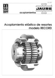
couplings<br />
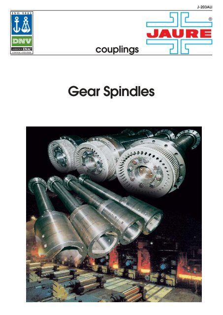
<strong>Gear</strong> <strong>Spindles</strong>
®<br />
<strong>Gear</strong> <strong>Spindles</strong><br />
Index<br />
• INTRODUCTION<br />
2<br />
Introduction<br />
• GEAR SPINDLES DESCRIPTION<br />
• PRODUCT CONCEPT<br />
• GEAR TOOTH DESIGN<br />
3<br />
4<br />
5<br />
• GEAR TOOTH MATERIALS<br />
AND HEAT TREATMENTS<br />
6<br />
• GEAR SIZE SELECTION<br />
• STANDARD DESIGNS<br />
• SPECIAL DESIGNS<br />
• SPINDLE ACCESORIES<br />
7<br />
9<br />
10<br />
12<br />
• SPINDLE MAINTENANCE<br />
AND LUBRICATION INSTRUCTIONS<br />
15<br />
• PROBLE<strong>MS</strong> AND CAUSES<br />
16<br />
• AFTER SALE AND<br />
RECONDITIONING SERVICES<br />
17<br />
Manufacturing plant in Zizurkil.<br />
• JAURE SUPPLYING PROGRAM<br />
• STEEL/ALUMINIUM MILLS<br />
APPLICATION LIST<br />
• APPLICATIONS<br />
• SELECTION DATA REQUIRED<br />
18<br />
19<br />
20<br />
22<br />
JAURE’s competence in power transmission<br />
system, is based on more than<br />
40 years experience in the development<br />
and manufacturing of couplings and<br />
power transmission elements.<br />
This is particularly testified by the most<br />
extensive supply of the gear couplings<br />
and spindles all over the world, being<br />
one of the world’s leaders in the fields<br />
of power transmission.<br />
<strong>Gear</strong> spindles are designed according<br />
to customers specifications, resulting in<br />
most of the cases special solutions.<br />
JAURE Engineering Department closely<br />
cooperates with customer’s engineers<br />
to create the best product for their<br />
needs.<br />
Rolling mill couplings that connect the<br />
drives and the rolls were often taken for<br />
granted. However, market demand for<br />
greater productivity and improved quality<br />
of rolled products, has driven the<br />
design and manufacture of equipment<br />
to accommodate high operating speeds,<br />
torques and misalignments with<br />
minimum maintenance.<br />
<strong>Gear</strong> spindles are a critical component<br />
of the drive train. Strip quality and<br />
thickness control can be influenced by<br />
the performance of the drive spindles.<br />
The modern and efficient gear type<br />
spindle, requires less maintenance and<br />
is much more economical than its predecessors.<br />
<strong>Gear</strong> spindles provide cons-<br />
tant angular velocity at misalignment<br />
angles, which ensures even transmission<br />
of power. This results in uniform<br />
sizes and improved surface quality of<br />
rolled products.<br />
In addition, the inherent dynamic<br />
balance characteristics of gear type flexible<br />
spindles minimize vibration, thus<br />
increasing the operating life of bearings,<br />
gears, and other components of<br />
the drive train.<br />
Computer–aided designs and the latest<br />
manufacturing CNC machines and testing<br />
equipment, ensure that our products<br />
always reflect the state of the art<br />
of drive components. Furthermore<br />
research and development, including<br />
Finite Element Analysis and solid<br />
modelling design methods assure our<br />
customers that their equipment will be<br />
optimized by their application.<br />
The design, manufacturing and sales of<br />
all of our gear couplings and drive components<br />
are integrated into our Quality<br />
System, according to UNE-EN-ISO<br />
9001. This Quality Policy covers all the<br />
different departments at JAURE.<br />
2
®<br />
<strong>Gear</strong> <strong>Spindles</strong><br />
<strong>Gear</strong> spindles description<br />
JAURE gear spindles are specially<br />
designed for those applications where<br />
driving and driven components are<br />
necessarily misaligned and where service<br />
dictates a changeable amount of<br />
misalignment.<br />
<strong>Gear</strong> spindles more common application<br />
is for ferrous and non ferrous<br />
rolling mills drive, where technology is<br />
in continuous development to achieve<br />
a higher product quality with lower and<br />
maintenance costs.<br />
Complete wire mill spindles.<br />
<strong>Gear</strong> spindles are critical components<br />
of the drive train and for this reason,<br />
JAURE to meet the demands of the<br />
most up-date mill equipment, designed<br />
his gear spindles which ensure performances,<br />
operating efficiency, less and<br />
easier maintenance. All the above<br />
advantages have been realized by<br />
developing teeth profile, surface heat<br />
treatment, materials quality and seals.<br />
Hot strip mill spindles.<br />
Steckel mill spindles.<br />
Telescopic quick disengaging spindles.<br />
To accommodate load and no load<br />
misalignment with minimum backlash<br />
is necessary to crown the flanks and the<br />
tips of the hub teeth. Teeth are also<br />
designed to allow higher no load angle<br />
to easy roll change.<br />
<strong>Spindles</strong> with fully crowned gear teeth<br />
offer operational benefits of maximum<br />
load carrying capacity with minimum<br />
size, maximum reliability and long life.<br />
Materials used in the production of<br />
spindle gear elements, include both<br />
medium carbon and forged alloy steels.<br />
The material and heat treatment combinations<br />
commonly used for spindles<br />
applications are shown in page 6.<br />
A vital aspect having a direct affect on<br />
spindles life and performances, is the<br />
provision of quality seals for efficient<br />
retention of the gear lubricant for exclusion<br />
external contaminates.<br />
Hot strip mill spindles.<br />
3
®<br />
<strong>Gear</strong> <strong>Spindles</strong><br />
Product Description<br />
Modern Rolling mills and revamping of<br />
old mills, require or are implementing<br />
new developments as: new machine<br />
design concepts, better metalurgical<br />
practices, as well as the application of<br />
process control and automation.<br />
Consequently, mechanical components<br />
including gear spindles are becoming a<br />
critical component of the drive train.<br />
To be able to transmit large torques at<br />
large misalignment, spindle gear couplings<br />
use fewer teeth than conventional<br />
gear couplings, high-strength alloyed<br />
steels, and surface hardening : either<br />
nitriding or carburizing. This is the<br />
case, for instance, in hot and cold<br />
rolling mills, continuos casting installations,<br />
straightening presses, rotary furnaces,<br />
etc.<br />
Each Jaure mill spindle is custom<br />
designed for a particular application.<br />
Torque amplification factors (TAF) are<br />
also considered when designing the<br />
spindle and all the effort is done at<br />
design stage to decrease the stresses<br />
on the gear mesh. The gear tooth profile<br />
is specially designed to optimize the<br />
load capability for each single application.<br />
Furthermore optimal design features<br />
and custom modifications are reviewed<br />
in our application analysis to ensure<br />
maximum service life with minimum<br />
downtime.<br />
Because of the high contact pressures<br />
and the high sliding velocities between<br />
the teeth , the lubricant are greases<br />
with a large amount of anti-wear additives.<br />
Special sealing system avoids<br />
overflow of lubricant and keeps contamination<br />
out of the grease chamber.<br />
Special attention is given to the materials<br />
and heat treatment used in each<br />
application in order to maximize the<br />
spindle life and reliability. Furthermore<br />
Jaure employs modern CNC manufacturing<br />
in order to ensure high accuracy<br />
and even distribution of the loads.<br />
PRODUCT DESCRIPTION<br />
4
®<br />
<strong>Gear</strong> <strong>Spindles</strong><br />
<strong>Gear</strong> tooth design<br />
A gear coupling is one of the simplest<br />
and most common types in use today. It<br />
is also one of the most difficult to<br />
design and evaluate, because of the<br />
number of variables that can affect its<br />
successful operation. Some of these<br />
variables are:<br />
to maximise the working area of the<br />
tooth reducing the Hertz contact stresses.<br />
1) Tooth design<br />
2) Material<br />
3) Lubrication<br />
The main concept of the gear tooth<br />
design, is optimisation of the tooth geometry<br />
to obtain a higher percent of<br />
teeth in contact at the coupling operation<br />
conditions. In order to perform this<br />
optimisation, is very important to<br />
understand the variables that effect the<br />
actual percent of teeth in contact:<br />
Misalignment Angle<br />
Theoretically, there are only two teeth<br />
in contact when misalignment is present<br />
and no load is applied. There must<br />
be a load applied to obtain contact of<br />
more than two teeth. The degree of<br />
misalignment partly determines the<br />
number of teeth in contact for a given<br />
amount of torque. The lower the angle,<br />
the more teeth in contact and greater<br />
the torque capacity.<br />
Flank curvature<br />
This is the main contributor besides the<br />
misalignment angle in determining the<br />
gap between each tooth set. An optimized<br />
flank curvature will produce minimal<br />
gaps between each tooth set while<br />
maintaining an acceptable compressive<br />
stress. Proper flank crowning reduces<br />
contact stress, prevents tooth end bending<br />
and increases the contact area by<br />
moving the load closer to the centre of<br />
the tooth. JAURE can also design a<br />
compound curvature on the tooth flank<br />
Tooth Loading<br />
There are three basic loading conditions<br />
which can contribute to tooth failure:<br />
- Hertz or compressive<br />
stress<br />
- Bending stress<br />
- Contact pressure/sliding<br />
velocity component<br />
All of these variables<br />
and different variables<br />
must be considered in<br />
the design of a gear<br />
spindle. JAURE’s Engineering<br />
Department designs the spindles according<br />
to the misalignment angle and<br />
each type of tooth loading and misalignment<br />
angle, selecting the right<br />
material and heat treatment with the<br />
right design of the tooth, to suit your<br />
application based on over 40 years of<br />
experience in spindle design.<br />
5
®<br />
<strong>Gear</strong> <strong>Spindles</strong><br />
<strong>Gear</strong> tooth materials and heat treatments<br />
Materials used by JAURE in the production<br />
of gear spindle components,<br />
include a proper combination of steel<br />
and heat treatment, depending on the<br />
stressing level and the required operating<br />
life. The best heat treatment for a<br />
coupling gear tooth gives the correct<br />
combination of core hardness versus<br />
case depth and hardness be used. For<br />
maximum strength and durability, its<br />
desirable to harden selected outer surfaces<br />
of spindles parts while leaving the<br />
inner cores ductile for shock resistance.<br />
Several heat treatment methods are<br />
available for case hardening the gear<br />
tooth components including nitriding,<br />
induction hardening and carburizing.<br />
The selections of a proper combination<br />
of steel and heat treatment, depending<br />
on the stressing level and the required<br />
operating life, are:<br />
• NA Heat treated nitrided alloy steel.<br />
This is for medium torque, high angle<br />
and high speed applications. Nitriding<br />
is also preferred for high temperature<br />
and high speeds applications where it<br />
is more durable than other forms of<br />
hardening.<br />
• NHA Heat treated nitrided alloy highstrength<br />
steel. For medium to high<br />
torques.<br />
• CHA Heat treated and carburized alloy<br />
high-strength steel. The carburizing<br />
Carburized coupling box.<br />
process imparts a hard, deep case<br />
over a ductile and shock resistant core<br />
to resist wear and abrasion. Mainly<br />
used in high torque applications.<br />
Nitrided hubs.<br />
6
®<br />
<strong>Gear</strong> <strong>Spindles</strong><br />
<strong>Gear</strong> size selection<br />
1) Compute torque to be transmitted, increased it multiplying by service factor SF<br />
and torque factor KA:<br />
where:<br />
Pa= Absorbed power [kW]<br />
n= RPM<br />
T =<br />
P a • 9,55<br />
n<br />
• SF • KA (kNm)<br />
4) Select spindle size from engineering<br />
data on page 8. The torque capacity<br />
varies with spindle size and gearing<br />
material; chose a spindle size and a<br />
gearing material with:<br />
Tnom > T<br />
5) Besides check that:<br />
Tmax > T x TAF<br />
2) Select the service factor SF from table 1.<br />
APPLICATION<br />
Auxiliary Mill Equipment<br />
Wire, Small Bar and Rod Mills: All Stands<br />
Medium Bar and Section Mills: Finishing Stands<br />
Cold Mills: Non-Reversing<br />
Straighteners<br />
Medium Bar and Section Mills: Roughing Stands<br />
Large Bar and Section Mill: Finishing Sands<br />
Cold Mills: Reversing<br />
Hot Strip Mills: Non-Reversing Finishing Stands.<br />
Large Bar and Section Mills: Non-Reversing Roughing Stands<br />
Tube Mill Main Drive<br />
Hot Strip Mills: Non-Reversing Roughing Stands<br />
Edgers, Non-Reversing<br />
Hot Strip Mills: Reversing Roughing Stands<br />
Large Bar and Section Mills: Reversing Roughing Stands<br />
Edgers,Reversing.<br />
Steckel Mills<br />
Reversing Slab, Plate and Blooming Mills<br />
Table 1<br />
3) Compute Torque factor KA, depending by working angle<br />
shown on graphic 1:<br />
2,4<br />
2<br />
1,6<br />
1,2<br />
0,8<br />
0,4<br />
0<br />
0,5 1 1,5 2 2,5 3<br />
Working angle(deg)<br />
SF<br />
1.5<br />
1.75<br />
2.0<br />
2.5<br />
2.75<br />
3.0<br />
2,5<br />
2<br />
1,5<br />
1<br />
0,5<br />
Where:<br />
Tmax= Peak Torque (KNm)<br />
TAF= Torque amplification factor<br />
6) Check the maximum speed n, has to<br />
be equal or lower than the selected<br />
size coupling maximum speed multiplied<br />
by the speed factor KS, depending<br />
by operating misalignment,<br />
shown on graphic 2:<br />
n ≤ K s • n max<br />
0<br />
0,5 1 1,5 2 2,5 3<br />
Graphic 2<br />
Working angle(deg)<br />
• For angles greater than 3º consult JAURE<br />
CONVERSION TABLE<br />
1 mm = 0,0394 inch<br />
1 inch = 25,4 mm<br />
1 m = 39,4 inch = 3.283 ft<br />
1 Kg = 2,2046 ibs (weight)<br />
1 ib (wt) = 0,4536 Kg<br />
1 N = 0,2248 ibs (force)<br />
1 ib (f) = 4,4482 N<br />
1 Nm = 0,7376 ib-ft<br />
1 ib-ft = 1,3558 Nm<br />
1 Kgm = 23,76 ib-ft<br />
1ib-ft = 0,1382 kgm<br />
1 KW = 1,34 HP<br />
1 HP = 0,746 kw<br />
Graphic 1<br />
7
®<br />
<strong>Gear</strong> <strong>Spindles</strong><br />
<strong>Gear</strong> size selection<br />
Heat treated nitr. Alloy steel<br />
(NA)<br />
Heat treat. Nitr. Alloy<br />
high-strength steel (NHA)<br />
Heat treat. Carb. Alloy (1)<br />
high-strength steel (CHA)<br />
SIZE<br />
Nominal Torque<br />
Peak Torque Max speed Nominal Torque Peak Torque Max speed Nominal Torque Peak Torque<br />
Max speed<br />
T nom<br />
(KNm)<br />
T max<br />
(KNm)<br />
n max<br />
(rpm)<br />
T nom<br />
(KNm)<br />
T max<br />
(KNm)<br />
T nom<br />
(KNm)<br />
T max<br />
(KNm)<br />
AL-100 5 13 1.970 7 18 2.955 11 28 2.522<br />
AL-115 7 18 1.860 10 25 2.790 15 37 2.381<br />
AL-130 9 23 1.790 13 32 2.685 20 50 2.291<br />
AL-150 16 40 1.670 23 57 2.505 36 90 2.138<br />
AL-180 25 62 1.560 36 90 2.340 56 140 1.997<br />
AL-200 40 100 1.430 58 145 2.145 90 225 1.830<br />
AL-250 65 162 1.320 94 235 1.980 146 365 1.690<br />
AL-275 95 237 1.200 137 342 1.800 213 532 1.536<br />
AL-300 130 325 1.080 188 470 1.620 292 730 1.382<br />
AL-330 185 462 960 268 670 1.440 416 1.040 1.229<br />
AL-360 220 550 860 319 797 1.290 495 1.237 1.101<br />
AL-400 345 862 750 500 1.250 1.125 776 1.940 960<br />
AL-440 410 1.025 650 594 1.485 975 922 2.305 832<br />
AL-480 610 1.525 610 884 2.210 915 1.372 3.430 781<br />
AL-520 780 1.950 525 1.131 2.827 788 1.755 4.387 672<br />
AL-550 850 2.125 510 1.232 3.080 765 1.912 4.780 653<br />
AL-590 1.120 2.800 475 1.624 4.060 713 2.520 6.300 608<br />
AL-640 1.300 3.250 430 1.885 4.712 645 2.925 7.312 550<br />
AL-700 1.750 4.375 390 2.537 6.342 585 3.937 9.842 499<br />
AL-760 2.000 5.000 350 2.900 7.250 525 4.500 11.250 448<br />
AL-830 2.800 7.000 310 4.060 10.150 465 6.300 15.750 397<br />
AL-880 3.100 7.750 290 4.495 11.237 435 6.975 17.437 371<br />
AL-950 3.500 8.750 270 5.075 12.687 405 7.875 19.687 346<br />
AL-1000 3.800 9.500 250 5.510 13.775 375 8.550 21.375 320<br />
AL-1100 4.100 10,250 200 5.945 14.862 300 9.225 23.062 256<br />
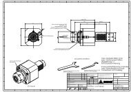
(1) If AL-S design is required the distance “x” will vary from the one stated in the catalog. Please consult Jaure.<br />
n max<br />
(rpm)<br />
n max<br />
(rpm)<br />
SIZE<br />
D<br />
(mm)<br />
D1<br />
(mm)<br />
A<br />
(mm)<br />
Dimensions<br />
A1<br />
(mm)<br />
B<br />
(mm)<br />
B1<br />
(mm)<br />
X<br />
(mm)<br />
Maximum(2)<br />
bores<br />
d max<br />
(mm)<br />
d1 max<br />
(mm)<br />
Coupl.<br />
End A<br />
Weight (Kg.)<br />
Coupl.<br />
End B<br />
Coupl.<br />
Shaft (3)<br />
AL-100 100 150 75 110 75 110 35 70 105 4 14 4<br />
AL-115 115 155 85 115 85 115 40 80 110 7 15 5<br />
AL-130 130 165 100 125 100 125 45 90 120 9 18 6<br />
AL-150 150 175 110 130 110 130 50 105 125 14 22 8<br />
AL-180 180 200 135 150 135 150 55 130 145 24 32 12<br />
AL-200 200 220 150 165 150 165 60 145 160 32 42 14<br />
AL-250 250 280 190 210 190 210 70 180 200 60 82 23<br />
AL-275 275 305 205 230 205 230 75 195 220 78 105 28<br />
AL-300 300 320 225 240 225 240 80 215 230 100 120 33<br />
AL-330 330 350 245 260 245 260 85 235 250 131 154 40<br />
AL-360 360 385 270 290 270 290 95 260 275 167 202 48<br />
AL-400 400 425 300 320 300 320 105 285 305 225 267 59<br />
AL-440 440 470 330 350 330 350 115 315 335 295 355 72<br />
AL-480 480 510 360 380 360 380 125 345 365 377 447 86<br />
AL-520 520 550 390 410 390 410 135 370 395 472 554 101<br />
AL-550 550 585 410 440 410 440 145 390 420 554 659 113<br />
AL-590 590 630 440 470 440 470 155 420 450 675 812 131<br />
AL-640 640 680 480 510 480 510 165 455 485 849 1.008 154<br />
AL-700 700 745 520 555 520 555 170 500 535 1.094 1.303 185<br />
AL-760 760 810 570 605 570 605 175 545 580 1.380 1.653 219<br />
AL-830 830 885 620 660 620 660 180 590 630 1.771 2.123 262<br />
AL-880 880 935 660 700 660 700 185 630 670 2.089 2.479 295<br />
AL-950 950 1.010 710 755 710 755 200 680 720 2.593 3.083 345<br />
AL-1000 1.000 1.065 745 795 745 795 215 715 760 2.998 3.582 383<br />
AL-1100 1.100 1.170 820 875 820 875 225 785 835 3.924 4.674 465<br />
NOTES:<br />
(1) This design is only valid with an intermediate sleeve. See page 4.<br />
(2) Dimensions dmax and d1max are valid for shaped bore on roll end side and finished bore and keyway UNI 6604-DIN 6885 on drive end side.<br />
(3) Shaft’s weight is for a 100 mm length.<br />
8
®<br />
<strong>Gear</strong> <strong>Spindles</strong><br />
Standard designs<br />
D<br />
d<br />
d<br />
D<br />
A<br />
X<br />
DBGM<br />
X<br />
B<br />
AL-S<br />
DBSE<br />
D<br />
d<br />
d1<br />
D1<br />
A<br />
X<br />
DBGM<br />
X<br />
B1<br />
AL-SD<br />
DBSE<br />
D1<br />
d1<br />
d1<br />
D1<br />
A1<br />
X<br />
DBGM<br />
X<br />
B1<br />
AL-D<br />
DBSE<br />
9
®<br />
<strong>Gear</strong> <strong>Spindles</strong><br />
Special designs<br />
Quick disenganging<br />
Telescopic type<br />
AL-SBR<br />
AL-S-SAFESET ® 1<br />
10 SAFESET ® is a trade mark from VOITH
®<br />
<strong>Gear</strong> <strong>Spindles</strong><br />
Special designs<br />
AL-S-SAFESET ® 2<br />
AL-ST<br />
"A"<br />
"B"<br />
"B"<br />
"A"<br />
Continous lubrication<br />
Oil-lubrication<br />
SECTION "A"-"A"<br />
SECTION "B"-"B"<br />
LUBE RING<br />
OIL CATCH BOX<br />
SAFESET ® is a trade mark from VOITH<br />
11
®<br />
<strong>Gear</strong> <strong>Spindles</strong><br />
Spindle accesories<br />
1) A serious roll entry problem is caused<br />
by drooping roll sleeve when<br />
spindle support is located under the<br />
shaft. This can be overcome with the<br />
use of a spring loaded sleeve aligning<br />
device, fig 1, which holds the roll sleeve<br />
in line with the spindle shaft when<br />
the roll is removed, and maintains it<br />
aligned and ready for re-entry of new<br />
roll.<br />
2) Special seal, which assures a complete<br />
grease unleackage under the<br />
worst working conditions is shown in<br />
fig.2:<br />
3) Numerous means of roll end connection<br />
are available. The simplest, provided<br />
for bases spindles, is a shaped bore<br />
in the spindle sleeve having the same<br />
configuration as the roll end with minimum<br />
clearance to allow roll removal<br />
and re-entry.<br />
A similar but preferable connection is<br />
the use of flat, round or piloting ring<br />
inserts, fig 3. and 4, which are replaceable<br />
when the inevitable wear does<br />
occur. These keys and piloting rings are<br />
made of heat-treated alloy steel for<br />
maximum usable life.<br />
4) Automatic tapered keys, fig.5 are the<br />
best device for tight sleeve-to-roll connection<br />
with ease of roll removal and<br />
replacement. It consists of a pair diametrically<br />
opposed tapered keys which<br />
are snugly scated against the spade<br />
flats when a roll is inserted, but which<br />
follow the roll neck for a limited distance<br />
during removal and produce ample<br />
clearance across the flats for roll removal<br />
and re-entry.<br />
5) Flat journal profiles for spindle sleeves<br />
on the end roller.<br />
Fig. 1 Shock absorber unit<br />
Fig. 2 Special seal<br />
12
®<br />
<strong>Gear</strong> <strong>Spindles</strong><br />
Spindle accesories<br />
Fig. 3 Replaceable wear flats<br />
Fig. 4 Centering rings<br />
Fig. 5 Automatic locking key<br />
13
®<br />
<strong>Gear</strong> <strong>Spindles</strong><br />
Spindle accesories<br />
Fig.6<br />
Slotted profile for flat journals, used<br />
preferably in bores that are large in<br />
relationship to outer diameter of sleeve.<br />
Slanted surfaces around diameter<br />
centre roller journal exactly. Bore can<br />
be given optional special treatment to<br />
increase its surface strength and wear<br />
resistance.<br />
Fig. 6 Slotted profile<br />
Fig.7<br />
Flat journal profile with inserted, hardened<br />
and ground steel jaws. High wear<br />
resistance even despite angular vibrations<br />
or thrusts that would otherwise<br />
damage coupling sleeve during a roller<br />
change. Easy to replace steel jaws if<br />
necessary. Cost-efficient stock keeping.<br />
Fig. 7 Flat journal profile with steel jaws<br />
Fig.8<br />
Flat journal profile with inserted jaws<br />
and guide profiles made of hard plastic.<br />
Good protection against formation of<br />
frictional corrosion when aggressive<br />
cooling agents are used. Cost-efficient<br />
stock keeping since only plastic parts<br />
have to be kept. Easy to replace parts<br />
subject to wear.<br />
Fig. 8 Flat jounal profile with plastic jaws<br />
14
®<br />
<strong>Gear</strong> <strong>Spindles</strong><br />
Spindle maintenance and lubrication instructions<br />
The gear spindles must be lubricated in<br />
site with rolls in working position. If the<br />
spindle is lubricated with the rolls<br />
removed an excess of grease will come<br />
out once the roll is in. This pump of<br />
excess of grease can damage the seals.<br />
SPINDLE COUPLING LUBRICATION.<br />
If an annormally short life of the spindles<br />
is observed the first thing to check<br />
is the lubricant. A lack of proper lubrication<br />
will generate heat and will not<br />
dissipate it , therefore the spindle will<br />
fail by overheating.<br />
a) Recommended greases.<br />
<strong>Gear</strong> spindle couplings require very<br />
special lubricants with highly refined<br />
base oils that have high viscosity indexes,<br />
excellent extreme pressure qualities,<br />
water resistance and adhesiveness.<br />
The lubricant used should provide<br />
a low friction film between the working<br />
surfaces to reduce the possibility<br />
of wear. The lubricant should also have<br />
extreme pressure capability and good<br />
capacity for dissipating the heat generated<br />
from sliding and rolling action of<br />
mating gear teeth.<br />
Grease technical features 1<br />
NLGI Grade Between 1 and 2<br />
Thickener type Lithium complex<br />
Dropping point 175÷240ºC<br />
Oil<br />
Synthetic<br />
Oil viscosity at 40ºC Higher than 800 Cst<br />
Oil viscosity at 100ºC Higher than 45 Cst<br />
MoS2 5-10%<br />
EP additive 2 Required<br />
Timken EP Test Higher than 30 Kg<br />
Oxidation inhibitors Required<br />
Soap percentage 5-10 %<br />
1) For speeds above 1000 rpm consult our Technical Dep.<br />
In this case the grease should have good centrifugal separation<br />
resistance.<br />
2) Verify that EP grease used environmentally friendly with<br />
lack of lead and chlorine.<br />
Examples of greases that comply with<br />
the above features are:<br />
• BESLUX BMX H-1 from BRUGAROLAS<br />
• MOBILUX EP-111 from MOBIL<br />
• MULTIFAK EP-2 from TEXACO<br />
• KLUBERLUB BE 41-1501 from KLUBER<br />
b) Method of lubrication.<br />
When installing or reinstalling the<br />
spindle, be sure also to hand-pack the<br />
teeth with grease prior to greasing by<br />
normal methods, to ensure that the<br />
teeth will not run dry for the first few<br />
minutes of operation until the lubricant<br />
works its way to the gear mesh.<br />
In order to proceed with greasing ,<br />
remove one of the vent plugs and<br />
pump grease using one of the grease<br />
nipples placed in the spindle shaft or<br />
adapters. The lubrication would be<br />
completed when the grease comes out<br />
of the vent hole continuously. Do not<br />
forget to screw back the vent plugs<br />
since the spindle coupling can loose all<br />
the grease.<br />
Always lubricate at both sides of the<br />
spindle.<br />
c) Lubrication frequency.<br />
-At start up, lubricate after few hours<br />
of operation, check and grease if<br />
necessary.<br />
- At break in period, for the first<br />
month of operation lubricate every 3<br />
days.<br />
- In normal operation, lubricate every<br />
15 days. For applications involving<br />
reversing, sever shock or high wisalignment,<br />
lubricate at least weekly.<br />
If excessive rolling fluid or contaminants<br />
are present, ambient temperatures<br />
are a problem, or excesive running<br />
temperatures on the gear mesh (>70ºC),<br />
more frequent lubrication may be<br />
necessary.<br />
For longer lubrication periods, please<br />
ask our technical departament.<br />
When a telescopic shaft exists, use a<br />
grease nipple on the shaft in order to<br />
lubricate the spline. The spline should<br />
be lubricated every 2/4 months depending<br />
on the shifting.<br />
15
®<br />
<strong>Gear</strong> <strong>Spindles</strong><br />
Spindle maintenance and lubrication instructions<br />
SPINDLE COUPLING MAINTENANCE<br />
Scheduled inspections should be performed<br />
in order to achieve a long<br />
spindle life and proper operation.<br />
These first inspections are advised to<br />
be:<br />
1) after 1-2 weeks.<br />
2) after 4-6 weeks.<br />
3) after 8-10 weeks.<br />
Later on, the inspections are to be<br />
carried out every 5-6 months or every<br />
4000-6000 hours, at least once a year.<br />
During these inspections, the spindle<br />
should be thoroughly cleaned and the<br />
following checking have to be performed<br />
:<br />
a) Flange bolts tightening.<br />
b) <strong>Gear</strong> teeth wear control.<br />
c) Noise and vibrations. In case of anomalous<br />
noise/ or vibrations , check<br />
immediately the cause.<br />
d) Be sure that no excessive grease leakage<br />
is present, caused by seal wear,<br />
grease nipple and plugs failure.<br />
Damaged components should be replaced.<br />
If toothed components are not<br />
replaced it is advantageous to re-engage<br />
the teeth in the same mesh in which<br />
they were running. Top and bottom<br />
spindles should be interchanged to<br />
equalize tooth wear .<br />
Always maintain an inventory of spare<br />
parts sufficient to insure continuity of<br />
plant operation.<br />
All rotating parts must be guarded to<br />
prevent accidents according to national<br />
and local safety rules.<br />
Problems and causes<br />
Spindle special seal for harsh environments.<br />
1. Anomalous gearing wear<br />
• Lubricant deficiency due to:<br />
- Unproper lubrication schedules<br />
- Seals wear or failure<br />
- Grease plugs leakage<br />
- Inadequate quantity of grease<br />
• Operation under conditions different<br />
from the original project.<br />
• Excessive backlash between roll neck<br />
and sleeve bore<br />
2. Teeth Failure<br />
• Excessive misalignment<br />
• Overloads<br />
• Excessive backlash<br />
3. Flange bolts loosening<br />
and failure<br />
• Flange and shaft mechanical contact<br />
• Unproper bolts tightening torques<br />
• Excessive spindle vibrations<br />
4. Roll sleeve bore anomalous wear<br />
• Inadequate lubrication<br />
• Sleeve overheating in operation causing<br />
a reduction of bore surface hardness<br />
• High spindle vibrations<br />
• Worn out or excessively rough roll<br />
neck surfaces<br />
5. Vibrations<br />
• Roll sleeve bore excessive wear<br />
• Flange bolts loosening or failure<br />
• Excessive gearing wear<br />
16
®<br />
<strong>Gear</strong> <strong>Spindles</strong><br />
After sales and reconditioning services<br />
Repair and maintenance program<br />
At the urging of gear spindle users,<br />
JAURE is engaged in the repair of the<br />
gear-type spindle couplings for over 40<br />
years.<br />
The program we established allows us<br />
to provide our customers with a quick<br />
turnaround( short time from receiving<br />
the coupling to delivery of the repaired<br />
unit), and at reduced costs( as compared<br />
with buying a new coupling).<br />
Additionally, in analizing the damaged<br />
couplings sent to us, we are able to<br />
advice our customers on improved<br />
maintenance procedures, so that the<br />
repaired units most often have a longer<br />
service life than the original coupling.<br />
Analysis of the received coupling.<br />
Our analysis has three aspects:<br />
1) We observe the unit’s damaged<br />
parts. For instance: Do the teeth<br />
show excessive misalignment? Are<br />
the seals showing signs of leakage?<br />
Is the lubricant contaminated or was<br />
it subjected to high temperatures?<br />
2) If in doubt of material quality, we cut<br />
samples of the damaged components<br />
and send them for metallurgical<br />
analysis.<br />
3) We discuss the application with the<br />
customer’s maintenance personnel,<br />
and try to improve the maintenance.<br />
In some cases, through these discussions<br />
we find out that the coupling is<br />
not adequate for the application.<br />
Our technicians have many years of<br />
experience in this field, and our engineers<br />
are often consulted in deciding<br />
which repairs are necessary.<br />
A complete report is drafted of the technicians`<br />
findings, and a list of the required<br />
repairs( including prices) is made<br />
and sent to our customer for approval.<br />
No work is done without customer consent.<br />
Actual repair procedure<br />
Evidently, the most costly components<br />
are the hubs and the intermediate gear<br />
rings. All effort is made to salvage<br />
these components, if is possible. In<br />
many cases damaged teeth can restored<br />
to almost original condition, and<br />
parts can be reused. If repairing these<br />
components would reduce the quality<br />
of the coupling, then we recommend<br />
their replacement. In the case of very<br />
old couplings, we are able to offer<br />
replacement components made of better<br />
and newer materials, or better heat<br />
treatments, thus improving the life<br />
expectancy of the repaired coupling.<br />
Some of the components are routinely<br />
replaced; this is always the case with<br />
the square keys, and any bolts or nuts<br />
that have worn or damaged threads.<br />
Also, all seals are replaced, so that the<br />
lubricant is held within the coupling,<br />
and water and or dirt is prevented to<br />
enter the coupling.<br />
Inventory program of replacement<br />
parts<br />
JAURE keeps a record of all the repairs<br />
since the coupling repair program is<br />
implemented. This records are computerized,<br />
and we can now predict which<br />
parts will be in demand. Therefore,<br />
JAURE can establish in his warehouse<br />
a stock of parts most frequently required<br />
for repairs. We are thus able to offer<br />
a quick turnaround, as seldom do we<br />
need to manufacture parts from<br />
scratch, after the coupling is sent to us.<br />
With many of our repeat customers we<br />
establish a program frequency of<br />
repairs, so that we are able to stock special<br />
components even before we receive<br />
a coupling. Parts are replaced only if<br />
necessary.<br />
The advantages of JAURE`s repair<br />
program<br />
• JAURE will repair your coupling in the<br />
shortest time possible.<br />
• JAURE will repair your gear-type<br />
spindle coupling at lower cost than a<br />
new coupling.<br />
• JAURE will work with your maintenance<br />
department to increase expected<br />
life of repaired units.<br />
• JAURE technicians and engineers<br />
have a broad experience, both in<br />
manufacturing new spindle couplings,<br />
and in the repair of damaged<br />
gear-type spindle couplings.<br />
You can rely on JAURE to have the best<br />
job done, at a competitive price.<br />
17
®<br />
<strong>Gear</strong> <strong>Spindles</strong><br />
JAURE Supplying Program for steel/aluminium mills<br />
GEAR COUPLING<br />
OR<br />
ELASTOMERIC COUPLING<br />
GEAR COUPLING<br />
SPINDLE<br />
OR<br />
U-JOINT<br />
MOTOR<br />
GEAR BOX<br />
PINION<br />
STAND<br />
WORK ROLLS<br />
MT Crowned Tooth <strong>Gear</strong> Coupling.<br />
(Nominal Torque up to 7.000 kNm)<br />
MTX - 800 Spacer <strong>Gear</strong> Spacer Coupling.<br />
For Steckel Mill Main Drive<br />
AL <strong>Gear</strong> Spindle.<br />
(Nominal Torque up to 6500 kNm)<br />
MMG Elastomeric Coupling.<br />
(Nominal Torque up to 1600 kNm)<br />
Safety element (1)<br />
JG Universal Joint.<br />
(Nominal Torque up to 3500 kNm)<br />
18<br />
(1) Safeset® is a trade mark from Voith.
®<br />
<strong>Gear</strong> <strong>Spindles</strong><br />
Steel/Aluminium mills application list<br />
Mayor Applications <strong>Gear</strong> Spindle Universal Joint Elastomeric (1) <strong>Gear</strong> Coupling Disc Coupling<br />
Coupling (Lamidisc ® )<br />
Bar/Rod Mill main drive ✔ ✔ ✔ ✔<br />
Wire mill ✔ ✔ ✔ ✔<br />
Coilers ✔ ✔<br />
Pinch rolls ✔ ✔ ✔ ✔<br />
Straighteners ✔ ✔ ✔<br />
Cold mill main drive ✔ ✔ ✔<br />
Hot strip mill main drive ✔ ✔ ✔ ✔<br />
Plate/Steckel mill main drive ✔ ✔ ✔ ✔<br />
Edger drives ✔ ✔ ✔ ✔<br />
Tube mill main drive ✔ ✔ ✔ ✔<br />
Runout/Entry/Exit table drives ✔ ✔<br />
Cranes ✔ ✔ ✔<br />
Casters ✔ ✔ ✔<br />
(1) Elastomeric couplings in silicon plexing element also available.<br />
19
®<br />
<strong>Gear</strong> <strong>Spindles</strong><br />
Applications and Manufacturing<br />
Hot mill spindle.<br />
Hot strip mill<br />
spindles with safeset ®<br />
Hot strip mill<br />
Cold rolling mill spindles.<br />
<strong>Spindles</strong> with shear pins<br />
Continuous lubricated spindle.<br />
20 SAFESET ® is a trade mark from VOITH<br />
Horizontal and Vertical Stands with<br />
JAURE <strong>Spindles</strong>
®<br />
<strong>Gear</strong> <strong>Spindles</strong><br />
Applications and Manufacturing<br />
Wire mill spindles<br />
MT-730 Main Drive <strong>Gear</strong> Coupling<br />
Coupling Box deburring<br />
Internal sleeve grinding.<br />
Steckel mill telescopic spindles<br />
Hot strip mill spindle at maintenance<br />
Main Drive <strong>Gear</strong> Coupling Pumping oil into a spindle with Safeset ®<br />
Skin Pass gear spindles<br />
SAFESET ® is a trade mark from VOITH<br />
21
®<br />
<strong>Gear</strong> <strong>Spindles</strong><br />
Selection data required<br />
Name<br />
Company<br />
Phone Fax E-mail<br />
Date<br />
Inquiry Number<br />
Mill Type<br />
Number of Stands<br />
Number of Required Assemblies<br />
Please include your comments:<br />
22
®<br />
<strong>Gear</strong> <strong>Spindles</strong><br />
Selection data required<br />
Please provide the following information in the boxes provided:<br />
3<br />
Requiered Service Factor<br />
7 Shaft Separation<br />
Min. and Max. if Axial<br />
( Travel is required )<br />
12<br />
13<br />
Min. Roll Diameter<br />
Max. Roll Diameter<br />
1 kW<br />
2 RPM<br />
Min.<br />
Max.<br />
Overload<br />
4<br />
Rating<br />
5<br />
Ratio<br />
6<br />
Shaft Centers<br />
8 Min. 9<br />
Max.<br />
Motor<br />
Reducer<br />
Pinion Stand<br />
12<br />
13<br />
Max. Angle-Operating<br />
Max. Angle-Roll Change<br />
Work Roll Centers<br />
Style I-Roll Neck<br />
A<br />
14<br />
Bore Requirements<br />
B<br />
D<br />
C<br />
Style Pinion Shaft Roll Neck<br />
E-Radius<br />
Style II-Pinion Shaft<br />
A<br />
Style II-Pinion<br />
B<br />
A<br />
B<br />
Engagement<br />
Length<br />
Key Width<br />
Engagement<br />
Length<br />
Flat Length<br />
C<br />
Key Depth<br />
Across Flats<br />
D<br />
C<br />
D<br />
Shaft Dia.<br />
Neck Dia.<br />
E-Radius<br />
E<br />
Radius<br />
Radius<br />
Please note any other mill characteristics such as:<br />
• Method of Roll Change<br />
• Drive Orientation (Vertical or Horizontal, etc)<br />
• Operating Environment<br />
• Unidirectional of Reversing Drive<br />
• Restrictions on Diameter<br />
• Any Other Pertinent Information<br />
®<br />
ISO 9001<br />
ACCREDITED BY<br />
CERTIFICATED FIRM<br />
Ernio bidea, s/n<br />
20150 ZIZURKIL (Guipúzcoa) SPAIN<br />
Phone: +34 943 69.00.54<br />
Fax: +34 943 69.02.95<br />
Fax Tech. Dept. +34 943 69.03.17<br />
Post address : P.O. Box, 47<br />
20150 VILLABONA (Guipúzcoa) SPAIN<br />
e-mail:sales.dep@jaure.com<br />
http://www.jaure.com<br />
23
®<br />
JAURE, S.A. - Couplings and transmission elements.<br />
MT crowned tooth gear coupling<br />
LAMIDISC ® all steel disc coupling<br />
Barrel coupling TCB ®/ TCB-s ®<br />
<strong>Gear</strong> spindles for rolling mills<br />
High speed disc coplings LAMIDISC ® HP<br />
Composite link coupling COMPOLINK ®<br />
RECORD flexible spring coupling<br />
JAUFLEX ® elastic coupling<br />
IXILFLEX ® link type elastic coupling<br />
®<br />
ISO 9001<br />
BIARRITZ<br />
mod.: JAU0124369B<br />
BILBAO<br />
SAN SEBASTIAN<br />
ACCREDITED BY<br />
CERTIFICATED FIRM<br />
JAURE, S.A.<br />
Ernio bidea, s/n - 20150 ZIZURKIL (Guipúzcoa) SPAIN<br />
Phone: +34 943 69.00.54 - Fax: +34 943 69.02.95<br />
Fax Tech. Dept.: +34 943 69.03.17<br />
Post address : P.O. Box, 47<br />
20150 VILLABONA (Guipúzcoa) SPAIN<br />
e-mail:info@jaure.com • http://www.jaure.com<br />
VITORIA<br />
VILLABONA<br />
ZIZURKIL TOLOSA<br />
PAMPLONA