Designing Quieter Fans for Turbo-Jet Engines - Ansys
Designing Quieter Fans for Turbo-Jet Engines - Ansys
Designing Quieter Fans for Turbo-Jet Engines - Ansys

Create successful ePaper yourself
Turn your PDF publications into a flip-book with our unique Google optimized e-Paper software.
25<br />
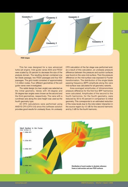
FEGV shapes<br />
This fan was designed <strong>for</strong> a new advanced<br />
turbo-jet engine. Inlet guide vanes (IGV) and FEGV<br />
were scaled by 20 percent to decrease the size of the<br />
analysis domain. The resulting domain contained one<br />
fan blade passage, two FEGV passages and four IGV<br />
passages. The grid model consisted of approximately<br />
1.5 million nodes. Four different geometries of the exit<br />
guide vanes were investigated.<br />
The radial design (no lean angle) was selected as<br />
the initial geometry. Vanes with 20-degree and<br />
30-degree lean angles were chosen as the second and<br />
the third geometries, respectively. The vane with a<br />
curvilinear axis along the vane height was used as the<br />
fourth geometry type.<br />
All CFD calculations were per<strong>for</strong>med using<br />
ANSYS CFX (CFX-5.6) since this software solution<br />
provides good results <strong>for</strong> unsteady flows. An unsteady<br />
CFD calculation of the fan stage was per<strong>for</strong>med and,<br />
as a result of this calculation, an unsteady pressure<br />
difference between the pressure and suction surfaces<br />
was found on the vane mid-surface. Then the pressure<br />
difference on the mid-surface was exposed to Fourier<br />
trans<strong>for</strong>mation. The distribution of the single blade<br />
passing frequency (BPF) amplitude along the vane<br />
mid-surface was calculated <strong>for</strong> all geometry variants.<br />
Area-averaged amplitudes of dimensionless<br />
pressure difference <strong>for</strong> the first four BPF harmonics<br />
were calculated. Amplitudes of the second to the<br />
fourth harmonics, <strong>for</strong> the fourth geometry, were<br />
reduced by 30 to 40 percent in comparison to initial<br />
geometry. This corresponds to an estimated reduction<br />
of the noise levels due to the rotor-stator interaction in<br />
the source region by 4.5 dB <strong>for</strong> the second harmonic<br />
and by 3 dB <strong>for</strong> the fourth harmonic.<br />
Distribution of mach number in absolute reference<br />
frame at mid-section and near FEGV surfaces<br />
www.ansys.com ANSYS Solutions | Volume 7, Issue 2 2006