Designing Quieter Fans for Turbo-Jet Engines - Ansys
Designing Quieter Fans for Turbo-Jet Engines - Ansys
Designing Quieter Fans for Turbo-Jet Engines - Ansys

Create successful ePaper yourself
Turn your PDF publications into a flip-book with our unique Google optimized e-Paper software.
CFD Update: What’s New in Computational Fluid Dynamics<br />
24<br />
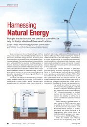
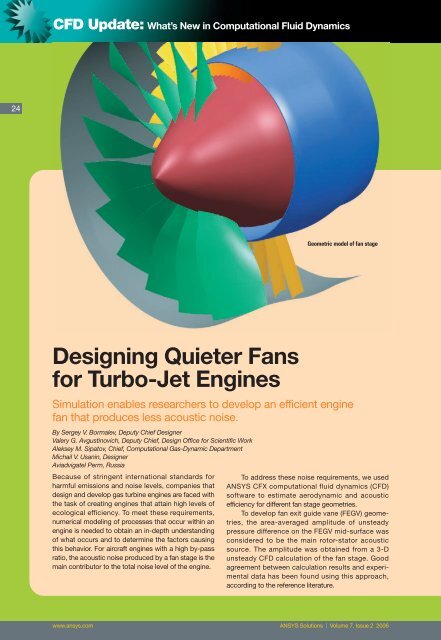
Geometric model of fan stage<br />
<strong>Designing</strong> <strong>Quieter</strong> <strong>Fans</strong><br />
<strong>for</strong> <strong>Turbo</strong>-<strong>Jet</strong> <strong>Engines</strong><br />
Simulation enables researchers to develop an efficient engine<br />
fan that produces less acoustic noise.<br />
By Sergey V. Bormalev, Deputy Chief Designer<br />
Valery G. Avgustinovich, Deputy Chief, Design Office <strong>for</strong> Scientific Work<br />
Aleksey M. Sipatov, Chief, Computational Gas-Dynamic Department<br />
Michail V. Usanin, Designer<br />
Aviadvigatel Perm, Russia<br />
Because of stringent international standards <strong>for</strong><br />
harmful emissions and noise levels, companies that<br />
design and develop gas turbine engines are faced with<br />
the task of creating engines that attain high levels of<br />
ecological efficiency. To meet these requirements,<br />
numerical modeling of processes that occur within an<br />
engine is needed to obtain an in-depth understanding<br />
of what occurs and to determine the factors causing<br />
this behavior. For aircraft engines with a high by-pass<br />
ratio, the acoustic noise produced by a fan stage is the<br />
main contributor to the total noise level of the engine.<br />
To address these noise requirements, we used<br />
ANSYS CFX computational fluid dynamics (CFD)<br />
software to estimate aerodynamic and acoustic<br />
efficiency <strong>for</strong> different fan stage geometries.<br />
To develop fan exit guide vane (FEGV) geometries,<br />
the area-averaged amplitude of unsteady<br />
pressure difference on the FEGV mid-surface was<br />
considered to be the main rotor-stator acoustic<br />
source. The amplitude was obtained from a 3-D<br />
unsteady CFD calculation of the fan stage. Good<br />
agreement between calculation results and experimental<br />
data has been found using this approach,<br />
according to the reference literature.<br />
www.ansys.com ANSYS Solutions | Volume 7, Issue 2 2006
25<br />
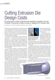
FEGV shapes<br />
This fan was designed <strong>for</strong> a new advanced<br />
turbo-jet engine. Inlet guide vanes (IGV) and FEGV<br />
were scaled by 20 percent to decrease the size of the<br />
analysis domain. The resulting domain contained one<br />
fan blade passage, two FEGV passages and four IGV<br />
passages. The grid model consisted of approximately<br />
1.5 million nodes. Four different geometries of the exit<br />
guide vanes were investigated.<br />
The radial design (no lean angle) was selected as<br />
the initial geometry. Vanes with 20-degree and<br />
30-degree lean angles were chosen as the second and<br />
the third geometries, respectively. The vane with a<br />
curvilinear axis along the vane height was used as the<br />
fourth geometry type.<br />
All CFD calculations were per<strong>for</strong>med using<br />
ANSYS CFX (CFX-5.6) since this software solution<br />
provides good results <strong>for</strong> unsteady flows. An unsteady<br />
CFD calculation of the fan stage was per<strong>for</strong>med and,<br />
as a result of this calculation, an unsteady pressure<br />
difference between the pressure and suction surfaces<br />
was found on the vane mid-surface. Then the pressure<br />
difference on the mid-surface was exposed to Fourier<br />
trans<strong>for</strong>mation. The distribution of the single blade<br />
passing frequency (BPF) amplitude along the vane<br />
mid-surface was calculated <strong>for</strong> all geometry variants.<br />
Area-averaged amplitudes of dimensionless<br />
pressure difference <strong>for</strong> the first four BPF harmonics<br />
were calculated. Amplitudes of the second to the<br />
fourth harmonics, <strong>for</strong> the fourth geometry, were<br />
reduced by 30 to 40 percent in comparison to initial<br />
geometry. This corresponds to an estimated reduction<br />
of the noise levels due to the rotor-stator interaction in<br />
the source region by 4.5 dB <strong>for</strong> the second harmonic<br />
and by 3 dB <strong>for</strong> the fourth harmonic.<br />
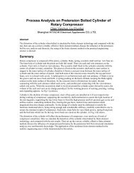
Distribution of mach number in absolute reference<br />
frame at mid-section and near FEGV surfaces<br />
www.ansys.com ANSYS Solutions | Volume 7, Issue 2 2006
CFD Update: What’s New in Computational Fluid Dynamics<br />
26<br />
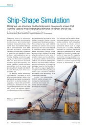
Distribution of first BPF harmonic amplitude along FEGV mid-surface<br />
Area-averaged amplitude of unsteady pressure difference<br />
Relative efficiency of four variants of FEGV<br />
The fan stage efficiency level is almost identical<br />
<strong>for</strong> the first and the fourth FEGV geometries. To explain<br />
the cause of decreasing fan stage efficiency <strong>for</strong> other<br />
geometries, the distribution of total pressure at FEGV<br />
outlet section was determined <strong>for</strong> all variants.<br />
Significant total pressure losses <strong>for</strong> the third geometry<br />
are generated by a vortex flow behavior, which exists<br />
in the hub region <strong>for</strong> this FEGV shape. The fourth<br />
geometry was designed after obtaining calculation<br />
results <strong>for</strong> the third geometry and, there<strong>for</strong>e, high total<br />
pressure losses at the hub region were avoided in<br />
the fourth design. By using ANSYS CFX in this way,<br />
we were able to design an efficient fan that produced<br />
less noise. ■<br />
References:<br />
Yamagata A., Kodama H., Tsuchiya N.: CFD Prediction of<br />
Unsteady Pressures Due to Fan Rotor-Stator Interaction,<br />
ISABE 2003, No. 2003-1130.<br />
Tsuchiya N., Nakamura Y., Goto S., Kodama H., Nozaki O.,<br />
Nishizawa T., Yamamoto K.: Low Noise FEGV Designed by<br />
Numerical Method Based on CFD, ASME, <strong>Turbo</strong>-Expo 2004,<br />
GT-53239.<br />
Total pressure at FEGV outlet<br />
www.ansys.com ANSYS Solutions | Volume 7, Issue 2 2006