high accuracy tester-calibrator PJ 6301
high accuracy tester-calibrator PJ 6301
high accuracy tester-calibrator PJ 6301

You also want an ePaper? Increase the reach of your titles
YUMPU automatically turns print PDFs into web optimized ePapers that Google loves.
<strong>high</strong> <strong>accuracy</strong> <strong>tester</strong>-<strong>calibrator</strong><br />
<strong>PJ</strong> <strong>6301</strong><br />
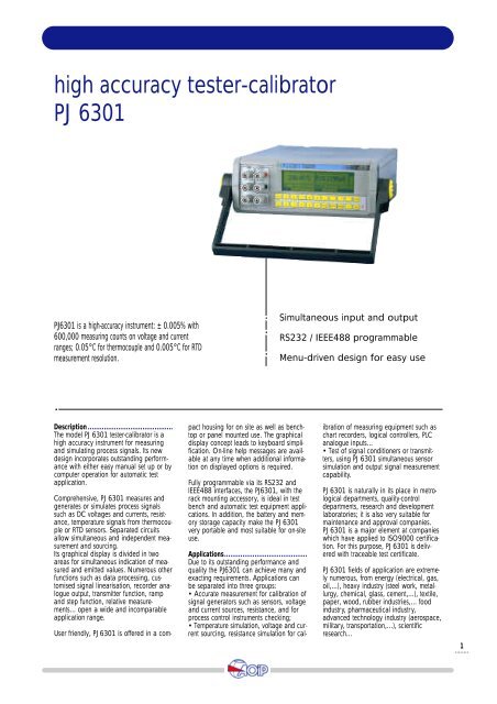
<strong>PJ</strong><strong>6301</strong> is a <strong>high</strong>-<strong>accuracy</strong> instrument: ± 0.005% with<br />
600,000 measuring counts on voltage and current<br />
ranges; 0.05°C for thermocouple and 0.005°C for RTD<br />
measurement resolution.<br />
Simultaneous input and output<br />
RS232 / IEEE488 programmable<br />
Menu-driven design for easy use<br />
Description..........................................<br />
The model <strong>PJ</strong> <strong>6301</strong> <strong>tester</strong>-<strong>calibrator</strong> is a<br />
<strong>high</strong> <strong>accuracy</strong> instrument for measuring<br />
and simulating process signals. Its new<br />
design incorporates outstanding performance<br />
with either easy manual set up or by<br />
computer operation for automatic test<br />
application.<br />
Comprehensive, <strong>PJ</strong> <strong>6301</strong> measures and<br />
generates or simulates process signals<br />
such as DC voltages and currents, resistance,<br />
temperature signals from thermocouple<br />
or RTD sensors. Separated circuits<br />
allow simultaneous and independent measurement<br />
and sourcing.<br />
Its graphical display is divided in two<br />
areas for simultaneous indication of measured<br />
and emitted values. Numerous other<br />
functions such as data processing, customised<br />
signal linearisation, recorder analogue<br />
output, transmitter function, ramp<br />
and step function, relative measurements...<br />
open a wide and incomparable<br />
application range.<br />
User friendly, <strong>PJ</strong> <strong>6301</strong> is offered in a compact<br />
housing for on site as well as benchtop<br />
or panel mounted use. The graphical<br />
display concept leads to keyboard simplification.<br />
On-line help messages are available<br />
at any time when additional information<br />
on displayed options is required.<br />
Fully programmable via its RS232 and<br />
IEEE488 interfaces, the <strong>PJ</strong><strong>6301</strong>, with the<br />
rack mounting accessory, is ideal in test<br />
bench and automatic test equipment applications.<br />
In addition, the battery and memory<br />
storage capacity make the <strong>PJ</strong> <strong>6301</strong><br />
very portable and most suitable for on-site<br />
use.<br />
Applications.........................................<br />
Due to its outstanding performance and<br />
quality the <strong>PJ</strong><strong>6301</strong> can achieve many and<br />
exacting requirements. Applications can<br />
be separated into three groups:<br />
• Accurate measurement for calibration of<br />
signal generators such as sensors, voltage<br />
and current sources, resistance, and for<br />
process control instruments checking;<br />
• Temperature simulation, voltage and current<br />
sourcing, resistance simulation for calibration<br />
of measuring equipment such as<br />
chart recorders, logical controllers, PLC<br />
analogue inputs...<br />
• Test of signal conditioners or transmitters,<br />
using <strong>PJ</strong> <strong>6301</strong> simultaneous sensor<br />
simulation and output signal measurement<br />
capability.<br />
<strong>PJ</strong> <strong>6301</strong> is naturally in its place in metrological<br />
departments, quality-control<br />
departments, research and development<br />
laboratories; it is also very suitable for<br />
maintenance and approval companies.<br />
<strong>PJ</strong> <strong>6301</strong> is a major element at companies<br />
which have applied to ISO9000 certification.<br />
For this purpose, <strong>PJ</strong> <strong>6301</strong> is delivered<br />
with traceable test certificate.<br />
<strong>PJ</strong> <strong>6301</strong> fields of application are extremely<br />
numerous, from energy (electrical, gas,<br />
oil,...), heavy industry (steel work, metallurgy,<br />
chemical, glass, cement,...), textile,<br />
paper, wood, rubber industries,... food<br />
industry, pharmaceutical industry,<br />
advanced technology industry (aerospace,<br />
military, transportation,...), scientific<br />
research...<br />
1
functions<br />
In measurement mode and for all functions. .<br />
Maximum measurement capability: 125%<br />
of the range.<br />
DC voltage<br />
In simulation-sourcing mode and for all<br />
functions .............................................<br />
Settling time < 25 ms to obtain specified<br />
<strong>accuracy</strong>.<br />
Maximum admissible floating voltage<br />
compared with earth: 250 V AC or<br />
350 V peak.<br />
V-<br />
I n p u t<br />
O u t p u t<br />
R e s o l u t i o n R a n g e Accuracy (1) Input impedance R a n g e Accuracy (1)<br />
90 days 1 year 90 days 1 year<br />
0.1 µV<br />
1 µV<br />
10 µV<br />
100 µV<br />
± 60 mV<br />
± 600 mV<br />
± 6 V<br />
± 60 V<br />
0.005% + 4 µV<br />
0.005% + 4 µV<br />
0.005% + 20 µV<br />
0.005% + 200 µV<br />
0.010% + 6 µV<br />
0.010% + 6 µV<br />
0.010% + 30 µV<br />
0.010% + 300 µV<br />
> 1000 MΩ<br />
> 1000 MΩ<br />
> 1000 MΩ<br />
> 10 MΩ<br />
-<br />
- 100 to + 600 mV<br />
- 1 to + 6 V<br />
- 10 to + 60 V<br />
-<br />
0.007% + 4 µV<br />
0.007% + 20 µV<br />
0.007% + 200 µV<br />
-<br />
0.015% + 6 µV<br />
0.015% + 30 µV<br />
0.015% + 500 µV<br />
(1) Accuracy is given in ±(% of reading + nV digits) at 23 ± 1°C, temperature coefficient < 10% of <strong>accuracy</strong> per Celsius degree.<br />
Measurement ......................................<br />
Maximum admissible voltage: 100 V DC<br />
or AC peak.<br />
Common mode maximum admissible voltage:<br />
250 V AC or 350 V peak.<br />
Common mode rejection ratio (60 mV<br />
range) > 150 dB.<br />
DC current<br />
Emission/calibration ............................<br />
Positive output maximum current: 60 mA<br />
(except 60 V range: 30 mA).<br />
Negative output maximum current:<br />
- 5 mA.<br />
Source resistance<br />
< 0.5 mΩ with front panel terminals<br />
< 2 mΩ with rear panel terminals.<br />
Input protected against a temporary misconnection<br />
to - 18 V and + 100 V (DC or<br />
AC peak).<br />
I -<br />
I n p u t<br />
O u t p u t<br />
R e s o l u t i o n R a n g e Accuracy (1) Voltage dro p R a n g e Accuracy (1)<br />
90 days 1 year 90 days 1 year<br />
0.1 µA ± 60 mA 0.010% + 0.4 µA 0.020% + 0.6 µA 1.2 V 0 - 60 mA 0.010% + 0.5 µA 0.020% + 0.8 µA<br />
(1) Accuracy is given in ±(% of reading + nA) at 23 ± 1°C, temperature coefficient < 10% of <strong>accuracy</strong> per Celsius degree.<br />
Measurement ......................................<br />
Electronic protection<br />
When measuring current with a two-wire<br />
transmitter, the current loop can be supplied<br />
from an internal 24 V ± 10%<br />
source.<br />
Resistance<br />
Measurement ......................................<br />
Measurement with two-wire, three-wire or<br />
four-wire resistances.<br />
Open circuit maximum voltage: 10 V.<br />
Emission/calibration ............................<br />
Maximum output voltage: 30 V.<br />
External power supply:<br />
When calibrating a 2 wire transmitter, the<br />
instrument can be powered by an external<br />
power supply ≤ 30 V DC.<br />
Outputs protected against a temporary<br />
misconnection: 100 V DC or AC peak.<br />
Source resistance > 100 MΩ.<br />
Outputs protected against a temporary<br />
misconnection to - 20 V and + 100 V.<br />
0 - 600 Ω<br />
Ω<br />
R a n g e R e s o l u t i o n M e a s u rement curre n t Accuracy (1) Accuracy (1) (2)<br />
1 mΩ<br />
1 mA<br />
4 wire 0.005% + 4 mΩ<br />
3 wire 0.005% + 20 mΩ<br />
I n p u t<br />
90 days 1 year 90 days 1 year<br />
0.010% + 6 mΩ<br />
0.010% + 20 mΩ<br />
0.005% + 8 mΩ<br />
O u t p u t<br />
0.010% + 10 mΩ<br />
0 - 6 000 Ω<br />
10 mΩ<br />
0,1 mA<br />
4 wire 0.005% + 40 mΩ<br />
3 wire 0.005% + 70 mΩ<br />
0.010% + 60 mΩ<br />
0.010% + 80 mΩ<br />
0.005% + 80 mΩ<br />
0.010% + 100 mΩ<br />
(1) In ±(% reading + nΩ) at 23 ± 1°C, temperature coefficient < 10% of <strong>accuracy</strong> per Celsius degree.<br />
(2) Accuracy is given for measurement cur rent between 0.5 mA and 2.5 mA on 600 Ω range and between 0.05 mA and 0.25 mA on 6000 Ω range.<br />
Admissible measurement current from 0.1 mA to 4 mA on 600 Ω range and from 0.01 mA to 0.4 mA on 6000 Ω range (lower <strong>accuracy</strong>)<br />
2
Temperature with thermocouples<br />
Te m p e r a t u re I n p u t Output (2)<br />
T h e rm o c o u p l e<br />
R a n g e R e s o l u t i o n Accuracy (1) (3) R a n g e Accuracy (3)<br />
90 days 1 year 90 days 1 year<br />
K<br />
- 250 to - 200°C<br />
- 200 to - 120°C<br />
- 120 to 0°C<br />
0 to + 1 372°C<br />
0.2°C<br />
0.1°C<br />
0.05°C<br />
0.05°C<br />
1°C<br />
0.3°C<br />
0.2°C<br />
0.010% + 0.1°C<br />
1.5°C<br />
0.5°C<br />
0.3°C<br />
0.015% + 0.2°C<br />
- 240 to - 200°C<br />
- 200 to 0°C<br />
0 to + 1 372°C<br />
1°C<br />
0.3°C<br />
0.01% + 0.1°C<br />
1.5°C<br />
0.5°C<br />
0.015% + 0.2°C<br />
T<br />
- 250 to - 200°C<br />
- 200 to - 0°C<br />
0 to + 400°C<br />
0.2°C<br />
0.05°C<br />
0.05°C<br />
1°C<br />
0.3°C<br />
0.1°C<br />
1.5°C<br />
0.5°C<br />
0.2°C<br />
- 240 to - 200°C<br />
- 200 to 0°C<br />
0 to + 400°C<br />
1°C<br />
0.3°C<br />
0.1°C<br />
1.5°C<br />
0.5°C<br />
0.2°C<br />
J<br />
- 210 to - 100°C<br />
- 100 to + 1 200°C<br />
0.05°C<br />
0.05°C<br />
0.2°C<br />
0.1°C<br />
0.4°C<br />
0.2°C<br />
- 210 to - 100°C<br />
- 100 to + 1 200°C<br />
0.3°C<br />
0.01% + 0.1°C<br />
0.5°C<br />
0.015% + 0.2°C<br />
E<br />
- 250 to - 200°C<br />
- 200 to - 100°C<br />
- 100 to + 1 000°C<br />
0. 1°C<br />
0.05°C<br />
0.05°C<br />
0.5°C<br />
0.2°C<br />
0.1°C<br />
1°C<br />
0.3°C<br />
0.2°C<br />
- 240 to - 200°C<br />
- 200 to - 100°C<br />
- 100 to + 1 000°C<br />
0.5°C<br />
0.2°C<br />
0.1°C<br />
1°C<br />
0.3°C<br />
0.2°C<br />
R<br />
- 50 to + 120°C<br />
+ 120 to + 450°C<br />
+ 450 to + 1 768°C<br />
0.5°C<br />
0.2°C<br />
0.1°C<br />
1°C<br />
0,5°C<br />
0,5°C<br />
2°C<br />
1°C<br />
1°C<br />
- 50 to + 120°C<br />
+ 120 to + 1 768°C<br />
1°C<br />
0.5°C<br />
2°C<br />
1°C<br />
S<br />
- 50 to + 120°C<br />
+ 120 to + 450°C<br />
+ 450 to + 1 768°C<br />
0.5°C<br />
0.2°C<br />
0.1°C<br />
1°C<br />
0.5°C<br />
0.5°C<br />
1.5°C<br />
1°C<br />
1°C<br />
- 50 to + 120°C<br />
+ 120 to + 1 768°C<br />
1°C<br />
0.5°C<br />
2°C<br />
1°C<br />
B<br />
+ 400 to + 900°C<br />
+ 900 to + 1 820°C<br />
0.2°C<br />
0.1°C<br />
1°C<br />
0.5°C<br />
1.5°C<br />
1°C<br />
+ 400 to + 900°C<br />
+ 900 to + 1 820°C<br />
1°C<br />
0.5°C<br />
1.5°C<br />
1°C<br />
U<br />
- 200 to 0°C<br />
0 to + 600°C<br />
0.05°C<br />
0.05°C<br />
0.3°C<br />
0.2°C<br />
0.5°C<br />
0.3°C<br />
- 200 to 0°C<br />
0 to + 600°C<br />
0.3°C<br />
0.2°C<br />
0.4°C<br />
0.2°C<br />
L<br />
- 200 to - 100°C<br />
- 100 to + 900°C<br />
0.05°C<br />
0.05°C<br />
0,2°C<br />
0,1°C<br />
0,3°C<br />
0,2°C<br />
- 200 to - 100°C<br />
- 100 to + 900°C<br />
0.2°C<br />
0.1°C<br />
0.3°C<br />
0.2°C<br />
C<br />
- 20 to + 900°C<br />
+ 900 to + 2 310°C<br />
0.1°C<br />
0.1°C<br />
0.5°C<br />
0.03% + 0.1°C<br />
1°C<br />
0.05% + 0.2°C<br />
- 20 to + 900°C<br />
+ 900 to + 2 310°C<br />
0.4°C<br />
0.03% + 0.1°C<br />
0.5°C<br />
0.05%+ 0.2°C<br />
N<br />
- 240 to - 190°C<br />
- 190 to - 110°C<br />
- 110 to + 1 300°C<br />
0.2°C<br />
0.1°C<br />
0.05°C<br />
1°C<br />
0.5°C<br />
0.2°C<br />
1.5°C<br />
1°C<br />
0.3°C<br />
- 240 to - 100°C<br />
- 100 to + 1 300°C<br />
1°C<br />
0.2°C<br />
1.5°C<br />
0.4°C<br />
P l a t i n e l - 100 to + 1 400°C 0.05°C 0.2°C 0.4°C - 100 to + 1 395°C 0.2°C 0.4°C<br />
M o 0 to + 1 375°C 0.05°C 0.1°C 0.2°C 0 to + 1 375°C 0.2°C 0.3°C<br />
(1) Accuracy given with reference junction at 0°C. With internal reference junction compensation <strong>accuracy</strong> is decreased an additional 0.2°C .<br />
(2) Calibration resolution (all ranges): 0.01°C.<br />
(3) In ±(% reading + n°C) at 23 ± 1°C, temperature coefficient < 10% of <strong>accuracy</strong> per Celsius degree.<br />
3
Temperature with RTD<br />
Te m p e r a t u re I n p u t Output (2)<br />
RT D M e a s u rement range R e s o l u t i o n<br />
Pt 100<br />
Pt 200<br />
Pt 500<br />
Pt 1000<br />
- 220 to 0°C<br />
0 to + 630°C<br />
+ 630 to + 1200°C<br />
- 220 to 0°C<br />
0 to + 630°C<br />
+ 630 to + 798°C<br />
- 220 to 0°C<br />
0 to + 1200°C<br />
- 220 to 0°C<br />
0 to + 630°C<br />
+ 630 to + 1200°C<br />
0.01°C<br />
0.005°C<br />
0.01°C<br />
0.01°C<br />
0.005°C<br />
0.01°C<br />
0.01°C<br />
0.01°C<br />
0.01°C<br />
0.005°C<br />
0.01°C<br />
0.02°C<br />
0.01% + 0.02°C<br />
0.1°C<br />
0.02°C<br />
0.01% + 0.02°C<br />
0.7°C<br />
0.04°C<br />
0.01% + 0.04°C<br />
0.03°C<br />
0.01% + 0.03°C<br />
0.15°C<br />
Accuracy (1) (3)<br />
90 days 1 year<br />
0.04°C<br />
0.015% + 0.04°C<br />
0.2°C<br />
0.04°C<br />
0.015% + 0.04°C<br />
0.15°C<br />
0.06°C<br />
0.015% + 0.06°C<br />
0.05°C<br />
0.015 % + 0.05°C<br />
0.3°C<br />
R a n g e<br />
- 220 to 0°C<br />
0 to + 1200°C<br />
- 220 to 0°C<br />
0 to + 590°C<br />
- 220 to 0°C<br />
0 to + 1200°C<br />
- 220 to 0°C<br />
0 to + 1200°C<br />
Accuracy (3)<br />
90 days 1 year<br />
0.04°C<br />
0.01% + 0.04°C<br />
0.03°C<br />
0.01% + 0.03°C<br />
0.05°C<br />
0.01% + 0.05°C<br />
0.04°C<br />
0.01% + 0.04°C<br />
0.06°C<br />
0.015 % + 0.06°C<br />
0.04°C<br />
0.015% + 0.04°C<br />
0.1°C<br />
0.015% + 0.1°C<br />
0.06°C<br />
0.015% + 0.06°C<br />
Ni 100 - 60 to + 180°C 0.05°C 0.1°C 0.15°C - 60 to + 180°C 0.3°C 0.4°C<br />
(1) Accuracy given with a four-wire sensor.<br />
(2) Resolution (all ranges): 0.01°C<br />
Accuracy is given for external current<br />
- between 0.5 mA and 2.5 mA in Pt 100, Pt 200 and Ni 100 simulation<br />
- of 1 mA in Pt 500 and Pt 1000 simulation<br />
(3) Accuracy is given in ±(% of reading + n °C) at 23 ± 1°C, temperature coefficient < 10% of <strong>accuracy</strong> per Celsius degree.<br />
additional functions<br />
Choice of temperature unit ...................<br />
In measurement or simulation mode temperature<br />
can be displayed in °C, °F or K.<br />
Configuration memory..........................<br />
<strong>PJ</strong><strong>6301</strong> is able to store up to 5 user definable<br />
configuration programs, easily selectable<br />
on request from keyboard.<br />
Input<br />
Alarm thresholds .................................<br />
Two set points, or alarm limit S1 and S2,<br />
can be programmed with audible beep<br />
and relay output.<br />
Peak and valley memory......................<br />
Simultaneous display of current value,<br />
minimum and maximum value measured<br />
since unit initialisation, or since range<br />
switching from initialisation.<br />
Relative measurements («Null» function)<br />
...................................................<br />
Display of difference D (read value)<br />
between M (Measured value) and a value<br />
R. R is either memorised as a reference<br />
during measurement, or edited via keyboard:<br />
D = M - R.<br />
Linearisation by segments L = f(M) ......<br />
Two possibilities are offered:<br />
1- the relation between displayed and<br />
measured values is linear; in that case<br />
slope (a) and offset (b) are programmed<br />
so that displayed value L = aM + b.<br />
2- the relation is not linear, but is known<br />
for a certain number of points. In that<br />
case up to 9 segments (each defined by a<br />
couple of points) can be programmed, to<br />
obtain the closest possible response curve.<br />
Couples are entered as (X 0 , Y 0 ),...(X n ,<br />
Y n ).<br />
Displayed value L = f(M).<br />
Digital filter ........................................<br />
A programmable digital filter enables the<br />
<strong>PJ</strong><strong>6301</strong> to display a smoothed value taking<br />
into account previous measurements.<br />
Trigger function ...................................<br />
Acquisition on request can be replaced by<br />
triggered acquisition, one by one or with<br />
an acquisition procedure where number of<br />
measurements and time interval between<br />
measurements can be programmed.<br />
Measurements of a burst are stored and<br />
can be processed off-line in the various<br />
ways described in the following paragraph.<br />
Measurement memory .........................<br />
Up to 1000 measurements values can be<br />
stored in EEPROM in one burst, or up to<br />
128 burst of one measurement. Bursts are<br />
tagged with an item number, and can be<br />
identified with a label. Data processing<br />
program allows to:<br />
- display contents of a burst<br />
- convert stored data into 4/20 mA or<br />
0/10 V signals to be sent to a device fitted<br />
with analogue input<br />
- download stored data onto a computer<br />
or printer via RS232 interface<br />
Memory can be on request erased partially<br />
or totally.<br />
Programmable recorder analogue output<br />
.....................................................<br />
An analogue output proportioned to any<br />
of the input ranges being measured is<br />
available on the rear terminals.<br />
The output is 0-2.5 Vdc and is suitable for<br />
monitoring displayed values on a chart<br />
recorder.<br />
Printer output .....................................<br />
This digital output is available on RS232<br />
interface to send displayed values onto a<br />
peripheral printer.<br />
Output<br />
Emission values memory ......................<br />
Up to 100 different emission-simulation<br />
values can be stored in memory, even on<br />
different ranges. These values can be<br />
entered by keyboard or via the RS232<br />
link by a computer.<br />
Each value can be sent one by one by<br />
keyboard, or using internal «synthesiser»<br />
function which allows automatic output<br />
according to operator’s requirements.<br />
Step function .......................................<br />
Emitted value can vary by steps, whose<br />
amplitude, direction, and number of iterations<br />
are user programmable.<br />
Ramp function .....................................<br />
This function allows the emitted signal to<br />
vary between various programmable values,<br />
at programmable time intervals.<br />
Ramps can be:<br />
- simple (increasing or decreasing)<br />
- cyclic.<br />
4
Synthesiser function.............................<br />
This function allows to recall manually or<br />
automatically all or a part of memorised<br />
emission values. The generated signal<br />
varies according to memorised data, time<br />
interval between two consecutive values<br />
being programmable.<br />
Scaling................................................<br />
This function allows to display a value A,<br />
and to obtain on terminals an output value<br />
S different from A but linked with relation<br />
S = f(A).<br />
Two possibilities:<br />
- A and S are related by a linear relation,<br />
with programmable slope (a) and offset<br />
(b). In that case the relation between displayed<br />
and emitted values is<br />
S = aA + b.<br />
- The relation between A and S is not linear.<br />
In that case the relation can be<br />
approached by segments. In the same<br />
way as for measurements, 9 sets of values<br />
can be programmed to linearise output<br />
signal from displayed value.<br />
Transmitter function.............................<br />
The <strong>PJ</strong><strong>6301</strong>'s ability to measure and generate<br />
simultaneously is extremely useful in<br />
transmitter loop applications.<br />
The measured signal can be linearised<br />
and converted to a 4-20 mA or 0-10 V<br />
signal available on the output terminals.<br />
The <strong>PJ</strong><strong>6301</strong> then reacts exactly as a programmable<br />
transmitter and interfaces sensor<br />
to process control or monitoring system.<br />
Digital communications.........................<br />
RS 232 and IEEE 488-2 interfaces are<br />
designed for total control of instrument by<br />
external computer.<br />
general specifications<br />
Display ...............................................<br />
Graphical back-lit LCD display, with online<br />
menu and two separated areas for<br />
generation and measurement operation.<br />
600000 counts + clear units + icons +<br />
messages.<br />
Common mode voltage.........................<br />
Max. 250 V between earth and terminals.<br />
Operating conditions............................<br />
Reference temperature: 23 ± 1°C. Reference<br />
relative humidity (RH) 45 to 75%.<br />
Nominal operating temperature and<br />
humidity: 0 to + 50°C, 20 to 75% RH.<br />
Maximum operating temperature and<br />
humidity: - 10 to + 55°C, 10 to 80% RH.<br />
Power supply ......................................<br />
Mains 110 to 240 VAC, 50 to 400 Hz.<br />
Optional battery with internal charger.<br />
Presentation........................................<br />
Bench-top ABS plastic case with rack and<br />
panel mount adapters.<br />
Dimensions: 225 x 88 x 310 mm<br />
Weight: 2 to 3 kg according to hardware<br />
configuration.<br />
Standards ...........................................<br />
For thermocouples type K, T, J, E, R, S, B:<br />
DIN-CEI 584-1 (NFC 42-321)<br />
For thermocouple type L: DIN 43710<br />
For RTD type Pt100: DIN-CEI 751 (NFC<br />
42-330)<br />
For RTD type Ni100: DIN 43760.<br />
Traceability..........................................<br />
AOIP owning in EVRY (France) a metrological<br />
laboratory accredited by French<br />
national bureau of Metrology (COFRAC)<br />
under number 2-1524 in Electricity and<br />
Magnetism and number 2-1525 in<br />
Temperature, <strong>PJ</strong><strong>6301</strong> is traceable to<br />
national and international standards. It is<br />
delivered with checking report available<br />
for ISO 9000. On request, it can be delivered<br />
with full calibration certificate.<br />
sensors<br />
Various sensors are available from our catalogue<br />
and can be delivered as options<br />
including traceable temperature probes<br />
and process sensors.<br />
ordering instructions<br />
Tester-<strong>calibrator</strong> <strong>PJ</strong> <strong>6301</strong>-3<br />
Tester-<strong>calibrator</strong> + battery <strong>PJ</strong> <strong>6301</strong>-4<br />
Accessories ........................................<br />
Soft carrying case AN 6901<br />
RS 232 lead 9/25 female AN 5874<br />
RS 232 lead 9/9 male AN 5875<br />
RS 232 lead 9/25 male AN 5876<br />
IEEE 488 lead AN 5836<br />
Panel mounting kit AN 5883<br />
Rack mounting kit AN 5884<br />
Calibration certificate On request<br />
Processing software On request<br />
Sensors<br />
On request<br />
B.P. 182 - F 91006 EVRY Cedex<br />
Tel. 33 1 69 36 50 60<br />
Fax 33 1 60 77 82 97<br />
Email: export@aoip.com<br />
Specifications subject to modification without prior notice<br />
5