PDF File - Hardware Verification Group - Concordia University
PDF File - Hardware Verification Group - Concordia University
PDF File - Hardware Verification Group - Concordia University

You also want an ePaper? Increase the reach of your titles
YUMPU automatically turns print PDFs into web optimized ePapers that Google loves.
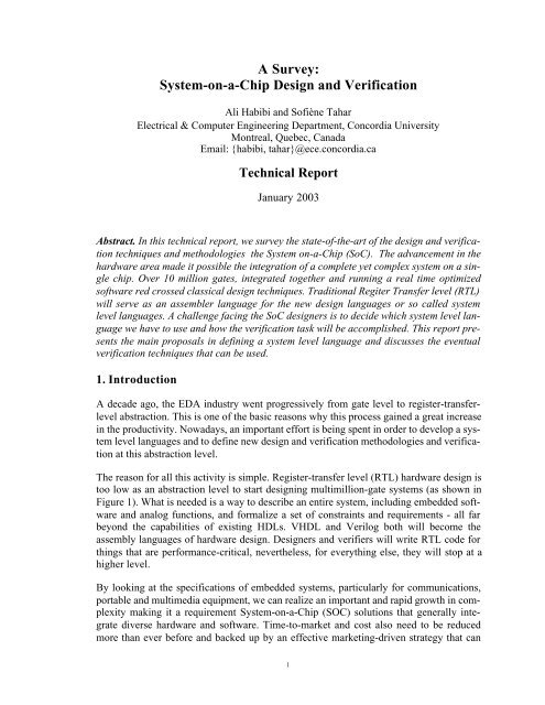
A Survey:<br />
System-on-a-Chip Design and <strong>Verification</strong><br />
Ali Habibi and Sofiène Tahar<br />
Electrical & Computer Engineering Department, <strong>Concordia</strong> <strong>University</strong><br />
Montreal, Quebec, Canada<br />
Email: {habibi, tahar}@ece.concordia.ca<br />
Technical Report<br />
January 2003<br />
Abstract. In this technical report, we survey the state-of-the-art of the design and verification<br />
techniques and methodologies the System on-a-Chip (SoC). The advancement in the<br />
hardware area made it possible the integration of a complete yet complex system on a single<br />
chip. Over 10 million gates, integrated together and running a real time optimized<br />
software red crossed classical design techniques. Traditional Regiter Transfer level (RTL)<br />
will serve as an assembler language for the new design languages or so called system<br />
level languages. A challenge facing the SoC designers is to decide which system level language<br />
we have to use and how the verification task will be accomplished. This report presents<br />
the main proposals in defining a system level language and discusses the eventual<br />
verification techniques that can be used.<br />
1. Introduction<br />
A decade ago, the EDA industry went progressively from gate level to register-transferlevel<br />
abstraction. This is one of the basic reasons why this process gained a great increase<br />
in the productivity. Nowadays, an important effort is being spent in order to develop a system<br />
level languages and to define new design and verification methodologies and verification<br />
at this abstraction level.<br />
The reason for all this activity is simple. Register-transfer level (RTL) hardware design is<br />
too low as an abstraction level to start designing multimillion-gate systems (as shown in<br />
Figure 1). What is needed is a way to describe an entire system, including embedded software<br />
and analog functions, and formalize a set of constraints and requirements - all far<br />
beyond the capabilities of existing HDLs. VHDL and Verilog both will become the<br />
assembly languages of hardware design. Designers and verifiers will write RTL code for<br />
things that are performance-critical, nevertheless, for everything else, they will stop at a<br />
higher level.<br />
By looking at the specifications of embedded systems, particularly for communications,<br />
portable and multimedia equipment, we can realize an important and rapid growth in complexity<br />
making it a requirement System-on-a-Chip (SOC) solutions that generally integrate<br />
diverse hardware and software. Time-to-market and cost also need to be reduced<br />
more than ever before and backed up by an effective marketing-driven strategy that can<br />
1
meet today's highly competitive and demanding circumstances. To achieve all this, the<br />
product development process must assure the product specification phase is integrated<br />
smoothly with the product design phase, allowing the customer's demands, marketing<br />
goals and designer expertise, to be evaluated and analyzed at significantly less cost in time<br />
and resources, and to be rapidly incorporated into the final product.<br />
(a) The complexity growth.<br />
Figure 1. <strong>Hardware</strong> Design Evolution [43].<br />
(b) The scaling of the dimensions.<br />
System level languages proposals can be classified into three main classes. First, reusing<br />
classical hardware languages such as extending Verilog to SystemVerilog [30]. Second,<br />
readapting software languages and methodologies (C/C++ [44], Java [5], UML [16], etc.).<br />
Third, creating new languages specified for system level design (Rosetta [2] for example).<br />
The verification of SoC is a more serious bottelneck in the design cycle. In fact, defining<br />
SoC design language and methodology is a matter of time, however, the verification is a<br />
very open and ambigous question. Functional verification is consuming an inordinate<br />
amount of the design cycle time. Estimates vary, but most analysts and engineers agree<br />
that as much as 70 percent of the design cycle is consumed by functional verification. In<br />
addition, the quality of these verification efforts has become more important than ever<br />
because the latest silicon processes are now accompanied by higher re-spin costs. No<br />
doubt, classical random simulation is no more able to handle actual designs. Going further<br />
in complexity and considering hardware/software systems will be out of the range of the<br />
nowadays used simulation based techniques [32].<br />
For intance, the main trends in defining new verification methodologies are considering a<br />
hybrid combination of formal, semi-formal and simulation techniques. The first step in<br />
2
this direction was the definition of a standard for assertion languages. Such languages,<br />
which let engineers check properties during simulation and formal verification, have<br />
become crucial for complex chip design. For instance, the Sugar language [4] from IBM<br />
was selected as a standard for this effect. A lot is expected from combining an assertion<br />
language such as Sugar with both smart test generation and coverage analysis. This kind<br />
of hybrid techniques can offer a partial answer to the question: “Is verification task complete?”<br />
This report is divided into three main sections. In Section 2, we introduce the concept of a<br />
System Level Language. We presented the UML language as a case study to illustrate the<br />
definition of such a class of languages in the software engineering domain. In Section 3,<br />
we consider the main proposals regarding the definition of a hardware system level language.<br />
In Section 4, we classify the main promising verification techniques for SoC verification.<br />
Finally, Section 5 concludes the report.<br />
2. System-Level Design<br />
2.1. Problem Statement<br />
Modern electronic systems grow in complexity encouraging combinations of different<br />
types of components: microprocessors, DSPs, memories, etc. On the other side, and in the<br />
same time, designers and programmers are asked to meet demands for shorter development<br />
time and lower development cost. Designers agreed that there is no way to meet this<br />
difficult target expect using higher abstraction levels in the design process, so-called System<br />
Level Design [45]. System level design, requires system level tools that simultaneously<br />
handle both hardware and software, for modeling, partitioning, verification and<br />
synthesis of the complete system.<br />
The software evolution story is replayed again in the hardware world. Migrating to the<br />
system level of abstraction introduces a higher order of complexity. To reach the next<br />
level of complexity, EDA vendors and analysts are telling designers that another leap is<br />
necessary - from RTL to system-level design. Such a leap implies that an increasing<br />
amount of hardware design will be done using C/C++, Java, SuperLog, or other high-level<br />
languages, while RTL VHDL and Verilog will be relegated to smaller blocks of timingcritical<br />
logic.<br />
Nevertheless, a fact is the level of highest abstraction will be the one that survives, and<br />
that is clearly the software domain. Considering the economic reality, this transition will<br />
not be abrupt, but it will occur more as an evolution than a revolution. The most likely<br />
transition will be along the lines that software followed as it evolved from a strict use of<br />
hand-coded assembler in the fifties to extensive use of compilers in the sixties.<br />
The most realistic scenario will start by migrating the non-critical portions of time-to-market-driven<br />
designs to higher levels. Then, progressively over time, more sophisticated<br />
compiler and synthesis technology augmented by increasing hardware functionality will<br />
extend the reach of automatic techniques until only extremely critical portions of highly<br />
performance-driven designs will be implemented at the register transfer level.<br />
3
Eventually, the software and hardware design will end by getting into a single flow. Optimistically,<br />
in a few years, the difference, if it will exist, will be a matter of compiler<br />
options ("-software" or "-hardware"). However, to get there, we need at first to define a<br />
system level language.<br />
2.2. Proposed Solutions<br />
The usage of a system level language is a direct result of the way the SoC design process<br />
works [31]. Following the software evolution, the most likely methodology would be to<br />
push toward successive refinement, an extremely successful methodology in software<br />
development. A possible solution is to define what are the basic requirements for a system<br />
level language; intuitively, we would first spend a look to the way software design is actually<br />
performed.<br />
No doubts, a short-term solution will come from languages that "push up" from or extend<br />
current HDL-based methodologies. We can not omit that languages like SuperLog [46]<br />
hold great promise for the next three to four years basically because SuperLog does not<br />
require a radical shift in methodologies and allows groups to retain legacy code. This<br />
approach can be seen as a refinement of the existent languages. Some people define<br />
SuperLog as “Verilog done right”.<br />
The medium-range solutions will likely be C++-based languages that have hardware<br />
design capabilities, we mention here SystemC [49] and Cynlib [10] as two promising languages.<br />
The revolution can also come from the Java side.<br />
Long-term language solutions will likely come from new languages developed just specifically<br />
to work at the system level such as Rosetta [2] which promise to make true systemlevel<br />
design a reality.<br />
2.3. Case Study: UML as a Software System Level Languages<br />
Software developers faced the problem of large yet complex projects long time before<br />
their hardware counterparts. Dedicated system level languages have been introduced since<br />
the last 80s. However, the most and widely used solution is the Unified Modeling Language<br />
(UML) [8]. No one can deny that fact is that UML is becoming a lingua franca for<br />
system level modeling. Nevertheless, an open question is whether UML is rich enough to<br />
represent hardware adequately.<br />
As defined, UML is a vendor and tool-dependent notation for specifying, visualizing, constructing<br />
and documenting software systems. Originally UML was developed by Rational<br />
Software Corp. and its partners and now under the auspices of the Object Management<br />
<strong>Group</strong> (OMG) [8]. The first yet principle objective of UML was to let software developers<br />
draw diagrams that can be, at least in theory, universally understood. At the time when<br />
UML was born, it was quite early to think about the support of hardware systems. However,<br />
the SoC facto made no choice for UML designers to rethink about their language if<br />
they want to keep it as a "default" system level language.<br />
4
Most hardware companies are keeping an eye on UML. Trying, to cut the road on the software<br />
developers, Cadence as one of the leading EDA companies, for example, is looking<br />
at UML as a possible source of input into the Cadence VCC hardware-software co-design<br />
system. Moreover, Cadence has joined the OMG as an auditing member and is tracking<br />
OMG's real-time analysis and design working group. On the other side, the embedded<br />
software companies are also tracking the UML guest. For instance, Project Technology<br />
has developed a prototype UML-to-VHDL compiler [16].<br />
In an optimistic way, people supporting UML consider that this system level language is<br />
rich enough to represent any system. They go further and say that designing a SoC in<br />
UML will be as simple as taking requirements for the entire system and breaking it down<br />
into big subsystems, then, the last step will be a simple breaking into hardware, software<br />
and mechanical components.<br />
The People in the EDA busniss look at the problem in a more realistic way. They consider<br />
that UML needs much more work before it can fully support real-time embedded hardware<br />
[21]. A fact is UML can not represent an "architectural" view with such attributes as<br />
hierarchy, structure, connectivity or bus width. No doubt this limitation will make it hard<br />
to do any real estimation about the use of UML.<br />
Omitting the technical constraints, a fundamental problem facing UML is the question of<br />
receptivity. Will hardware engineers move up from block diagrams and schematics to the<br />
higher-level abstraction of UML? The first step was done by software people to upgrade<br />
UML to support hardware by adding a causal model offering an automatic conversion of<br />
requirements into test vectors. However, without a strong collaboration between both<br />
hardware and software plyers there is no way for UML to become a default system level<br />
language for SoC.<br />
3. System-on-a-Chip System Level Language<br />
3.1. Requirements<br />
Any language proposing to support system-on-a-chip design must address two important<br />
design characteristics. Namely, the integration of information from multiple heterogeneous<br />
sources and the ability to work at high levels of abstraction with incomplete information<br />
[31]. This can be defined as:<br />
- Support for integrating domain specific specifications<br />
- Composition of models of computation that describe systems and components<br />
- Representation and integration of constraint information<br />
- Support for more abstract modeling<br />
- Moving up from implementation technology<br />
- Support for predictive analysis and verification<br />
- Within specific domains<br />
- Across multiple domains<br />
5
- Formal semantics is a must<br />
- Consistent and continuous design process and exploration of design space from specification<br />
design to implementation design<br />
- Design reuse, which means not only of component IP but also specification IP and<br />
design case IP.<br />
3.2. Extending Existent HDLs: SystemVerilog<br />
A radically revised Verilog [47] language took shape at the International HDL Conference<br />
as presenters unveiled a language reaching toward much higher levels of abstraction. SystemVerilog<br />
blends Verilog, C/C++ and Co-Design Automation's SuperLog language to<br />
bring unprecedented capabilities to RTL chip designers.<br />
As shown in Figure 2, key additions to SystemVerilog, which is a set of extensions to the<br />
IEEE 1364-2001 Verilog <strong>Hardware</strong> Description Language [30] to aid in the creation and<br />
verification of abstract architectural level models, include interfaces that allow module<br />
connections at a high level of abstraction; C-language constructs such as globals; and an<br />
assertion construct that allows property checking. SystemVerilog includes the synthesizable<br />
subset of SuperLog, and its assertion capability will likely be derived from the Design<br />
Assertion Subset that Co-Design and Real Intent Corp. recently donated to the Accellera<br />
standards body.<br />
Figure 2. SystemVerilog [27].<br />
With all these enhancements, SystemVerilog may remove some of the impetus from C-<br />
language design, at least for register-transfer-level chip designers. The basic intent is to<br />
6
give Verilog a new level of modeling abstraction, and to extend its capability to verify<br />
large designs.<br />
Interfaces are one of the most significant introductions in SystemVerilog. The IEEE 1364-<br />
2001 Verilog spec, Verilog-2001, connects one module to another through module ports,<br />
but this is tedious. The new "interface" construct makes it possible to begin a design without<br />
first establishing all the module interconnections. Usually, interfaces allow the grouping<br />
of connections between modules, and can also contain logic. In other terms, it is<br />
possible to have procedures and other functionality within the interface itself. Also important<br />
is the introduction of global declarations and statements. For now, only module and<br />
primitive names can be global in Verilog. SystemVerilog will allow global variables and<br />
functions via a new "$root" construct.<br />
Abstract data types are another addition. SystemVerilog borrows the C-language "char"<br />
and "int" data types, allowing C/C++ code to be directly used in Verilog models and verification<br />
routines. Both are two-state signed variables. Other new constructs include "bit,"<br />
a two-state unsigned data type, and "logic," a four-state unsigned data type that claims<br />
more versatility than the existing "reg" and "net" data types. Other new features include<br />
signed and unsigned modifiers, user-defined types, enumerated types, structures and<br />
unions, a "jump" statement and parameterizable data types within modules. SystemVerilog<br />
also removes any restrictions on module ports, allowing users to pass arrays and<br />
structures through ports.<br />
The slogan of the people supporting Verilog is: "The right solution is to extend what<br />
works". However, this may face a harsh critisim from people supporting C++ based solutions<br />
and who advance that Verilog or SystemVerilog or whatever is the Verilog based<br />
name will not offer a short simulation time. The debate is quite hard and the last word will<br />
not be said soon!<br />
3.3. Extending Software Languages<br />
Some optimistic software designers are supporting the establishment of C/C++ [25] or<br />
even Java [29] based languages for future SoC designs. They think that, over time,<br />
improvements in automatic methods and increases in hardware functionality will extend<br />
the pieces handled automatically to where whole designs can be implemented by "cc -silicon".<br />
In the near term, however, tools are not going to be good enough and manual refinement<br />
will be required. This means that the version of the language that will be used must<br />
allow for the expression of hardware at lower levels, not just the algorithmic level.<br />
Mainly reusing existent languages is performed either by extending the language itself (by<br />
adding new keywords and constructors) or by defining new libraries allowing the description<br />
of hardware systems. The most relevant approaches consider either C/C++ or Java. In<br />
following, we will put more light on the proposals based on these two languages.<br />
7
3.3.1. C/C++ Based Proposals<br />
Over the past decade, several different projects have undertaken the task of extending C to<br />
support hardware [25], including SpecC [13] at the <strong>University</strong> of California, Irvin, <strong>Hardware</strong>C<br />
[12], Handel-C [25] at Oxford <strong>University</strong> (now moved to Embedded Solutions<br />
Ltd.), SystemC++ [37] at C Level Design Inc., SystemC [48] at Synopsys Inc., and Cynlib<br />
[10] at CynApps.<br />
These variety of projects fall roughly into two complementary categories. One category,<br />
exemplified by SpecC, has focused on adding keywords to the basic C language, supporting<br />
hardware description at a high level as a basis for synthesis [13]. The other category,<br />
exemplified by SystemC, exploits the extensibility of C++ to provide a basic set of hardware<br />
primitives that can be easily extended into higher level support [44]. These two complementary<br />
approaches span all levels of hardware description (algorithmic, modular,<br />
cycle-accurate, and RTL levels).<br />
People supporting this approach argue that the best way to do system-level design is with<br />
a general-purpose language and that C++ is clearly the best choice. Because it is extendible<br />
and notions such as concurrency can be easily represented in class libraries. Besides,<br />
the object-oriented nature of C++ corresponds perfectly to the HDL hierarchy [51].<br />
The art of applying SoCs to real systems is dominated by software. So it is easy to see why<br />
C/C++-based design languages are rapidly gaining popularity. Many have mistakenly<br />
believed that such languages, like SystemC, aim to replace hardware-description languages,<br />
such as Verilog, for pure hardware design at the register transfer level. But that<br />
holds very little advantage, and the vast majority of companies backing SystemC, including<br />
CoWare, are not trying to replace the Verilog designer.<br />
3.3.1.1. SpecC<br />
The SpecC language is defined as extension of the ANSI-C programming language [15].<br />
This language is a formal notation intended for the specification and design of digital<br />
embedded systems including hardware and software. Built on top of the ANSI-C programming<br />
language, the SpecC language supports concepts essential for embedded systems<br />
design, including behavioral and structural hierarchy, concurrency, communication, synchronization,<br />
state transitions, exception handling and timing [14].<br />
Originally, the SpecC language was developed at <strong>University</strong> of California, Irvine, with<br />
sponsorship from Toshiba, Hitachi and other companies [13]. Based on C, it allows the<br />
same semantics and syntax to be used to represent specifications in a conceptual system,<br />
hardware, software, and, most importantly, intermediate specification and information<br />
during hardware/software co-design stages.<br />
SpecC targets the specification and design of SoCs or embedded systems including software<br />
and hardware whether using fixed platforms, integrating systems from different IPs,<br />
or synthesizing system blocks from programming or hardware description languages [24].<br />
The SpecC methodology leads designers from an executable specification to an RTL<br />
implementation through a well-defined sequence of steps. Each model is described and<br />
8
guidelines are given for generating these models from executable specifications. SpecC is<br />
intended to be used for specification analysis, specification capturing and system codesign<br />
as described in Figure 3.<br />
To defend SpecC against C++ proposals and mainly SystemC, when this latter was first<br />
introduced in 1999, SpecC supporters claim that SystemC is primarily aimed at simulation,<br />
however, SpecC was developed with synthesis and verification in mind. They also<br />
considered that SystemC targets RTL design, but SpecC is a system-level design language<br />
intended for specification and architectural modeling. Nevertheless, after the release of the<br />
version 2.0 of SystemC, all these argument were broken. In fact, SystemC is nowadays<br />
supporting all System Level Design requirements.<br />
Figure 3. SpecC in the Design Flow[14].<br />
3.3.1.2. <strong>Hardware</strong>C<br />
Under the same class of C-based languages we find also a language called <strong>Hardware</strong>C<br />
[34]. This is a language that uniformly incorporates both functionality and design constraints.<br />
A <strong>Hardware</strong>C description is synthesized and optimized by the Hercules and Hebe<br />
system [11], where tradeoffs are made in producing an implementation satisfying the timing<br />
and resource constraints that the user has imposed on the design. The resulting implementation<br />
is in terms of an interconnection of logic and registers described in a format<br />
called the Structural Logic Intermediate Format [33].<br />
<strong>Hardware</strong>C attempts to satisfy the requirements stated above. As its name suggests, it is<br />
based on the syntax of the C programming language. The language has its own hardware<br />
semantics, and differs from the C programming language in many respects. In particular,<br />
numerous enhancements are made to increase the expressive power of the language, as<br />
well as to facilitate hardware description [34]. The major features of <strong>Hardware</strong>C are the<br />
following:<br />
9
•Both procedural and declarative semantics - Designs can be described in <strong>Hardware</strong>C<br />
either as a sequence of operations and/or as a structural interconnection of components.<br />
•Processes and interprocess communication - <strong>Hardware</strong>C models hardware as a set of<br />
concurrent processes that interact with each other through either port passing or message<br />
passing mechanisms. This permits the modeling of concurrency at the functional<br />
level.<br />
•Unbound and bound calls - An unbound call invokes the functionality corresponding<br />
to a called model. In addition, <strong>Hardware</strong>C supports bound call that allows the<br />
designer to constrain the implementation by explicitly specifying the particular<br />
instance of the called model used to implement the call, i.e. bind the call to an<br />
instance.<br />
•Template models - <strong>Hardware</strong>C allows a single description to be used for a group of<br />
similar behaviors through the use of template models. A template model is a model<br />
that takes in addition to its formal parameters one or more integer parameters, e.g. an<br />
adder template that describes all adders of any given size.<br />
•Varying degrees of parallelism - For imperative semantic models, <strong>Hardware</strong>C offers<br />
the designer the ability to adjust the degree of parallelism in a given design through<br />
the use of sequential ([ ]), data-parallel (f g), and parallel (< >) groupings of operations.<br />
•Constraint specification - Timing constraints are supported through tagging of statements,<br />
where lower and upper bounds are imposed on the time separation between<br />
the tags. Resource constraints limit the number and binding of operations to<br />
resources in the final implementation.<br />
As any real system a SoC is no more than a number of entities and objects interacting<br />
together. This is the reason for the limitation of the C-based proposals. By reference to<br />
software design, languages that can be used at the system level have to be preferably<br />
object-oriented. This is the reason why nowadays more mature proposals are based on<br />
C++. In this report we will discuss mainly two C++ based proposals: Cynlib and SystemC.<br />
3.3.1.3. Cynlib<br />
Cynlib provides the vocabulary for hardware modeling in C++. It is a set of C++ classes<br />
which implement many of the features found in the Verilog and VHDL hardware description<br />
languages. It is considered as a "Verilog-dialect" of C++, but it is more correct to say<br />
that it is a class library that implements many of the Verilog semantic features. The purpose<br />
of this library is to create a C++ environment in which both hardware and testing<br />
environment can be modeled and simulated [10].<br />
Cynlib supports the development of hardware in a C/C++ environment. To do this, Cynlib<br />
extends the capabilities of C/C++ by supplying the following features, Concurrent Execution<br />
Model, Cycle-Based, Modules, Ports, Threads, Deferred Assignments, Two-state data<br />
values, Multiple clocks and Debugging support.<br />
10
By using Cynlib to model at the highest levels of abstraction and throughout the design<br />
process, any problems (bugs) with the algorithm or implementation will get fixed as early<br />
as possible. For example, it is much easier to isolate, debug and fix a protocol error at the<br />
algorithmic level than it is at the register-transfer level. In the worst case, fixing the RTL<br />
could be as time-consuming as adding or removing states from the finite state machine<br />
and reworking the data path. Of course, this is assuming that the bug can be easily identified<br />
as a protocol error in the first place.<br />
Another advantage of design with Cynlib and Cynthesizer [22] is that designers can use<br />
the object-oriented features of C++ to produce a more natural and understandable representation<br />
of the design. The most obvious application is the use of C++ classes as highlevel<br />
data structures. Using high-level data structures where appropriate provides a less<br />
error-prone approach to design. Cynthesizer's ability to transform object-oriented features<br />
of C++ (such as classes) to Verilog or VHDL allows designers to maintain the usage of<br />
these features throughout the design process.<br />
Finally, adopting C++ as a design language promotes a unified flow between hardware<br />
and software designers. Most system and algorithm developers have been working in C++<br />
for years. By using Cynlib C++ to describe hardware, we get into a situation where the<br />
algorithm, the software, the hardware and the testbench are all written in the same established<br />
language. The complete Forte chain is illustrated in Figure 4.<br />
.<br />
Figure 4. Cynapp Proposal [22].<br />
11
3.3.1.4. SystemC<br />
SystemC [49] is also among a group of design languages and extensions being proposed to<br />
raise the abstraction level for hardware verification. It is expacted to make a stronger<br />
effect in the area of architecture, the co-design and integration of hardware and software<br />
[41]. The reason lies partly in the deliberate choice to extend a software language with<br />
nonproprietary extensions to describe hardware and system-level modeling. However,<br />
SystemC is merely a language, so a greater part of the reason for any success in this area is<br />
the availability of supporting tools and methodologies proved to cut design cycles at such<br />
leading companies as Fujitsu, Matsushita, Sony and STMicroelectronics.<br />
SystemC comes to fill a gap between traditional HDLs and software-development methods<br />
based on C/C++. Developed and managed by leading EDA and electronics companies,<br />
SystemC comprises C++ class libraries and a simulation kernel used for creating<br />
behavioral- and register-transfer-level designs. Combined with commercial synthesis<br />
tools, SystemC can provide the common development environment needed to support<br />
software engineers working in C/C++ and hardware engineers working in HDLs such as<br />
Verilog or VHDL.<br />
Designers have started to create virtual platforms of their SoC designs in C or SystemC for<br />
good reasons. First, they can provide an early simulation platform for the system integration<br />
that executes much faster than HDL-based co-verification. Second, they can verify<br />
the architecture at an early stage of the design process, testing different hardware-software<br />
partitions and evaluating the effects of architectural decisions before implementation.<br />
After all, by the time they are coding in RTL, the hardware architecture is established and<br />
there is little room for flexibility. Third, they can start work on derivative or next-generation<br />
designs by reusing the platform before the first-generation design is complete [48].<br />
Simulating in C or SystemC avoids the need to use the Verilog Program Language Interface<br />
(PLI) [47] or VHDL Foreign Language Interface (FLI), both of which are used to<br />
hook C-based models or testbenches to HDL simulations. By converting to C, a single<br />
executable code can be used hence there is no need for a PLI or FLI, which becomes real<br />
bottlenecks in large simulations.<br />
Virtual platforms can, and should, be used at various abstraction levels, starting with a<br />
very simple functional description and then refining towards implementation. As each part<br />
(that includes hardware or software) of the design is refined, it can be tested in the context<br />
of the entire system. Often, parts of the design that did not interface with the new block<br />
being tested can be run at higher levels of abstraction to speed simulations.<br />
The main question: will SystemC primarily be used by the small number of system<br />
designers already working in C/C++ or by the much larger number of RTL chip designers<br />
using VHDL or Verilog? The latter group has so far shown a lot of skepticism about C-<br />
language design and has warmed more to SystemVerilog and then SuperLog as a way of<br />
moving up in abstraction.<br />
The next question: why wouldl system designers benefit from system? There are already<br />
SystemC tools that help automate the transition from C to HDLs. The best argument,<br />
12
probably, is that SystemC models of intellectual-property (IP) blocks can be exchanged<br />
with other companies, while proprietary C models generally cannot.<br />
The point that may often be missed is that C/C++ language design is already in widespread<br />
use today. It is being used by many major electronics manufacturers, particularly in<br />
Europe, for system-level modeling and silicon intellectual property (IP) design. In this<br />
sense, C language design is an old methodology, not a new one.<br />
Most of these companies, however, use their own proprietary C/C++ class libraries, making<br />
IP exchange very difficult. That's where SystemC comes in. One standardized library<br />
will allow companies to mix and match C language IP from different sources. SystemC is<br />
really about IP modeling, not forcing RTL designers into a new methodology.<br />
C language models can also help speed RTL simulation. It has always been possible to<br />
bring in C language models through the Verilog programming language interface (PLI),<br />
but some vendors are looking at more efficient ways to create this link. C/C++ language<br />
approaches to testbench generation, such as Cadence Design Systems' TestBuilder library,<br />
may also appeal to some designers.<br />
New releases of Cadence Design Systems Inc.'s Signal Processing Worksystem (SPW)<br />
software and Axys Design Automation Inc.'s MaxSim Developer Suite increase support<br />
for SystemC. Designers are now allowed to add custom blocks using SystemC using<br />
SPW. The tight connection SPW 4.8 has with SystemC 2.0 - through a Block Wizard -<br />
accelerates reuse of models written in an industry-standard modeling language, as well as<br />
models customers have written in SPW. Cadence will also announce that it is donating its<br />
Testbuilder class libraries to the Open SystemC Initiative to encourage testbench reuse.<br />
Mentor Graphics Corp. has also added a C language interface to its Seamless hardware/<br />
software co-verification environment that lets designers use mixed C/C++ and HDL<br />
descriptions for hardware. The interface, called C-Bridge, will be included with Seamless<br />
version 4.3, which is to be released in late March 2003. HDL simulation users today can<br />
bring in C code through the Verilog programming language interface (PLI) or VHDL foreign<br />
language interface (FLI), but C-Bridge supports faster performance and a higher level<br />
of abstraction. The interface supports abstract reads and writes for bus connections, but<br />
can still be cycle-accurate. C-Bridge provides an applications programming interface<br />
(API). To use it, designers adapt their C language models to read and write through the<br />
API. They instantiate the models in Seamless, where they're dynamically loaded into<br />
instruction-set simulation (ISS). However, C-Bridge provides its own source-level debugging<br />
environment rather than using the ISS debugger. C-Bridge imposes no limitations on<br />
C language code, and can be used with SystemC version 2.0 models.<br />
SystemC in one of the most important players as a future SoC design and verification language.<br />
The big interest given by the major companies in the SoC design and verification<br />
fields to SystemC is quite a good proof for that. The debate is being concentrated on either<br />
going for SystemVerilog (and then SuperLog) or for SystemC. For instance, both<br />
approaches are coexisting together; they eventually could play together in the future.<br />
13
3.3.2. Java-Based Proposals<br />
While there has been some discussion about the potential of Java as a system-level language<br />
or high-level hardware description language (HDL), LavaLogic [5] may be the first<br />
commercial EDA provider to bring that option into contemporary design systems. The<br />
company's Java-to-RTL compiler is an "architectural synthesis" tool that turns Java into<br />
synthesizable HDL code. LavaLogic is offering a tool that will take high-level Java<br />
descriptions down to gate-level net-lists, starting with FPGAs [29]. The architecture of the<br />
Lavalogic solution is given in Figure 5.<br />
According to Java advocates, Java appears to be the purest language to solve the productivity<br />
problems currently at hand. They also claim that the language can express high-level<br />
concepts with far less code than today's HDLs, yet offer more support for concurrency<br />
than C or C++.<br />
Specifically, LavaLogic advances that the code required for a functional description in<br />
Java is typically one-tenth that required for Verilog. Java simulation models are 100 to<br />
1,000 times faster. This is what the company advised however no rigorous proof was done<br />
until now regarding this point.<br />
Figure 5. Lavalogic Java Based Proposal [5].<br />
14
The main point all Java advocates stressed in comparing their approach to those C/C++ is<br />
the concurrency. In fact, a classical problem with C and C++ is their inherent inability to<br />
express concurrency. In Java, in contrast, concurrency can be explicitly invoked with<br />
threads. Nevertheless, this unique criteria for comparison is not enough to balance the<br />
choice C/C++ to Java. Java can be classified as the "next best" choice after C++, since it<br />
does not support templates or operator overloading, resulting in a need for numerous procedure<br />
calls.<br />
3.4. Developing a new Language<br />
3.4.1. SuperLog and SystemVerilog<br />
SuperLog [46] is a Verilog superset that includes constructs from the C programming language<br />
Because of its Verilog compatibility, it has earned good reviews from chip designers<br />
in such forums as the E-Mail Synopsys User's <strong>Group</strong>, where some designers have<br />
expressed considerable skepticism about C language hardware design. SuperLog holds a<br />
great promise for the next three to four years. It is the case mainly because SuperLog does<br />
not require a radical shift in methodologies and allows groups to retain legacy code.<br />
SuperLog combines the simplicity of Verilog and the power of C, and augments the mix<br />
with a wealth of verification and system features [20]. Realizing that there is no point in<br />
having a language without being able to do something with it, ex Co-Design (bought<br />
recently by Synopsys) also offers a suite of simulation tools making it ready for industrial<br />
applications.<br />
Figure 6. From Verilog to SupeLog [36].<br />
For now we have Verilog 2001 at the lower end of the sophistication spectrum ("jolly nice<br />
but lacking a lot of features") and SuperLog at the other end ("incredibly powerful, but as<br />
yet falling well short of industry-wide support"). This is where Accellera reenters the picture.<br />
By working with Co-design and others to come up with a common meeting ground,<br />
which is SystemVerilog 3.0, Figure 6.<br />
15
Figure 7. SuperLog Description [36].<br />
The great advantage for SystemVerilog 3.0 from most people's perspective is that it<br />
includes things like assertions and extended synthesis capabilities, and it is an Accellera<br />
standard, so it will quickly gain widespread adoption. The advantage for Co-Design is that<br />
it's a step along the way to transmogrifying the Verilog everyone is using into SuperLog.<br />
Actually Figure 6 is somehow simplifief, because there could be a number of intermediate<br />
steps before SystemVerilog 3.0 evolves into SuperLog. Figure 7 displays how Co-Design<br />
expects SuperLog to be.<br />
SuperLog, as described in Figure 7, retains most of the features of Verilog and VHDL,<br />
including support for hierarchy, events, timing, concurrency and multivalued logic. It also<br />
borrows useful features familiar from software-programming languages such as C and<br />
Java, including support for dynamic processes, recursion, arrays and pointers. It includes<br />
support for communicating processes with interfaces, protocol definition, state machines<br />
and queuing [9].<br />
In a certain way as defined, SuperLog is a smart idea to deal with system level design. In<br />
fact, SuperLog utilizes the power of C with the simplicity of Verilog to provide the right<br />
balance for productive design.<br />
3.4.2. Rosetta<br />
Now in the final stages of development by the Accellera standards organization, Rosetta<br />
represents a unique approach to system-level design. It provides one language that lets<br />
users describe behavior and constraints for nearly all engineering domains, including analog,<br />
digital, software, microfluidics and mechanical [2]. The declarative Rosetta language<br />
preceedes, but does not replace, implementation languages like Verilog, VHDL and C.<br />
16
Launched in 1997 with Defense Advanced Research Projects Agency (Darpa) funding,<br />
Edaptive started working on system-level design before Rosetta was developed. The concept<br />
was to develop innovative products for designers of large and complex computing<br />
systems, especially mixed technology systems.<br />
Rosetta is not designed to take the place of other languages, it tries to coordinate them.<br />
Rosetta is introduced to fill one "hole" in present capability --- the definition, capture, and<br />
verification of constraints and requirements on high level systems and their components. It<br />
provides language support for defining and combining models from multiple domains<br />
using multiple-domain semantics. In addition, it supports modeling and analysis at levels<br />
of abstraction much higher than those of current RTL-based languages. Its semantics are<br />
formally defined and it is highly extensible to support the adaptation to emerging systems.<br />
Rosetta allows modeling at high levels of abstraction, modeling of heterogeneous systems<br />
and support for model composition. By allowing the user to define and compose models, it<br />
allows flexibility and heterogeneity in design modeling and supports meaningful integration<br />
of models representing all aspects of system design. Furthermore, Rosetta's formal<br />
semantics provide an unambiguous means for defining and composing models. Finally,<br />
the default Rosetta syntax provides a user-friendly mechanism designed to be comfortable<br />
for today's existing HDL user base [1].<br />
Figure 8. Facet Modeling Concept in Rosetta [52].<br />
The Rosetta design methodology is based on the facet-modeling concept (Figure 8). A<br />
facet is a model of a component or system that provides information specific to a domain<br />
of interest. To support heterogeneity in designs, each facet may use a different domain<br />
model to provide domain-specific vocabulary and semantics. Facets are written to define<br />
various system aspects and are then assembled to provide complete models of components,<br />
component aggregations and systems.<br />
The definition of facets is achieved by directly defining model properties or by combining<br />
previously defined facets. The former technique allows users to choose a specification<br />
17
domain and specify properties that must hold in that domain. The latter technique allows<br />
users to select several models and compose a system model that consists of elements from<br />
each facet domain. The abstract semantics of Rosetta are based on this specification and<br />
combination of models representing information from various design domains. The syntax<br />
of Rosetta facets is designed to be familiar to engineers using existing hardware description<br />
languages. What makes the facet model different than traditional HDL approaches is<br />
the identification of specific domains.<br />
A primary difficulty in addressing the system-on-chip problem is combining information<br />
from multiple domains within a single design activity. The domain concept allows this by<br />
enabling each model to refer to a base set of concepts that supports definition of information<br />
in one particular design area. For example, in a trigger specification the continuous<br />
domain provides the concepts of time, instantaneous change, ordering and state. Such concepts<br />
are important to continuous-time modeling, but may not be important when modeling<br />
power consumption or area.<br />
The Rosetta semantic model is important because it reflects how system engineers currently<br />
tackle their problems. The syntax makes the semantics approachable. But the real<br />
contribution of Rosetta is the semantics of designing and composing component models.<br />
Through the use of domains, users are provided with design vocabulary specific to their<br />
domain of expertise rather than forcing the domain expert to work in a language that is too<br />
general or otherwise unsuitable for his or her needs.<br />
Heterogeneity in system design not only emerges when defining multiple facets of the<br />
same system, but also when describing systems structurally by combining components.<br />
VHDL provides a structural definition capability that is mimicked in the Rosetta semantics<br />
using a concept called relabeling. When one facet is included in another, an instance<br />
of that facet is created by relabeling or renaming the facet. Facet parameters are used as<br />
ports and channel data types used to model communication between components.<br />
Like single components, Rosetta systems may include component models from multiple<br />
design domains. Thus, Rosetta provides a mechanism for defining and understanding systems<br />
comprised of components from analog, digital, mechanical and optical domains in<br />
the same semantic framework. Furthermore, users may define new specification domains<br />
to extend Rosetta to address new domains and new modeling techniques for existing ones.<br />
Such a capability is extremely important for the future of any potential system-design language.<br />
Unfortunately, it is not sufficient to simply model domain-specific information in isolation.<br />
Cross-domain interaction is the root cause of many systems failures and difficult<br />
design problems. System-level design requires understanding the collective behavior of<br />
interconnected components from different design domains, not simply the componentlevel<br />
behaviors. Further, interaction also occurs between different models at the component<br />
level. Rosetta provides methodologies for explicitly modeling and evaluating such<br />
interactions by describing how definitions from individual domains affect each other.<br />
18
Finally, no one can deny that Rosetta, as defined, is too close to VHDL. On the other hand<br />
a question is why to complicate the design procedure by bridging between multiple functional<br />
languages? The single approach can solve most system-on-chip design problems<br />
and complicating the problem too much is not the way industry is supposed to work!<br />
4. SoC <strong>Verification</strong><br />
As system-on-chip designs become a driving force in electronics systems, current verification<br />
techniques are falling behind at an increasing rate. A verification methodology that<br />
integrates separate but key technologies is needed to keep up with the explosive complexity<br />
of SoC designs [32].<br />
A SoC verification methodology must address many more issues than were prevalent even<br />
a couple years ago, in particular the integration of purchased and in-house IPs into new<br />
designs, the coupling of embedded software into the design, and the verification flow from<br />
core to system. Several key concepts are important to understand, including the transition<br />
from core to system verification, the re-use and integration of multiple sources of cores,<br />
and the support needed to optimize core re-use.<br />
There are two major problem areas with SoC verification today that keep the verification<br />
as a true bottleneck: IP core verification, and the System Level <strong>Verification</strong> (SLV).<br />
The verification of today's IP cores tends to be inward focused. For example, the verification<br />
of a PCI IP core would test the bus modes and address space. This verification is useful,<br />
and helps provide information on the core functionality to the IP integrator. However,<br />
all this verification does not help a great deal at the system level, when the PCI core is<br />
connected to the rest of the system. How should the software team write drivers involving<br />
this IP core? What if the core needs modification? Will there be any architectural issues<br />
that arise when it's too late to change the core? All these make IP use, and reuse, challenging.<br />
One effective technique for SLV is to use pre-defined verification IP. These can take two<br />
forms:<br />
•Verrification Components (VCs). These are generally stand-alone verification building<br />
blocks that are based on industry standards, and that can be plugged into a verification<br />
environment and provide "instant-on" validation. They ideally incorporate<br />
monitors and protocol checkers, bring-up tests, efficiency routines, and sometimes a<br />
standard conformance suite, and are designed for use at the block level up to the system<br />
level with no modification. An example is a 1-Gigabit Ethernet verification component.<br />
•<strong>Verification</strong> Platforms (VPs). These are generally an integration of multiple verification<br />
components, specific data generators, score-boarding mechanisms, and a highlevel<br />
verification suite that are targeted at a specific domain application. An example<br />
is a Storage Area Networking verification platform, which includes Fiber Channel,<br />
Gigabit Ethernet, and PCI VCs, a packet generator and scoreboard, and iSCSI support.<br />
19
4.1. Transactional Based <strong>Verification</strong><br />
Functional testing of system-on-chip software is difficult, especially when mature hardware<br />
does not exist yet [18]. A similar situation holds true for SoC-based devices whose<br />
behavior is a function of many factors interacting in complex ways. Testing each feature<br />
or subsystem separately is not enough to ensure correct operation, and testing for all possible<br />
factor combinations is infeasible [7].<br />
Testing SoC-based devices, with a focus on software functionality, is inherently difficult.<br />
Testing SoC-based devices under construction only makes things worse, adding hardware<br />
and software immaturity issues, typically compounded by limited availability of test<br />
devices.<br />
SoC and multi-chip system developers can no longer rely on traditional simulation tools,<br />
testbenches, and methodologies, but must augment these approaches to enhance verification<br />
productivity and to achieve quality and time-to-market goals [23]. This has created a<br />
serious need for a change in verification methodology. The industry must raise the verification<br />
bar to the next level of abstraction - transactions - to ensure that designers and verification<br />
engineers have the tools and methodologies that give them a higher degree of<br />
confidence in their designs [35].<br />
A transaction is a single conceptual transfer of high-level data or control. It is defined by<br />
its begin time, end time, and all the relevant information associated with the transaction.<br />
This information is stored with the transaction as its attributes.<br />
For example, the relevant information (or attributes) of a Read transaction includes<br />
address and data. Transactions can be as simple as a memory Read/Write or as complex as<br />
the transfer of an entire structured data packet through a communication channel. Transaction-Based<br />
<strong>Verification</strong> (TBV) enables the use of transactions at each phase of the verification<br />
cycle. The transaction level is the level at which the intended functionality of the<br />
design is specified and, therefore, the level at which the design can be verified in a most<br />
effective way. Raising the level of abstraction from signals to transactions facilitates the<br />
creation of tests, the debugging process, and the measurement of functional coverage.<br />
While the design operates at the signal level with ones and zeros, a transaction-based<br />
methodology allows a hardware designer to create tests in a more intuitive way. System<br />
architects do not start out thinking about the relationship between the enable signal and the<br />
address bus. They start their design by thinking about what kind of data flows through the<br />
system and how and where it is stored. TBV is a natural extension of this high-level design<br />
process.<br />
The typical verification process is comprised of three phases: test creation, design debugging,<br />
and functional coverage analysis. Each of these phases must be abstracted to transactions<br />
to take full advantage of the benefits of transaction-level verification.<br />
Some companies have adopted transaction-based test development to verify their designs.<br />
In the Verilog world, tasks are used to implement transactions. In the VHDL world, procedures<br />
are used to implement transactions.<br />
20
Although this is acceptable for basic tests, it has too many limitations when creating complex<br />
data structures, complex test scenarios, and dynamic test creation. High-level verification<br />
(HLV) languages, such as TestBuilder (C++), Vera, E, and others were developed<br />
to address these complicated issues.<br />
A significant amount of time is spent debugging verification tests, which is an area that<br />
can greatly benefit from the use of transactions. The benefits come from the quick identification<br />
of transactions in the waveform tool by design and verification engineers without<br />
wading through low-level signal details.<br />
Today users have to write massive testbenches to shake out easy bugs. Using assertions<br />
allows users to shake out bugs early in the process, so verification engineers can focus on<br />
corner-case bugs-the areas where they think they are really going to have problems with a<br />
design. Assertion-based technology has thus far been slow to catch on, but that it will<br />
become a critical element as designs-and, thus, functional verification-become more complex.<br />
To this end, Cadence has folded into its <strong>Verification</strong> Cockpit a package that adds<br />
advanced features to its NC-Sim simulation offerings, along with support for Sugar 2.0<br />
and static-checking capabilities. The new assertion capability lets users capture specifications,<br />
requirements and assumptions as assertions, then verify the assertions statically<br />
using the tool's new static-check capabilities.<br />
4.2. Code Coverage Analysis<br />
Coverage has become a key technology in the pursuit of efficient and accurate verification<br />
of large designs [32]. The easiest form of coverage to introduce into a verification methodology<br />
is register transfer level (RTL) coverage. Tools are available that, given an existing<br />
RTL design and a set of vectors, will provide valuable information. Apart from learning to<br />
use the tool and spending some time understanding the reports, RTL coverage does not<br />
fundamentally change the existing methodology and therefore can be added to any design<br />
project [19].<br />
Figure 9. Semi-Formal approach: Hybrid Model Checking and Simulation Solution.<br />
21
The basic idea behind RTL coverage is that, if the designer wrote a line of RTL, it was<br />
meant to be useful for something. While the tool does not know what for (a limitation that<br />
we will discuss later), it can correctly identify problems when a line was not used for anything<br />
at all.<br />
RTL coverage users should heed one major warning: it is tempting, whenever the tool<br />
finds one case that was not covered, to add some vectors to cover it. While doing so will<br />
quickly increase the coverage results to whatever management asks for, it is the wrong<br />
approach from a methodology standpoint.<br />
Often overlooked, the first limitation of RTL coverage tools is that they do not know anything<br />
about what the design is supposed to do. Therefore, the tools can only report problems<br />
in the RTL code that has been written. There is no way for them to detect that some<br />
code is missing. This simple fact means that RTL coverage will never find more than half<br />
of any design's bugs. Some bugs are due to incorrectly written RTL, while some bugs are<br />
due to RTL that is simply not there.<br />
The second limitation of RTL coverage is the lack of a built-in formal engine. An expression<br />
coverage tool would see no problem in reporting that certain combinations of the<br />
expression inputs were not covered, even though by construction, they are mutually exclusive<br />
and therefore formally unreachable [39]. This "spurious" reporting adds to the confusion<br />
and limits the effectiveness of coverage. Constant propagation and effective dead<br />
code detection would also benefit from such an analysis.<br />
Functional coverage analysis is used to determine if verification testing has exercised all<br />
of the required design functionality. Functional coverage exploration can be as simple as<br />
determining if a specific transaction occurred, such as a Read or Write to the RAM, or as<br />
complicated as a sequence of transactions, such as back-to-back Reads of the same<br />
address in the RAM.<br />
Functional coverage is being a hot topic these days because companies need more than<br />
ever needed before to be able to determine when verification is complete. Functional coverage<br />
refers to a metric that defines this completeness. Many companies are stating functional<br />
coverage will be an important component of their next-generation verification<br />
methodologies.<br />
<strong>Verification</strong> metrics are a set of numbers used to determine how much design functionality<br />
the verification suite has exercised. Functional metrics and structural metrics are the<br />
two major classifications in verification metrics.<br />
Functional metrics refers to metrics that create reports on the measurement of functionality<br />
exercised in the design. This class has the best correlation to functionality defects. For<br />
example, a defect is found if required functionality, such as the execution of a multiply<br />
instruction in a processor, is exercised and it fails. Functional metrics is difficult to implement<br />
because the verification engineer must extract the list of functionality to be searched<br />
for, and devise a means of proving that the functionality was exercised. This work is done<br />
in an ad-hoc manner today.<br />
22
Structural metrics refers to metrics that create reports on structural issues, such as which<br />
lines of code or which states in a state machine have been exercised. The types of metrics<br />
that fall into this class are code coverage (statement, branch, path, expression, toggle coverage)<br />
and state machine coverage. This class has a weaker correlation to functionality<br />
defects. For example, if an entire regression suite of tests is executed, and findings show<br />
that lines of code used to implement the multiply instruction of a processor were not executed,<br />
further investigation is required to determine if a defect was found. Structural metrics,<br />
however, are easier to implement because it requires no additional effort by the<br />
verification engineer except execution of a code coverage tool.<br />
Nowadays, structural metrics, such as code coverage, are getting more interest. A fact is,<br />
these metrics are relatevely easy to implement and interpret. However, increasing design<br />
complexity has made the use of structural metrics alone inadequate; therefore, adding<br />
functional metrics for future designs is becoming a must.<br />
Coming from the software side, code coverage metrics provide a structural coverage view<br />
of design verification. Structure refers to components of the design such as lines of code,<br />
variables, and states. Metrics tell a verification engineer which structure (line, variable,<br />
state) of the design was exercised.<br />
Functional coverage metrics provides a functional view of verification completeness,<br />
which is more desirable than a structural view. Historically, functional coverage metrics<br />
have been harder to use because it requires the verification engineer to decide which functionality<br />
should be checked and then determine if that functionality was exercised. Schedules<br />
usually do not include time to create the design knowledge and measurement methods<br />
needed for this coverage. For this reason, many engineers perform manual functional coverage.<br />
This involves manually reviewing the results of a test to determine the functionality<br />
exercised. Manual review can mean looking at signals in a waveform viewer. This timeconsuming<br />
and sometimes error-prone process usually occurs only a small number of<br />
times, sometimes only once. Generally, manual functional coverage is not done when a<br />
design changes due to bug fixes or feature creep (additional features added during the<br />
development cycle). It is assumed that despite a slight change in functionality, overall<br />
coverage remains the same.<br />
Functional coverage is the good methodology to test designs exhaustly but never being<br />
able to answer the question is verification complete? Traditionally, this metric has not<br />
been used because of the historic difficulty in implementing it. The two most complex<br />
issues are defining tests that execute the desired functionality and collecting the functional<br />
coverage data to determine the metric. Advances in directed randomization technology<br />
address the issue of creating tests. The development of tools to capture and analyze transaction-based<br />
information addresses the collecting, analysis and determination of the metric.<br />
The combination of these two advancements will reduce the complexity of<br />
implementing functional coverage metrics.<br />
The Accellera organization was considering four languages for the job of beign a standard<br />
for system and properties specification: Temporal e from Verisity, CBV from Motorola,<br />
Sugar from IBM and ForSpec from Intel. Sugar was selected and therefore will serve as a<br />
23
standarad for model checkers in the future. A details description about Sugar is given in<br />
the coming paragraphs.<br />
4.3. Formal <strong>Verification</strong><br />
Two main formal verfication techniques are used in the EDA industry. The first is the<br />
equivalence checking which refers mainly to a comparison of an RTL version of the<br />
design to its gate-level equivalent, or the comparison of two gate-level netlists. The other<br />
technique is model checking [42] which concerned with properties verification mainly at<br />
the RTL level.<br />
Model checkers are the most adequate formal technique to be used at the system level<br />
design. Classicaly, model checkers accept the RTL for a design block and a set of properties<br />
associated with that block (for instance, "Signals A and B must never be low at the<br />
same time". The model checker then exhaustively analyzes the design to check if these<br />
properties are true in every possible case.<br />
With this technique there are no corner cases, because the model checker examines 100%<br />
of the state space without having to simulate anything. However, this does mean that<br />
model checking is typically used for small portions of the design only, because the state<br />
space increases exponentially with complex properties and onr quickly runs into a "state<br />
space explosion.<br />
Figure 10. Using Model Checking for SoC Verfication.<br />
For instance, there is no “new” model checkers adapted for system level design of the SoC<br />
domain. The main reason for that is the classical poblem of state explosion related to this<br />
kind of tools. Nevertheless, what is interesting about these techniques is the definition of<br />
hiereachical verification allowing the use of the checkers for small design portions as<br />
described in Figure 10.<br />
The most relevant progress for the future use of model checkers for SoC verification is the<br />
selection of the Sugar [27] language as a new standard for formal properties and systems<br />
24
specification. In the coming two paragraphs, we will put more light on Sugar as a standard<br />
and also on one of its relevant concurent OpenVera [28].<br />
4.4. Properties Specification Languages<br />
Accellera's VFV was originally looking at four proposals - Intel's ForSpec, IBM's Sugar,<br />
Verisity's "e" language, and Motorola's CBV. But none of them met the committee's original<br />
requirements. Each company came back with proposed revisions, and the choice was<br />
narrowed to Sugar and CBV. The final vote was a 10 to 4 in favor of Sugar. Synopsys and<br />
Intel, which remain on the VFV committee, voted in favor of CBV [26].<br />
The Accellera organization has selected Sugar, IBM's formal specification language, as a<br />
standard that it would drive assertion-based verfication. The choice puts Sugar against<br />
OpenVera 2.0 (an open-source language from Synopsys Inc. and Intel Corp.)<br />
Both languages let designers write properties and check assertions in simulation or formal<br />
verification, and both seek to end the proliferation of proprietary assertion languages. Yet<br />
the two proposals are dividing the EDA industry into two camps: a large group of vendors,<br />
including Cadence Design Systems Inc., supporting Accellera's decision, while a smaller<br />
group has signed on to support OpenVera 2.0.<br />
Assertions allow designers to check properties, such as sequences of events that should<br />
occur in a given order. ForSpec provides syntax that lets designers describe complex<br />
sequences and clocking styles, and employ asynchronous resets.<br />
Basically, assertions are created to describe design specifications. They can describe<br />
undesirable behaviors or specific behaviors that are required to complete a test plan. They<br />
can then be checked in either dynamic simulation or formal verification.<br />
4.4.1. Sugar<br />
Sugar [26] was developed at IBM's Haifa Research Laboratory, and has been used for<br />
more than eight years inside IBM. According to IBM, the Sugar language is described as<br />
"a declarative formal property specification language combining rigorous formal semantics<br />
with an easy to use style." Sugar did not require an advanced degree in formal verification,<br />
yet had solid mathematical underpinnings.<br />
Sugar is a language for the formal specification of hardware. It can be used to describe<br />
properties that are required to hold of the design under verification. It is also possible to<br />
use Sugar for the specification of the system [17]. A Sugar specification can be used as<br />
input to a formal verification tool, such as a model checker or a theorem prover, which can<br />
automatically determine whether a design obeys its Sugar specification. A Sugar specification<br />
can also be used to automatically generate simulation checkers, which can then be<br />
used to check the design "informally" using simulation.<br />
The structure of Sugar consists of four layers [4]:<br />
25
•The Boolean layer is comprised of boolean expressions. For instance, A is a boolean<br />
expression, having the value 1 when signal A is high, and 0 when signal A is low.<br />
Sugar interprets a high signal as 1, and a low signal as 0, independent of whether the<br />
signal is active-high or active-low.<br />
•The temporal layer consists of temporal properties which describe the relationships<br />
between boolean expressions over time. For instance, always (req -> next ack) is a<br />
temporal property expressing the fact that whenever (always) signal req is asserted,<br />
then (->) at the next cycle (next), signal ack is asserted.<br />
•The verification layer consists of directives which describe how the temporal properties<br />
should be used by the verification tool. For instance, “assert always (req -> next<br />
ack)” is a verification directive that tells the tool to verify that the property always<br />
(req -> next ack) olds. Other verication directives include an instruction to assume,<br />
rather than verify, that a particular temporal property holds, or to specify coverage<br />
criteria for a simulation tool. The verification layer also provides a means to group<br />
Sugar statements into verification units.<br />
•The modeling layer provides a means to model behavior of design inputs, and to<br />
declare and give behavior to auxiliary signals and variables. The modeling layer is<br />
also used to give names to properties and other entities from the temporal layer.<br />
Sugar comes in three flavors, corresponding to the hardware description languages<br />
Verilog and VHDL, and to the language EDL [17], the environment description language<br />
of IBM's RuleBase model checker. The flavor determines the syntax of the<br />
boolean and modeling layers. In all three flavors, the temporal layer and the verification<br />
layer are identical.<br />
4.4.2. OpenVera-Forespec Proposal<br />
OpenVera-Forespec proposal was advanced by Synopsys Inc. and Intel Corp as a candidate<br />
for an industry-standard assertion language. The proposal was denoted as OpenVera<br />
2.0 [38], which includes Intel's ForSpec property language [4]. This quite strong proposal<br />
was rejected because it was very formal and too complicated for engineers to use it!<br />
OpenVera 2.0 is based on OpenVera 1.0 [40] and ForSpec. OpenVera 1.0 is an opensource<br />
verification language managed by Synopsys which already had an assertion capability<br />
for simulation. With the addition of ForSpec, OpenVera 2.0 supports formal verification<br />
tools as well. The whole concept in this combination was to have one language that<br />
supports both simulation and formal verification. ForSpec is a formal-property language<br />
used primarily by systems architects.<br />
But the main additions to the previous version of Vera are new constructs and operators<br />
that support formal verification tools. In addition to formal operators, ForSpec brings<br />
directives such as "assume," "restrict," "model" and "assert" that are aimed at formal verification<br />
tools. An "assume-guarantee" construct lets assertions be used as module-level<br />
properties become monitors at higher levels of hierarchy [6].<br />
The OpenVera Assertion (OVA) [6] language was developed to describe accurately and<br />
concisely temporal behaviors that span multiple cycles and modules of the device under<br />
26
test. HDLs, such as Verilog and VHDL, were designed to model hardware behavior on<br />
single cycle transitions with procedural features. Such an execution model is not sufficient<br />
to efficiently specify multi-cycle temporal functions. With OVA, users can easily and<br />
intuitively express input/output behavior, bus protocols and other complex relationships of<br />
the design. Assertions captured with OVA are typically 3-5 times more concise than<br />
HDLs, enabling significant improvement in time spent writing and debugging assertions.<br />
In contrast to four levels structure of Sugar, the OpenVera 2.0 language is broken down<br />
into five main sections or levels. The first level is called Context and is used to help and<br />
define the scope of the assertions, and the sampling time used. The next level, Directive, is<br />
used to specify what properties are to be monitored or checked. The third level consists of<br />
Boolean Expressions. The fourth level contains Event Expressions that describe temporal<br />
sequences. The last level is Formula Expressions, which are useful to describe how temporal<br />
sequences must occur in relation to one another.<br />
Sugar and Open Vera 2.0 have two common layers: the Boolean and Temporal layers.<br />
This forms the core of the assertion language. The difference lies in the other layers. Open<br />
Vera 2.0 focuess on the detailed structure of the properties allowing the user to interact<br />
deeply with the assertions which inquires a certain degree of knowledge in formal verfication.<br />
Sugar went for two additional layers serving for the “formatting” of the properties<br />
and simplifying the interaction with the user.<br />
In summary, whatever language used, Open Vera 2.0 or Sugar, assertions provide an evolutionary<br />
mechanism to greatly improve the productivity and confidence in the verification<br />
of complex SoCs.<br />
4.5. Hybrid <strong>Verification</strong> Techniques<br />
Simulation is no more able to meet the verification challenges faced by IC design teams,<br />
further innovations are needed. Today's high-performance simulation farms must be complemented<br />
with advanced verification technologies [50]. Leading design teams are complementing<br />
simulation with innovative tool technologies such as advanced testbench<br />
automation, assertion driven verification, coverage analysis and formal techniques.<br />
However, HDL simulation is still at the heart of verification and these advanced technologies<br />
need to work and interact very efficiently with HDL simulation. Synergistic integration<br />
of all these technologies in a unified platform to create higher automation is called<br />
hybrid verification. Hybrid verification is supposed to be enough smart to enable higher<br />
productivity, performance and quality, resulting in higher confidence in verification, as<br />
well as reduction of overall time spent in verification. A structure of a possible proposal is<br />
given in Figure 11.<br />
27
Figure 11. Hybrid <strong>Verification</strong>.<br />
Higher abstraction <strong>Hardware</strong> <strong>Verification</strong> Languages (HVLs) have already been proven to<br />
speed the development of the verification environment and go above and beyond HDLs or<br />
homegrown tools to improve verification productivity [42]. HVLs help to create high<br />
quality tests faster.<br />
Creating testbenches to verify designs requires dynamic and high-level data structures,<br />
such as C/C++ classes and other inter-process communication constructs such as "events",<br />
"semaphores" and "mailboxes." The OpenVera HVL is an intuitive, easy-to-learn language<br />
that combines the familiarity and strengths of Verilog, C++ and Java, with additional<br />
constructs targeted at functional verification, making it ideal for developing<br />
testbenches, assertions and properties [53].<br />
Assertions are higher abstraction mechanisms that concisely capture design specification.<br />
They drive dynamic simulation and formal analysis to pinpoint bugs faster. They are a<br />
useful way to represent design specifications that are readable and reusable by multiple<br />
tools in the verification flow. HDL simulation tools use assertions to dynamically run<br />
"checkers" and "monitors" during simulation. Dynamic simulation of assertions allows for<br />
detecting bugs, whether simulating with random or directed tests. Functional coverage<br />
tools analyze simulation activity and provide information on coverage of functional test<br />
plans by reporting on coverage of assertions. Semi-formal tools use assertions to automatically<br />
generate tests to increase verification coverage. Assertions are also used as properties<br />
that formal analysis engines can use to exhaustively analyze and prove or disprove,<br />
greatly enhancing verification confidence.<br />
Many design teams today integrate the higher-level data structures provided by C/C++ in<br />
a Verilog verification environment using the Verilog Programming Language Interface<br />
(PLI), but are confronted with the complexity of writing and maintaining PLI routines.<br />
VCS DirectC, for example, provides the ability to easily mix Verilog and C/C++ con-<br />
28
structs without the need of a PLI. Users can use C/C++ to define high-level algorithms and<br />
then call these C/C++ functions directly in Verilog code.<br />
With concurrent modules of DirectC, existing C models can be brought and mixed with<br />
Verilog constructs of "timing", "concurrency" and "port interfaces". With direct data<br />
exchange between C/C++ and Verilog, DirectC provides the best possible performance.<br />
DirectC has been successfully used in a wide range of designs such as microprocessor,<br />
image compression and networking applications.<br />
Synopsys has donated the DirectC/C-API to Accellera for standardization in SystemVerilog.<br />
A standard C-API provides ease-of-use, higher performance and tighter integration<br />
of C/C++ within the Verilog HDL. DirectC will extend SystemVerilog, and make it easy<br />
to use higher abstraction C/C++ models within Verilog. It allows much faster simulation<br />
of design models at a higher level of abstraction, while staying within the existing RTL<br />
verification and implementation methodology. Similar to the standardization of the Value<br />
Change Dump (VCD) file format created by third-party debug and analysis companies a<br />
standard Coverage API will accelerate the development of third-party tools and applications<br />
that will use coverage information to enhance verification quality and productivity.<br />
5. Conclusions<br />
SoC design and verfication is an open project initiated a debate between hardware and<br />
software communities. The real issues for embedded chip design are increasingly embedded<br />
software issues. Three main trends are proposed to design of SoC. The software based<br />
methodologies see that basing everything from the HDL approach is starting from the<br />
wrong point. On the other side, the hardware designers are looking into upgrading Verilog<br />
to support system level design requirements. They think that the best is to go for what it<br />
works. The third group is supporting redefining new language redesigned from scartch for<br />
system level design. Nevertheless, this last approach is facing very hard criticism because<br />
most of the designers see that the idea of a grand unified language is fundamentally<br />
flawed. The best choice will be to have multiple languages targeting specific areas. These<br />
languages will be easier to learn than a grand language and they will also be easier for<br />
tools to parse.<br />
Whatever the syntax looks like C, Verilog, VHDL or UML, most options share a common<br />
goal: to transit functional design from the minutiae of Boolean logic, wiring and assembly<br />
code up to the level of the designer's issues. Thus, functionality becomes modeled as an<br />
architectural interaction of behaviors, protocols and channels. This is great, except that<br />
most languages handle only digital functionality and cannot comprehend trade-offs of<br />
power, timing, packaging or cost.<br />
There are also shortcomings with today's methodology in the face of the growing use of<br />
SoCs. Individual designs that were once an entire system are now blocks in an SoC. The<br />
associated verification strategy with many of these blocks was not designed to scale up to<br />
a higher integration level. If the methodology does not permit easy integration of blocklevel<br />
verification code into a system-level SoC environment, then the project verification<br />
will become a major bottleneck to the entire system.<br />
29
The successful SoC verification methodology must be able to integrate multiple in-house<br />
or third-party IP cores, effectively migrate testing from the block to the system-level to<br />
maximally leverage testing, integrate software such as drivers and diagnostics, debug, and<br />
provide for the adoption of HDL acceleration and formal verification.<br />
It is important to understand that SoC verification does not imply a homogeneous environment.<br />
There are lots of tools and methods out there. IP comes from many sources, internal<br />
and external. A solid verification methodology must be able to incorporate verification<br />
code from a number of sources, tools, languages, and methods. A successful methodology<br />
is a collection of tools integrated in an open and documented platform. The most effective<br />
way to improve the quality of results, shorten the development time, and decrease costs is<br />
with a careful, consistent verification methodology used throughout the project!<br />
The ideal scenario is to achieve comprehensive validation without redundant effort. Coverage<br />
metrics helps approximate this ideal by acting as heuristic measures that quantify<br />
verification completeness, and identifying inadequately exercised design aspects and<br />
guiding input stimulus generation. A fact is, simulation is no more single player in the verification<br />
of hardware designs. The hybrid approach, mainly based on property checkers<br />
and smart test generation, is being set a default for SoC verification.<br />
References<br />
[1] P. Alexander and D. Barton, “A Tutorial Introduction to Rosetta,” <strong>Hardware</strong> Description<br />
Languages Conference (HDLCon'01), San Jose, CA., March 2001.<br />
[2] P. Alexander, R. Kamath and D. Barton, “System Specification in Rosetta”, presented at the IEEE<br />
Engineering of Computer Based Systems Symposium, Nashville, Edinburgh, UK, April 2000.<br />
[3] R. Armoni, L. Fix, A. Flaisher, R. Gerth, B. Ginsburg, T. Kanza, A. Landver, S. Mador-Haim, E.<br />
Singerman, A. Tiemeyer, M.Y. Vardi, and Y. Zbar, “The ForSpec temporal logic: A new temporal<br />
property-specification language”, Tools and Algorithms for the Construction and Analysis of<br />
Systems (TACAS’02), LNCS, Springer-Verlag, 2002.<br />
[4] I. Beer, S. Ben-David, C. Eisner, D. Fisman, A. Gringauze, and Y. Rodeh. “The temporal logic<br />
sugar” . Computer-Aided <strong>Verification</strong> (CAV’00), volume 2102 of Lecture Notes in Computer<br />
Science, pages 363-367, Springer-Verlag, 2001.<br />
[5] P. Bellows and B. Hutchings, “JHDL - An HDL for Reconfigurable Systems”, IEEE Symposium<br />
on FPGAs for Custom Computing Machines, IEEE Computer Society Pres",Los Alamitos, CA, pp.<br />
175-184, 1998.<br />
[6] J. Bergeron and D. Simmons, “Exploiting the Power of Vera: Creating Useful Class Libraries”<br />
Technical Report, Qualis Design Corporation, 2000.<br />
[7] P. Bergmann and M.A. Horowitz. “Improving coverage analysis and test generation for large<br />
designs”. IEEE Int. Conf. for CAD, pp. 580-584, 1999.<br />
[8] G. Booch, J. Rumbaugh, and I. Jacobson, “The Unified Modeling Language User Guide”, Addison-<br />
Wesley, 1999.<br />
[9] Co-design Automation, “SuperLog Tutorial: A Practical Approach to System <strong>Verification</strong> and<br />
<strong>Hardware</strong> Design”. HDL Conference, Santa Clara, CA, USA, February 2001.<br />
30
[10] CynApps, Inc. ”Cynlib: A C++ Library for <strong>Hardware</strong> Description Reference Manual”. Santa<br />
Clara, CA, USA, 1999.<br />
[11] G. De Micheli and D. C. Ku, “HERCULES - A System for High-Level Synthesis”, The 25th Design<br />
Automation Conference, Anaheim, CA, June 1988.<br />
[12] G. De Micheli, “<strong>Hardware</strong> Synthesis from C/C++ models”, Proceedings of the conference on<br />
Design, automation and test in Europe, Munich, Germany, pp. 80, 1999.<br />
[13] R. Domer, “System-level Modeling and Design with the SpecC Language”, Ph.D. Thesis<br />
<strong>University</strong> of Dortmund, 2000.<br />
[14] R. Domer, D. D. Gajski, A. Gerstlauer, S. Zhao and J. Zhu, “SpecC: Specification Language and<br />
Methodology”, Kluwer Academic Publishers, 2000.<br />
[15] R. Domer, J. Zhu and D. Gajski, “The SpecC Language Reference Manual”, Technical Report,<br />
Department of Information and Computer Science, <strong>University</strong> of California, Irvine, 1998.<br />
[16] D B. P. Douglass, “Real-Time UML”, Addison-Wesley, 2000.<br />
[17] C. Eisner amd D. Fisman, “Sugar 2.0 tutorial explains language basics”, EE Design, May 2002.<br />
[18] A. Evens, A. Siburt, G. Vrchoknik, T. Brown, M. Dufresne, G. Hall, T. Ho and Y. Liu, “Functional<br />
<strong>Verification</strong> of Large ASICS”, ACM/IEEE Design Automation Conference, 1998.<br />
[19] F. Fallah, P. Ashar, and S. Devadas, “Simulation vector generation from hdl descriptions for<br />
observability enhanced-statement coverage”, Design Automation Conference, pp. 666-671, 1999.<br />
[20] P. L. Flake and Simon J. Davidmann, “SuperLog, a unified design language for system-on-chip”,<br />
Asia and South Pacific Design Automation Conference (ASP-DAC), pp. 583 -586, 2000.<br />
[21] J. Floch, “Using UML for architectural design of SDL systems”, SINTEF Telecom and<br />
Informatics, 2000.<br />
[22] Forte Design Systems, “Cynlib Language Reference Manual Release 1.4.0”.<br />
[23] P. Frey, R. Radhakrishnan, H. Carter, P. Alexander and P. Wilsey, “A Formal Specification and<br />
<strong>Verification</strong> Framework for Time Warp Based Parallel Simulation”, IEEE Transactions on<br />
Software Engineering, January 2002.<br />
[24] A. Gerstlauer, R. Domer J. Peng and D. D. Gajski, “System Design: A Practical Guide with<br />
SpecC”, Kluwer Academic Publishers, 2001.<br />
[25] A. Ghosh, J. Kunkel and S. Liao, “<strong>Hardware</strong> Synthesis from C/C++”, Design, Automation and<br />
Test in Europe, pp.382-383, March 99.<br />
[26] R. Goering, “Accellera picks IBM’s formal property language as standard”, EE Times, April 2002.<br />
[27] R. Goering, “Next-generation Verilog rises to higher abstraction levels”, EE Times, March 2002.<br />
[28] F. I. Haque, K A. Kahn, J. Michelson, “The Art of <strong>Verification</strong> with Vera”, <strong>Verification</strong> Central,<br />
2001.<br />
[29] B. Hutchings and B. Nelson, “Using General-Purpose Programming Languages for FPGA<br />
Design”, Design Automation Conference, pp. 561-566, June 2000.<br />
[30] IEEE Std. 1364-2001, IEEE Standard for Verilog <strong>Hardware</strong> Description Language 2001. ISBN 0-<br />
7381-2827-9. IEEE Product No. SH94921-TBR.<br />
[31] A.A. Jerraya, M. Romdhani, Ph. Le Marrec, F. Hessel, P. Coste, C. Valderrama, G. F. Marchioro,<br />
J.M. Daveau,and N.-E. Zergainoh, “Multi-language Specification for System Design and<br />
Codesign”, System Level Synthesis, Kluwer Academic Publishers, 1999.<br />
[32] M. Kantrowitz and L. Noack, “I'm Dome Simulating: Now What? <strong>Verification</strong> Coverage Analysis<br />
and Correctness Checking of the DECchip21164 Alpha Microprocessor”. ACM/IEEE Design<br />
Automation Conference, 1996.<br />
[33] D. C. Ku, G. De Micheli, “High-level Synthesis and Optimization Strategies in Hercules/Hebe”,<br />
EuroASIC Conference, Paris, France, May 1990.<br />
[34] D.C. Ku and G. DeMicheli. “<strong>Hardware</strong> C - a language for hardware design.Technical Report”,<br />
Computer Systems Lab, Stanford <strong>University</strong>, August 1988.<br />
31
[35] M. Kudlugi, S. Hassoun, C. Selvidge and D. Pryor, “A Transaction-Based Unified Simulation/<br />
Emulation Architecture for Functional <strong>Verification</strong>”, Design Automation Conference, pp. 623-628,<br />
2001.<br />
[36] C. Maxfield, “A plethora of languages”, EE Design, August 2001.<br />
[37] M. Meixner, J. Becker, Th. Hollstein, M. Glesner, “Object Oriented Specification Approach for<br />
Synthesis of <strong>Hardware</strong>-/Software Systems”, GI/ITG/GMM Workshop Methoden und<br />
Beschreibungsprachen zur Modellierung und Verifikation von Schaltungen und Systemen, 1999.<br />
[38] M. Mohtashemi and Azita Mofidian, “<strong>Verification</strong> Intellectual Property (IP) Modeling<br />
Architecture”, Guide to Structured Development Using OpenVera, 2002.<br />
[39] D. Moundanos, J. A. Abraham, and Y. V. Hoskote. “Abstraction techniques for validation<br />
coverage analysis and test generation”, IEEE Trans. Computers, vol. 47, no. 1, pp. 2-14, January<br />
1998.<br />
[40] “OpenVera 1.0”, Language Reference Manual, March 2001.<br />
[41] P. R. Panda, “SystemC A modeling platform supporting multiple design abstractions”,<br />
International Symposium on Systems Synthesis, pp. 75-80, 2001.<br />
[42] P. C. Pixley, “Integrating model checking into the semiconductor design flow”, Computer Design's<br />
Electronic Systems journal, pp. 67-74, March 1999.<br />
[43] R. Otten, P. Stravers, “Challenges in Physical Chip Design”, International Conference on<br />
Computer Aided Design (ICCAD), pp. 84-91, 2000.<br />
[44] R. Roth and D. Ramanathan. “A High-Level <strong>Hardware</strong> Design Methodology Using C++”, 4th<br />
High Level Design Validation and Test Workshop, San Diego, pp 73-80, 1999.<br />
[45] S. E. Schultz, “The New System-Level Design Language”, Integrated System Design, July 1998.<br />
[46] SuperLog website: http://www.SuperLog.org.<br />
[47] S. Sutherland, “The Verilog PLI Handbook”, Kluwer Academic Publishers, 1999.<br />
[48] S. Swan, “An Introduction to System Level Modeling in SystemC 2.0. Open SystemC<br />
Initiative (OSCI)”, Cadence Design Systems, Inc. May 2001.<br />
[49] SystemC website: http://www.SystemC.org.<br />
[50] D. Van Campenhout, H. Al-Asaad, J. P. Hayes, T. Mudge, and R. B. Brown. “High-level design<br />
verification of microprocessors via error modeling”, ACM Trans. Design Automation of<br />
Electronic Systems, 3(4):581-599, October 1998.<br />
[51] S. Vernalde, P. Schaumont, I. Bolsens, “ An Object Oriented Programming Approach for <strong>Hardware</strong><br />
Design”, IEEE Computer Society Workshop on VLSI'99, Orlando, April 1999.<br />
[52] E. E. Villarreal and Don S. Batory, “Rosetta: A Generator of Data Language Compilers”,<br />
Symposium on Software Reusability, Boston, Massachusetts, pp. 146-156, 1997.<br />
[53] J. Yuan, K. Schultz, C. Pixley, H. Miller, and A. Aziz, “Automatic Vector Generation Using<br />
Constraints and Biasing”, Journal of Electronic Testing: Theory and Applications, pp. 107-120,<br />
2000.<br />
32