An Executable Specification of the PCI-X Bus Standard in AsmL
An Executable Specification of the PCI-X Bus Standard in AsmL
An Executable Specification of the PCI-X Bus Standard in AsmL
- No tags were found...

You also want an ePaper? Increase the reach of your titles
YUMPU automatically turns print PDFs into web optimized ePapers that Google loves.
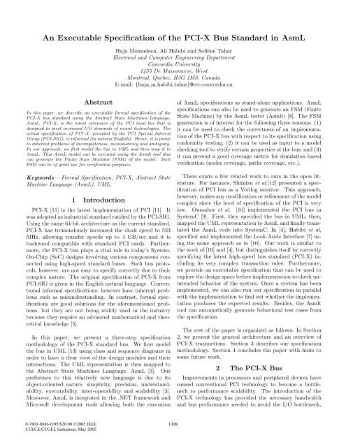
<strong>An</strong> <strong>Executable</strong> <strong>Specification</strong> <strong>of</strong> <strong>the</strong> <strong>PCI</strong>-X <strong>Bus</strong> <strong>Standard</strong> <strong>in</strong> <strong>AsmL</strong>Haja Mo<strong>in</strong>udeen, Ali Habibi and S<strong>of</strong>iène TaharElectrical and Computer Eng<strong>in</strong>eer<strong>in</strong>g DepartmentConcordia University1455 De Maisonneve, WestMontreal, Quèbec, H3G 1M8, CanadaE-mail: {haja m,habibi,tahar}@ece.concordia.caAbstractIn this paper, we describe an executable formal specification <strong>of</strong> <strong>the</strong><strong>PCI</strong>-X bus standard us<strong>in</strong>g <strong>the</strong> Abstract State Mach<strong>in</strong>es Language,<strong>AsmL</strong>. <strong>PCI</strong>-X, is <strong>the</strong> latest extension <strong>of</strong> <strong>the</strong> <strong>PCI</strong> local bus that isdesigned to meet <strong>in</strong>creased I/O demands <strong>of</strong> recent technologies. Theactual specification <strong>of</strong> <strong>PCI</strong>-X, provided by <strong>the</strong> <strong>PCI</strong> Special InterestGroup (<strong>PCI</strong>-SIG), is <strong>in</strong>formal (<strong>in</strong> natural English). Hence, it is proneto <strong>in</strong>herent problems <strong>of</strong> <strong>in</strong>completeness, <strong>in</strong>consistency and ambiguity.In our approach, we first model <strong>the</strong> bus <strong>in</strong> UML and <strong>the</strong>n map it to<strong>AsmL</strong>. This <strong>AsmL</strong> model can be executed us<strong>in</strong>g <strong>the</strong> Asmlt tool thatcan generate <strong>the</strong> F<strong>in</strong>ite State Mach<strong>in</strong>e (FSM) <strong>of</strong> <strong>the</strong> model. SuchFSM can be <strong>of</strong> great use for verification purposes.Keywords— Formal <strong>Specification</strong>, <strong>PCI</strong>-X, Abstract StateMach<strong>in</strong>e Language (<strong>AsmL</strong>), UML.1 Introduction<strong>PCI</strong>-X [11] is <strong>the</strong> latest implementation <strong>of</strong> <strong>PCI</strong> [11]. Itwas adopted as <strong>in</strong>dustrial standard ratified by <strong>the</strong> <strong>PCI</strong>-SIG.Us<strong>in</strong>g <strong>the</strong> same 64-bit architecture as <strong>the</strong> current standard,<strong>PCI</strong>-X has tremendously <strong>in</strong>creased <strong>the</strong> clock speed to 533MHz, allow<strong>in</strong>g transfer speeds up to 4 GB/sec and it isbackward compatible with standard <strong>PCI</strong> cards. Fur<strong>the</strong>rmore,<strong>the</strong> <strong>PCI</strong>-X bus plays a vital role <strong>in</strong> today’s System-On-Chip (SoC) designs <strong>in</strong>volv<strong>in</strong>g various components connectedus<strong>in</strong>g high-speed standard buses. Such bus protocols,however, are not easy to specify correctly due to <strong>the</strong>ircomplex nature. The orig<strong>in</strong>al specification <strong>of</strong> <strong>PCI</strong>-X from<strong>PCI</strong>-SIG is given <strong>in</strong> <strong>the</strong> English natural language. Conventional<strong>in</strong>formal specifications, however have <strong>in</strong>herent problemssuch as misunderstand<strong>in</strong>g. In contrast, formal specificationsare good solutions for <strong>the</strong> aforementioned problems,but <strong>the</strong>y are not be<strong>in</strong>g widely used <strong>in</strong> <strong>the</strong> <strong>in</strong>dustrybecause <strong>the</strong>y require an advanced ma<strong>the</strong>matical and <strong>the</strong>oreticalknowledge [5].In this paper, we present a three-step specificationmethodology <strong>of</strong> <strong>the</strong> <strong>PCI</strong>-X standard bus. We first model<strong>the</strong> bus <strong>in</strong> UML [13] us<strong>in</strong>g class and sequence diagrams <strong>in</strong>order to have a clear view <strong>of</strong> <strong>the</strong> design modules and <strong>the</strong>ir<strong>in</strong>teractions. The UML representation is <strong>the</strong>n mapped to<strong>the</strong> Abstract State Mach<strong>in</strong>es Language, <strong>AsmL</strong> [3]. Ourpreference to this relatively new language is due to itsobject-oriented nature, simplicity, precision, understandability,executability, <strong>in</strong>ter-operability and scalability [3].Moreover, <strong>AsmL</strong> is <strong>in</strong>tegrated <strong>in</strong> <strong>the</strong> .NET framework andMicros<strong>of</strong>t development tools allow<strong>in</strong>g both <strong>the</strong> execution<strong>of</strong> <strong>AsmL</strong> specifications as stand-alone applications. <strong>AsmL</strong>specifications can also be used to generate an FSM (F<strong>in</strong>iteState Mach<strong>in</strong>e) by <strong>the</strong> <strong>AsmL</strong> tester (Asmlt) [8]. The FSMgeneration is <strong>of</strong> <strong>in</strong>terest for <strong>the</strong> follow<strong>in</strong>g three reasons: (1)it can be used to check <strong>the</strong> correctness <strong>of</strong> an implementation<strong>of</strong> <strong>the</strong> <strong>PCI</strong>-X bus with respect to its specification us<strong>in</strong>gconformity test<strong>in</strong>g; (2) it can be used as <strong>in</strong>put to a modelcheck<strong>in</strong>g tool to verify certa<strong>in</strong> properties <strong>of</strong> <strong>the</strong> bus; and (3)it can present a good coverage metric for simulation basedverification (nodes coverage, paths coverage, etc.).There exists a few related work to ours <strong>in</strong> <strong>the</strong> open literature.For <strong>in</strong>stance, Shimizu et al.[12] presented a specification<strong>of</strong> <strong>PCI</strong> bus as a Verilog monitor. This approach,however, makes any modification or ref<strong>in</strong>ement <strong>of</strong> <strong>the</strong> modelcomplex s<strong>in</strong>ce <strong>the</strong> level <strong>of</strong> specification <strong>of</strong> <strong>the</strong> <strong>PCI</strong> is verylow. Oumalou et al. [10] implemented <strong>the</strong> <strong>PCI</strong> bus <strong>in</strong>SystemC [9]. First, <strong>the</strong>y specified <strong>the</strong> bus <strong>in</strong> UML; <strong>the</strong>n,mapped <strong>the</strong> UML representation to <strong>AsmL</strong> and f<strong>in</strong>ally translated<strong>the</strong> <strong>AsmL</strong> code <strong>in</strong>to SystemC. In [4], Habibi et al,specified and implemented <strong>the</strong> Look-Aside Interface [7] us<strong>in</strong>g<strong>the</strong> same approach as <strong>in</strong> [10]. Our work is similar to<strong>the</strong> work <strong>of</strong> [10] and [4], but dist<strong>in</strong>guishes itself by correctlyspecify<strong>in</strong>g <strong>the</strong> latest high-speed bus standard (<strong>PCI</strong>-X) <strong>in</strong>clud<strong>in</strong>gits very complex transaction rules. Fur<strong>the</strong>rmore,we provide an executable specification that can be used toexplore <strong>the</strong> design space before implementation to check un<strong>in</strong>tendedbehavior <strong>of</strong> <strong>the</strong> system. Once a system has beenimplemented, we can also run our specification <strong>in</strong> parallelwith <strong>the</strong> implementation to f<strong>in</strong>d out whe<strong>the</strong>r <strong>the</strong> implementationproduces <strong>the</strong> expected results. Besides, <strong>the</strong> Asmlttool can automatically generate behavioral test cases from<strong>the</strong> specification.The rest <strong>of</strong> <strong>the</strong> paper is organized as follows: In Section2, we present <strong>the</strong> general architecture and an overview <strong>of</strong><strong>PCI</strong>-X transactions. Section 3 describes our specificationmethodology. Section 4 concludes <strong>the</strong> paper with h<strong>in</strong>ts tosome future work.2 The <strong>PCI</strong>-X <strong>Bus</strong>Improvements <strong>in</strong> processors and peripheral devices havecaused conventional <strong>PCI</strong> technology to become a bottleneckto performance scalability. The <strong>in</strong>troduction <strong>of</strong> <strong>the</strong><strong>PCI</strong>-X technology has provided <strong>the</strong> necessary bandwidthand bus performance needed to avoid <strong>the</strong> I/O bottleneck,0-7803-8886-0/05/$20.00 ©2005 IEEECCECE/CCGEI, Saskatoon, May 20051308
thus achiev<strong>in</strong>g optimal system performance. For <strong>in</strong>stance,version 2.0 <strong>of</strong> <strong>PCI</strong>-X specifies a 64-bit connection runn<strong>in</strong>gat speeds <strong>of</strong> 66, 133, 266, or 533 MHz, result<strong>in</strong>g <strong>in</strong> a peakbandwidth <strong>of</strong> 533, 1066, 2133 or 4266 MB/s, respectively.<strong>PCI</strong>-X provides backward compatibility by allow<strong>in</strong>g devicesto operate at conventional <strong>PCI</strong> frequencies and modes.Moreover, <strong>PCI</strong>-X peripheral cards can operate <strong>in</strong> a conventional<strong>PCI</strong> slot, although only at <strong>PCI</strong> rates and may requirea 3.3 V conventional <strong>PCI</strong> slot. Similarly, a <strong>PCI</strong> peripheralcard with a 3.3 V or universal card edge connector can operate<strong>in</strong> a <strong>PCI</strong>-X slot, however <strong>the</strong> bus clock will rema<strong>in</strong> ata frequency acceptable to <strong>the</strong> <strong>PCI</strong> card. Figure 1 shows <strong>the</strong>general architecture <strong>of</strong> <strong>PCI</strong>-X with one Initiator (Master)and Target (Slave). There is an arbiter that performs <strong>the</strong>bus arbitration among multiple Initiators and Targets. Unlike<strong>the</strong> conventional <strong>PCI</strong> bus, <strong>the</strong> arbiter <strong>in</strong> <strong>PCI</strong>-X systemsmonitors <strong>the</strong> bus <strong>in</strong> order to ensure good function<strong>in</strong>g <strong>of</strong> <strong>the</strong>bus.GNT#REQ#INITIATORARBITERAD[31:0] / AD[63:0]C/BE [3:0] / C/BE[7:0]FRAME#IRDY#TRDY#DEVSEL#STOP#IDSELREQ#TARGETGNT#and IRDY# are used by <strong>the</strong> Arbiter to decide <strong>the</strong> grant<strong>in</strong>g<strong>of</strong> an Initiator request for <strong>the</strong> bus. Unlike <strong>PCI</strong>, <strong>the</strong> targetscan only <strong>in</strong>sert wait states by delay<strong>in</strong>g <strong>the</strong> assertion <strong>of</strong>TRDY#. TRDY# and IRDY# have to be asserted for avalid data transfer. <strong>An</strong> Initiator can abort <strong>the</strong> transactionei<strong>the</strong>r before or after <strong>the</strong> completion <strong>of</strong> <strong>the</strong> data transferby de-assert<strong>in</strong>g <strong>the</strong> FRAME# signal. In contrast, a Targetcan term<strong>in</strong>ate a bus transaction by assert<strong>in</strong>g STOP#. IfSTOP # is asserted without any data transfer, <strong>the</strong> Targethas issued a retry and if STOP# is asserted after one ormore data phases, <strong>the</strong> Target has issued a disconnect. Unlike<strong>PCI</strong>, <strong>the</strong> Target has also REQ# and GNT# that areconnected to <strong>the</strong> Arbiter. This facilitates <strong>the</strong> Split Transaction<strong>of</strong> <strong>PCI</strong>-X which does not exist <strong>in</strong> conventional <strong>PCI</strong>.3 <strong>Specification</strong> MethodologyFigure 2 depicts our specification methodology <strong>of</strong> <strong>the</strong><strong>PCI</strong>-X bus standard. We start with <strong>the</strong> <strong>in</strong>formal specificationgiven <strong>in</strong> [11], where all protocol rules have been described.The core components <strong>of</strong> <strong>the</strong> protocol, <strong>the</strong> differenttypes <strong>of</strong> transactions and respective transaction rules areidentified. Thereafter, we specify <strong>the</strong> bus semi-formally us<strong>in</strong>gUML’s class and sequence diagrams. From <strong>the</strong> sequencediagrams, we write <strong>the</strong> formal (executable) specification <strong>of</strong><strong>the</strong> bus us<strong>in</strong>g <strong>AsmL</strong> and <strong>the</strong>n compile it us<strong>in</strong>g <strong>the</strong> <strong>AsmL</strong>tool (Asmlt). The Asmlt has its own FSM generation algorithmfrom <strong>the</strong> <strong>AsmL</strong> code and can generate test cases<strong>in</strong> C# [1]. Such C# test cases can be used to verify <strong>the</strong>model by simulation.Informal <strong>Specification</strong>CLOCKUML Representation(Class Diagram, Sequence Diagram)Figure 1:General Architecture <strong>of</strong> <strong>PCI</strong>-X.<strong>PCI</strong>-X supports two modes <strong>of</strong> transactions: Mode 1 andMode 2. Mode 1 operates at ei<strong>the</strong>r 66 or 133 MHz and usesa parity error check<strong>in</strong>g scheme. The higher transfer rates(266 or 533 MHz) <strong>in</strong> <strong>PCI</strong>-X 2.0 are def<strong>in</strong>ed <strong>in</strong> Mode 2, whichuses ECC as its error correct<strong>in</strong>g scheme. Split Transactions<strong>in</strong> <strong>PCI</strong>-X replace Delayed Transactions <strong>in</strong> conventional <strong>PCI</strong>[11]. If a Target cannot complete <strong>the</strong> transaction with<strong>in</strong> <strong>the</strong>Target <strong>in</strong>itial latency limit, <strong>the</strong> Target must complete thattransaction as Split Transaction. If <strong>the</strong> Target meets its<strong>in</strong>itial latency limits, it can optionally complete <strong>the</strong> transactionimmediately.Both <strong>PCI</strong>-X Initiator and Target has a pair <strong>of</strong> arbitrationl<strong>in</strong>es that are connected to <strong>the</strong> Arbiter. When an Initiatorrequires <strong>the</strong> bus, it asserts REQ#. If <strong>the</strong> arbiter decides togrant <strong>the</strong> bus to that Initiator, it asserts GNT#. FRAME#Figure 2:FSM<strong>AsmL</strong> Model<strong>AsmL</strong> ToolTest Cases<strong>PCI</strong>-X <strong>Specification</strong> Methodology.3.1 UML RepresentationThe core components <strong>of</strong> <strong>the</strong> bus viz, Initiators, Targets,Arbiters, <strong>PCI</strong>-X bus are represented as classes, where specific<strong>in</strong>stances <strong>of</strong> <strong>the</strong> components are called as objects. In1309
addition to <strong>the</strong>se four components, we also added ano<strong>the</strong>rcomponent, <strong>the</strong> Simulation Manager (SimManager), <strong>in</strong> orderto have a notion <strong>of</strong> <strong>the</strong> Clock. The detailed description<strong>of</strong> <strong>the</strong>se components (classes) is discussed <strong>in</strong> Section 3.2.Figure 3 shows <strong>the</strong> class diagram <strong>of</strong> <strong>the</strong> <strong>PCI</strong>-X bus. As itcan be seen from <strong>the</strong> figure, we have five classes and eachclass has its own data members and methods.InitiatorReq#_assert@clkNFRAME#_assert@clkN+2(Address Phase)<strong>PCI</strong>-X-<strong>Bus</strong>GNT#_assert@clkN+1AttributePhase@clkN+3ArbiterTargetDEVSEL#_assert@clkN+4<strong>PCI</strong>X_Initiator+REQ : BaseVar+GNT : BaseVar+FRAME : BaseVar+IRDY : BaseVar+IDSEL : BaseVar+AD : BaseVar+CBE : BaseVar+DEST : BaseVar+STOP : BaseVar+<strong>PCI</strong>X_Initiator()+<strong>PCI</strong>X_Initiator_Req()+<strong>PCI</strong>X_Initiator_FRAME_Assert()+<strong>PCI</strong>X_Attribute_Phase()+<strong>PCI</strong>X_Initiator_IRDY_Assert()+<strong>PCI</strong>X_Initiator_Term<strong>in</strong>ation()+<strong>PCI</strong>X_Initiator_Abort()+<strong>PCI</strong>X_Initiator_LastPhase()+<strong>PCI</strong>X_Initiator_Release()**1<strong>PCI</strong>X_Arbiter+Active_Initiator : BaseVar+REQ : BaseVar+GNT : BaseVar+CBE : BaseVar+FRAME : BaseVar+IRDY : BaseVar+<strong>PCI</strong>X_Arbiter()+<strong>PCI</strong>X_Arbiter_GNT()+<strong>PCI</strong>X_Arbiter_Park_Initiator()**1**<strong>PCI</strong>X_Target+REQ : BaseVar+GNT : BaseVar+TRDY : BaseVar+DEVSEL : BaseVar+STOP : BaseVar+AD : BaseVar+CBE : BaseVar+ID : BaseVar+TARGET_STOP : BaseVar+<strong>PCI</strong>X_Target()+<strong>PCI</strong>X_Target_DEVSEL_Assert()+<strong>PCI</strong>X_Target_TRDY_Assert()+<strong>PCI</strong>X_Target_Abort()+<strong>PCI</strong>X_Target_Term<strong>in</strong>ation()*IRDY#_assert@clkN+5FRAME#_negate@clkN+7(Initiator Term<strong>in</strong>ation)IRDY#_negate@clkN+9Data Phase#1Data Phase#2Data Phase#M-1Data Phase#MTerm<strong>in</strong>ation PhaseTRDY#_assert@clkN+5DEVSEL#, STOP#,TRDY#Negate@clkN+9*1SimManager+CLK : BaseVar+SimManager()+<strong>PCI</strong>X_SimManager_Init()+<strong>PCI</strong>X_SimManager_CLK_Update()11Figure 3:1111<strong>PCI</strong>X_<strong>Bus</strong>+CLK : BaseVar+FRAME : BaseVar+IRDY : BaseVar+TRDY : BaseVar+DEVSEL : BaseVar+STOP : BaseVar+AD : BaseVar+CBE : BaseVar+<strong>PCI</strong>X_<strong>Bus</strong>()+<strong>PCI</strong>X_BUS_DataPhase()-<strong>PCI</strong>X_<strong>Bus</strong>_common()Class Diagram <strong>of</strong> <strong>PCI</strong>-X.In Figure 4, we show <strong>the</strong> protocol sequence <strong>of</strong> <strong>the</strong> Mode 1transaction <strong>of</strong> <strong>PCI</strong>-X us<strong>in</strong>g a sequence diagram. Figure 4 isa best case scenario <strong>of</strong> Mode 1 transactions, with one Initiatorand one Target and without any wait states. In <strong>the</strong> firstclock cycle, <strong>the</strong> Initiator asserts <strong>the</strong> REQ# signal to get <strong>the</strong>control <strong>of</strong> <strong>the</strong> bus. The Arbiter asserts <strong>the</strong> GNT# signal tothat Initiator. In <strong>the</strong> third clock cycle, <strong>the</strong> address phasetakes place and also <strong>the</strong> FRAME# signal is asserted by <strong>the</strong>Initiator to signal <strong>the</strong> start <strong>of</strong> <strong>the</strong> transaction. In <strong>the</strong> nextclock cycle, <strong>the</strong> attribute phase takes place, where additional<strong>in</strong>formation <strong>in</strong>cluded with each transaction is added.In clock cycle N+4, <strong>the</strong> DEVSEL# signal is asserted by<strong>the</strong> Target and <strong>in</strong> <strong>the</strong> next clock cycle, <strong>the</strong> data phase isstarted with <strong>the</strong> assertion <strong>of</strong> <strong>the</strong> IRDY# and TRDY# signalsby <strong>the</strong> Initiator and <strong>the</strong> Target, respectively. Before<strong>the</strong> last data phase, <strong>the</strong> FRAME# signal is de-asserted tosignal <strong>the</strong> completion <strong>of</strong> <strong>the</strong> data transfer and <strong>in</strong> <strong>the</strong> term<strong>in</strong>ationphase all <strong>the</strong> o<strong>the</strong>r signals are de-asserted. In orderto represent <strong>the</strong> clock constra<strong>in</strong>ts <strong>of</strong> <strong>the</strong> <strong>PCI</strong>-X transaction,we added an additional operator @. This operator is usedto specify at which clock cycle a particular action shouldoccur.3.2 <strong>AsmL</strong> ModelIn this section, we discuss our approach <strong>of</strong> mapp<strong>in</strong>g <strong>the</strong>UML representation <strong>of</strong> <strong>PCI</strong>-X <strong>in</strong>to an <strong>AsmL</strong> model byshow<strong>in</strong>g some <strong>of</strong> <strong>the</strong> important methods <strong>of</strong> our <strong>AsmL</strong> code.We used <strong>AsmL</strong>’s class features to model all four componentsdiscussed <strong>in</strong> <strong>the</strong> previous section. Each <strong>of</strong> <strong>the</strong>se hasits own data members (signals) and methods (behavior) <strong>in</strong>1Figure 4:Sequence Diagram <strong>of</strong> Mode 1 Transaction.addition to <strong>the</strong> Constructors. Constructors are used to <strong>in</strong>itialize<strong>the</strong> objects and <strong>the</strong>y are <strong>in</strong>voked whenever an objectis created. We also used enumeration features (enum) <strong>of</strong><strong>AsmL</strong> to model different modes <strong>of</strong> <strong>PCI</strong>-X, different types <strong>of</strong>transaction phases, <strong>the</strong> state <strong>of</strong> <strong>the</strong> system and <strong>the</strong> clock.(see Figure 5).enum SystemStatusINITSTARTEDenum Transaction_PhaseIDLE_PHASEADDR_PHASEATTR_PHASETGT_RES_PHASEDATA_PHASEINR_TER_PHASETURN_AROUND_PHASEFigure 5:enum ClockCLK_UPCLK_DOWNenum Transaction_ModeMODE_1MODE_2Enumeration <strong>in</strong> <strong>the</strong> <strong>AsmL</strong> Model.In addition, we exhaustively used <strong>the</strong> require and ”:=”statements <strong>of</strong> <strong>AsmL</strong> <strong>in</strong> our design approach. require is <strong>the</strong>pre-condition statement <strong>in</strong> <strong>AsmL</strong> used to check if a certa<strong>in</strong>condition is satisfied or not, and ”:=” is <strong>the</strong> update statementused to change <strong>the</strong> system state. Figure 6 shows <strong>the</strong>Arbiter grant method (<strong>PCI</strong>X Arbiter GNT()). In order togrant <strong>the</strong> bus to <strong>the</strong> requested Initiator, this method has<strong>the</strong> follow<strong>in</strong>g pre-conditions (require) to be met: (1) <strong>the</strong>remust be at least one Initiator request<strong>in</strong>g <strong>the</strong> bus and thatInitiator has not been granted <strong>the</strong> bus at <strong>the</strong> time <strong>of</strong> <strong>the</strong> request;(2) <strong>the</strong> clock is on <strong>the</strong> ris<strong>in</strong>g edge; and (3) <strong>the</strong> modecan be ei<strong>the</strong>r Mode 1 or Mode 2. If <strong>the</strong>se pre-conditionsare met, <strong>the</strong> Arbiter updates <strong>the</strong> GNT# signal.Figure 7 shows <strong>the</strong> Initiator term<strong>in</strong>ation method(<strong>PCI</strong>X Initiator Term<strong>in</strong>ation). This method basically signals<strong>the</strong> end <strong>of</strong> a transaction if BYTECOUNT is less than2. This signal<strong>in</strong>g is done by de-assert<strong>in</strong>g <strong>the</strong> FRAME#1310
public <strong>PCI</strong>X_Arbiter_GNT()require(exists x <strong>in</strong> Initiators where x.REQ = true and x.GNT = false) and me.GNT =false and Smanager.CLK = CLK_UP and (Mode = MODE_1 or Mode = MODE_2)me.Active_Initiator := m<strong>in</strong> y | y <strong>in</strong> Initiators_Range where (Initiators(y).REQ =true)me.REQ := truerequire me.REQ = true and me.GNT = falseme.GNT := trueInitiators(Active_Initiator).GNT := trueFigure 6:Arbiter GNT Method.signal and updat<strong>in</strong>g <strong>the</strong> transaction phase to InitiatorTerm<strong>in</strong>ation Phase (INI TER PHASE). This method hassome pre-conditions that need to be true so that it canterm<strong>in</strong>ate <strong>the</strong> transactions. The pre-conditions (require)are <strong>the</strong> follow<strong>in</strong>g: Initiator’s REQ#, GNT#, FRAME#,IRDY#, DEVSEL#, TRDY# are asserted, BYTECOUNTis less than 2, and <strong>the</strong> clock is on <strong>the</strong> ris<strong>in</strong>g edge. Ifall <strong>the</strong> above pre-conditions are true, this method updates<strong>the</strong> FRAME# signal to false and <strong>the</strong> phase toINI TER PHASE us<strong>in</strong>g <strong>the</strong> ”:=” operator. After thisFRAME# signal de-assertion, <strong>the</strong> Initiator’s last phasemethod (<strong>PCI</strong>X Initiator LastPhase()) is <strong>in</strong>voked.public <strong>PCI</strong>X_Initiator_Term<strong>in</strong>ation()require me.GNT = true and me.REQ = true and me.FRAME = true andme.IRDY = true and <strong>Bus</strong>.TRDY = true and <strong>Bus</strong>.DEVSEL = true andBYTECOUNT < 2 and me.STOP = false and Smanager.CLK = CLK_UPme.FRAME := false<strong>Bus</strong>.FRAME := falsePhase := INR_TER_PHASEFigure 7:Initiator Term<strong>in</strong>ation Method.Figure 8 shows <strong>the</strong> clock update method <strong>of</strong> <strong>the</strong> <strong>AsmL</strong>code. It checks if <strong>the</strong> system and simulation are started <strong>in</strong>order to update <strong>the</strong> clock.public <strong>PCI</strong>X_SimManager_CLK_Update()require SystemFlag = STARTED and SimStatus = RUNNINGif CLK = CLK_UP <strong>the</strong>nCLK := CLK_DOWNelseCLK := CLK_UPFigure 8:Clock Update Method.Figure 9 shows <strong>the</strong> data phase method <strong>of</strong> <strong>the</strong> <strong>AsmL</strong> code.The method decreases <strong>the</strong> BYTECOUNT by 1 based on <strong>the</strong>follow<strong>in</strong>g pre-conditions: IRDY#, DEVSEL#, TRDY#are asserted, <strong>the</strong> phase has <strong>the</strong> value DATA PHASE, <strong>the</strong>clock is on <strong>the</strong> ris<strong>in</strong>g edge, and <strong>the</strong> system started runn<strong>in</strong>g.public <strong>PCI</strong>X_BUS_DataPhase()require SystemFlag = STARTED and SimStatus = ON_INIT and<strong>Bus</strong>.IRDY = true and <strong>Bus</strong>.TRDY = true and <strong>Bus</strong>.DEVSEL = trueand Smanager.CLK = CLK_UP and Phase = DATA_PHASEBYTECOUNT := BYTECOUNT - 1Figure 9:Data Phase Method.Once <strong>the</strong> model<strong>in</strong>g <strong>of</strong> <strong>the</strong> bus <strong>in</strong> <strong>AsmL</strong> was completed,we used <strong>the</strong> Asmlt tool to execute <strong>the</strong> <strong>AsmL</strong> code and generated<strong>the</strong> model’s FSM. Details <strong>of</strong> our <strong>AsmL</strong> implementation,UML representations and <strong>the</strong> generated FSM <strong>of</strong> <strong>the</strong><strong>PCI</strong>-X standard bus can be found <strong>in</strong> <strong>the</strong> project website 1 .4 ConclusionsIn this paper, we presented an executable specification <strong>of</strong><strong>PCI</strong>-X bus standard us<strong>in</strong>g UML representation and <strong>AsmL</strong>.Start<strong>in</strong>g from <strong>the</strong> <strong>in</strong>formal description <strong>of</strong> <strong>the</strong> bus standard,we provided a formal specification us<strong>in</strong>g <strong>the</strong> UML class andsequence diagrams <strong>the</strong>n mapped <strong>the</strong> sequence diagrams <strong>in</strong>toan <strong>AsmL</strong> model. The <strong>AsmL</strong> model is executed us<strong>in</strong>g Micros<strong>of</strong>t’sAsmlt tool and an FSM <strong>of</strong> <strong>the</strong> model is generated.In a future work, <strong>the</strong> generated FSM can be used as <strong>in</strong>putto verify formally us<strong>in</strong>g model check<strong>in</strong>g tools such as SMV[6] or FormalCheck [2]. The developed model can also beused to check <strong>the</strong> correctness <strong>of</strong> an implementation <strong>of</strong> <strong>the</strong><strong>PCI</strong>-X bus with respect to its specifications us<strong>in</strong>g conformitytest<strong>in</strong>g <strong>in</strong> Asmlt.References[1] C# Language <strong>Specification</strong>, Micros<strong>of</strong>t Incorporation.http://msdn.micros<strong>of</strong>t.com/vcsharp, 2004.[2] Cadence. Affirma Formalcheck version 2.6, 2000.[3] Y. Gurevich, B. Rossman, and W. Schulte. SemanticEssence <strong>of</strong> <strong>AsmL</strong>. Technical report, Micros<strong>of</strong>t Research,MSR-TR-2004-27, March 2004.[4] A. Habibi, A.I. Ahmed, O. Ait-Mohamed, and S.Tahar. On <strong>the</strong> design and verification <strong>of</strong> <strong>the</strong> lookaside<strong>in</strong>terface. In Proc. Design Automation and Test<strong>in</strong> Europe, Munich, Germany, March 2005 (to appear).[5] A. V. Lamsweerde. Formal <strong>Specification</strong>: A Roadmap.In Proc. <strong>of</strong> Conference on The Future <strong>of</strong> S<strong>of</strong>twareEng<strong>in</strong>eer<strong>in</strong>g, pages 147–159, Limerick, Ireland, June,2000. ACM Press.[6] K. L. McMillan. Symbolic Model Check<strong>in</strong>g. KluwerAcademic Publishers, 1993.[7] Network Process<strong>in</strong>g Forum. Look-Aside (LA-1) Interface,Implementation Agreement, Revision 1.1. KluwerAcademic Publishers, April 15, 2004.[8] Micros<strong>of</strong>t Research Foundations <strong>of</strong> S<strong>of</strong>twareEng<strong>in</strong>eer<strong>in</strong>g. Asml for micros<strong>of</strong>t .net.http://www.research.micros<strong>of</strong>t.com/foundations/asml.[9] Open SystemC Initiative. www.systemc.org, 2004.[10] K. Oumalou, A. Habibi, and S. Tahar. Design for verification<strong>of</strong> a <strong>PCI</strong> bus <strong>in</strong> SystemC. In Proc. Symposiumon System-on-Chip, pages 201–204, Tampere, F<strong>in</strong>land,November 2004.[11] <strong>PCI</strong> Special Interest Group. www.pcisig.com, 2004.[12] K. Shimizu, D. L. Dill, and A. J. Hu. Monitor-basedformal specification <strong>of</strong> <strong>PCI</strong>. In Formal Methods <strong>in</strong>Computer-Aided Design, pages 335–353. LNCS 1954,Spr<strong>in</strong>ger-Verlag, 2000.[13] Unified Model<strong>in</strong>g Language. http://www.uml.org,2003.1 http://hvg.ece.concordia.ca/Research/Soc/<strong>PCI</strong>X1311