Full resolution - ThePlaz.com
Full resolution - ThePlaz.com
Full resolution - ThePlaz.com

You also want an ePaper? Increase the reach of your titles
YUMPU automatically turns print PDFs into web optimized ePapers that Google loves.
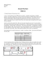
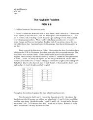
PRS: LC Circuit<br />
Consider the LC circuit at<br />
right. At the time shown the<br />
current has its ~<br />
value. At this time<br />
-<br />
D<br />
L<br />
c- l<br />
0% ~ The charge 00 the capacitor has its maximum value""" 11\ It). }LJt<br />
'" ~ The magnetic field is zero<br />
0% The eleclrlc field has its maximum value .-!!JIt{1<br />
. . J<br />
-<br />
f<br />
0% 4. The charge on the capaCitor IS zero<br />
0% . Don't have a clue<br />
~I~" (e~r''w)<br />
td<br />
'3 rv \'Vt'lo ~U '( <<br />
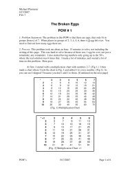
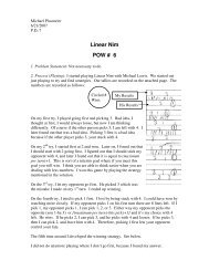
PRS: LC Circuit<br />
In the LC circuit at right the e<br />
current is in the direction<br />
==<br />
shown and the charges on<br />
the capacitor have the signs F<br />
shown. At this time,<br />
-Q +Q<br />
:r<br />
0% @ I is increasing and Q is increasing<br />
0% I is increasing and Q is decreasing<br />
0% 3. I is decreasing and Q is increasing<br />
'"<br />
'"<br />
4. I is decreasing and Q is decreasing<br />
5. Don't have a clue<br />
11'<br />
J\'C~'el/<br />
()J<br />
,,~<br />
PRS Answer: LC Circuit<br />
D<br />
Answer: 4. The current is<br />
maximum when the charge<br />
on the capacitor is zero<br />
Current and charge are exactly 90 degrees out of<br />
phase in an ideal LC circuit (no resistance). so when<br />
the current is maximum the charge must be<br />
identically zero.<br />
t1,now<br />
(htij f; € tl<br />
f ~C'.)\ vd lJ~<br />
PRS Answer: LC Circuit<br />
Answer: 2. I is increasing;<br />
Q is decreasing<br />
With current in the direction<br />
shown, the capacitor is<br />
discharging (Q is decreasing).<br />
But since Q on the right plate is positive, I must be<br />
increasing. The positive charge wants to flow, and<br />
the current will increase until the charge on the<br />
capacitor changes sign. That is, we are in the first<br />
quarter period of the discharge of the capacitor,<br />
when Q is decreasing and positive and I is<br />
increasing and positive.<br />
t"·»<br />
.)'1'<br />
~-f ,.<br />
4."t\\ '(I!J<br />
(}\f\'1 ",,.>/<br />
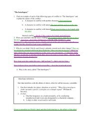
PRS: LC Circuit<br />
The plot shows the charge ' ..... =-.---,="<br />
on a c~ r (black curve) ~ .<br />
and the current through it<br />
(red curve) after you turn<br />
off the power supply. If yOU ! 4J<br />
J~ I<br />
r .... lfOS)<br />
" 0<br />
C~v'(tE<br />
Core. l' L<br />
~O wht-ti<br />
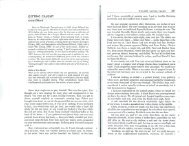
PRS Answer: LC Circuit<br />
Answer:<br />
1. T Lag will increase 11 ..... '<br />
, I ·<br />
s~~· t++++-I~+-I+J'<br />
!-<br />
. ,,,,.~<br />
---.:.--::.:--;i,;,'0>'<br />
,-....<br />
Putting in a core increases the inductor's<br />
inductance and hence decreases the natural<br />
frequency of the circuit. Lower frequency means<br />
longer period. The phase will remain at 90' (a<br />
quarter period) so T lag will increase.<br />
---.oc.<br />
\vtl l Tl-~<br />
1,[ l; vU{<br />
}W4>" 7' L<br />
h,,~~erSr Mv' Jcz ) { el\o(l,V\ lp/ th 'q<br />
J